1
09/09 Rev. 5.03-01
USER- / SERVICE MANUAL
AP 4.4 – AP 5.4 – AP 7.t
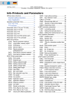
Info Printouts & Parameters
General Information ...................................... 5
Important setting instructions .................... 5
Area of application .................................... 5
Operating the parameter menu ..................... 7
Example .................................................... 7
Parameter Menu ...................................... 8
Overview Parameter Menus ......................... 9
Understanding the Parameter Overviews . 9
AP 5.4 Parameter .................................... 10
AP 4.4 Parameter .................................... 13
AP 7.t Parameter ..................................... 15
Alphabetical Parameter List ........................ 18
PRINT INFO
Printer status ........................................... 21
Memory status ......................................... 23
Font status .............................................. 24
Flashdata status...................................... 27
Textile care sym. ..................................... 28
Service Status ......................................... 29
Dottest endless ....................................... 30
Dottest punched ...................................... 30
Reference label ....................................... 31
PRINT PARAMETERS
Print speed .............................................. 32
Feed speed ............................................ 32
Material type............................................ 32
Material length......................................... 33
Material width .......................................... 33
Print direction .......................................... 34
Punch offset ............................................ 35
Bar code multip. ...................................... 35
Tradit. Imaging ....................................... 36
UPC plain-copy ....................................... 36
EAN Readline.......................................... 36
EAN sep. lines......................................... 37
Rotated Barcodes ................................... 37
Cut mode................................................. 38
Cut speed................................................ 40
Cut position ............................................. 40
Double cut ............................................... 40
Rewind direction ......................................41
X - Printadjust .......................................... 41
Y – Printadjust ......................................... 41
Punch mode............................................. 42
Punch level .............................................. 42
INTERFACE PARA
> EASYPLUGINTERPR
Interface...................................................
Spooler mode ..........................................
Printer ID No. ...........................................
Spooler size .............................................
Offline mode ............................................
Interface delay .........................................
43
43
44
44
44
44
> COM1 PORT
Baud rate .................................................
No. of data bits.........................................
Parity........................................................
Stop bits...................................................
Data synch...............................................
Frame error..............................................
45
45
45
45
46
46
> COM2 PORT
Baud rate .................................................
No. of data bits.........................................
Parity........................................................
Stop bits...................................................
Data synch...............................................
Serial Port Mode ......................................
Frame error..............................................
46
46
46
47
47
47
47
> COM3 PORT
Baud rate .................................................
No. of data bits.........................................
Parity........................................................
Stop bits...................................................
Data synch...............................................
Frame error..............................................
48
48
48
48
48
48
> CENTRONICS
PnP function ............................................ 49
> NETWORK PARAM.
IP addressassign ..................................... 49
09/09 Rev. 5.03-01
USER- / SERVICE MANUAL
AP 4.4 – AP 5.4 – AP 7.t
IP address ............................................... 49
Net mask ................................................. 49
Gateway address .................................... 50
Port address............................................ 50
Ethernet speed........................................ 50
MAC address .......................................... 50
SNMP agent............................................ 50
SNMP password ..................................... 50
FTP server .............................................. 51
FTP password ......................................... 51
WEB server ............................................. 52
WEB display refr ..................................... 53
WEB admin passw. ................................. 53
WEB supervisor p. .................................. 53
Time client............................................... 54
Time server IP......................................... 54
Sync. Interval .......................................... 54
DHCP host name .................................... 55
WLAN SSID ............................................ 55
WLAN WEP............................................. 55
WLAN default key ................................... 56
WLAN 64Bit key 1 ................................... 56
WLAN 64Bit key 2 ................................... 56
WLAN 64Bit key 3 ................................... 56
WLAN 64Bit key 4 ................................... 56
WLAN 128Bit key 1 ................................. 57
WLAN 128Bit key 2 ................................. 57
WLAN 128Bit key 3 ................................. 57
WLAN 128Bit key 4 ................................. 57
WLAN com quality................................... 57
WLAN signal lev...................................... 58
> OPTIONS
Remote Display....................................... 58
RFID Option ............................................ 59
StandAlone Input..................................... 59
SYSTEM PARAMETERS
Foil end warning......................................
Foil warn stop..........................................
Print Interpret. .........................................
Character sets.........................................
Character filter.........................................
60
60
61
62
63
Light sens. type........................................
Head-sensor dist......................................
Sens. punch-LS .......................................
Ribbon autoecon......................................
Feed mode...............................................
Foil mode .................................................
Turn-on mode ..........................................
Error reprint..............................................
EasyPlug error .........................................
Single job mode .......................................
Head resistance.......................................
Temp. reduction.......................................
Thin line emphas .....................................
Voltage offset...........................................
Miss. label tol. ..........................................
Gap detect mode .....................................
Periph. device ..........................................
Singlestartquant.......................................
External signal .........................................
Start mode ...............................................
Signal edge..............................................
Print contrast............................................
Ram disk size ..........................................
Font downl. area ......................................
Free store size .........................................
Print info mode.........................................
Reprint function........................................
Language.................................................
Keyboard .................................................
Access authoriz. ......................................
Realtime clock .........................................
63
63
64
64
65
65
65
65
65
66
66
67
67
67
68
68
69
69
69
70
71
71
72
72
73
73
73
74
74
74
76
I/O BOARD
Start delay................................................
Start print mode .......................................
Reprint Signal ..........................................
Feed input................................................
Pause input..............................................
Error output..............................................
Error Polarity............................................
Status output ...........................................
Status polarity ..........................................
End print mode ........................................
77
77
78
78
78
79
79
80
80
80
09/09 Rev. 5.03-01
USER- / SERVICE MANUAL
AP 4.4 – AP 5.4 – AP 7.t
DISPENSER PARA
Dispense Mode ....................................... 81
Dispenseposition..................................... 82
Display mode .......................................... 83
Dispense counter .................................... 83
Application mode..................................... 83
Start mode............................................... 84
Start source............................................. 84
Calibration mode ..................................... 84
Current mode .......................................... 85
Min. rew. current ..................................... 85
Max. rew. current .................................... 86
Start rew. current..................................... 86
Start cur. len. ........................................... 87
Pullback current ...................................... 87
Back diameter ......................................... 87
Brake current........................................... 88
Brake diameter........................................ 88
REWINDER PARA
Rewind direction...................................... 89
Start mode............................................... 89
Current mode .......................................... 89
Min. rew. current ..................................... 89
Max rew. current ..................................... 89
Start rew. curr.......................................... 90
Start cur. len............................................ 90
Pullback current ...................................... 90
Back diameter ......................................... 90
Brake current........................................... 90
Break diameter ........................................ 91
MLI PARAMETERS
Version ....................................................
Darkness .................................................
Control Prefix ..........................................
Format Prefix...........................................
Delimiter Char .........................................
Label Top ................................................
Left Position ............................................
Manual Calibrate .....................................
Resolution ...............................................
Error Indication........................................
92
92
92
93
93
93
93
93
94
94
Error Checking.........................................
Image Save Path .....................................
Command ^PR .......................................
Command ^MT .......................................
Label Invert ..............................................
Command ^JM........................................
94
94
94
95
95
95
TEXTILE PARAMETE
Changelabel mode................................... 96
Changelab Print ....................................... 96
Changelab Length ................................... 96
Label eject mode .....................................97
Head lift autom......................................... 97
Head clean............................................... 97
SPECIAL FUNCTION
Printer type .............................................. 98
Default Values ......................................... 98
Command sequence................................ 98
Delete job................................................. 98
Delete spooler.......................................... 99
Factory settings ....................................... 99
Parameter to CF ...................................... 99
Diagnosis to CF ..................................... 100
Data blocks del. ..................................... 100
EasyPl. file log ....................................... 101
Log files delete....................................... 101
RFID stat. del......................................... 101
SERVICE FUNCTION
Service................................................... 102
Head exchange...................................... 102
Roller exchange..................................... 102
Cutter exchange ....................................103
Serv. data reset ..................................... 103
EasyPlug monitor................................... 103
EP Monitor Mode ...................................104
Head adjust............................................ 104
Sensor adjust......................................... 104
Sensor test ............................................ 104
Cutter test .............................................. 104
Matend adjust ........................................105
Matend tolerance ................................... 105
09/09 Rev. 5.03-01
USER- / SERVICE MANUAL
AP 4.4 – AP 5.4 – AP 7.t
Feedadjust label.................................... 105
Feed adjust ........................................... 106
Punch y calibr........................................ 106
CompactFlashTest ................................ 106
Send test ............................................... 107
Receive test .......................................... 108
Rewinder adjust .................................... 109
Com2 commun. test .............................. 110
Com2 port test....................................... 110
Printtest ................................................. 110
SERVICE DATA
> MODULE FW VERS.
System version......................................
System revision.....................................
System date ..........................................
Bootloader.............................................
uMon .....................................................
Feed driver ............................................
Head driver............................................
Peripheraldriver.....................................
Intern. rewinder .....................................
111
111
111
111
111
111
111
112
112
> OPERATION DATA
Serv. operations ....................................
Headnumber .........................................
Roll number...........................................
Cutter number .......................................
Head run length.....................................
Roll run length .......................................
Cuts on knife .........................................
Tot. mat. length .....................................
Tot. foil length........................................
112
112
112
112
113
113
113
113
113
Total cuts ...............................................
Total head moves ..................................
Head strobes .........................................
Head temperature..................................
Foil diameter ..........................................
Dispensing cycl......................................
Operation time .......................................
113
114
114
114
114
114
114
> POWERSUPPLYDATA
Type....................................................... 115
PS temperature...................................... 115
> CPU BOARD DATA
CPU identifier.........................................
PCB revision ..........................................
FPGA version ........................................
MAC address .........................................
Serial number ........................................
Production date......................................
PCB part number ...................................
Board part numb. ...................................
Manufacturer..........................................
Work place.............................................
Company name .....................................
115
115
115
115
115
116
116
116
116
116
116
> CF CARD SLOT
Card in slot............................................. 117
Card type ............................................... 117
> MEMORY DATA
Ram memory size..................................
Flash mem size......................................
CompactFlash........................................
Space for Jobs.......................................
Max. Labellength ...................................
Default values ........................................
117
117
118
118
118
118
5
09/09 Rev. 5.03-01
USER- / SERVICE MANUAL
Info-Printouts & Parameters
AP 4.4 – AP 5.4 – AP 7.t
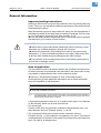
General Information
Important setting instructions
Starting in offline mode, you get to the parameter menu by pressing the prog
button. There you can set/alter the different parameters of the printer and activate/deactivate options.
Many Parameters provide a range within the setting can be changed with a
standard step width. By this step width, the setting is changed, if the Cut-(Apply-) or Feed button is pressed once (Min. firmware: 5.31).
¯ The step width can be increased ten times, if the Online button is pressed
simultaneously (Cut+Online or Feed+Online).
CAUTION!
¯ Wait at least 10 seconds between switching the device off and on again,
otherwise any modified parameter settings are not saved.
¯ With some parameters, false settings can result in the device being
damaged (e. g. if the print head temperature is too high). Data and/or print
orders are also deleted during formatting and with other settings.
¯ Pay attention to the corresponding notes in the following description to
ensure that no damage occurs!
Area of application
The description counts for all devices listed in the headline of this document.
All status printouts and parameters are described in the same order as they
may appear in the parameter menu of the respective printer.
¯ Not all of
the parameters appear in each of the listed printers!
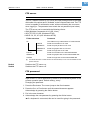
At the beginning of each parameter description can be found information
about the availability of the parameter:
AP 5.4
¯ Only with installed I/O board.
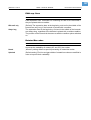
Fig. 1:
At the beginning of each parameter description, the availability of the parameter is
specified: Between the two lines is a list of the concerned printer types; the remark
below (arrow) quotes further conditions.
If a parameter appears in the menu of a certain printer type or not, depends
on the following, which can be read from this bar:
y The printer type:
Printers, which have the parameter available in the parameter menu, are
listed between the lines. Example (see fig. 1): AP 5.4.
y The configuration with options and/or certain parameter settings:
Example (see fig. 1): The parameter only appears in the menu, if the device
is equipped with an I/O board. If the remark is not assigned to a special printer
type, it is valid for all listed printers.
6
09/09 Rev. 5.03-01
USER- / SERVICE MANUAL
Info-Printouts & Parameters
AP 4.4 – AP 5.4 – AP 7.t
Firmware
This description applies to all printers which are equipped with a firmware
version 3.33 for AP5.4, AP 7.t, AP 4.4 (16 MB RAM).
P The paragraph Overview Parameter Menues in this topic section contains an
overview of all available parameters of the respective printer.
7
09/09 Rev. 5.03-01
USER- / SERVICE MANUAL
Info-Printouts & Parameters
AP 4.4 – AP 5.4 – AP 7.t
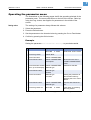
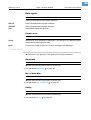
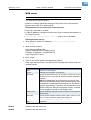
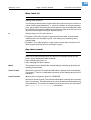
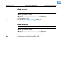
Operating the parameter menu
The illustrations on the following pages clarifie the operating principle of the
parameter menu. The return path shown on the left of the screen, called up
using the Prog. button, also applies for parameters in the middle of the
screen.
Setting values
The setting of a parameter always follows this scheme:
1. Select the parameter.
2. Press the Online button.
3. Set the parameter to the intended value by pressing the Cut or Feed button.
4. Confirm by pressing the Online button.
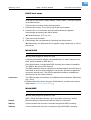
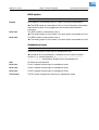
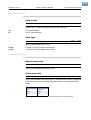
Example
Setting the parameter PRINT PARAMETERS > Material type to punched material.
Action
Display
OFFLINE
Note
0 JOBS
1. Press Prog button.
PRINT INFO
2. Press Cut button.
PRINT PARAMETERS
3. Press Online button.
PRINT PARAMETERS
Print speed
4. Press Cut button several PRINT PARAMETERS
Initial state: off-line mode.
First menu item of the
"PRINT PARAMETERS"
menu.
Parameter selected.
times, up to the display: Material type
5. Press Online button.
Material type
Endless
6. Press Feed button.
Material type
Punched
Setting the parameter to
the intended value by
pressing the Cut or Feed
button.
7. Press Online button.
PRINT PARAMETERS
Material type
Confirm with Online button.
8. Press Prog button 2x.
OFFLINE
"Way back" by pressing
the Prog button.
0 JOBS
Tab. 1:Example for setting a parameter: Changing the material type setting.
8
09/09 Rev. 5.03-01
USER- / SERVICE MANUAL
Info-Printouts & Parameters
AP 4.4 – AP 5.4 – AP 7.t
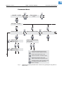
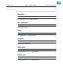
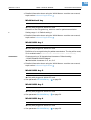
Parameter Menu
ONLINE 0 JOBS
Print contrast
65 %
OFFLINE 0 JOBS
PRINT INFO
PRINT PARAMETERS
PRINT INFO
Printer status
PRINT PARAMETERS
Print speed
INTERF. PARAM.
PRINT INFO
Memory status
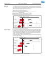
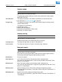
Scrolls down through the menu and
selects menu items. Reduces values.
Scrolls up through the menu and
selects menu items. Increases values.
Selects the parameter menu from
offline mode. Returns to previous menu.
Switches between online and offline mode
or confirms menu items, values and
status messages.
Fig. 1:
Guideline through the parameter menu. Start into it by pressing the Prog button in
off-line mode.
9
09/09 Rev. 5.03-01
USER- / SERVICE MANUAL
64-xx – DPM – PEM – ALX 92x – AP 4.4 – AP 5.4 – AP 7.t
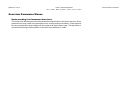
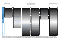
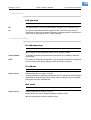
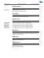
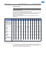
Overview Parameter Menus
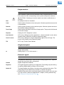
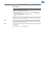
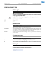
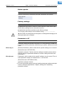
Understanding the Parameter Overviews
The charts in the following show all of the parameters implemented in the printer firmware. Some
parameters are only visible in the parameter menu under specific preconditions. These parameters are provided with a gray background and a digit at the right column edge. The digit refers to
a footnote describing the precondition under which the parameter is visible.
Info-Printouts & Parameters
10
09/09 Rev. 5.03-01
USER- / SERVICE MANUAL
Info-Printouts & Parameters
AP 4.4 – AP 5.4 – AP 7.t
FW 3.33
AP 5.4 Parameters
AP
5.4 INFO
Parameter
PRINT
Printer status
Memory status
Font status
Flashdata status
Service status
Dottest endless
Dottest punched
Reference label
RFID status
4
22
PRINT PARAMETERS
INTERFACE PARA
(INTERFACE PARA cont.)
(INTERFACE PARA cont.)
SYSTEM PARAMETER
Print speed
Feed speed
Material type
Material length
Material width
Print direction
Punch offset
Bar code Multi.
Tradit. Imaging
UPC plain-copy
EAN Readline
EAN sep. lines
Cut mode
Cut position
Double cut
Rewind direction
Rotated barcodes
X – Printadjust
Y – Printadjust
Punch mode
Punch level
> EASYPLUGINTERPR
Interface
Spooler mode
Printer ID No.
Spooler size
Offline mode
Interface delay
Parity
Stop bits
Data synch.
Frame error
WLAN 128Bit key 2
WLAN 128Bit key 3
WLAN 128Bit key 4
WLAN com quality
WLAN signal lev.
Foil end warning
Foil warn stop
Print Interpret.
Character sets
Character filter
Light sens. type
Head-sensor dist
Sens. punch-LS
Foil mode
Turn-on mode
Error reprint
EasyPlug errors
Single job mode
Head resistance
Temp. reduction
Thin line emphas
Voltage offset
Miss. label tol.
Gap detect mode
Periph. device
Singlestartquant
Start mode
External signal
Signal edge
Print contrast
Ram disk size
Font downl. area
Free store size
1/13
6
6
6
5
12
> CENTRONICS
PnP function
> COM1 PORT
Baud rate
No. of data bits
Parity
Stop bits
Data synch.
Frame error
> COM2 PORT
Baud rate
No. of data bits
Parity
Stop bits
Data synch.
Frame error
Serial Port Mode
> COM3 PORT
Baud rate
No. of data bits
23
23
23
23
23
23
23
23
> NETWORK PARAM.
IP Addressassign
IP Address
Net mask
Gateway address
Port address
Ethernet speed
MAC address
FTP server
FTP password
WEB server
DHCP host name
WLAN SSID
WLAN WEP
WLAN default key
WLAN 64Bit key 1
WLAN 64Bit key 2
WLAN 64Bit key 3
WLAN 64Bit key 4
WLAN 128Bit key 1
> OPTIONS
Remote Display
RFID Option
StandAlone Input
13
31
31
31
31
31
31
31
31
31
31
31
31
31
18
13/14
13
24
1. Only with PRINT PARAMETERS > Bar code Multi. = „ yes“ 2. Only with BLDC firmware version V4-T36 or higher 4. Only with at least one data block stored in the flash memory 5. Only with rewinder option
6. Only with cutter 7. Only with „AP 5.4 peripheral“ 10. Only with activated MONARCH LANGUAGE INTERPRETER™ 12. Only if PRINT PARAMETERS > Punch mode = Manual 13. Only in production mode
14. As in 13. or with a setting value > 0 18. Only with installed RFID option 20. Only if SYSTEM PARAMETERS > Periph. device = Dispenser 21. Only if SYSTEM PARAMETERS > Periph. device = Int Rewinder
22. Only with an activated RFID option 23. Only with I/O board 24. Not with I/O board 29. Availability depends on device configuration 30. Only with a CF card inserted 31. Only with WLAN CF card inserted
11
09/09 Rev. 5.03-01
USER- / SERVICE MANUAL
Info-Printouts & Parameters
(SYSTEM PARAM. cont.)
I/O BOARD PARA
23
MLI PARAMETERS
10
DISPENSER PARA
Print info mode
Reprint function
Language
Keyboard
Access authoriz.
Realtime Clock
Start delay
Start print mode
Reprint Signal
Feed input
Pause input
Error output
Error polarity
Status output
Status polarity
End print mode
23
23
23
23
23
23
23
23
23
23
Version
Darkness
Control Prefix
Format Prefix
Delimiter Char
Label Top
Left Position
Manual Calibrate
Resolution
Error Indication
Error Checking
305 DPI Scaling
Image Save Path
Command ^PR
Command ^MT
Label Invert
Command ^JM
10
10
10
10
10
10
10
10
10
10
10
10
10
10
10
10
10
Dispense Mode
Dispenseposition
Display mode
Dispense counter
Application mode
Start mode
Start source
Calibration mode
Current mode
Min rew. current
Max rew. current
Start rew. curr.
Start cur. len.
Pullback current
Back diameter
Break current
Break diameter
20
20
20
20
20
20
20
20
20
13+20
13+20
13+20
13+20
13+20
13+20
13+20
13+20
13+20
REWINDER PARA
Rewind direction
Start mode
Current mode
Min rew. current
Max rew. current
Start rew. curr.
Start cur. len.
Pullback current
Back diameter
Break current
Break diameter
21
21
21
13+21
13+21
13+21
13+21
13+21
13+21
13+21
13+21
13+21
SPECIAL FUNCTION
Command sequence
Default values
Delete job
Delete spooler
Factory settings
Parameter to CF
Diagnosis to CF
Data blocks del.
System version
EasyPl. file log
Log files delete
13
13
4
30
30
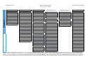
FW 3.33
AP 5.4 Parameters
AP 4.4 – AP 5.4 – AP 7.t
1. Only with PRINT PARAMETERS > Bar code Multi. = „ yes“ 2. Only with BLDC firmware version V4-T36 or higher 4. Only with at least one data block stored in the flash memory 5. Only with rewinder option
6. Only with cutter 7. Only with „AP 5.4 peripheral“ 10. Only with activated MONARCH LANGUAGE INTERPRETER™ 12. Only if PRINT PARAMETERS > Punch mode = Manual 13. Only in production mode
14. As in 13. or with a setting value > 0 18. Only with installed RFID option 20. Only if SYSTEM PARAMETERS > Periph. device = Dispenser 21. Only if SYSTEM PARAMETERS > Periph. device = Int Rewinder
22. Only with an activated RFID option 23. Only with I/O board 24. Not with I/O board 29. Availability depends on device configuration 30. Only with a CF card inserted 31. Only with WLAN CF card inserted
12
09/09 Rev. 5.03-01
USER- / SERVICE MANUAL
Info-Printouts & Parameters
AP 4.4 – AP 5.4 – AP 7.t
FW 3.33
AP 5.4 Parameters
SERVICE FUNCTION
Service
Head exchange
Roller exchange
Cutter exchange
Serv. data reset
EasyPlug monitor
EP Monitor Mode
Sensor adjust
Sensor test
Cutter test
Matend adjust
Matend tolerance
Feedadjust label
Feed adjust
Punch y calibr.
CompactFlashTest
Send test
Receive test
Rewinder adjust
Com2 comun. test
Com2 port test
Print test
13
13
13
13+6
13
23
13
13
13
5
23
23
SERVICE DATA
(Service Data cont.)
> MODULE FW VERS.
System version
System revision
System date
Bootloader
uMon
Peripheraldriver
7
Intern. rewinder
21
> CPU BOARD DATA
CPU identifier
PCB revision
FPGA version
MAC address
Serial number
Production date
PCB part number
Board part numb.
Manufacturer
Work place
Company name
13
13
13
> CF CARD SLOT
Card in slot
Card type
30
> OPERATION DATA
Serv. operations
Headnumber
Roll number
Cutter number
Head run length
Roll run length
Cuts on knife
Tot. mat. length
Tot. foil length
Total cuts
Head strobes
Head temperature
Foil diameter
Operation time
6
6
6
> MEMORY DATA
Ram memory size
Flash mem size
CompactFlash
Space for Jobs
Max. Labellength
Default values
30
> POWERSUPPLYDATA
Type
PS temperature
1. Only with PRINT PARAMETERS > Bar code Multi. = „ yes“ 2. Only with BLDC firmware version V4-T36 or higher 4. Only with at least one data block stored in the flash memory 5. Only with rewinder option
6. Only with cutter 7. Only with „AP 5.4 peripheral“ 10. Only with activated MONARCH LANGUAGE INTERPRETER™ 12. Only if PRINT PARAMETERS > Punch mode = Manual 13. Only in production mode
14. As in 13. or with a setting value > 0 18. Only with installed RFID option 20. Only if SYSTEM PARAMETERS > Periph. device = Dispenser 21. Only if SYSTEM PARAMETERS > Periph. device = Int Rewinder
22. Only with an activated RFID option 23. Only with I/O board 24. Not with I/O board 29. Availability depends on device configuration 30. Only with a CF card inserted 31. Only with WLAN CF card inserted
13
09/09 Rev. 5.03-01
USER- / SERVICE MANUAL
Info-Printouts & Parameters
AP 4.4 – AP 5.4 – AP 7.t
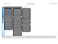
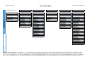
FW 3.33
AP 4.4 Parameters
AP
4.4 INFO
Parameter
PRINT
Printer status
Memory status
Font status
Service status
Dottest endless
Dottest punched
Reference label
PRINT PARAMETERS
INTERFACE PARA
(INTERFACE PARA cont.)
SYSTEM PARAMETER
(SYSTEM PARAM. cont.)
Print speed
Feed speed
Material type
Material length
Material width
Print direction
Punch offset
Bar code Multi.
Tradit. Imaging
UPC plain-copy
EAN Readline
EAN sep. lines
Rotated barcodes
Dispenseposition
X – Printadjust
Y – Printadjust
Punch mode
Punch level
> EASYPLUGINTERPR
Interface
Spooler mode
Printer ID No.
Spooler size
Offline mode
Interface delay
> COM3 PORT
Baud rate
No. of data bits
Parity
Stop bits
Data synch.
Frame error
Reprint function
Language
Keyboard
Access authoriz.
> COM1 PORT
Baud rate
No. of data bits
Parity
Stop bits
Data synch.
Frame error
> CENTRONICS
PnP function
Foil end warning
Foil warn stop
Print Interpret.
Character sets
Character filter
Light sens. type
Head-sensor dist
Sens. punch-LS
Foil mode
Turn-on mode
Error reprint
EasyPlug errors
Single job mode
Head resistance
Temp. reduction
Thin line emphas
Voltage offset
Miss. label tol.
Gap detect mode
Periph. device
Singlestartquant
Start mode
External signal
Print contrast
Ram disk size
Font downl. area
Free store size
Print info mode
1/13
12
> COM2 PORT
Baud rate
No. of data bits
Parity
Stop bits
Data synch.
Serial port mode
Frame error
> OPTIONS
Remote Display
StandAlone Input
13/14
13
1. Only with PRINT PARAMETERS > Bar code Multi. = „ yes“ 2. Only with BLDC firmware version V4-T36 or higher 4. Only with at least one data block stored in the flash memory 5. Only with rewinder option
6. Only with cutter 7. Only with „AP 5.4 peripheral“ 10. Only with activated MONARCH LANGUAGE INTERPRETER™ 12. Only if PRINT PARAMETERS > Punch mode = Manual 13. Only in production mode
14. As in 13. or with a setting value > 0 18. Only with installed RFID option 20. Only if SYSTEM PARAMETERS > Periph. device = Dispenser 21. Only if SYSTEM PARAMETERS > Periph. device = Int Rewinder
22. Only with an activated RFID option 23. Only with I/O board 24. Not with I/O board 29. Availability depends on device configuration 30. Only with a CF card inserted 31. Only with WLAN CF card inserted
14
09/09 Rev. 5.03-01
USER- / SERVICE MANUAL
Info-Printouts & Parameters
AP 4.4 Parameters
AP 4.4 – AP 5.4 – AP 7.t
MLI PARAMETERS
10
SPECIAL FUNCTION
Version
Darkness
Control Prefix
Format Prefix
Delimiter Char
Label Top
Left Position
Manual Calibrate
Resolution
Error Indication
Error Checking
Image Save Path
Command ^PR
Command ^MT
Label Invert
Command ^JM
10
10
10
10
10
10
10
10
10
10
10
10
10
10
10
10
Command sequence
Default values
Delete job
Delete spooler
Factory settings
Parameter to CF
SERVICE FUNCTION
13
13
Service
Head exchange
Roller exchange
Serv. data reset
EasyPlug monitor
EP Monitor Mode
Sensor adjust
Sensor test
Cutter test
Matend adjust
Matend tolerance
Feedadust label
Feed adjust
Punch y calibr.
CompactFlashTest
Send test
Receive test
Com2 comun. test
Com2 port test
Print test
13
13
13
13
23
13
13
13
23
23
SERVICE DATA
(SERVICE DATA cont.)
> MODULE FW VERS.
System version
System revision
System date
Bootloader
uMon
MAC address
Serial number
Production date
PCB part number
Board part numb.
Manufacturer
Work place
Company name
> OPERATION DATA
Serv. operations
Headnumber
Roll number
Head run length
Roll run length
Tot. mat. length
Tot. foil length
Head strobes
Head temperature
Foil diameter
Operation time
13
13
13
> CF CARD SLOT
Card in slot
> MEMORY DATA
Ram memory size
Flash mem size
Space for Jobs
Max. Labellength
Default values
FW 3.33
> POWERSUPPLYDATA
Type
PS temperature
> CPU BOARD DATA
CPU identifier
PCB revision
FPGA version
1. Only with PRINT PARAMETERS > Bar code Multi. = „ yes“ 2. Only with BLDC firmware version V4-T36 or higher 4. Only with at least one data block stored in the flash memory 5. Only with rewinder option
6. Only with cutter 7. Only with „AP 5.4 peripheral“ 10. Only with activated MONARCH LANGUAGE INTERPRETER™ 12. Only if PRINT PARAMETERS > Punch mode = Manual 13. Only in production mode
14. As in 13. or with a setting value > 0 18. Only with installed RFID option 20. Only if SYSTEM PARAMETERS > Periph. device = Dispenser 21. Only if SYSTEM PARAMETERS > Periph. device = Int Rewinder
22. Only with an activated RFID option 23. Only with I/O board 24. Not with I/O board 29. Availability depends on device configuration 30. Only with a CF card inserted 31. Only with WLAN CF card inserted
15
09/09 Rev. 5.03-01
USER- / SERVICE MANUAL
Info-Printouts & Parameters
AP 4.4 – AP 5.4 – AP 7.t
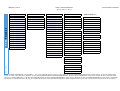
FW 3.33
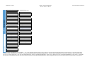
AP 7.t Parameters
AP
7.t Parameter
PRINT
INFO
Printer status
Memory status
Font status
Flashdata status
Textile care sym
Service status
Dottest endless
Dottest punched
Reference Label
4
PRINT PARAMETERS
INTERFACE PARA
(INTERFACE PARA cont.)
(INTERFACE PARA cont.)
SYSTEM PARAMETER
Print speed.
Feed speed.
Material type
Material length
Material width
Print direction
Punch offset
Bar code Multi.
Tradit. Imaging
UPC plain-copy
EAN Readline
EAN sep. lines
Cut speed.
Cut position
Double cut
Rotated barcodes
X – Printadjust
Y – Printadjust
Punch mode
Punch level
>EASYPLUGINTERPR
Interface
Spooler mode
Printer ID no.
Spooler size
Offline mode
Interface delay
Parity
Stop bits
Data synch.
Frame error
WLAN 64Bit key 4
WLAN 128Bit key 1
WLAN 128Bit key 2
WLAN 128Bit key 3
WLAN 128Bit key 4
WLAN com quality
WLAN signal lev.
>COM1 PORT
Baud rate
No. of data bits
Parity
Stop bits
Data synch.
Frame error
> NETWORK PARAM.
IP Addressassign
IP Address
Net mask
Gateway address
Port address
Ethernet speed
MAC address
SNMP agent
SNMP password
FTP server
FTP password
WEB server
DHCP host name
WLAN SSID
WLAN WEP
WLAN default key
WLAN 64Bit key 1
WLAN 64Bit key 2
WLAN 64Bit key 3
Foil end warning
Foil warn stop
Print Interpret.
Character sets
Character filter
Licht sens. type
Head-sensor dist
Sens. punch-LS
Ribbon autoecon.
Ribbon eco. limit
Feed mode
Turn-on mode
Error reprint
EasyPlug errors
Single job mode
Head resistance
Temp. reduction
Voltage offset
Miss. label tol.
Gap detect mode
Periph. device
Singlestartquant
External signal
Signal edge
Print contrast
Ram disk size
Font downl. area
Free store size
1/13
6
6
6
12
>COM2 PORT
Baud rate
No. of data bits
Parity
Stop bits
Data synch.
Frame error
Serial Port Mode
>COM3 PORT
Baud rate
No. of data bits
>CENTRONICS
PnP function
23
23
23
23
23
23
23
23
> OPTIONS
Remote Display
StandAlone Input
13
13
31
31
31
31
31
31
31
31
31
31
31
31
31
13/14
24
1. Only with PRINT PARAMETERS > Bar code Multi. = „ yes“ 2. Only with BLDC firmware version V4-T36 or higher 4. Only with at least one data block stored in the flash memory 5. Only with rewinder option
6. Only with cutter 7. Only with „AP 5.4 peripheral“ 10. Only with activated MONARCH LANGUAGE INTERPRETER™ 12. Only if PRINT PARAMETERS > Punch mode = Manual 13. Only in production mode
14. As in 13. or with a setting value > 0 18. Only with installed RFID option 20. Only if SYSTEM PARAMETERS > Periph. device = Dispenser 21. Only if SYSTEM PARAMETERS > Periph. device = Int Rewinder
22. Only with an activated RFID option 23. Only with I/O board 24. Not with I/O board 29. Availability depends on device configuration 30. Only with a CF card inserted 31. Only with WLAN CF card inserted
16
09/09 Rev. 5.03-01
USER- / SERVICE MANUAL
Info-Printouts & Parameters
(SYSTEM PARAM. cont.)
I/O BOARD PARA
23
MLI PARAMETERS
10
TEXTILE PARAMETE
SPECIAL FUNCTION
Print Info Mode
Reprint function
Language
Keyboard
Access authoriz.
Realtime clock
Start delay
Start print mode
Reprint signal
Feed
Pause input
Error output
Error polarity
Status output
Status polarity
End print mode
23
23
23
23
23
23
23
23
23
23
Version
Darkness
Control Prefix
Format Prefix
Delimiter Char
Label Top
Left Position
Manual Calibrate
Resolution
Error Indication
Error Checking
305 DPI Scaling
Image Save Path
Command ^PR
Command ^MT
Label Invert
Command ^JM
10
10
10
10
10
10
10
10
10
10
10
10
10
10
10
10
10
Changelabel Mode
Changelab Print
Changelab Length
Label Eject Mode
Head lift autom.
Head clean
Printer type
Default values
Command Sequence
Delete job
Delete spooler
Factory settings
Parameter to CF
Data blocks del.
System version
EasyPl. file log
Log files delete
SERVICE FUNCTION
13
13
13
4
30
30
Service
Head exchange
Roller exchange
Cutter exchange
Serv. data reset
EasyPlug monitor
EP Monitor Mode
Head adjust
Sensor adjust
Sensor test
Cutter test
Matend adjust
Matend tolerance
Feedadjust label
Feed adjust
Punch y calibr.
CompactFlashTest
Send test
Receive test
Rewinder adjust
Com2 comun. test
Com2 port test
Print test
13
13
13
13+6
13
13
13
13
13
5
23
23
FW 3.33
AP 7.t Parameters
AP 4.4 – AP 5.4 – AP 7.t
1. Only with PRINT PARAMETERS > Bar code Multi. = „ yes“ 2. Only with BLDC firmware version V4-T36 or higher 4. Only with at least one data block stored in the flash memory 5. Only with rewinder option
6. Only with cutter 7. Only with „AP 5.4 peripheral“ 10. Only with activated MONARCH LANGUAGE INTERPRETER™ 12. Only if PRINT PARAMETERS > Punch mode = Manual 13. Only in production mode
14. As in 13. or with a setting value > 0 18. Only with installed RFID option 20. Only if SYSTEM PARAMETERS > Periph. device = Dispenser 21. Only if SYSTEM PARAMETERS > Periph. device = Int Rewinder
22. Only with an activated RFID option 23. Only with I/O board 24. Not with I/O board 29. Availability depends on device configuration 30. Only with a CF card inserted 31. Only with WLAN CF card inserted
17
09/09 Rev. 5.03-01
USER- / SERVICE MANUAL
Info-Printouts & Parameters
FW 3.33
AP 7.t Parameters
AP 4.4 – AP 5.4 – AP 7.t
SERVICE DATA
(SERVICE DATA cont.)
> MODULE FW VERS.
System version
System revision
System date
Bootloader
uMon
Feed driver
Head driver
Peripheraldriver
> CPU BOARD DATA
CPU identifier
PCB revision
> OPERATION DATA
Serv. operations
Headnumber
Roll number
Cutter number
Head run length
Roll run length
Cuts on knife
Tot. mat. length
Tot. foil length
Total cuts
Total head moves
Head strobes
Foil diameter
Operation time
FPGA version
MAC address
Serial number
Production date
PCB part number
Board part numb.
Manufacturer
Work place
Company name
6
> CF CARD SLOT
Card in slot
6
> MEMORY DATA
Ram memory size
Flash mem size
Space for Jobs
Max. Labellength
Default values
6
13
13
13
> POWERSUPPLYDATA
Type
1. Only with PRINT PARAMETERS > Bar code Multi. = „ yes“ 2. Only with BLDC firmware version V4-T36 or higher 4. Only with at least one data block stored in the flash memory 5. Only with rewinder option
6. Only with cutter 7. Only with „AP 5.4 peripheral“ 10. Only with activated MONARCH LANGUAGE INTERPRETER™ 12. Only if PRINT PARAMETERS > Punch mode = Manual 13. Only in production mode
14. As in 13. or with a setting value > 0 18. Only with installed RFID option 20. Only if SYSTEM PARAMETERS > Periph. device = Dispenser 21. Only if SYSTEM PARAMETERS > Periph. device = Int Rewinder
22. Only with an activated RFID option 23. Only with I/O board 24. Not with I/O board 29. Availability depends on device configuration 30. Only with a CF card inserted 31. Only with WLAN CF card inserted
18
09/09 Rev. 5.03-01
USER- / SERVICE MANUAL
Info-Printouts & Parameters
AP 4.4 – AP 5.4 – AP 7.t
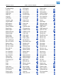
Alphabetical Parameter List
Access authoriz. . . . . . . . . . . . 74
Application mode . . . . . . . . . . 83
Back diameter. . . . . . . . . . . . . 87
Back diameter. . . . . . . . . . . . . 90
Bar code multip. . . . . . . . . . . . 35
Baud rate . . . . . . . . . . . . . . . . 45
Baud rate . . . . . . . . . . . . . . . . 46
Baud rate . . . . . . . . . . . . . . . . 48
Board part numb. . . . . . . . . 116
Bootloader . . . . . . . . . . . . . 111
Brake current . . . . . . . . . . . . . 88
Brake current . . . . . . . . . . . . . 90
Brake diameter . . . . . . . . . . . . 88
Break diameter . . . . . . . . . . . . 91
Calibration mode. . . . . . . . . . . 84
Card in slot . . . . . . . . . . . . . 117
Card type . . . . . . . . . . . . . . 117
Changelab Length . . . . . . . . . 96
Changelab Print . . . . . . . . . . . 96
Changelabel mode . . . . . . . . . 96
Character filter . . . . . . . . . . . . 63
Character sets . . . . . . . . . . . . 62
Com2 commun. test . . . . . . 110
Com2 port test . . . . . . . . . . 110
Command ^JM. . . . . . . . . . . . 95
Command ^MT . . . . . . . . . . . 95
Command ^PR . . . . . . . . . . . 94
Command sequence. . . . . . . . 98
CompactFlash. . . . . . . . . . . 118
CompactFlashTest . . . . . . . 106
Company name . . . . . . . . . 116
Control Prefix . . . . . . . . . . . . . 92
CPU identifier . . . . . . . . . . . 115
Current mode . . . . . . . . . . . . . 85
Current mode . . . . . . . . . . . . . 89
Cut mode . . . . . . . . . . . . . . . . 38
Cut position. . . . . . . . . . . . . . . 40
Cut speed . . . . . . . . . . . . . . . . 40
Cuts on knife. . . . . . . . . . . . 113
Cutter exchange. . . . . . . . . . 103
Cutter number . . . . . . . . . . . 112
Cutter test. . . . . . . . . . . . . . . 104
Darkness . . . . . . . . . . . . . . . . 92
Data blocks del. . . . . . . . . . . 100
Data synch. . . . . . . . . . . . . . . 46
Data synch. . . . . . . . . . . . . . . 47
Data synch. . . . . . . . . . . . . . . 48
Default values. . . . . . . . . . . . 118
Default Values . . . . . . . . . . . . 98
Delete job . . . . . . . . . . . . . . . . 98
Delete spooler . . . . . . . . . . . . 99
Delimiter Char . . . . . . . . . . . . 93
DHCP host name . . . . . . . . . . 55
Diagnosis to CF . . . . . . . . . . 100
Dispense counter . . . . . . . . . . 83
Dispense Mode . . . . . . . . . . . 81
Dispenseposition . . . . . . . . . . 82
Dispensing cycl. . . . . . . . . . . 114
Display mode . . . . . . . . . . . . . 83
Dottest endless. . . . . . . . . . . . 30
Dottest punched . . . . . . . . . . . 30
Double cut . . . . . . . . . . . . . . . 40
EAN Readline. . . . . . . . . . . . . 36
EAN sep. lines . . . . . . . . . . . . 37
EasyPl. file log . . . . . . . . . . . 101
EasyPlug error . . . . . . . . . . . . 65
EasyPlug monitor . . . . . . . . . 103
End print mode. . . . . . . . . . . . 80
EP Monitor Mode . . . . . . . . . 104
Error Checking . . . . . . . . . . . . 94
Error Indication. . . . . . . . . . . . 94
Error output . . . . . . . . . . . . . . 79
Error Polarity . . . . . . . . . . . . . 79
Error reprint . . . . . . . . . . . . . . 65
Ethernet speed. . . . . . . . . . . . 50
External signal . . . . . . . . . . . . 69
Factory settings . . . . . . . . . . . 99
Feed adjust. . . . . . . . . . . . . . 106
Feed driver. . . . . . . . . . . . . . 111
Feed input . . . . . . . . . . . . . . . 78
Feed mode. . . . . . . . . . . . . . . 65
Feed speed . . . . . . . . . . . . . . 32
Feedadjust label . . . . . . . . . 105
Flash mem size . . . . . . . . . . 117
Flashdata status . . . . . . . . . . 27
Foil diameter . . . . . . . . . . . . 114
Foil end warning . . . . . . . . . . 60
Foil mode . . . . . . . . . . . . . . . . 65
Foil warn stop . . . . . . . . . . . . 60
Font downl. area . . . . . . . . . . 72
Font status . . . . . . . . . . . . . . . 24
Format Prefix . . . . . . . . . . . . . 93
FPGA version . . . . . . . . . . . 115
Frame error . . . . . . . . . . . . . . 46
Frame error . . . . . . . . . . . . . . 47
Frame error . . . . . . . . . . . . . . 48
Free store size . . . . . . . . . . . . 73
FTP password . . . . . . . . . . . . 51
FTP server . . . . . . . . . . . . . . . 51
Gap detect mode . . . . . . . . . . 68
Gateway address. . . . . . . . . . 50
Head adjust . . . . . . . . . . . . . 104
Head clean. . . . . . . . . . . . . . . 97
Head driver . . . . . . . . . . . . . 111
Head exchange . . . . . . . . . . 102
Head lift autom. . . . . . . . . . . . 97
Head resistance. . . . . . . . . . . 66
Head run length . . . . . . . . . . 113
Head strobes . . . . . . . . . . . . 114
Head temperature . . . . . . . . 114
Headnumber . . . . . . . . . . . . 112
Head-sensor dist.. . . . . . . . . . 63
Image Save Path . . . . . . . . . . 94
Interface delay . . . . . . . . . . . . 44
Interface. . . . . . . . . . . . . . . . . 43
Intern. rewinder . . . . . . . . . . 112
IP address . . . . . . . . . . . . . . . 49
19
09/09 Rev. 5.03-01
USER- / SERVICE MANUAL
Info-Printouts & Parameters
AP 4.4 – AP 5.4 – AP 7.t
IP addressassign . . . . . . . . . . 49
Keyboard . . . . . . . . . . . . . . . . 74
Label eject mode . . . . . . . . . . 97
Label Invert . . . . . . . . . . . . . . . 95
Label Top . . . . . . . . . . . . . . . . 93
Language . . . . . . . . . . . . . . . . 74
Left Position . . . . . . . . . . . . . . 93
Light sens. type. . . . . . . . . . . . 63
Log files delete . . . . . . . . . . 101
MAC address . . . . . . . . . . . 115
MAC address . . . . . . . . . . . . . 50
Manual Calibrate. . . . . . . . . . . 93
Manufacturer. . . . . . . . . . . . 116
Matend adjust . . . . . . . . . . . 105
Matend tolerance . . . . . . . . 105
Material length . . . . . . . . . . . . 33
Material type . . . . . . . . . . . . . . 32
Material width . . . . . . . . . . . . . 33
Max rew. current . . . . . . . . . . . 89
Max. Labellength . . . . . . . . 118
Max. rew. current . . . . . . . . . . 86
Memory status . . . . . . . . . . . . 23
Min. rew. current . . . . . . . . . . . 85
Min. rew. current . . . . . . . . . . . 89
Miss. label tol. . . . . . . . . . . . . . 68
Net mask. . . . . . . . . . . . . . . . . 49
No. of data bits . . . . . . . . . . . . 45
No. of data bits . . . . . . . . . . . . 46
No. of data bits . . . . . . . . . . . . 48
Offline mode . . . . . . . . . . . . . . 44
Operation time . . . . . . . . . . 114
Parameter to CF . . . . . . . . . . . 99
Parity. . . . . . . . . . . . . . . . . . . . 45
Parity. . . . . . . . . . . . . . . . . . . . 46
Parity. . . . . . . . . . . . . . . . . . . . 48
Pause input. . . . . . . . . . . . . . . 78
PCB part number . . . . . . . . 116
PCB revision . . . . . . . . . . . . 115
Periph. device . . . . . . . . . . . . . 69
Peripheraldriver . . . . . . . . . 112
PnP function. . . . . . . . . . . . . . 49
Port address. . . . . . . . . . . . . . 50
Print contrast . . . . . . . . . . . . . 71
Print direction . . . . . . . . . . . . . 34
Print info mode . . . . . . . . . . . . 73
Print Interpret.. . . . . . . . . . . . . 61
Print speed . . . . . . . . . . . . . . . 32
Printer ID No. . . . . . . . . . . . . . 44
Printer status . . . . . . . . . . . . . 21
Printer type. . . . . . . . . . . . . . . 98
Printtest . . . . . . . . . . . . . . . . 110
Production date . . . . . . . . . . 116
PS temperature . . . . . . . . . . 115
Pullback current . . . . . . . . . . . 87
Pullback current . . . . . . . . . . . 90
Punch level. . . . . . . . . . . . . . . 42
Punch mode . . . . . . . . . . . . . . 42
Punch offset . . . . . . . . . . . . . . 35
Punch y calibr. . . . . . . . . . . . 106
Ram disk size. . . . . . . . . . . . . 72
Ram memory size . . . . . . . . 117
Realtime clock . . . . . . . . . . . . 76
Receive test . . . . . . . . . . . . . 108
Reference label . . . . . . . . . . . 31
Remote Display . . . . . . . . . . . 58
Reprint function . . . . . . . . . . . 73
Reprint Signal. . . . . . . . . . . . . 78
Resolution . . . . . . . . . . . . . . . 94
Rewind direction. . . . . . . . . . . 41
Rewind direction. . . . . . . . . . . 89
Rewinder adjust . . . . . . . . . . 109
RFID Option . . . . . . . . . . . . . . 59
RFID stat. del. . . . . . . . . . . . 101
Ribbon autoecon. . . . . . . . . . . 64
Roll number . . . . . . . . . . . . . 112
Roll run length . . . . . . . . . . . 113
Roller exchange . . . . . . . . . . 102
Rotated Barcodes. . . . . . . . . . 37
Send test . . . . . . . . . . . . . . . 107
Sens. punch-LS . . . . . . . . . . . 64
Sensor adjust. . . . . . . . . . . . 104
Sensor test . . . . . . . . . . . . . 104
Serial number . . . . . . . . . . . 115
Serial Port Mode . . . . . . . . . . 47
Serv. data reset . . . . . . . . . . 103
Serv. operations. . . . . . . . . . 112
Service Status . . . . . . . . . . . . 29
Service. . . . . . . . . . . . . . . . . 102
Signal edge . . . . . . . . . . . . . . 71
Single job mode . . . . . . . . . . . 66
Singlestartquant. . . . . . . . . . . 69
SNMP agent . . . . . . . . . . . . . 50
SNMP password . . . . . . . . . . 50
Space for Jobs. . . . . . . . . . . 118
Spooler mode . . . . . . . . . . . . 43
Spooler size . . . . . . . . . . . . . . 44
StandAlone Input . . . . . . . . . . 59
Start cur. len. . . . . . . . . . . . . . 87
Start cur. len. . . . . . . . . . . . . . 90
Start delay . . . . . . . . . . . . . . . 77
Start mode . . . . . . . . . . . . . . . 70
Start mode . . . . . . . . . . . . . . . 84
Start mode . . . . . . . . . . . . . . . 89
Start print mode . . . . . . . . . . . 77
Start rew. curr. . . . . . . . . . . . . 90
Start rew. current . . . . . . . . . . 86
Start source . . . . . . . . . . . . . . 84
Status output . . . . . . . . . . . . . 80
Status polarity . . . . . . . . . . . . 80
Stop bits. . . . . . . . . . . . . . . . . 45
Stop bits. . . . . . . . . . . . . . . . . 47
Stop bits. . . . . . . . . . . . . . . . . 48
Sync. Interval . . . . . . . . . . . . . 54
System date. . . . . . . . . . . . . 111
System revision . . . . . . . . . . 111
System version . . . . . . . . . . 111
Temp. reduction. . . . . . . . . . . 67
Textile care sym. . . . . . . . . . . 28
Thin line emphas . . . . . . . . . . 67
Time client . . . . . . . . . . . . . . . 54
20
09/09 Rev. 5.03-01
USER- / SERVICE MANUAL
AP 4.4 – AP 5.4 – AP 7.t
Time server IP . . . . . . . . . . . . 54
Tot. foil length . . . . . . . . . . . 113
Tot. mat. length. . . . . . . . . . 113
Total cuts . . . . . . . . . . . . . . 113
Total head moves . . . . . . . . 114
Tradit. Imaging . . . . . . . . . . . . 36
Turn-on mode . . . . . . . . . . . . . 65
Type . . . . . . . . . . . . . . . . . . 115
uMon. . . . . . . . . . . . . . . . . . 111
UPC plain-copy. . . . . . . . . . . . 36
Version . . . . . . . . . . . . . . . . . . 92
Voltage offset . . . . . . . . . . . . . 67
WEB admin passw.. . . . . . . . . 53
WEB display refr . . . . . . . . . . . 53
WEB server. . . . . . . . . . . . . . . 52
WEB supervisor p. . . . . . . . . . 53
WLAN 128Bit key 1. . . . . . . . . 57
WLAN 128Bit key 2. . . . . . . . . 57
WLAN 128Bit key 3. . . . . . . . . 57
WLAN 128Bit key 4. . . . . . . . . 57
WLAN 64Bit key 1. . . . . . . . . . 56
WLAN 64Bit key 2. . . . . . . . . . 56
WLAN 64Bit key 3. . . . . . . . . . 56
WLAN 64Bit key 4. . . . . . . . . . 56
WLAN com quality . . . . . . . . . 57
WLAN default key . . . . . . . . . . 56
WLAN signal lev. . . . . . . . . . . 58
WLAN SSID . . . . . . . . . . . . . . 55
WLAN WEP . . . . . . . . . . . . . . 55
Work place . . . . . . . . . . . . . 116
X - Printadjust . . . . . . . . . . . . . 41
Y – Printadjust . . . . . . . . . . . . 41
Info-Printouts & Parameters
21
09/09 Rev. 5.03-01
USER- / SERVICE MANUAL
Info-Printouts & Parameters
AP 4.4 – AP 5.4 – AP 7.t
PRINT INFO
¯ Printing of individual reports can be deactivated for certain options (e. g.
for the infeed option).
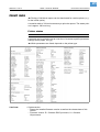
A material width of 100 mmis necessary to print the reports. The status printout is approx. 200 mm long.
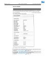
Printer status
AP 4.4
AP 5.4
AP 7.t
A protocol can be printed to get an overview of customer-specific parameter
settings (three pages, see [1]).
¯ Which parameters are listed, depends on the printer type.
[1]
Listed items:
Three pages printer status printout with a 64-05 with firmware version 2.46.
y Systemversion:
– Shows the installed firmware version as well as the release date of this
version.
– Firmware version: R = firmware RISC processor, H = firmware
H8 processor.
22
09/09 Rev. 5.03-01
USER- / SERVICE MANUAL
Info-Printouts & Parameters
AP 4.4 – AP 5.4 – AP 7.t
y Printer type:
– Shows the printer type, which has been set using parameter
SERVICE FUNCTIONS > printer type (e.g. Avery 64-04)
– "USA" displayed after the printer type indicates that the USA font is loaded.
– "8DOT" displayed after the printer type indicates that the 8-Dot emulation
is loaded.
y Printer Parameter Menu
Shows the setting of the parameters in the PRINT PARAMETERS menu.
y Printer Interface Menu
Shows the setting of the parameters in the INTERFACE PARA menu.
y Printer system menu
Shows the setting of the parameters in the SYSTEM PARAMETERS menu.
y Dispenser Interface
Shows the setting of the parameters in the DP INTERFACE menu.
y Internal Options
– Default values: Shows the values which are used in case of a factory reset
(Standard or Default). See parameter SPECIAL FUNCTION > Default Values.
– Realtime Clock: Shows the set time and date, if a realtime clock is installed.
In case of a too low battery, the line "Battery empty" is added.
– 2. com port: Shows if an additionall serial Interface is installed (not
supported).
23
09/09 Rev. 5.03-01
USER- / SERVICE MANUAL
Info-Printouts & Parameters
AP 4.4 – AP 5.4 – AP 7.t
Memory status
AP 4.4
AP 5.4
AP 7.t
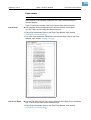
A memory protocol can be printed to provide an overview of the distribution
of the available memory capacity (one page).
[2]
Listed items:
Example of a memory Status printout.
y Internal Memory Configuration
P See paragraph > MEMORY DATA
on page 117.
y Logos on RAM disc
y Graphics on RAM disc
y Fonts on RAM disc
P See Plug-in card manual , topic section „Application“, chapter „CompactFlash card“.
24
09/09 Rev. 5.03-01
USER- / SERVICE MANUAL
Info-Printouts & Parameters
AP 4.4 – AP 5.4 – AP 7.t
Font status
AP 4.4
AP 5.4
AP 7.t
Print samples of all installed characters, bar codes and line samples
(several pages).
Page „Font Library“ shows a list of the internal fonts and line styles.
Internal Fonts
« Use the Easy-Plug commands listet in the first column of the report
(e.g. #YT100), to print using the appropriate font.
P Easy Plug commands: Refer to the Easy Plug Manual, topic section
Description of Commands .
P For a list of all characters contained in the internal fonts, refer to the User
Manual, topic section Internal Fonts .
[3]
Internal Line Styles
Print sample of internal fonts and line styles.
« Use the line style number (fist column) with one of the Easy Plug commands
#YL or #YR to print lines in the matching style.
P Easy Plug commands: Refer to the Easy Plug Manual, topic section
Description of Commands .
25
09/09 Rev. 5.03-01
USER- / SERVICE MANUAL
Info-Printouts & Parameters
AP 4.4 – AP 5.4 – AP 7.t
¯ Additionally, the following line styles are available:
– 13: Checked pattern with 3 dot edge length
– 14: Checked pattern with 1 mm edge length
– 15: Checked pattern with 5 mm edge length
¯ The line width has to be defined as a multiple of the edge length of the
checked pattern!
Internal bar codes
The pages titled „Barcode Library“ show print samples of the internal bar
codes (see [4], [8]).
[4]
Print sample of internal, onedimensional bar codes.
y Onedimensional bar codes are printed with the Easy-Plug command #YB.
P See manual Easy-Plug, topic section Description of Commands .
y Two-dimensional bar codes are printed by means of special Easy-Plug
commands:
Easy-Plug command Bar code
#IDM
Data Matrix Code
#MXC
Maxi Code
#PDF
PDF 417
#CBF
Codabar F
#CFN
Code 49
[2]
Internal, two-dimensional bar codes.
26
09/09 Rev. 5.03-01
USER- / SERVICE MANUAL
Info-Printouts & Parameters
AP 4.4 – AP 5.4 – AP 7.t
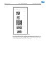
[5]
Print sample of internal, twodimensional bar codes.
y GS1 DataBar (formerly RSS) and Composite Component (CC) bar codes are
printed by means of the Easy-Plug command #RSS. The bar code is
determined by the number in the first column of the subsequent table. This
number is added to the command as a parameter.
27
09/09 Rev. 5.03-01
USER- / SERVICE MANUAL
Info-Printouts & Parameters
AP 4.4 – AP 5.4 – AP 7.t
[6]
Print sample of internal RSS and CC bar codes.
Flashdata status
AP 4.4
AP 5.4
AP 7.t
Prints a list of all fonts stored in the flash memory.
P For details see topic section Internal Fonts , paragraph „Customized fonts“.
28
09/09 Rev. 5.03-01
USER- / SERVICE MANUAL
Info-Printouts & Parameters
AP 4.4 – AP 5.4 – AP 7.t
Textile care sym.
(Textile care symbols)
64-xx
ALX 92x
DPM
PEM
PM 3000
AP 4.4
AP 5.4
AP 7.t
The AP 7.t provides besides the alphanumeric fonts two internal (fix size)
fonts with textile care symbols (font no. 200 and 202).
¯ If any fonts on the Compactflash card are also numbered 200 and/or 202,
those fonts are used by the printer instead of the internal fonts.
Textile Care Sym
[7]
Second page of the info-printout „Textile care symbols“.
29
09/09 Rev. 5.03-01
USER- / SERVICE MANUAL
Info-Printouts & Parameters
AP 4.4 – AP 5.4 – AP 7.t
Service Status
AP 4.4
AP 5.4
AP 7.t
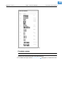
Print the Service status report to read about operation time, no. of services,
no. of exchanged parts and other matters of service interest (one page).
Use the parameter SERVICE FUNCTION > Serv. data reset, to set all the counters to
zero, which are listed on the printout.
[8]
Example of a Service Status printout.
P For information on the operational data on the service status printout refer to
paragraph > OPERATION DATA on page 112.
P For information on the power supply data on the service status printout refer
to paragraph > POWERSUPPLYDATA on page 115.
P For information on the CPU board data on the service status printout refer to
paragraph > CPU BOARD DATA on page 115.
30
09/09 Rev. 5.03-01
USER- / SERVICE MANUAL
Info-Printouts & Parameters
AP 4.4 – AP 5.4 – AP 7.t
P For information on the peripheral driver data on the service status printout
refer to paragraph > MODULE FW VERS. on page 111.
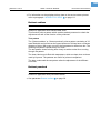
Dottest endless
AP 4.4
AP 5.4
AP 7.t
Dottest for application with endless label stock.
This function prints a pattern which enables trained personnel to check the
adjustment as well as the function of the printhead.
Test pattern
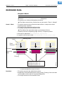
The „Dottest endless“ or „Dottest punched“ prints a pattern consisting of 33
rows filled with vertical lines on the upper label area. All lines have a constant
distance of 4 dot. With every new row, the line pattern is shifted one dot. The
resulting line-pattern repeats every four rows.
The test pattern shows missing dots clearly as white vertical lines running
through the pattern.
The lower label area is filled with testpatterns, which are kept close to those
used by Kyocera. The patterns are useful for printout comparison.
The bars underneath the test pattern allow the adjustment of the different
zero lines.
Dottest punched
AP 4.4
AP 5.4
AP 7.t
Dottest for application with punched material.
P See parameter Dottest endless
on page 30.
31
09/09 Rev. 5.03-01
USER- / SERVICE MANUAL
Info-Printouts & Parameters
AP 4.4 – AP 5.4 – AP 7.t
Reference label
AP 4.4
AP 5.4
AP 7.t
Prints a label with some examples of barcodes, fonts, logos... just try out!
[9]
Example of a Reference label printout.
32
09/09 Rev. 5.03-01
USER- / SERVICE MANUAL
Info-Printouts & Parameters
AP 4.4 – AP 5.4 – AP 7.t
PRINT PARAMETERS
Print speed
AP 4.4
AP 5.4
AP 7.t
The print speed (material feed) can be adjusted according to the ribbon and
material combination being used in order to optimise the contrast depth and
the density of the print image.
x Inch/s
Setting range: see table; Unit interval: 0,2 inch/s;
Default setting: 8 Inch/s
Printer
Print speed
in Inch/s
AP 4.4 / 5.4 / 7.t (8 dot printhead)
2-8
AP 5.4 / 7.t (12 dot printhead)
2-6
[3]
The setting range of the print speed depends on the printhead.
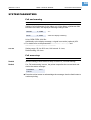
Feed speed
AP 4.4
AP 5.4
AP 7.t
The feed speed can be increased between print periods hereby reducing the
total print time, particularly with long labels with a minimum printed surface.
Setting:
The value for the feed speed should not be set too high for print applications
with long calculating units (e. g. consecutive numbering). This can help to
avoid alternating between abrupt braking to 0 (zero) and acceleration to print
speed.
¯ When altering the print speed, the feed speed is equal to the print speed.
If a different feed speed is required, this must be set again.
x inch/s
Setting range: 2 to 12 inch/s; Unit interval: 1 inch/s
Default setting: 8 inch/s
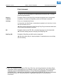
Material type
AP 4.4
AP 5.4
AP 7.t
Definition of the materials used. A distinction is made between reel material
and gapped material (hole gaps, self-adhesive material with register gaps).
The detected gap position corresponds to the start of the label.
¯ The value is overwritten by the appropriate Easy Plug command when
sending label formats.
Endless
If material is to be used without gaps.
Punched
If material is to be used with gaps (default setting).
33
09/09 Rev. 5.03-01
USER- / SERVICE MANUAL
Info-Printouts & Parameters
AP 4.4 – AP 5.4 – AP 7.t
Material length
AP 4.4
AP 5.4
AP 7.t
The material length (label length) is the distance between the gaps, measured from the front edge (beginning) of a label to the front edge of the next
label.
¯ The value is overwritten by the appropriate Easy Plug command when
sending label formats.
xxx mm
Setting range: 5 mm to "max. length entry"; Unit interval: 0.1 mm
Default setting: 100 mm
Maximum length entry: dependent on the print head width and memory configuration.
Material width
AP 4.4
AP 5.4
AP 7.t
Zero position of the left border. If the printer is working in line-printer mode,
alterations can be made in millimetre units.
xxx mm
Setting range: "min. width" to "max. width"; Unit interval: 0.1 mm
Default setting: 100 mm
y Min. width: dependent on the printer type
y Max. width: dependent on print head width and memory configuration.
P For detailed material width information, refer to topic section „Specifications“.
34
09/09 Rev. 5.03-01
USER- / SERVICE MANUAL
Info-Printouts & Parameters
AP 4.4 – AP 5.4 – AP 7.t
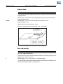
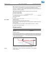
Print direction
AP 4.4
AP 5.4
AP 7.t
Printer
Printout
A
B
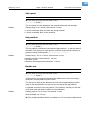
[10] Orientation of the printout „Foot first“ (A) or „Head first“ (B).
Foot first
(Default) Orientation of the printout according to [10A].
Head first
Orientation of the printout according to [10B]. Mind the following:
¯ Define the „true“ label length (without gap length) in parameter
PRINT PARAMETERS > Material length. If the label gap is wider than 5 mm, the
parameter SYSTEM PARAMETERS > Miss. label tol. must be set to a value more than
zero.
¯ The distance between material base line and the first printable dot is
1 mm. To keep this distance while printing „head first“, the material width
must be calculated as follows::
b Mat = ( b Bp – 1mm ) ⋅ 2 + b Lab , with
bMat: Material width
bBp: Backing paper width
bLab: Label width
35
09/09 Rev. 5.03-01
USER- / SERVICE MANUAL
Info-Printouts & Parameters
AP 4.4 – AP 5.4 – AP 7.t
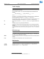
Punch offset
AP 4.4
AP 5.4
AP 7.t
The zero position can be determined offset in millimetre units from the detected gap position.
¯ The value is overwritten by the appropriate Easy Plug command when
sending label formats.
xxx mm
Setting range: -8 to +max. label length; Unit interval: 0,1mm
Default setting: 0 mm
Maximum offset in feed direction: -8 mm
Minimum offset against feed direction: +max. label length
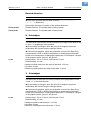
[11] Positive and negative offset in relation to the feed direction (arrow).
Bar code multip.
AP 4.4
AP 5.4
AP 7.t
Bar code height scaling factor
Increases the bar code height defined in the label layout (Easy-Plug) by multiplication by a factor of 1 to 10.
x
Setting range: 1 to 10; Unit interval: 1; Default setting: 1
The printed bar code height calculates starting with the value defined in the
label layout multiplied by the scaling factor x.
36
09/09 Rev. 5.03-01
USER- / SERVICE MANUAL
Info-Printouts & Parameters
AP 4.4 – AP 5.4 – AP 7.t
Tradit. Imaging
AP 4.4
AP 5.4
AP 7.t
¯ In production mode only.
Up to firmware version x.31, the barcode height was calculated with the
formula:
Barcodehight Print = ( Barcodehight Layout + 1 ) ⋅ x
with x = PRINT PARAMETERS > Barcode Multi.
By doing so, the printed barcode height in millimeters was by 1 higher than
the value defined in the layout (1 --> 2 mm, 2 --> 3 mm, etc.) 1).
From firmware version x.31 on, the printed barcode is exactly as high in millimeters, as the value in the layout is (1 --> 1 mm, 2 --> 2 mm, etc.) 1).
No
New height calculation (1 --> 1 mm, 2 --> 2 mm, etc.) is applied (default setting).
The plain copy line is printed with OCR-B font.
Yes
Setting for customers with print layouts based on the old height calculation
scheme.
The plain copy line of the barcodes EAN8, EAN13, UPC-A and UPC-E is printed with the same fonts, which older printer types like TTK or TTX x50 have
used.
UPC plain-copy
AP 4.4
AP 5.4
AP 7.t
The position of the first and last digit in the plain-copy line - underneath the
bar code - can be adjusted as required.
Raised
First and last digit of the UPCA or first digit with the UPCE are raised (default
setting).
In line
All digits in the decoded line are in line under the code.
EAN Readline
AP 4.4
AP 5.4
AP 7.t
<> Signs
Readline enclosed in "<>" signs or terminated by a ">"-Sign (EAN 13).
Standard
Readline without "<>" or ">" signs (default).
1) Assumed that PRINT PARAMETERS > Barcode Multi. = „1“.
37
09/09 Rev. 5.03-01
USER- / SERVICE MANUAL
Info-Printouts & Parameters
AP 4.4 – AP 5.4 – AP 7.t
EAN sep. lines
AP 4.4
AP 5.4
AP 7.t
EAN separation lines. Parameter for controlling of EAN or UPC barcodes if
they are printed without readline.
With readl. only
(Default) The seperation bars at the beginning, end and in the middle of the
barcode are only long, if the barcode is printed with a readline.
Always long
The seperation bars at the beginning, end and in the middle of the barcode
are always long, regardless if the barcode is printed with or without readline.
The position of the barcode is the same as with the readline option switched
on.
Rotated Barcodes
AP 4.4
AP 5.4
AP 7.t
Improves the readability of rotated (90° and 270°) bar codes.
Normal
„Normal“ printing without a special processing of rotated bar codes.
Optimized
(Default setting) The line and gap widths of rotated bar codes are modified in
order to improve their readability.
38
09/09 Rev. 5.03-01
USER- / SERVICE MANUAL
Info-Printouts & Parameters
AP 4.4 – AP 5.4 – AP 7.t
Cut mode
AP 5.4
¯ Only with mounted and activated cutter (SYSTEM PARAMETERS >
Periph. device = „Cutter“).
This is where the procedure for the label output and cut is defined.
Real 1:1 mode
The whole surface of the label is printable. The label is pushed forward to the
cutter for cutting. After the cut, the beginning of the next label is drawn back
under the print head. This reduces the output volume (in relation to a certain
time).
Printhead
Cutter
Avery
1. Printing
Avery
2. Printing finished
3. Feeding
4. Cut and
feed back
Avery
ry
Ave
[12] Printing process (schematic) in „Real 1:1 Mode“.
39
09/09 Rev. 5.03-01
USER- / SERVICE MANUAL
Info-Printouts & Parameters
AP 4.4 – AP 5.4 – AP 7.t
Batch mode
The whole surface of the label is printable. Cutting takes place during printing. This can result in brief interruptions within the print zone of the following
label. The output volume is at its maximum level.
Requirements for the batch mode are:
y Ribbon economy is not active (parameter SYSTEM PARAMETERS >
Ribbon autoecon. = "Deactivated")
y Material length >18 mm (>14 mm on the TTX 350)
y Number of cuts for a print job - at least 2 or more
Printhead
Cutter
Avery
1. Printing
Avery
2. Stop printing +
cut
3. Continue
printing
ery
Avery
Avery
Avery
Av
[13] Printing process in Batch mode (schematic).
Normal 1:1 mode
In N1:1 mode, cutting takes place during printing. The zero-line of the printing
is shifted 18 mm in y-direction. This offset equals the distance cutter-printhead. Caused by this shifting, the first 18 mm of the label are not printable.
These measurement corresponds to the distance between print head and
cutter. The output volume is at its maximum level.
(The offset of the zero-line is caused historically and serves the compatibility
of older printer models).
Printhead
Cutter
Avery
1. Printing
2. Printing
End
3. Feeding
Avery
Avery
4. Cutting
ry
Ave
[14] Printing process in Normal 1:1 mode (schematic).
40
09/09 Rev. 5.03-01
USER- / SERVICE MANUAL
Info-Printouts & Parameters
AP 4.4 – AP 5.4 – AP 7.t
Cut speed
AP 5.4
AP 7.t
¯ Only with mounted and activated cutter (SYSTEM PARAMETERS >
Periph. device = „Cutter“).
The cut speed is to be adjusted to the material thickness and strength.
x inch/s
Setting range: 2 to 5 inch/s; Unit interval: 1 inch/s
y 2 inch/s: extremely slow; for thick and strong material
y 5 inch/s: extremely fast; for thin material
Cut position
AP 5.4
AP 7.t
¯ Only with mounted and activated cutter (SYSTEM PARAMETERS >
Periph. device = „Cutter“).
The cut position is identical to the detected gap position, i. e. with the start of
the label. Fine settings to meet specific customer requirements can be programmed using the parameter PRINT PARAMETER > Cut position.
x inch/s
Setting range: -2.0 to +2.0 mm; Unit interval: 0.1mm
y Maximum offset in feed direction: -2.0 mm
y No offset: 0 mm
y Minimum offset against feed direction: -2.0 mm
Double cut
AP 5.4
AP 7.t
¯ Only with mounted and activated cutter (SYSTEM PARAMETERS >
Periph. device = „Cutter“).
Joining grids or the gap area between the labels can be removed using a
double cut, thereby improving the outline.
The first cut is offset by the distance set from the recognized gap position
away in the feed direction, the second cut is made at the gap position.
A possible correction of the cut position ("Cut position" function) is calculated for both cuts and must be taken into consideration.
x inch/s
Setting range: 0.0 to 5.0 mm; Unit interval: 0.1mm
Normal simple cut: 0.0 mm
¯ The smallest possible double cut distance of 1.0 mm must be adhered to!
41
09/09 Rev. 5.03-01
USER- / SERVICE MANUAL
Info-Printouts & Parameters
AP 4.4 – AP 5.4 – AP 7.t
Rewind direction
AP 5.4
¯ Only with mounted and activated rewinder (SYSTEM PARAMETERS >
Periph. device = „Rewinder“).
Determines the sense of rotation of the optional Rewinder.
Printing outside
Rewind direction: The printed label is facing outside.
Printing inside
Rewind direction: The printed label is facing inside.
X - Printadjust
AP 4.4
AP 5.4
AP 7.t
The zero point of the mask is moved in relation to the edge of the label on the
X- axis, i. e. lengthways to the material.
¯ If the setting is changed, while the print job is stopped, the printer
recalculates the format using the changed values.
¯ Caution with graphics, which are generated via one of the Easy Plug
commands #YI, #YIR or #YIB! If the graphics is shifted beyond the label
border as a consequence of changing the parameter "X-Printadjust", the part
of the graphics which "juts out" will get lost.
x.x mm
Setting range: -5.0 to +5.0 mm; Unit interval: 0.1mm
Default setting: 0.0 mm
y Maximum offset away from the edge of the label: +5.0 mm
y No offset: 0.0mm
y Maximum offset towards the edge of the label: -5.0 mm
Y – Printadjust
AP 4.4
AP 5.4
AP 7.t
The zero point of the mask is moved in relation to the gap position on the
Y-axis, i. e. in the feed direction.
¯ If the setting is changed, while the print job is stopped, the printer
recalculates the format using the changed values.
¯ Caution with graphics, which are generated via one of the Easy Plug
commands #YI, #YIR or #YIB! If the graphics is shifted beyond the label
border as a consequence of changing the parameter "Y-Printadjust", the part
of the graphics which "juts out" will get lost.
x.x mm
Setting range: -5.0 to +5.0 mm; Unit interval: 0.1mm
Default setting: 0.0 mm
y Maximum offset in feed direction: +5.0 mm
y No offset: 0.0mm
y Minimum offset against feed direction: -5.0 mm
42
09/09 Rev. 5.03-01
USER- / SERVICE MANUAL
Info-Printouts & Parameters
AP 4.4 – AP 5.4 – AP 7.t
Punch mode
AP 4.4
Automatic
AP 5.4
AP 7.t
Automatic mode, for material with a contrast zone = gap in the label.
"Automatic" is the default setting, suitable for all materials with which there is
a difference in the transparency between the label and gap of more than 2
values (see Description, sensor check).
Manual
Manual setting, for material with several varying contrast zones. Settings are
made using the parameter PRINT PARAMETER > Punch level.
The range of the value automatically measured by the gap detection can be
defined specifically for the label material. This allows materials with high-contrast proof points within the label to be processed, which would otherwise be
measured as 'false' gaps by the system. The corresponding setting value is
then equal to, or smaller than, the value measured at the actual gap.
Punch level
AP 4.4
AP 5.4
AP 7.t
¯ Only if PRINT PARAMETERS > Punch mode = „Manual“.
xxx
Setting range: 0 to 255; Unit interval: 1
The value xxx stands for the current contrast within the photoelectric switch
of the material which has just been inserted. This serves to determine a
threshold value for the inserted material.
Punchlevel
Punch xxx Val yyy
xxx = current measurement at the punch sensor
yyy = set threshold value
Example
Self-adhesive material with black bars lengthways across the label
y Reading:
– Masking paper: 30
– Masking paper + label: 60
– Masking paper + label + black bars: 190
y Setting value: 60
A setting value of 60 means that all readings over 60 are ignored, therefore
also the reading 190 at the black bar.
43
09/09 Rev. 5.03-01
USER- / SERVICE MANUAL
Info-Printouts & Parameters
AP 4.4 – AP 5.4 – AP 7.t
INTERFACE PARA
Interface parameter
> EASYPLUGINTERPR
Interface
AP 4.4
AP 5.4
AP 7.t
Interface type
This parameter sets the interface, by which the printer will receive data.
Serial Com1
Serial interface Com1.
P Selection of the type of serial interface is done with parameter INTERF. PARAM >
EASYPLUGINTERPR > Serial Port Mode.
Serial Com2
Serial interface Com2.
¯ Only with optional I/O board mounted.
¯ Mounting the I/O board changes the parameter SERVICE FUNCTION >
Easy Plug Monitor: The monitor data will be transmitted via Com1.
Centronics
Parallel interface (Centronics); Default setting
Only for Ethernet interface (10/100 Base T):
TCP/IP Socket
Print data can be sent to the printer via a TCP/IP socket
LPD Server
Print data can be sent to the printer via the LPR/LPD-protocol
USB
(AP 5.4, AP 7.t only) USB 1.1 interface
Automatic
All interfaces are enabled to receive data, but not simultaneously.
¯ Don´t send data to more than one interface at a time.
¯ Except are interfaces, which are being used by an option (e.g. OLV).
Spooler mode
AP 4.4
AP 5.4
AP 7.t
The operating mode of the spooler determines whether print series are processed individually, or whether the spooler can receive print data when printing several series.
Single print job
Single print series mode (the interface can only receive data after printing the
required number of labels of a single series)
Mult. print jobs
Multiple print series mode (the interface can receive data while the series is
being printed)
44
09/09 Rev. 5.03-01
USER- / SERVICE MANUAL
Info-Printouts & Parameters
AP 4.4 – AP 5.4 – AP 7.t
Printer ID No.
AP 4.4
AP 5.4
AP 7.t
Printer identification number
Determines the identification number of the printer. In such a way, the printer
can be addressed by the Easy Plug command #!An (n=printer ID).
The use of ID numbers is in particular reasonable for data transfer by RS422/
485 interface, if several printers are connected by one data line. Each of the
connected printers then only incorporates the data mapped to him by #!An
command.
xx
Setting range: 0 to 31; Unit interval: 1
Spooler size
AP 4.4
AP 5.4
AP 7.t
The memory capacity of the printer buffer can be set according to the requirements of each customer.
xxx Kbyte
Setting ranges:
– 64-xx Gen. 3: 16 to 2048 KBytes
– Other devices: 16 to 256 KBytes
Unit interval: 16 KBytes; default setting: 64 kBytes
¯
CAUTION! - All data present in the printer buffer is deleted when altering
the spooler size!
The maximum print format is influenced by the spooler size if no plug-in card
is used for memory expansion.
Offline mode
AP 4.4
AP 5.4
AP 7.t
Interf. disabled
Easy-Plug commands are not accepted, while the machine is in offline mode
(default setting).
Interf. enabled
Easy-Plug commands are accepted in offline mode.
Interface delay
AP 4.4
AP 5.4
AP 7.t
After switching from online to offline mode, the printer interface is deactivated. This parameter offers a setable delay time before deactivating the interface.
xxxx ms
Setting range: 0-1000; Unit interval: 100; Default setting: 0
45
09/09 Rev. 5.03-01
USER- / SERVICE MANUAL
Info-Printouts & Parameters
AP 4.4 – AP 5.4 – AP 7.t
> COM1 PORT
Baud rate
AP 4.4
AP 5.4
AP 7.t
Data transfer speed
Speed of data transfer using the serial interface.
xxxxxx Baud
Setting range: 300 to 115200 Baud; Unit interval: 300/600/1200/2400/4800/
9600/19200/38400/115200 (default)
No. of data bits
AP 4.4
AP 5.4
AP 7.t
This parameter can be defined in connection with both the serial and the parallel interface.
7
7 Data bits
8
8 Data bits
Parity
AP 4.4
AP 5.4
AP 7.t
Defines the parity check of serial transmitted data.
The parity bit is for checking data transmission. If the check shows an error,
a corresponding message is displayed. The setting must be identical at the
sender and the receiver. Normally transmission is set without a parity bit.
Odd
Odd parity.
A parity bit is added so that there is an odd number of 1 Bits.
Even
Even parity.
A parity bit is added so that there is an even number of 1 Bits.
None
No check bit. Sending and receiving without check bit.
Always zero
Check bit is always 0 (zero). Sending and receiving without parity check.
Stop bits
AP 4.4
AP 5.4
AP 7.t
Number of stop bits
Number of stop bits at the serial interface.
1 Bit
1 stop bit
2 Bit
2 stop bits
46
09/09 Rev. 5.03-01
USER- / SERVICE MANUAL
Info-Printouts & Parameters
AP 4.4 – AP 5.4 – AP 7.t
Data synch.
AP 4.4
AP 5.4
AP 7.t
Data synchronisation at the serial interface.
RTS/CTS
Data synchronisation through hardware
XON/XOFF
Data synchronisation through software
None
Handshake signals are ignored
Frame error
AP 4.4
AP 5.4
AP 7.t
Display
(Default) An error message is displayed, if a framing error is detected while
the printer is receiving serial data.
Ignore
Framing errors will be ignored, no error messages are displayed.
> COM2 PORT
¯ This menu only appears, if the optional I/O board is installed.
Baud rate
AP 4.4
AP 5.4
AP 7.t
¯ With mounted and connected I/O board only.
P See parameter Baud rate
on page 45.
No. of data bits
AP 4.4
AP 5.4
AP 7.t
¯ With mounted and connected I/O board only.
P See parameter No. of data bits
on page 45.
Parity
AP 4.4
AP 5.4
AP 7.t
¯ With mounted and connected I/O board only.
P See parameter Parity
on page 45.
47
09/09 Rev. 5.03-01
USER- / SERVICE MANUAL
Info-Printouts & Parameters
AP 4.4 – AP 5.4 – AP 7.t
Stop bits
AP 4.4
AP 5.4
AP 7.t
¯ With mounted and connected I/O board only.
P See parameter Stop bits
on page 45.
Data synch.
AP 4.4
AP 5.4
AP 7.t
¯ With mounted and connected I/O board only.
P See parameter Data synch.
on page 46.
Serial Port Mode
AP 4.4
AP 5.4
AP 7.t
¯ With mounted and connected I/O board only.
Setting of the serial interface type.
RS232
Sets Com2 to RS 232.
Data synchronisation may be done by hardware (RTS/CTS) or by software
(XON/XOFF). Maximum cable length is 15 m.
RS422
Sets Com2 to RS 422.
RS 422 is a 4 wire point to point connection, suitable for only one device.
Receiver and driver of the printer are always enabled. Data synchronization
is only possible by software (XON/XOFF). Maximum cable length is 1 km with
twisted telecommunication cable.
RS485
Sets Com2 to RS 485.
RS 485 is a 2 or 4 wire bus system for up to 30 devices. The printer´s receiver
is always enabled, the printer´s driver is only enabled, if the printer sends
data to the host. Data synchronization is only possible by software (XON/
XOFF). Maximum cable length is 1 km with twisted telecommunication cable.
Frame error
AP 4.4
AP 5.4
AP 7.t
¯ With mounted and connected I/O board only.
P See parameter Frame error
on page 46.
48
09/09 Rev. 5.03-01
USER- / SERVICE MANUAL
Info-Printouts & Parameters
AP 4.4 – AP 5.4 – AP 7.t
> COM3 PORT
Baud rate
P See parameter Baud rate
AP 4.4
AP 5.4
AP 7.t
AP 4.4
AP 5.4
AP 7.t
AP 4.4
AP 5.4
AP 7.t
AP 4.4
AP 5.4
AP 7.t
AP 4.4
AP 5.4
AP 7.t
AP 4.4
AP 5.4
AP 7.t
on page 45.
No. of data bits
Fixed setting: 8 Bits.
Parity
P See parameter Parity
on page 45.
Stop bits
Fixed setting: 2 Stop bits.
Data synch.
P See parameter Data synch.
on page 46.
Frame error
P See parameter Frame error
on page 46.
49
09/09 Rev. 5.03-01
USER- / SERVICE MANUAL
Info-Printouts & Parameters
AP 4.4 – AP 5.4 – AP 7.t
> CENTRONICS
PnP function
AP 4.4
AP 5.4
AP 7.t
Off
The printer doesn´t send any identification signals to the Centronics port.
On
The printer sends identification signals via the Centronics port (if any is
connected) to the host computers Windows operating system. Windows will
search for an appropriate driver. (Default setting).
> NETWORK PARAM.
IP addressassign
AP 5.4
AP 7.t
¯ A change of this parameter setting forces a printer restart.
Fixed IP address
This setting activates the parameters "Net mask" and "Gateway address"
(see below).
DHCP
IP address is assigned automatically. The assigned IP address is displayed
for a moment on the printer display, while the printer is starting.
IP address
AP 5.4
xxx.xxx.xxx.xxx
AP 7.t
Setting range per xxx value: 0 to 255
Change between the digits by pressing the Cut or Feed button; Acknowledge
the setting by pressing the Online button. After a change of the IP address,
the printer will reset automatically.
Net mask
AP 5.4
xxx.xxx.xxx.xxx
AP 7.t
Setting range per xxx value: 0 to 255
Depending on the set IP address appears a default value.
¯ We recommend to use the default value!
50
09/09 Rev. 5.03-01
USER- / SERVICE MANUAL
Info-Printouts & Parameters
AP 4.4 – AP 5.4 – AP 7.t
Gateway address
AP 5.4
xxx.xxx.xxx.xxx
AP 7.t
Setting range per xxx value: 0 to 255
000.000.000.000 = no gateway is used
Port address
AP 5.4
AP 7.t
Setting range: 1024 to 65535. Default: 9100.
Ethernet speed
AP 5.4
AP 7.t
Auto negotioation
The communication speed is selected automatically.
10M half duplex
The communication speed is set to 10 MBit/s half duplex.
10M full duplex
The communication speed is set to 10 MBit/s full duplex.
100M half duplex
The communication speed is set to 100 MBit/s half duplex.
100M full duplex
The communication speed is set to 100 MBit/s full duplex.
MAC address
AP 5.4
AP 7.t
Displays the MAC address of the CPU board. This address can not be
changed in the parameter menu.
SNMP agent
AP 5.4
AP 7.t
¯ Function is not released yet.
SNMP password
AP 5.4
AP 7.t
¯ Only in production mode.
¯ Function is not released yet.
51
09/09 Rev. 5.03-01
USER- / SERVICE MANUAL
Info-Printouts & Parameters
AP 4.4 – AP 5.4 – AP 7.t
FTP server
AP 5.4
AP 7.t
The File Transfer Protocol (FTP) server (RFC959) allows access to the RAM
disk inside of the printer and, if available, to the CompactFlash-card. The FTP
server is capable of multisession mode, without evaluating the user name
when logging in. The password must match the set password (see below).
The FTP server can be used with the following clients:
y GNU Midnight Commander 4.6.0 (OS: Linux)
y WS-FTP Pro 5.0 (OS: Windows NT/95)
y MS-IE 5.0, 5.5, 6.0 (OS: Windows NT/95)
Folder structure
Comment
CF
This folder is only visible with a CF-card inserted.
FONTS
Folder for font files on CF-card
FORMATS
Folder for print job files on CF-card
GRAPHICS
Folder for graphic files on CF-card
LOGOS
Folder for logo files on CF-card
FONTS
Folder for font files on the internal RAM disk
GRAPHICS
Folder for graphic files on the internal RAM disk
LOGOS
Folder for logo files on the internal RAM disk
[4]
This folder structure is visible in the FTP client window, if a CF-card is inserted into the
printer card slot.
Enabled
Switches the FTP server on.
Disabled
Switches the FTP server off.
FTP password
AP 5.4
AP 7.t
Input of the FTP server password by means of a connected keyboard or the
printers operation panel. Default setting: „avery“.
Changing the password:
1. Press the Esc button. The cursor jumps to the first character.
2. Press the Cut- or Feed button until the wanted character appears.
Acknowledge by pressing the Online button.
3. Put in the next character.
4. Acknowledge the new password by pressing the Online button.
¯ If a keyboard is connected, this can be used for typing in the password.
52
09/09 Rev. 5.03-01
USER- / SERVICE MANUAL
Info-Printouts & Parameters
AP 4.4 – AP 5.4 – AP 7.t
WEB server
AP 5.4
AP 7.t
The web server may be used to
y read out or change parameter settings of the printer into a web browser
y Operate the printer via a web browser.
Requirements for use of the web server function:
y Printer is connected to network
y A valid IP address is assigned to the printer (by the network administrator or
by a DHCP server)
y INTERFACE PARA > NETWORK PARAM. > WEB server must be set to „Enabled“.
Starting the web server:
1. Write down the printers IP address (INTERFACE PARA > NETWORK PARAM. >
IP address).
2. Start the web browser.
Insert into the address field:
http://[IP address without leading zeros]
Example: IP address = 144.093.029.031
Input: http://144.93.29.31
3. Click „Login“.
4. Type in user name (admin) and password (admin).
If the login was successful, you will find the following menu items at the left
window margin:
Menu item
Function
Home
Jump to the home page
Logout
Interrupt the connection to the printer
Parameter
Opens the parameter menu. By clicking on submenus and parameters, those can be opened and the parameter setttings be
changed.
¯ Some parameters force the printer to reset, if their
setting is modified by means of the operation panel. If the
parameters are changed via the web server, this doesn´t
happen automatically. Therefore, the modifications only
become effective after the next printer restart. A restart
can be triggered remote in the „Display view“.
Display view
Opens the display operation panel. Enables remote operation
of the printer.
Download
Opens another browser window with the URL of the FTP server. For more information read the description of
INTERFACE PARA > NETWORK PARAM. > FTP server.
Help
Help texts
[5]
Functions of the web server.
Enabled
Switches the web server on.
Disabled
Switches the web server off.
53
09/09 Rev. 5.03-01
USER- / SERVICE MANUAL
Info-Printouts & Parameters
AP 4.4 – AP 5.4 – AP 7.t
WEB display refr
WEB display refresh
AP 5.4
AP 7.t
Automatic updating of the web browser display. The setting determines the
time in seconds between two updates.
¯ Setting 0 = „no automatic updating“.
xx s
Setting range: 0 to 20; Default setting: 5
WEB admin passw.
WEB administrator password
AP 5.4
AP 7.t
¯ Only in production mode.
Modifying the password for web server access as admin.
Default setting: „admin“
¯ The user name is also „admin“.
¯ If the user logs in as admin to the web server, he/she has access to all
parameters, which are not marked with the footmark „only in production
mode“.
Changing the password at the operating panel:
1. Press the Esc button. The cursor jumps to the first character.
2. Press the Cut- or Feed button until the wanted character appears.
Acknowledge by pressing the Online button.
3. Type in the next character.
4. Acknowledge the new password by pressing the Online button.
¯ Alternatively, the password can be typed in using a keyboard, or via the
web server.
WEB supervisor p.
WEB supervisor password
AP 5.4
AP 7.t
¯ Only in production mode.
Modifying the password for web server access as supervisor.
Default setting: „supervisor“
¯ The user name is also „supervisor“.
¯ If the user logs in as supervisor to the web server, he/she has access to
all parameters.
Changing the password at the operating panel:
54
09/09 Rev. 5.03-01
USER- / SERVICE MANUAL
Info-Printouts & Parameters
AP 4.4 – AP 5.4 – AP 7.t
1. Press the Esc button. The cursor jumps to the first character.
2. Press the Cut- or Feed button until the wanted character appears.
Acknowledge by pressing the Online button.
3. Type in the next character.
4. Acknowledge the new password by pressing the Online button.
¯ Alternatively, the password can be typed in using a keyboard, or via the
web server.
Time client
AP 5.4
AP 7.t
Loads the current time from a time server.
Disabled
The time client is switched off.
Enabled
The time client is switched on. The time is loaded with the frequency set under Sync. interval from a time server with the IP address Time server IP.
With the time client service, the current date and time can be obtained
from a time server using RFC868 time protocol on UDP port 37. For
this purpose, a time server IP address needs to be given. Date and
time are initially requested at start up an optional in a setable update interval
during operation time. It is also stored in the internal real time clock. There is
no time offset or daylight saving hour, so the server time must exactly match
the local time of the printer.
Time server IP
AP 5.4
AP 7.t
IP address of the time server.
¯ Only appears if INTERFACE PARA > NETWORK PARAM. > Time client =
„Enabled“.
xxx.xxx.xxx.xxx
Enter the IP address following the xxx.xxx.xxx.xxx schema.
Setting range for each xxx value: [0…255].
Sync. Interval
AP 5.4
AP 7.t
Determines the frequency for time requests.
¯ Only appears if INTERFACE PARA > NETWORK PARAM. > Time client =
„Enabled“.
xxxx
Setting range: [0…9999] s; Default setting: 3600 s.
55
09/09 Rev. 5.03-01
USER- / SERVICE MANUAL
Info-Printouts & Parameters
AP 4.4 – AP 5.4 – AP 7.t
DHCP host name
AP 5.4
AP 7.t
Host name of the printer. Default setting: „Device name“ + the last 3 figures
of the MAC adress.
Typing in the host name at the operating panel:
1. Press the Esc button. The cursor jumps to the first character.
2. Press the Cut- or Feed button until the wanted character appears.
Acknowledge by pressing the Online button.
¯ Valid characters: A-Z, a-z, 0-9, 3. Type in the next character.
4. Acknowledge the new password by pressing the Online button.
¯ Alternatively, the password can be typed in using a keyboard, or via the
web server.
WLAN SSID
AP 5.4
AP 7.t
¯ Only with plugged-in WLAN CF-card
A Service Set Identifier (SSID) is the identification of a radio frequency network, which is based on IEEE 802.11.
Each WLAN owns a configurable SSID, by which the network is identified.
The SSID is the name of the network.
The SSID character string is configured in the base station (Access Point) of
the WLAN. It must be also configured on all clients, which are supposed to
access the access point. The SSID is attached uncoded to all pakkets to
identify them as part of that network.
xxxxxxxxxxx…
The SSID consists of a maximum of 32 alphanumeric characters. Default setting: „avery“
P Detailed information about using the WLAN feature: read the user manual,
topic section Advanced Applications .
WLAN WEP
AP 5.4
AP 7.t
¯ Only with plugged-in WLAN CF-card
WEP („Wired Equivalent Privacy“) is an encryption scheme for WLAN.
Disabled
(Default setting) Communication with the host is not encoded.
64Bit key
Communication with the host is encoded using 64 Bit WEP encoding.
128Bit key
Communication with the host is encoded using 128 Bit WEP encoding.
56
09/09 Rev. 5.03-01
USER- / SERVICE MANUAL
Info-Printouts & Parameters
AP 4.4 – AP 5.4 – AP 7.t
P Detailed information about using the WLAN feature: read the user manual,
topic section Advanced Applications .
WLAN default key
AP 5.4
AP 7.t
¯ Only with plugged-in WLAN CF-card
Selection of the encryption key, which is used for packet transmission.
x
Setting range: 1-4; Default setting: 1
P Detailed information about using the WLAN feature: read the user manual,
topic section Advanced Applications .
WLAN 64Bit key 1
AP 5.4
AP 7.t
¯ Only with plugged-in WLAN CF-card
Definition of an encryptioin key for pakket transmission. The key will be used,
if it is enabled under INTERFACE PARA > NETWORK PARAM. > WLAN default key.
xxxxxxxxxxx…
Character string of 26 hexadecimal characters. Default setting:
„123456789abcd123456789abcd“
¯ Admissible characters: A-Z, a-z, 0-9
P Detailed information about using the WLAN feature: read the user manual,
topic section Advanced Applications .
WLAN 64Bit key 2
AP 5.4
AP 7.t
¯ Only with plugged-in WLAN CF-card
P See parameter WLAN 64Bit key 1
on page 56.
WLAN 64Bit key 3
AP 5.4
AP 7.t
¯ Only with plugged-in WLAN CF-card
P See parameter WLAN 64Bit key 1
on page 56.
WLAN 64Bit key 4
AP 5.4
AP 7.t
¯ Only with plugged-in WLAN CF-card
P See parameter WLAN 64Bit key 1
on page 56.
57
09/09 Rev. 5.03-01
USER- / SERVICE MANUAL
Info-Printouts & Parameters
AP 4.4 – AP 5.4 – AP 7.t
WLAN 128Bit key 1
AP 5.4
AP 7.t
¯ Only with plugged-in WLAN CF-card
Definition of an encryptioin key for pakket transmission. The key will be used,
if it is enabled under INTERFACE PARA > NETWORK PARAM. > WLAN default key.
xxxxxxxxxxx…
Character string of 26 hexadecimal characters. Default setting:
„123456789abcd123456789abcd“
¯ Admissible characters: A-Z, a-z, 0-9
P Detailed information about using the WLAN feature: read the user manual,
topic section Advanced Applications .
WLAN 128Bit key 2
AP 5.4
AP 7.t
¯ Only with plugged-in WLAN CF-card
P See parameter WLAN 128Bit key 1
on page 57.
WLAN 128Bit key 3
AP 5.4
AP 7.t
¯ Only with plugged-in WLAN CF-card
P See parameter WLAN 128Bit key 1
on page 57.
WLAN 128Bit key 4
AP 5.4
AP 7.t
¯ Only with plugged-in WLAN CF-card
P See parameter WLAN 128Bit key 1
on page 57.
WLAN com quality
AP 5.4
AP 7.t
¯ Only with plugged-in WLAN CF-card
This value represents the signal-to-noise ratio (SNR) of the connection. The
value is shown in % and is a measure for the connection quality.
x%
WLAN communication quality in %
P Detailed information about using the WLAN feature: read the user manual,
topic section Advanced Applications .
58
09/09 Rev. 5.03-01
USER- / SERVICE MANUAL
Info-Printouts & Parameters
AP 4.4 – AP 5.4 – AP 7.t
WLAN signal lev.
AP 5.4
AP 7.t
¯ Only with plugged-in WLAN CF-card
Shows the WLAN average signal level in percent. This value suits for optimizing the location of the printer or access point to get the best network connection.
x%
Signal level in %
P Detailed information about using the WLAN feature: read the user manual,
topic section Advanced Applications .
> OPTIONS
Remote Display
AP 4.4
AP 5.4
AP 7.t
Parameter only for development use. Enables controlling the operation panel
via serial interface, e.g. with a PC.
¯ This parameter has nothing to do with the optional available remote
display, which is connected to a separate outlet.
P For details about installing the remote display option, see service manual of
the printer, topic section „Service Mechanics“, chapter „Assembling accessories“.
Disabled
Remote display is not activated.
Serial Com1
The Remote display is connected to Com1.
¯ This setting option is only visible, if no other option is activated at Com1.
Serial Com2
The Remote display is connected to Com2.
¯ This setting option is only visible, if no other option is activated at Com2.
59
09/09 Rev. 5.03-01
USER- / SERVICE MANUAL
Info-Printouts & Parameters
AP 4.4 – AP 5.4 – AP 7.t
RFID Option
AP 5.4
Disabled
RFID-Option is not activated (RFID = Radio Frequency Identification).
¯ The RFID reader is connected to Com1 or Com2 internally, what means,
that it does not have to be plugged into the external serial interface
connector.
Serial Com1
Serial Com3
The RFID reader is connected to Com1.
¯ This setting option is only visible, if no other option is activated at Com1.
The RFID reader is connected to Com3.
¯ This setting option is only visible, if no other option is activated at Com3.
StandAlone Input
AP 4.4
AP 5.4
AP 7.t
Defines an interface for data input in standalone mode.
¯ Interfaces are only selectable, if installed and not used by another
function (e. g. as data interface). If INTERFACE PARA > EASYPLUGINTERPR >
Interface = „Automatic“, all interfaces besides Com3 are blanked out.
None
No data input via interface.
Serial Com1
Com1 is applied for data input in standalone mode.
Serial Com2
Com2 is applied for data input in standalone mode.
Serial Com3
Com3 is applied for data input in standalone mode.
TCP/IP socket
TCP/IP socket is applied for data input in standalone mode.
60
09/09 Rev. 5.03-01
USER- / SERVICE MANUAL
Info-Printouts & Parameters
AP 4.4 – AP 5.4 – AP 7.t
SYSTEM PARAMETERS
Foil end warning
AP 4.4
AP 5.4
AP 7.t
Setting of a limit diameter for the ribbon roll. If the ribbon roll diameter falls
below the set value, the displayed message changes from…
ONLINE
X JOBS
…to…
FOLIE
X JOBS
…while the display is blinking.
64-xx, DPM / PEM, ALX 92x:
Additionally to the display message, a signal is set at the (optional) USI.
P For details refer to the parameters DP INTERFACE > Ribbon signal and
SERVICE DATA > OPERATION DATA > Foil diameter
x.xx mm
Setting range: 25.4 to 50.0 mm; Unit interval: 0.1 mm;
Default setting: 25.4 mm
Foil warn stop
AP 4.4
AP 5.4
AP 7.t
Disabled
(Default setting) Printer does not stop in case of a „Foil end warning“.
Enabled
If a „Foil end warning“ occurs, the printer stops after the current label and
shows the status message:
PrintStatus:
Foil low
5110
« Press the online button to acknowledge the message, then the feed button to
continue printing.
61
09/09 Rev. 5.03-01
USER- / SERVICE MANUAL
Info-Printouts & Parameters
AP 4.4 – AP 5.4 – AP 7.t
Print Interpret.
AP 4.4
AP 5.4
AP 7.t
The printer uses the MONARCH LANGUAGE INTERPRETER™ to interprete and process data.
Easyplug
Printjobs written in the Easy-Plug command language can be interpreted.
Lineprinter
Lineprinter (or similar to Lineprinter), print-out of the print command.
Hex Dump
Print-out in hexadecimal format.
In Lineprinter and Hex Dump, commands are printed out in the form of a list
with the character set 12.
¯ When setting Lineprinter or Hex Dump, Easy Plug commands which have
not yet been processed are deleted!
MLI
Printjobs written in the ZPL II® 1) command language can be interpreted.
¯ Firmware loading requires changing into EasyPlug first.
EasyPlug / MLI
Printjobs in EasyPlug and MLI can be interpreted.
¯ Use this setting only for simple printjobs. Complications are more likely
with this setting.
1) ZPL II is a registered trademark of ZIH Corp. ZIH Corp. and Avery Dennison (including Paxar
Corporation and its subsidiaries) are not related in any way, and ZIH Corp. has not licensed or
otherwise sponsored MONARCH® printers or Avery Dennison's MONARCH LANGUAGE
INTERPRETER™. MONARCH®, MONARCH LANGUAGE INTERPRETER, MLI are trademarks
of Paxar Americas, Inc. Avery Dennison is a registered trademark of Avery Dennison
Corporation.
62
09/09 Rev. 5.03-01
USER- / SERVICE MANUAL
Info-Printouts & Parameters
AP 4.4 – AP 5.4 – AP 7.t
Character sets
AP 4.4
AP 5.4
AP 7.t
Setting the character set:
y 8bit: Choose between IBM and ANSI character set.
y 7Bit: Additionally to the IBM and ANSI character sets, some country specific
character sets are provided, which have some characters allocated
differently (see table below)
¯ The country specific character sets are only suitable for older 7bit
applications!
Decimal
35
36
64
91
92
93
94
96
ASCII
#
$
@
[
\
]
^
‘
{
|
}
~
ISO 8859-2 a)
#
$
@
[
\
]
^
`
{
|
}
~
print
ANSI (CP 1250) a)
#
$
@
[
\
]
^
`
{
|
}
~
print
ANSI (CP 1252)
#
$
@
[
\
]
^
`
{
|
}
~
print
IBM
#
$
@
[
\
]
^
`
{
|
}
~
print
Special
ƒ
¢
¼
½
«
•
»
±
blank
Norway
#
$
@
Æ
¥
Å
^
`
æ
¢
å
~
blank
Spain
#
$
@
i
Ñ
Ç
^
`
¿
ñ
ç
~
blank
Sweden
#
•
É
Ä
Ö
Å
Ü
é
ä
ö
å
ü
blank
Italy
Š
$
§
°
ç
é
^
ù
à
ò
è
`
blank
Germany
#
$
§
Ä
Ö
Ü
^
`
ä
ö
ü
ß
blank
France
£
$
à
°
ç
§
^
`
é
ù
è
~
blank
United Kingdom
£
$
@
[
\
]
^
`
{
|
}
½
blank
USA
#
$
@
[
\
]
^
`
{
|
}
~
blank
blank blank
blank blank
123 124 125 126 >127
blank = space, print = printable
[6]
Country settings for applications, which base on 7bit ASCII code.
a) Not available with AP 4.4
P For complete tables of all fixfonts characters available with setting "IBM" refer
to the User Manual, topic section "Internal Fonts". You also find there a
comparison of the IBM and ANSI character sets.
63
09/09 Rev. 5.03-01
USER- / SERVICE MANUAL
Info-Printouts & Parameters
AP 4.4 – AP 5.4 – AP 7.t
Character filter
AP 4.4
AP 5.4
AP 7.t
Character >= 20Hex
Filter function is activated. Characters smaller than 20H are filtered out of the
data flow.
All character
Filter function is deactivated. Characters smaller than 20H are treated as normal characters.
Light sens. type
AP 4.4
AP 5.4
AP 7.t
Light sensor type
The optional reflex photoelectric switch for labels with reflecting length markings, or the normal factory-fitted photoelectric switch for labels with transparent or register gaps (self-adhesive labels), must be defined according to the
application.
Short label opt.
(AP 5.4 only) Activates the optional short label sensor.
¯ Appears only in AP 5.4 printers which are equipped with the short label
sensor.
Full Size
Full Size photoelectric switch (Adjustment range is the material width).
Reflex
Reflex photoelectric switch (for reflecting markings)
Punched
Transparent photoelectric switch (for gaps)
Head-sensor dist.
AP 4.4
AP 5.4
AP 7.t
¯ Parameter appears only in production mode or if a value > 0 is set.
Printhead-sensor distance
Special function for setting non-standard punch sensors. Such sensors can
be applied in special application devices ("Nistan"). The value x is the distance between thermal edge and punch sensor in millimeters.
x mm
Setting range: 0 to 400 mm
¯ A „non standard sensor“ must be installed and connected instead of the
regular punch sensor.
¯ 0 = disabled (the regular punch sensor is used).
64
09/09 Rev. 5.03-01
USER- / SERVICE MANUAL
Info-Printouts & Parameters
AP 4.4 – AP 5.4 – AP 7.t
Sens. punch-LS
AP 4.4
AP 5.4
AP 7.t
Sensitivity punch light sensor
Sets the sensitivity of the material photoelectric switch.
xxx%
Setting range: 10 to 100%; Unit interval: 10%
Default setting: 50%
Maximum sensitivity: 100%. for narrow gaps (perforations).
Minimum sensitivity: 1%. for clearly detectable gaps.
¯ Too high a level of sensitivity can lead to gaps being detected which do
not even exist (on proofs, material thickness fluctuations, perforations etc.).
Ribbon autoecon.
AP 7.t
Ribbon automatic economy mode
The ribbon feed can be interrupted during print periods with the ribbon automatic economy parameter. This saves ribbon, particularly with long labels
with a minimum print area. The automatic function should only be activated
with unprinted areas from approx. 10 mm in length.
A selection can be made between thermal transfer printing and thermal direct
printing. It is necessary to select the type of printing in order to be able to
switch over the ribbon end detection.
Thermal printing
Thermal direct printing (Ribbon-end-LS switched off)
Activated
(not with AP 4.4/5.4)
Thermal transfer printing with ribbon automatic economy mode on.
Deactivated
Thermal transfer printing with ribbon automatic economy mode off.
65
09/09 Rev. 5.03-01
USER- / SERVICE MANUAL
Info-Printouts & Parameters
AP 4.4 – AP 5.4 – AP 7.t
Feed mode
AP 7.t
Head up
(Default) The printhead is lifted during label material initialization and label
feeding.
Head down
The printhead is down during label material initialization and label feeding.
Foil mode
AP4.4
Thermo transfer
Thermo transfer printing (Ribbon sensor activated)
Thermal printing
Thermo direct printing (Ribbon sensor deactivated)
AP 5.4
Turn-on mode
AP 4.4
AP 5.4
AP 7.t
Operating mode of the printer after it has been switched on.
Online
Printer starts in on-line mode.
Offline
Printer starts in off-line mode.
Standalone
Printer starts in standalone mode.
Error reprint
AP 4.4
AP 5.4
AP 7.t
If an error occurs while a label is printed, the last printed label will normally
be reprinted. In case of label layouts containing variable data like e.g. count
fields, switching off the reprint function possibly makes sense.
Enabled
Reprint in error cases (default setting)
Disabled
No reprint in error cases.
EasyPlug error
AP 4.4
AP 5.4
AP 7.t
Handling of errors caused by faulty Easy-Plug commands.
Tolerant handl.
The label is printed, after the Easy-Plug/Bitimage error was acknowledged
(default setting).
Strict handling
The Easy-Plug command, which caused the error, is displayed after approx.
2 seconds in the lower display line. The displayed text is up to 30 characters
long and is scrolled automatically.
If a single character caused the error, this character is marked with „>> <<„
in the display text, to facilitate the detection.
66
09/09 Rev. 5.03-01
USER- / SERVICE MANUAL
Info-Printouts & Parameters
AP 4.4 – AP 5.4 – AP 7.t
By pressing the cut button, the display can be toggled between error message and Easy-Plug command text.
After acknowledging the first occured Easy-Plug error, the printjob and the
spooler are deleted (as by #!CA). This prevents the printing of labels with format errors.
Single job mode
AP 4.4
AP 5.4
AP 7.t
In single job mode (also stop mode) the printer stops after every job and waits
until the operator restarts the print process.
Deactivated
Single job mode is switched off (default setting).
Activated
Single job mode is switched on. The printer always displays "Start next job",
before starting a new print job. This requests the user to acknowledge by
pressing the Online button.
Head resistance
AP 4.4
AP 5.4
AP 7.t
For optimum print quality, the individual print head resistance of the thermo
head employed in the device must be set once with this parameter.
When replacing the print head, the resistance value of the print head (to be
read off from the print head) must be entered again.
¯CAUTION! - Entering a false value can damage the print head!
« Read off the correct value from the print head and set it accordingly.
¯ The value set here remains when the factory settings are carried out.
xxxx Ohm
Setting range: 1000 to 1500 Ohm; Unit interval: 1 Ohm
Setting the print head resistance:
Setting:
1. From the print head, read off the resistance value to be set and make a note
of it (1000 to 1500).
2. In off-line mode press the Prog. button, display: PRINT INFO.
3. Press the Cut button until SYSTEM PARAMETER is displayed.
4. Press the Online button, display:
SYSTEM PARAMETER
Foil end warning
5. Press the Cut button until the following is displayed:
SYSTEM PARAMETER
Head resistance
67
09/09 Rev. 5.03-01
USER- / SERVICE MANUAL
Info-Printouts & Parameters
AP 4.4 – AP 5.4 – AP 7.t
6. Press the Online button, set value is displayed.
7. Set the previously noted resistance value of the print head using the Feed
and Cut buttons.
8. Press the Online button to confirm the set value.
9. Press the Prog. button to return to the display OFFLINE 0 JOBS.
Temp. reduction
AP 4.4
AP 5.4
AP 7.t
Reduction in the print head temperature
The parameter SYSTEM PARAMETER > Temperature reduct. allows the power supply
to be reduced in the event of an increase in the print head temperature, thereby ensuring an evenly good print image.
xxx%
Setting range: 0 to 100%; Unit interval: 5%
The following setting alternatives are available:
y 0%: No temperature reduction.
y xx%: Up to xx% temperature reduction with a hot print head.
y Default setting: 20%.
P For further information refer to the user manual, topic section „Advanced
Application“, chapter „Printing with Termperature Compensation“
Thin line emphas
AP 4.4
AP 5.4
¯ Only in production mode
Thin line emphasis. Print emphasis for thin lines in order to get a better print
result.
On
(Default) Print emphasis for thin lines is switched on.
Thin lines in the printout, which run crossways to the printing direction, are
printed approx. 1.5 times wider. This may have the effect, that small white
patches are closed with color (e.g. in the „e“ with very small fonts).
Off
Print emphasis for thin lines is switched off.
Voltage offset
AP 4.4
AP 5.4
AP 7.t
The voltage offset increases the head voltage and therefore the head temperature which e.g. was set by Easy Plug command (HV).
xx%
Setting range: 0 to 20%; Unit interval: 1%
Default setting: 0%
68
09/09 Rev. 5.03-01
USER- / SERVICE MANUAL
Info-Printouts & Parameters
AP 4.4 – AP 5.4 – AP 7.t
Miss. label tol.
AP 4.4
AP 5.4
AP 7.t
Missing label tolerance
The maximum search path for gaps which cannot be found can be varied. In
cases of difficult gap detection (i. e. minimum variation in the light transparency, gap to label), shortening the search path is to be recommended. Label
loss resulting from gaps not being detected can be reduced in this way. Printing does not take place during the search process.
xx
Setting range: 0 to 50; Unit interval: 1
y Example 0 (Zero label length): A gap must be found after a printed label
otherwise an error message is given. This setting is for detecting every
missing label.
y Example 5 (Five label lengths): A gap must be found after a maximum of 5
label lengths otherwise an error message is given.
Gap detect mode
AP 4.4
AP 5.4
AP 7.t
After one of the following events, the printer must always search for the
punch, that is initialize the label material:
y After switching the printer on
y After changing the label material
Manual
The operator has to initialize the material always manually by pressing the
feed key several times.
Autom. Forward
(Default for printers) The material initialization is always done automatically,
if necessary. There is no backward movement of the material during the initialization.
Autom. feed back
¯ Only 64-xx Dispenser, ALX 92x, DPM/PEM
(Default for those devices) The material initialization is always done automatically, if necessary. The label material is moved forward and backward during
the initialization. The stretch of backward movement can be set with parameter SYSTEM PARAMETER > Max InitFeedback (see below).
69
09/09 Rev. 5.03-01
USER- / SERVICE MANUAL
Info-Printouts & Parameters
AP 4.4 – AP 5.4 – AP 7.t
Periph. device
AP 4.4
AP 5.4
AP 7.t
After installation, options must be selected under "Peripheral device" in order
to be assured of the corresponding sensor queries and printer reactions.
¯ CAUTION! - Selecting an incorrect option can lead to malfunctions or
damage!
None
No peripheral device is installed.
Cutter
Sets the printer firmware to the cutter option. Selection permits access to the
cut parameters.
Rewinder
Sets the printer firmware to the rewinder option. Selection permits access to
the rewinder setting parameters.
Tear-off edge
Sets the printer firmware to the tear-off edge option. The punch is fed forward
to the tear-off edge.
Dispenser
Setting for AP 5.4 dispenser version.
Intern Rewinder
AP 5.4 only: Setting for printer operation in „internal rewinder“ mode, that is
operation with a deflector and without dispensing edge.
Tear-off + sensor
AP 5.4 only: Setting for using the dispensing edge as tear-off edge. The
punch is fed forward to the dispensing edge.
TCS
AP 7.t only: Textile Cutter-Stacker
Singlestartquant
AP 4.4
AP 5.4
AP 7.t
Single start quantity
xx
Setting range: 1 to 10; Unit interval: 1
External signal
AP 4.4
AP 5.4
AP 7.t
The parameter determines, if and how an incoming signal at the - optional single start connector will be interpreted.
Disabled
Signal interpretation disabled.
Singlestart
The signal triggers the printing of a single label. This setting may be used e.g.
for printing single labels by means of a foot switch.
Stacker full
The signal triggers the display of a status report and stops the printer. This
setting may be used when using a stacker (= stacker full signal).
P Detailed information about using start signals can be found in the user man-
ual, topic section „Advanced Applications“, chapter „Printing with start signal“, Settings in the parameter menu 70
09/09 Rev. 5.03-01
USER- / SERVICE MANUAL
Info-Printouts & Parameters
AP 4.4 – AP 5.4 – AP 7.t
Start mode
AP 4.4
AP 5.4
AP 7.t
Settings for interpreting the start signal.
¯ Only relevant for start signals coming from the following sources:
– Foot switch connector (SYSTEM PARAMETERS > Start source = „Foot switch“)
– D-Sub connector for dispensing edge light barrier (SYSTEM PARAMETERS >
Start source = „Light barrier“)
– not USI
P Detailed information about using start signals can be found in the user man-
ual, topic section „Advanced Applications“, chapter „Printing with start signal“, Settings in the parameter menu Level
Labels of a certain print job are being printed as long as the signal level is
"high". When using a foot switch, labels are printed as long as somebody
keeps his/her foot on the foot switch.
Edge
The rising / falling signal edge triggers the printing of exactly one label (Default setting).
P See parameter Signal edge
on page 71.
71
09/09 Rev. 5.03-01
USER- / SERVICE MANUAL
Info-Printouts & Parameters
AP 4.4 – AP 5.4 – AP 7.t
Signal edge
AP 5.4
AP 7.t
¯ AP 5.4/AP 7.t: This parameter does not appear, if an I/O board is installed.
This parameter determins either the falling or the rising edge of an incoming
signal as trigger.
Falling edge
The falling signal edge triggers a certain printer reaction.
Rising edge
The rising signal edge triggers a certain printer reaction.
Print contrast
AP 4.4
xxx%
AP 5.4
AP 7.t
Setting range: 1 to 120%; Unit interval: 1; Default setting: 60
CAUTION!
The parameter Print contrast affects directly the life durance of the printhead.
It counts: „The higher the setting of Print contrast is, the lower is the life durance of the printhead“. This counts even more for settings above 100%.
Therefore mind:
« Always choose the lowest possible setting necessary to produce an acceptable print result.
72
09/09 Rev. 5.03-01
USER- / SERVICE MANUAL
Info-Printouts & Parameters
AP 4.4 – AP 5.4 – AP 7.t
Ram disk size
AP 4.4
AP 5.4
AP 7.t
A part of the printer memory can be identified as a RAM disk. The RAM disk
can be used in the same way as the Compact Flash Card, e.g. for storage of
logos or fonts.
With the parameter Ram disk size, the customer can set the size of the RAM
disk to his needs. Be aware, that RAM disk memory is not available for print
picture buildup. Use of much RAM disk memory reduces the picture buildup
rate of the printer.
¯ Switching the printer off extinguishes the memory content! Fonts, logos
etc., which were loaded on the RAM disk, must be loaded again after
switching the printer off.
xxxx KBytes
Setting range: 2048 KBytes to the maximum size, which depends on the
memory configuration and allocation of the printer; Unit interval: 128 KBytes;
Default setting: 512 KBytes
Font downl. area
AP 4.4
AP 5.4
AP 7.t
If speedo-fonts are supposed to be used, they have first to be copied to a reserved RAM disk area. Use parameter „Font downl. area“ to reserve the RAM
disk area in the required size.
The size of the required RAM disk area depends on the size of the font files
to be loaded.
¯ Mind to reserve a big enough RAM disk area!
There are two ways to copy the font files to the RAM disk:
y Copy from CompactFlash card:
The font files must be placed in a folder named \fonts on the CompactFlash
card during system startup. The files must be named fontxxx.spd (xxx = No.
from 200 up to 999).
P For details refer to the manual „Cards“, subject section „Using Cards“,
paragraph „CompactFlash Card“.
y Copy via Easy Plug command #DF (download file).
P More information: manual „Easy Plug“, subject section „Description of
xxx KBytes
Commands“.
Setting range: 128 KBytes to the maximum size, which depends on the memory configuration and allocation of the printer; Unit interval: 128 KBytes; Default setting: 256 KBytes
¯ Switching the printer off extinguishes the memory content! Fonts, logos
etc., which were loaded on the RAM disk, must be loaded again after
switching the printer off.
73
09/09 Rev. 5.03-01
USER- / SERVICE MANUAL
Info-Printouts & Parameters
AP 4.4 – AP 5.4 – AP 7.t
Free store size
AP 4.4
AP 5.4
AP 7.t
By setting this parameter, a part of the memory is reserved, which the printer
firmware can use if necessary (dynamic memory allocation). If this memory
area is dimensioned too small, the printer firmware can not work and the error
message „8856 Free store size“ shows up.
¯ The more memory is allocated using this parameter, the less memory is
available for print jobs.
xxx KBytes
Setting range: 2048 KBytes to the maximum size, which depends on the
memory configuration and allocation of the printer; Unit interval: 128 KBytes;
Default setting: 2048 KBytes.
« A good advice is to increase the set value step by step, starting with the minimum of 2048 KBytes, until the status message 8856 ("Free store size",
what means the memory area is low) does no longer appear during data conversion.
P Use with the Easy Plug command #YG, see manual Easy Plug .
P See parameter Memory status on page 23.
Print info mode
AP 4.4
AP 5.4
AP 7.t
Structure option for info printouts.
Par. values right
Setting for 100 mm material width. The parameter values are printed on the
right side of the parameter names:
Parameter name: Value
Par. values left
Setting for 100 mm material width. The parameter values are printed on the
left side of the parameter names:
Value: Parameter name
Compact right
Setting for 50 mm material width. The parameter values are printed on the
right side of the parameter names:
Parameter name: Value
Compact left
Setting for 50 mm material width. The parameter values are printed on the left
side of the parameter names:
Value: Parameter name
Reprint function
AP 4.4
AP 5.4
AP 7.t
Disabled
(Default setting) Reprinting is not possible.
Enabled
The last printed label can be reprinted by pressing the feed button in online
mode, if the printer is not printing at that moment.
74
09/09 Rev. 5.03-01
USER- / SERVICE MANUAL
Info-Printouts & Parameters
AP 4.4 – AP 5.4 – AP 7.t
Language
AP 4.4
AP 5.4
AP 7.t
Setting the display language.
Turkish
Polish
Italian
Danish
Dutch
Spanish
French
English
German
Keyboard
AP 4.4
AP 5.4
AP 7.t
Setting the keyboard layout country version for standalone operation.
Turkish
Polish
Swedish
Finish
Danish
Spanish
French
English
German
Access authoriz.
AP 4.4
AP 5.4
AP 7.t
Access authorization
Limits the access either to all printer functions (Power-up code) or only to the
parameter menu (user or supervisor mode). Changed settings become active
after the next switch-on.
Key codes
Regardless when the code is prompted, can three different key codes be
typed in tab. 7.
Enter code
Entering a key code: Type the corresponding buttons of the control panel in
succession. A valid key code switches the printer into the appropriate mode.
75
09/09 Rev. 5.03-01
USER- / SERVICE MANUAL
Info-Printouts & Parameters
AP 4.4 – AP 5.4 – AP 7.t
Mode
Key code
Impact
User
2x Cut Feed, Online
Access only to the submenus
PRINT INFO and SERVICE DATA
Supervisor
2x Online, Feed, Cut, 2x Online
Access to all parameters except production parameters
Production
Cut, Online, Feed, Cut, 3x Online
Access to all parameters
[7]
Permissible key codes.
¯ CAUTION! - The key code "production" allows the access to parameters,
which are used during production to adjust the printer. Input errors to those
parameters can make the printer inoperable or can damage it. For this
reason, the production code may only be applied by trained service
technicians!
¯ Especially service technicians may use the direct access into production
mode, even if the parameter Access authoriz. is set to Deactivated, what
means that no password will be queried at all. To do so, proceed as follows:
1. Switch printer off.
2. Switch printer on, simultaneously press the Feed+Prog-key until the printer
type is displayed.
After the printer was powered up, the key code will be queried:
3. Enter the production code.
Possible Settings
Deactivated
Password interrogation switched off (default)
Power-up code
Activates the password interrogation directly after switching the printer on.
After the input of a valid key code, the printer switches into offline mode.
Depending on the entered key code, the printer starts in user, supervisor or
production mode.
User
y
y
y
y
Supervisor
User auto start
Activates the password interrogation when accessing the parameter menu.
The printer is in the offline mode after switch-on
Change to the online mode is possible without restriction
To reach the parameters-menu, enter a valid key code
Valid key codes: all
As setting „User“, with different valid key codes:
y Valid key codes: Supervisor, Production
(Not with AP 4.4) Printer starts without password interrogation. Only the
menus PRINT INFO and SERVICE DATA are accessible.
76
09/09 Rev. 5.03-01
USER- / SERVICE MANUAL
Info-Printouts & Parameters
AP 4.4 – AP 5.4 – AP 7.t
Realtime clock
AP 5.4
AP 7.t
The realtime clock provides actual date and time. Those data can be processes using the Easy-Plug #YC, #YS or #DM commands.
Realtime Clock
dd.mm.yyyy hh:mm
dd=Day, mm=Month, yyyy=Year, hh=Hour,
mm=Minute (Example: 19.02.2001 14:41)
Setting date / time:
1. Press the CUT button repeatedly, until the digit blinks which you want to
alter.
2. Set the intended value to the digit by pressing the FEED button (repeatedly).
3. Repeat steps 1 and 2 until date / time is set correctly.
4. Press the ONLINE button.
¯ Press the ESC button to leave the parameter without altering the setting.
77
09/09 Rev. 5.03-01
USER- / SERVICE MANUAL
Info-Printouts & Parameters
AP 4.4 – AP 5.4 – AP 7.t
I/O BOARD
¯ This menu appears only if the optional I/O Board is mounted.
Start delay
AP 4.4
AP 5.4
AP 7.t
¯ Only with an I/O board mounted.
Use this parameter to set the distance between product sensor (photoelectric
switch) and dispensing edge. The resulting delay time is calculated from the
start delay (distance) and the print speed, so it leads to a delay time t = start
delay (distance) / print speed.
xxx.x mm
Setting range: 0.0 to 999.9 mm; Unit interval: 0.1 mm; Default setting: 0 mm
Start print mode
AP 4.4
AP 5.4
AP 7.t
¯ Only with an I/O board mounted.
Selecting a print mode. Depending on the selected mode, the input signal
START_PRINT will be interpreted differently by the I/O Board signal interface. The parameter is also used for the device connected to the foot switch
jack.
y Make sure to select SYSTEM PARAMETER > External Signal = Single Start.
P See parameter External signal on page 69.
y Note: The parameter Start Print Mode replaces the parameter Signal Edge in the
SYSTEM PARAMETER menu.
y Preconditions: Print job is available (DATA READY), printer is in “Online”
mode, no error messages.
Pulse falling
(Default setting) The printing of a label is triggered by a high-to-low change
of the signal at the input START PRINT. The printing occurs only after the set
delay time.
Pulse rising
The printing of a label is triggered by a low-high change of the signal at the
input START PRINT. The printing occurs only after the set delay time.
Pulse fall/ris
The printing of a label is triggered by a low-high-change as well as by a highlow change of the signal at the input START PRINT. The printing occurs only
after the set delay time.
Level low active
Labels will be printed as long as the signal at input START PRINT is held low.
Level high active
Labels will be printed as long as the signal at input START PRINT is held
high.
78
09/09 Rev. 5.03-01
USER- / SERVICE MANUAL
Info-Printouts & Parameters
AP 4.4 – AP 5.4 – AP 7.t
Reprint Signal
AP 4.4
AP 5.4
AP 7.t
¯ Only with an I/O board mounted.
Disabled
The input signal is disabled
Enabled
The last printed label will be reprinted on the falling edge of the REPRINT
signal.
Preconditions:
y The label to be reprinted, should be printed and dispensed.
y Printer is in online mode.
If a REPRINT is triggered while the printer is in “I/O-Board Pause” mode, the
reprint will proceed as soon as the printer is switched back in online mode. Precondition: in level mode START PRINT must be inactive.
Feed input
AP 4.4
AP 5.4
AP 7.t
¯ Only with an I/O board mounted.
Concerns the input signal FEED at the signal interface.
Enabled
(Default setting) Feeding of one label on the falling signal edge. The display
shows „I/O board feed“ during feeding. Requirements are:
y Offline mode, „stopped mode“ or „pause mode“
y Online mode and no print job loaded.
Disabled
Signals at the FEED input are ignored.
Pause input
AP 4.4
AP 5.4
AP 7.t
¯ Only with an I/O board mounted.
Concerns the input signal PAUSE at the signal interface.
Disabled
Signals at the PAUSE input are ignored.
Pause
A high-to-low transition switches the printer into the “I/O-Board Pause” mode.
The next high-low-transition switches the printer back into the online mode. If
parameter I/O-Board > Start print mode is set to „Level high active“ or „Level low
active“, any activating of the PAUSE signal stops the printing after the current
label.
Features:
y Printer display shows „I/O-Board pause“
y ERROR is active (only if I/O Board > Error output is set to „Printer err+Offl“)
y If a print job is available: DATA READY becomes inactive (if I/O Board >
Status output is set to „Print job ready“)
y START PRINT signals are suppressed
79
09/09 Rev. 5.03-01
USER- / SERVICE MANUAL
Info-Printouts & Parameters
AP 4.4 – AP 5.4 – AP 7.t
y REPRINT requests are processed after switching into online mode.
A "low" signal for 20 ms switches the printer into the pause mode. The pause
mode is the same as the "Online stopped" mode and can be switched to the
“Online” mode by pressing the feed button.
Error output
AP 4.4
AP 5.4
AP 7.t
¯ Only with an I/O board mounted.
This parameter defines different events, which activate the output signal
ERROR.
Printer error
ERROR will be activated in all of the following cases:
y
y
y
y
y
y
Material end
Ribbon end (only if SYSTEM PARAMETER > Foil mode = „Thermo transfer“)
No punch recognized (only if PRINT PARAMETERS > Material type = „punched“)
Printhead pressure lever was opened during the printing of a label.
Start print error
Other errors, which keep the printer from printing
¯ During the initialization (powering up) of the printer, the ERROR-signal is
instable!
Printererr + Offl
y
y
y
y
In addition to the above mentioned cases avtivate the following events the
ERROR-signal:
The printer is in offline mode
The printhead pressure lever is open
„I/O board pause“ mode
Stopped mode (the printing was stopped)
Error Polarity
AP 4.4
AP 5.4
AP 7.t
¯ Only with an I/O board mounted.
Switches the polarity of the ERROR signal.
Level high activ
The output is high when it is active, otherwise low.
Level low active
The output is low when it is active, otherwise high. (Default)
80
09/09 Rev. 5.03-01
USER- / SERVICE MANUAL
Info-Printouts & Parameters
AP 4.4 – AP 5.4 – AP 7.t
Status output
AP 4.4
AP 5.4
AP 7.t
¯ Only with an I/O board mounted.
This parameter defines different events, which activate the output signal
MACHINE STATUS.
Low ribbon warn
The signal is activated, if the ribbon roll diameter is less than the limit.
on page 60.
The signal is activated, if the printer has finished image processing and is
ready to start printing.
P See parameter Foil end warning
Print job ready
y
y
y
y
The signal is not activated, if:
the print job is done,
the print job was stopped,
the printer was switched to offline mode,
the printer is in pause mode.
Status polarity
AP 4.4
AP 5.4
AP 7.t
¯ Only with an I/O board mounted.
Switches the polarity of the MACHINE STATUS signal.
Level high active
The output is high when it is active, otherwise low.
Level low active
The output is low when it is active, otherwise high. (Default)
End print mode
AP 4.4
AP 5.4
AP 7.t
¯ Only with an I/O board mounted.
Concerns the output signal PRINT_END at the I/O board signal interface.
Determines the signal response after printing of a label.
Mode0 inactve
No print end signal.
Mode1 high level
Low, if the print module is just printing a label, otherwise high.
The output is also deactivated (= low) as long as labels are fed with “Feed
Button” or “Feed Signal”.
Mode2 low level
High, if the print module is just printing a label, otherwise low.
The output is also deactivated (= high) as long as labels are fed with “Feed
Button” or “Feed Signal”.
Mode3 low pulse
(Default setting) Low for 20 ms after printing and dispensing a label.
The output is also activated (= low) after a label is fed with “Feed Button” or
“Feed Signal”.
Mode4 high pulse
High for 20 ms after printing and dispensing a label.
The output is also activated (= high) after a label is fed with “Feed Button” or
“Feed Signal”.
81
09/09 Rev. 5.03-01
USER- / SERVICE MANUAL
Info-Printouts & Parameters
AP 4.4 – AP 5.4 – AP 7.t
DISPENSER PARA
Dispense Mode
AP 5.4
¯ Only if
SYSTEM PARAMETER > Periph. device = „Dispenser“.
Governs the run of the print-dispense procedure.
¯ The ribbon autoeconomy function can only be used in
Normal 1:1 Mode
"Real 1:1 Mode"!
y The printer cannot print on the whole label surface. A stripe at the label
beginning stays unprinted.
y The label is being dispensed while printing.
y The output volume is at its maximum level.
¯ The width of the unprintable stripe is calculated as follows:
Distance print line to dispensing edge (25 mm) + Dispense position
P Also refer to parameter PRINT PARAMETERS > Dispense position.
P A graphic can be found under PRINT PARAMETERS > Cut mode > Normal 1:1 mode.
Backing paper
Label
Feed
Direction
a
Printhead
b
c
Dispensing
Edge
Non-printable area with
a) Dispense position = 0
b) Dispense position < 0
c) Dispense position > 0
Z0137E.eps
Printing
[15] The size of the not imprintable area in Normal 1:1 depends of the setting of parameter
"SYSTEM PARAMETERS/ Dispense Position".
Batch Mode
y The printer can print the whole label surface.
y Dispensing of the label takes place during printing. Printing of the next label
is interrupted until the label is completely dispensed.
y The output volume is at its maximum level.
82
09/09 Rev. 5.03-01
USER- / SERVICE MANUAL
Info-Printouts & Parameters
AP 4.4 – AP 5.4 – AP 7.t
¯ The Batch mode is optimised for printing and dispensing at high speeds.
Due to this, it is not possible to use all features awaliable in modes
Normal 1:1 or Real 1:1. Also consider, that printing data must be available on
time and in sufficient quantity.
¯ The following Job/Parameter-combinations must not be used:
y
y
y
y
Jobs with counter fields
Jobs with variable fields
SYSTEM PARAMETER > Dispensing mode must be set to "fast".
The USI reprint function is not supported. DP INTERFACE > Reprint signal must be
set to "deactivated".
y Foil save
P A graphic can be found under PRINT PARAMETERS > Cut mode > Batch mode.
Real 1:1 Mode
(Default setting)
y The printer can print the whole label surface.
y After dispensing a label, the beginning of the next label is drawn back under
the print head.
y The output volume is lower than in Batch Mode or Normal 1:1 Mode.
P A graphic can be found under PRINT PARAMETERS > Cut mode > Real 1:1 mode.
Dispenseposition
AP 5.4
¯ Only if
SYSTEM PARAMETER > Periph. device = „Dispenser“.
Dispense position
Adjusts the dispense position in or against the feed direction. Depending on
the set dispense position, the dispensed label sticks to the backing paper with
a more or less wide strip (Fig. 11). The required width of this strip depends
on the further processing.
Dispensed label
Dispense position
Backing paper
Z0040E.cdr
Dispensing edge
[16] Dispense position (= stopp position) of the dispensed label.
x.x mm
Setting range: -30.0 to +20.0 mm; Unit interval: 0.1 mm; Default
setting: -6.0 mm
83
09/09 Rev. 5.03-01
USER- / SERVICE MANUAL
Info-Printouts & Parameters
AP 4.4 – AP 5.4 – AP 7.t
Display mode
AP 5.4
¯ Only if
SYSTEM PARAMETER > Periph. device = „Dispenser“.
Makes the already printed labels appear in the display instead of the not yet
printed ones.
Job rest quant.
Display of the not yet printed labels of a print job.
¯ The counter keeps it´s value even after switching the printer off.
Dispense counter
Counting of start pulses. Activate the counter by selecting "Dispense counter". The counted number appears on the display after the parameter
Dispense counter (see below) has been selected.
Dispense counter
AP 5.4
¯ Only if
SYSTEM PARAMETER > Periph. device = „Dispenser“.
Dispense counter
xxxxxx
xxxxxx = Number of dispensed labels.
¯ The displayed value can be varied by pressing the Cut or Feed button.
There are two ways of setting back the counter:
y Set the parameter Display mode (see above) to "Job rest quant." , then back
to "Dispense counter" and confirm by pressing the Online button.
y Reduce the displayed number by pressing the Cut button.
Application mode
AP 5.4
¯ Only if
SYSTEM PARAMETER > Periph. device = „Dispenser“.
Save Mode
A start signal is required to draw the next label back under the print head. This
setting bears advantages for label material with a strong adhesive, which
would not stay attached to the applicator when the backing paper is fed backwards.
Immediate Mode
After the just printed label has reached the dispense position, the following
label is drawn back under the print head. The dispensed label stays attached
to the applicator (default setting).
Synchronous mode
Not yet implemented (Fw. 3.33).
84
09/09 Rev. 5.03-01
USER- / SERVICE MANUAL
Info-Printouts & Parameters
AP 4.4 – AP 5.4 – AP 7.t
Start mode
AP 5.4
¯ Only if
SYSTEM PARAMETER > Periph. device = „Dispenser“.
Determines the interpretation of a start signal at the foot switch jack.
Edge
(Default setting) The falling (low active) signal edge triggers the printing of exactly one label.
Level low active
Labels of a certain print job are being printed as long as the signal level is
low. When using a foot switch, labels are printed as long as somebody keeps
the foot switch pressed.
Start source
AP 5.4
¯ Only if
SYSTEM PARAMETER > Periph. device = „Dispenser“.
Choose a signal source for the start signal:
Foot switch
Optional foot switch is used to generate the start signal.
Light barrier
(Default setting) Photoelectric switch at the dispensing edge which detects
the taking off of the dispensed label.
¯ The setting "Light barrier" is unsuitable for product sensors! Product
sensors must be connected to the I/O board!
Calibration mode
AP 5.4
¯ Only if SYSTEM PARAMETER > Periph. device = „Dispenser“.
¯ Is only effective with label material shorter than 40 mm!
If label material shorter than 40 mm is used, the printer automatically initializes before printing. This measuring of the label material improves the impression accuracy. The initialization occurs in the following cases:
y After switching the printer on
y After opening and closing the printhead pressure lever.
¯ Advice: Start the material initialization manually before printing. This is
done by pressing the feed button in offline mode.
Selecting a material initialization procedure:
Automatic
(Default) Material initialization is done automatically. Therefore, the label material is fed forwards and backwards several times.
¯ There is a risk of the dispensing edge roller getting jammed by labels
sticking to it, which were dispensed by the forward/backward movement. If
this happens, use the setting „Manual“ instead.
85
09/09 Rev. 5.03-01
USER- / SERVICE MANUAL
Info-Printouts & Parameters
AP 4.4 – AP 5.4 – AP 7.t
Manual
The label material is fed two or three label lengths forwards. If this is done,
dispense two labels by pressing the feed button - only afterwards, the initialization is complete.
Current mode
AP 5.4
¯ Only in production mode.
¯ Only if SYSTEM PARAMETER > Periph. device = „Dispenser“.
The setting of this parameter influences the impact of the paramters Min rew.
current and Max rew. current.
Table values
Display of the automatically calculated motor current chart PWM values
(in %). On the base of this setting, the printer calculates the motor current values for Min rew. current and Max rew. current out of print speed and material
width. The calculated values appear as default 100%.
Absolute values
With this setting, the printer doesn´t calculate and doesn´t adapt to material
width and print speed. The set values for Min rew. current and Max rew.
current are given to the output stage without a modification. The valueas appear as absolute values.
¯ The setting "Absolute values" should only be applied by qualified
personnell!
Min. rew. current
AP 5.4
¯ Only in production mode.
¯ Only if SYSTEM PARAMETER > Periph. device = „Dispenser“.
Minimal rewinder current
This parameter influences the rewinder current with 25 mm rewinder diameter (min. rewinder diameter).
Problem
Solution
The label web runs too loose around the dispensing
edge during printer operation.
The label roll is wound up too loose.
Increase the setting
The label web runs too tight around the dispensing
edge during printer operation.
The label roll is wound up too tight.
Decrease the setting
[8]
XXX%
Cases, in which the setting of the minimal rewinder current has to be corrected.
Setting range: 50-200%; Default setting: 100%
Precondition for the setting in percent:
Parameter DISPENSER PARA > Current mode = Table values (see above).
86
09/09 Rev. 5.03-01
USER- / SERVICE MANUAL
Info-Printouts & Parameters
AP 4.4 – AP 5.4 – AP 7.t
XXX
Setting range: 0-750; Default setting: 100;
Precondition for the setting in absolute values:
Parameter DISPENSER PARA > Current mode = Absolute values (see above).
Max. rew. current
AP 5.4
¯ Only in production mode.
¯ Only if SYSTEM PARAMETER > Periph. device = „Dispenser“.
Maximum rewinder current
This parameter influences the rewinder current with 120 mm rewinder diameter (max. rewinder diameter).
XXX%
Setting range: 50-200%; Default setting: 100%
Precondition for the setting in percent:
Parameter DISPENSER PARA > Current mode = Table values (see above).
XXX
Setting range: 0-750; Default setting: 250;
Precondition for the setting in absolute values:
Parameter DISPENSER PARA > Current mode = Absolute values (see above).
The two parameter values Min. rew. current and Max. rew. current are used
by the motor output stage to calculate all other current values for diameters
lying in between.
Problem
Solution
The label web runs too loose around the dispensing
edge during printer operation.
The label roll is wound up too loose.
Increase the setting
The label web runs too tight around the dispensing
edge during printer operation.
The label roll is wound up too tight.
Decrease the setting
[9]
Cases, in which the setting of the minimal rewinder current has to be corrected.
Start rew. current
AP 5.4
¯ Only in production mode.
¯ Only if SYSTEM PARAMETER > Periph. device = „Dispenser“.
Start rewinder current
Setting of the start-up current superelevation in % or the normal motor
current.
XXX%
Setting range: 0-100%; Default setting: 0%
87
09/09 Rev. 5.03-01
USER- / SERVICE MANUAL
Info-Printouts & Parameters
AP 4.4 – AP 5.4 – AP 7.t
Start cur. len.
AP 5.4
¯ Only in production mode.
¯ Only if SYSTEM PARAMETER > Periph. device = „Dispenser“.
Start current length
Duration of the start-up current superelevation. To be set is the feed length,
during which the increased current is supposed to flow.
XX mm
Setting range: 10-40 mm; Default setting: 30 mm
Pullback current
AP 5.4
¯ Only in production mode.
¯ Only if SYSTEM PARAMETER > Periph. device = „Dispenser“.
After a label was dispensed, the label web has to be pulled back under the
printhead. To reach this, the rewinder is rotated slightly in the opposite direction. The braking torque of the rewinder against this rotation may not be too
strong, otherwise this could decrease the impression accuracy. Because of
the brake torque depending on the diameter of the wound up label web, it has
to be corrected at the beginning (min. diameter) and at the end (max. diameter) of the winding-up process. This is done by the Pullback current (supports the backwards rotation in case of low diameter) and the Brake current
(amplifies the brake torque in case of high diameter). Additionally can be set:
The diameter up to which the Pullback current is throttled down to zero
(parameter Back diameter), and the diameter, from which on the brake current starts (parameter Brake diameter).
The parameter Pullback current sets the support current for the rewinder at
the minimum diameter of 25 mm. When the diameter of the rewound label
web reaches the set value (Back diameter), the support current will be throttled down to a mimimum.
Back diameter
AP 5.4
Pullback current diameter
P See parameter Pullback current
on page 87.
¯ If the label web is loose, while it is fed back under the printhead, decrease
this value in small steps. If the material is tightened too much, increase the
value in small steps.
XX mm
Setting range: 0-120 mm; Default setting: 50 mm
88
09/09 Rev. 5.03-01
USER- / SERVICE MANUAL
Info-Printouts & Parameters
AP 4.4 – AP 5.4 – AP 7.t
Brake current
AP 5.4
¯ Only in production mode.
¯ Only if SYSTEM PARAMETER > Periph. device = „Dispenser“.
Sets the brake current
on page 87.
Setting range: 0-100; Default setting: 0
P See parameter Pullback current
XXX
Brake diameter
AP 5.4
¯ Only in production mode.
¯ Only if SYSTEM PARAMETER > Periph. device = „Dispenser“.
Sets the break diameter.
on page 87.
Setting range: 0-120; Default setting: 120
P See parameter Pullback current
XXX
89
09/09 Rev. 5.03-01
USER- / SERVICE MANUAL
Info-Printouts & Parameters
AP 4.4 – AP 5.4 – AP 7.t
REWINDER PARA
Rewind direction
AP 5.4
¯ Only if
SYSTEM PARAMETER > Periph. device = „Intern Rewinder“.
(Internal) Rewinder rotation direction
Printing inside
The label face shows inwards, when the label stock is wound up.
Printing outside
The label face shows outwards, when the label stock is wound up.
Start mode
AP 5.4
¯ Only in production mode.
¯ Only if SYSTEM PARAMETER > Periph. device = „Intern Rewinder“.
P See parameter Application mode
on page 83.
Current mode
AP 5.4
¯ Only in production mode.
¯ Only if SYSTEM PARAMETER > Periph. device = „Intern Rewinder“.
P See parameter Current mode
on page 85.
Min. rew. current
AP 5.4
¯ Only in production mode.
¯ Only if SYSTEM PARAMETER > Periph. device = „Intern Rewinder“.
P See parameter Min. rew. current
on page 85.
Max rew. current
AP 5.4
¯ Only in production mode.
¯ Only if SYSTEM PARAMETER > Periph. device = „Intern Rewinder“.
P See parameter Max. rew. current
on page 86.
90
09/09 Rev. 5.03-01
USER- / SERVICE MANUAL
Info-Printouts & Parameters
AP 4.4 – AP 5.4 – AP 7.t
Start rew. curr.
AP 5.4
¯ Only in production mode.
¯ Only if SYSTEM PARAMETER > Periph. device = „Intern Rewinder“.
P See parameter Start rew. current
on page 86.
Start cur. len.
AP 5.4
¯ Only in production mode.
¯ Only if SYSTEM PARAMETER > Periph. device = „Intern Rewinder“.
P See parameter Start cur. len.
on page 87.
Pullback current
AP 5.4
¯ Only in production mode.
¯ Only if SYSTEM PARAMETER > Periph. device = „Intern Rewinder“.
P See parameter Pullback current
on page 87.
Back diameter
AP 5.4
¯ Only in production mode.
¯ Only if SYSTEM PARAMETER > Periph. device = „Intern Rewinder“.
P See parameter Back diameter
on page 87.
Brake current
AP 5.4
¯ Only in production mode.
¯ Only if SYSTEM PARAMETER > Periph. device = „Intern Rewinder“.
P See parameter Brake current
on page 88.
91
09/09 Rev. 5.03-01
USER- / SERVICE MANUAL
Info-Printouts & Parameters
AP 4.4 – AP 5.4 – AP 7.t
Break diameter
AP 5.4
¯ Only in production mode.
¯ Only if SYSTEM PARAMETER > Periph. device = „Intern Rewinder“.
P See parameter Brake diameter
on page 88.
92
09/09 Rev. 5.03-01
USER- / SERVICE MANUAL
Info-Printouts & Parameters
AP 4.4 – AP 5.4 – AP 7.t
MLI PARAMETERS
Avery Dennison's MONARCH LANGUAGE INTERPRETER™ (MLI™) helps
you use an Avery Dennison 4.4, 5.4, 64xx, ALX92X, DPM/PEM, or AP7.t
printer which was set up for use with ZIH Corp.’s ZPL II® 1). If you have any
questions about using an Avery Dennison printer with these data streams,
please contact Service.
This section lists the ZPL II® commands that the Avery Dennison printer's
MONARCH LANGUAGE INTERPRETER™ can interpret with any special
notes, if applicable.
¯ This menu appears only with SYSTEM PARAMETERS > Print Interpret. set to „MLI“
or „EasyPlug / MLI“.
¯ MLI is not supported in Standalone Mode.
¯ Recommended settings:
SYSTEM PARMETER > RAM disk size at least 2048 Kbytes
SYSTEM PARAMETER > Free store size at least 2048 Kbytes
Version
AP 4.4
vx.xx
AP 5.4
AP 7.t
MLI version.
Darkness
AP 4.4
AP 5.4
AP 7.t
Print contrast for MLI printjobs. This setting is modified by printjobs which
contain print contrast information. The print contrast set by
SYSTEM PARAMETERS > Print contrast is not influenced by this setting.
xx
Setting range: 0-30; Step width: 1; Default setting: the Easy-Plug setting is
overtaken.
Control Prefix
AP 4.4
AP 5.4
AP 7.t
Indicates the start of a MLI control instruction.
xxH
Default: xx = 7E (0x7E = „Tilde“)
1) ZPL II is a registered trademark of ZIH Corp. ZIH Corp. and Avery Dennison (including Paxar
Corporation and its subsidiaries) are not related in any way, and ZIH Corp. has not licensed or
otherwise sponsored MONARCH® printers or Avery Dennison's MONARCH LANGUAGE
INTERPRETER™. MONARCH®, MONARCH LANGUAGE INTERPRETER, MLI are trademarks
of Paxar Americas, Inc. Avery Dennison is a registered trademark of Avery Dennison
Corporation.
93
09/09 Rev. 5.03-01
USER- / SERVICE MANUAL
Info-Printouts & Parameters
AP 4.4 – AP 5.4 – AP 7.t
Format Prefix
AP 4.4
AP 5.4
AP 7.t
Indicates the start of a MLI format instruction.
xxH
Default: xx = 5E (0x5E = „Caret“)
Delimiter Char
AP 4.4
AP 5.4
AP 7.t
Used as a parameter place marker in MLI format instructions.
xxH
Default: xx = 2C (0x2C = „Comma“)
Label Top
AP 4.4
AP 5.4
AP 7.t
Label top offset (y-offet) in dots. Equals the parameter PRINT PARAMETERS >
Y-Printadjust, which will be ignored, when MLI printjobs are printed.
xxx Dots
Setting range: -240 - +240; Default: 0; Step width: 1
Left Position
AP 4.4
AP 5.4
AP 7.t
Left position offset (x-offset) in dots. Equals the parameter PRINT PARAMETERS >
X-Printadjust, which will be ignored, when MLI printjobs are printed.
xxx Dots
Setting range: -9999 - +9999; Default: 0; Step width: 1
Manual Calibrate
AP 4.4
AP 5.4
AP 7.t
For endless material, the label length information is sent in the printjob. For
punched material, the label length has to be detected by activating this function.
YES
Label length calculation for punched material.
¯ Activate this function, if label material has changed.
¯ Calibration should be done after changing material, when there are no
printjobs loaded in the printer.
¯ Shortcut (in offline mode): press the feed + prog buttons simultaneously
to activate the calibration.
94
09/09 Rev. 5.03-01
USER- / SERVICE MANUAL
Info-Printouts & Parameters
AP 4.4 – AP 5.4 – AP 7.t
Resolution
AP 4.4
AP 5.4
AP 7.t
Print resolution in dpi. A 200 dpi graphic printjob can be printed with a 300 dpi
printhead.
xxx DPI
Setting range: 200/300 dpi; Default: 300 dpi;
Error Indication
AP 4.4
AP 5.4
AP 7.t
Selects the way, in which the printer responds in the event of error occuring
during printing.
Low
High
Off
Error
Level
Setting
LOW
HIGH
OFF
0
Ignore
Ignore
Ignore
1
Ignore
Flash on the display
Ignore
2
Prompt user for action
Prompt user for action
Ignore
[10] Error handling settings.
Error Checking
AP 4.4
AP 5.4
AP 7.t
Enables or disables error checking, when the printer is handling print fields.
YES
Error checking is enabled. (Default)
NO
Error checking is disabled.
Image Save Path
AP 4.4
AP 5.4
AP 7.t
Selects the memory to be used by the ^IS and ^IL commands.
¯ Interpreter version: 1.10 or higher.
CF Card
Optional CompactFlash card
Internal RAM
The printer´s internal RAM. (Default)
Command ^PR
AP 4.4
AP 5.4
AP 7.t
Disable
The print rate sent in the MLI printjob is ignored.
Enable
The print rate is not ignored.
95
09/09 Rev. 5.03-01
USER- / SERVICE MANUAL
Info-Printouts & Parameters
AP 4.4 – AP 5.4 – AP 7.t
Command ^MT
AP 4.4
AP 5.4
AP 7.t
Disable
The material type sent in the MLI printjob is ignored (thermo-transfer or thermo-direct).
Enable
The material type is not ignored.
Label Invert
AP 4.4
AP 5.4
AP 7.t
Rotates the printout by 180°. Equals the parameter PRINT PARAMETERS >
Print direction, which will be ignored, when MLI printjobs are printed.
Printer
Printout
A
B
[17] Orientation of the printout: Setting „Disable“ (A) or „Enable“ (B).
Disable
The label is printed with „normal“ orientation [17A].
Enable
The label printout is rotated by 180° [17B].
Command ^JM
AP 4.4
AP 5.4
AP 7.t
¯ Interpreter version: 1.32 or higher
The ^JM command changes the printer resolution:
y ^JMA sets the resolution to the default value = printhead resolution.
y ^JMB sets the resolution to 200 dpi, if the actual resolution is 300 dpi. If the
actual resolution is 200 dpi, this command is ignored.
Disable
The resolution setting sent in the MLI printjob is ignored.
Enable
The resolution setting is not ignored.
96
09/09 Rev. 5.03-01
USER- / SERVICE MANUAL
Info-Printouts & Parameters
AP 4.4 – AP 5.4 – AP 7.t
TEXTILE PARAMETE
¯ This menu appears in AP 7.t printers only.
Change labels are printed as the last label of a printjob. They are longer than
the other labels and therefore stand out of the label stack. By aid of change
labels, the operator can easily find beginning and end of a printjob in a stack
of several printjobs.
Changelabel mode
AP 7.t
Defines, when a change label is printed.
Easyplug select.
Change label is printed only after an Easy-Plug command.
Always at jobend
Change label is always printed as the last label of a printjob.
Changelab Print
Changelabel printing
AP 7.t
Defines, if a changelabel is printed or not.
Empty
Changelabel without printing
With print
Changelabel with printing
Changelab Length
Changelabel length
AP 7.t
Defines the changelabel length.
xx mm
Setting range: 5-40; Unit interval: 1; Default setting: 10
97
09/09 Rev. 5.03-01
USER- / SERVICE MANUAL
Info-Printouts & Parameters
AP 4.4 – AP 5.4 – AP 7.t
Label eject mode
AP 7.t
¯ Only works with TCS - not with Cutter 2000.
No
The last label of the printjob is not ejected.
The labels remaining in the printer can be fed out:
– manually by pressing the Feed key several times in offline mode or
– automatically with the next printjob
Yes, at jobend
The last label of the print job is ejected.
If the last label of a printjob is not followed by a further printjob, it is cut and
stacked immediately. The first label of the following printjob will stay blank,
because it will have already passed the printhead at the time the new printjob
starts.
Head lift autom.
AP 7.t
Triggers a short lifting of the printhead after each printing of x labels. Application: Prevents wrinkling of foil and label web in case of very wide, fully printed label material. By lifting the printhead in regular intervals, foil and material
can rearrange wrinklefree.
after x labels
Setting range: 0-10; Default setting: 0
Head clean
AP 7.t
After activating this parameter, the display shows:
Head clean
Press cut key
Pressing the cut button now swivels the printhead down onto the print roller,
as long as the button stays pressed. Application: Function can be used for
cleaning the printhead.
P Detailed information about cleaning the printhead: User manual, topic section
Maintenance & Cleaning .
98
09/09 Rev. 5.03-01
USER- / SERVICE MANUAL
Info-Printouts & Parameters
AP 4.4 – AP 5.4 – AP 7.t
SPECIAL FUNCTION
Printer type
AP 4.4
AP 5.4
AP 7.t
¯ Only in production mode.
Selection of the machine type. Must be set after the CPU board was replaced
or after new firmware was loaded.
¯ CAUTION! - Selecting an inappropriate machine type can lead to
malfunctions or damage!
AP5
AP 4.4, AP 5.4
AP7
AP 7.t
Default Values
AP 4.4
AP 5.4
AP 7.t
¯ Parameter appears only in production mode.
User defined
The presently selected settings of all parameters will be taken as default values. That is you will get those settings back even after a firmware update. All
you have to do is to call the parameter "Factory settings".
Standard
Calling the parameter "Factory settings" will set all parameters to the factory
preset values.
Command sequence
AP 4.4
AP 5.4
AP 7.t
¯ Parameter appears only in production mode.
~
„~“ is used as start sign for Easy-Plug command sequences.
#
(Default setting) „#“ is used as start sign for Easy-Plug command sequences.
Delete job
AP 4.4
AP 5.4
AP 7.t
Press the Online-key to cancel the active print job.
Delete Job
Clearing . . .
99
09/09 Rev. 5.03-01
USER- / SERVICE MANUAL
Info-Printouts & Parameters
AP 4.4 – AP 5.4 – AP 7.t
Delete spooler
AP 4.4
AP 5.4
AP 7.t
Press the Online-key to delete all print jobs contained in the spooler.
Delete Spooler
Clearing . . .
Factory settings
AP 4.4
AP 5.4
AP 7.t
All parameters are preset ex works to values specific to each device type.
These factory settings can be restored at any time.
All parameters are then overwritten by the factory settings.
The currently valid settings can be checked using PRINT INFO > printer status.
¯ CAUTION! - All data present in the spooler, including data belonging to an
interrupted print job, is deleted!
Parameter to CF
AP 4.4
AP 5.4
AP 7.t
Parameter settings are saved in a text file on CF-card (directory FORMATS\).
Considered are also parameters which belong to options, which are not activated.
Without adj. par
(Default) Parameters, which contain device specific settings, are not saved.
(Default file name: SETUP.FOR).
Application example: Transfer of printer settings to another printer (device
specific settings as printhead resistance or sensor settings should not be
overwritten).
With adjust para
Parameters, which contain device specific settings, are also saved. The relevant parameter names are marked with a * in the text file.
(Default file name: SETUPALL.FOR).
Application example: Service
P For more information about saving and reading parameter settings read topic
section „Advanced Applications“, chapter „Saving and Transferring
parameter settings“.
100
09/09 Rev. 5.03-01
USER- / SERVICE MANUAL
Info-Printouts & Parameters
AP 4.4 – AP 5.4 – AP 7.t
Diagnosis to CF
AP 5.4
AP 7.t
Stores the diagnostic data on CF card. The default file name composes as
follows:
„Diagnose AP 5.4 203 Dpi A429403110613.log“
y AP 5.4 203 Dpi: printer type and printhead resolution
y A429403110613: serial number of the CPU board; equals the value
displayed under SERVICE DATA > CPU board data > Serial number
P For details read the service manual, topic section „Fault Location“, chapter
„Reading out diagnostic data“.
Data blocks del.
Delete data blocks
AP 4.4
AP 5.4
AP 7.t
¯ Only appears, if at least one data block is in the flash memory.
Bxx
(Default setting) After calling the parameter, data block number 01 is
displayed:
Data blocks del.
B01 diagnose inf
„B01“: block number 01
„diagnose inf“: name of the data block, is contained in the data block header.
If the flash memory contains more than one data block:
« Press the cut button several times, until the wanted data block appears.
Deleting a data block:
« Press the online button.
Data blocks del.
Delete? --> no
« Press the feed button to change to „yes“.
« Press the online button to delete the block.
All
All data blocks contained in the flash memory are deleted.
101
09/09 Rev. 5.03-01
USER- / SERVICE MANUAL
Info-Printouts & Parameters
AP 4.4 – AP 5.4 – AP 7.t
EasyPl. file log
Easy-Plug file log
AP 5.4
AP 7.t
¯ Only visible, if a CF-card is inserted.
¯ Activating this parameter may slow down the label rate. Therefore disable
the function after error analysis.
¯ Activating this parameter may cause error messages, which may be
difficult to understand. Therefore disable the function after error analysis. If
an error occurs, disable the function and restart the printer.
Disabled
The file log function is switched off.
All data
All received data, including immediate commands, are written into the log file.
Interpreter data
All data is written into the log file, which the Easy-Plug interpreter reads out
of the reception spooler. Immediate commands are not included.
Log files delete
AP 5.4
AP 7.t
¯ Only visible, if a CF-card is inserted.
No
(Default setting) No function.
Yes
Deletes all log files on the inserted CF card, which fulfil the following conditions:
y Filename matches the scheme „EPxxxxxx.log“
xxxxx = number from 1 to 999999, preceding digits filled with „0“. Example:
„EP000001.log“.
y Location: folder \LOGFILES on CF card
Those conditions are matched by logfiles, which are automatically generated
by SPECIAL FUNCTION > EasyPl. file log.
RFID stat. del.
AP 5.4
Sets all RFID counters to zero.
P See PRINT INFO > RFID status.
102
09/09 Rev. 5.03-01
USER- / SERVICE MANUAL
Info-Printouts & Parameters
AP 4.4 – AP 5.4 – AP 7.t
SERVICE FUNCTION
Service
AP 4.4
AP 5.4
AP 7.t
Parameter only appears in production mode.
Increases the counter level of the "Service" counter on the "Service Status"
printout by one.
P See parameter Service Status
on page 29.
yes
Increases the counter "Services" by one
no
Doesn´t increase the counter
Head exchange
AP 4.4
AP 5.4
AP 7.t
¯ Parameter only appears in production mode.
Increases the counter „Head number“ on the info printout „Service Status“ by
one.
P See parameter Service Status
on page 29.
yes
Increases the counter "Head number" by one
no
Doesn´t increase the counter
Roller exchange
AP 4.4
AP 5.4
AP 7.t
¯ Parameter only appears in production mode.
Increases the counter „Roll number“ on the info printout „Service Status“ by
one.
P See parameter Service Status
on page 29.
yes
Increases the counter "Roll number" by one
no
Doesn´t increase the counter
103
09/09 Rev. 5.03-01
USER- / SERVICE MANUAL
Info-Printouts & Parameters
AP 4.4 – AP 5.4 – AP 7.t
Cutter exchange
AP 5.4
AP 7.t
¯ Parameter only appears in production mode and only with a cutter
mounted and activated.
Increases the counter „Cutter number“ on the info printout „Service Status“
by one.
P See parameter Service Status
on page 29.
yes
Increases the counter "Cutter number" by one
no
Doesn´t increase the counter
Serv. data reset
AP 4.4
AP 5.4
AP 7.t
¯ Parameter only appears in production mode.
Sets all counters on the info printout „Service Status“ to zero.
P See parameter Service Status
on page 29.
EasyPlug monitor
AP 4.4
AP 5.4
AP 7.t
¯ Parameter only appears in production mode.
The parameter activates the logging of received Easy Plug data. Data is
transmitted to COM1 or COM2.
¯ Activating this parameter may slow down the label rate. Therefore disable
the function after error analysis.
¯ To keep the influence of the monitoring function on the data rate as low
as possible, the baud rate should be set to 115,000!
Disabled
(Default setting) The monitor function is disabled.
Serial Com1
The Easy-Plug monitor data is transmitted to Com1.
Serial Com2
The Easy-Plug monitor data is transmitted to Com2.
104
09/09 Rev. 5.03-01
USER- / SERVICE MANUAL
Info-Printouts & Parameters
AP 4.4 – AP 5.4 – AP 7.t
EP Monitor Mode
AP 5.4
AP 7.t
¯ Parameter only appears in production mode.
¯ Activating this parameter may slow down the label rate. Therefore disable
the function after error analysis.
Interpreter data
(Default setting) All received Easy-Plug data, apart from immediate commands, are transmitted.
All data
All received Easy-Plug data, including immediate commands, are transmitted.
Head adjust
AP 7.t
¯ Parameter only for authorised, trained service personnel!
Sensor adjust
AP 4.4
AP 5.4
AP 7.t
¯ Parameter only appears in production mode.
P For detailed instructions sensor adjustment, please refer to the service
manual, topic section "Service Electronics", paragraph "Settings".
Sensor test
AP 4.4
AP 5.4
AP 7.t
P The description of the sensor test can be found in the printer service manual,
topic section „Service Electronics“, chapter Sensor test .
The values displayed are for checking the sensors (sensor check) and can
by adjusted by service personnel.
Cutter test
AP 5.4
AP 7.t
Makes it possible to test the cutter function without having to set the parameter SYSTEM PARAMETER > Periph. device to „cutter“.
Press Cut Key
Triggers a cut, if a cutter is installed. Without a cutter nothing will happen.
105
09/09 Rev. 5.03-01
USER- / SERVICE MANUAL
Info-Printouts & Parameters
AP 4.4 – AP 5.4 – AP 7.t
Matend adjust
AP 4.4
AP 5.4
AP 7.t
These printer types are equipped with a single light sensor which is designed
to detect both, punches and material end. The sensor must be able to detect
three different states:
y No material
y Only backing paper
y Backing paper + label face
The parameter SERVICE FUNCTION > Matend adjust can set the limit between being
recognized as „only backing paper“ or as „material end“.
P For further information read the Service Manual, topic section
Service Electronics , „Setting the material end sensor“.
yy Level : xx
Setting range: 0 to 255; Step width: 1; Default setting: 20
Matend tolerance
64-xx
ALX 92x
DPM
PEM
PM 3000
AP 4.4
AP 5.4
AP 7.t
Material end tolerance
This is relevant for label stock with very long punches. To avoid those punches being recognized as material end by mistake, can here the distance be
set, after which the gap over the light sensor is interpreted as material end.
¯ By choosing a very high material end tolerance, you loose the protection
of the print roller against being printed on!
xxx mm
Setting range: 20-300 mm; Default setting: 35 mm
Feedadjust label
AP 4.4
AP 5.4
AP 7.t
Prints a scale, which enables to calculate the feed adjust value (see next
parameter).
For application instructions, refer to the Service Manual, topic section
„Electronics Gen. 3“, chapter Adjusting the imprint position .
106
09/09 Rev. 5.03-01
USER- / SERVICE MANUAL
Info-Printouts & Parameters
AP 4.4 – AP 5.4 – AP 7.t
Feed adjust
AP 4.4
AP 5.4
AP 7.t
Corrects the material feed length. Such a correction can be necessary when
printing on very long labels, to compensate slippage-related feeding inaccuracy.
For application instructions, refer to the Service Manual, topic section
„Electronics Gen. 3“, chapter Adjusting the imprint position .
x.x %
Setting range: -10,0 to +10,0; Step width: 0,1%; Default setting: 0%
Punch y calibr.
AP 4.4
AP 5.4
AP 7.t
¯ Only in production mode
Compensating the variation of distance between punch sensor and thermal
bar of the printhead.
x.x mm
Setting range: -3.0 to 3.0; Default setting: 0.0; Unit interval: 0.1
CompactFlashTest
AP 5.4
AP 7.t
Test Compact Flash Cards
Pressing the online button starts a test routine for the Compact Flash Card
memory. The following display shows up after successful testing:
CompactFlashTest
Card Test O.K.
If the Compact Flash Card is defective or not available, a corresponding error
report shows up.
For test purposes, the printer creates a file named TESTXXXX.TXT in the
root directory of the card. An already existing file with this name will be overwritten.
107
09/09 Rev. 5.03-01
USER- / SERVICE MANUAL
Info-Printouts & Parameters
AP 4.4 – AP 5.4 – AP 7.t
Send test
AP 4.4
AP 5.4
AP 7.t
Serial connection
Carrying out the send test requires a terminal program, e.g. the Hyper Terminal contained in Windows95.
Start send test as follows:
1. Start the terminal program and set it to the transmission parameters used by
the printer.
2. Press the Online-key to start the send test.
Send test
running . . .
[18] Pattern in the terminal window.
The terminal window should show a regular pattern of four repeating characters. Those characters are continuous sent by the printer.
A transfer fault would be recognizable as irregularity of the pattern. Press the
Prog-key to stop testing.
108
09/09 Rev. 5.03-01
USER- / SERVICE MANUAL
Info-Printouts & Parameters
AP 4.4 – AP 5.4 – AP 7.t
Parallel connection
The parallel data transfer is done bidirectionally in the Nibble Mode. The
transfer test requires an aid program which is available to service engineers.
Receive test
AP 4.4
AP 5.4
AP 7.t
Serial connection
Assumption is a serial data line between PC and printer; the parameter
INTERF.PARAM. > Interface must be set on RS232 or RS485.
1. Start the MS-DOS-window (using Windows).
2. Set the interface to the values adjusted at the printer by means of MS-DOS
command MODE:
Example of printer settings:
– Baud rate: 19200
– No. of data bits: 8
– Parity: none
– Stop Bits: 1
– Data synch.: RTS/CTS
DOS-Command: mode com2 19200 8 n 1
(if com2 is the serial port)
3. Press the Online-key to start Receive test.
Receive test
0 Bytes
4. Send any file to the printer (Condition: com2 = Printer port; anyfile.txt = any
file ):
copy anyfile.txt com2 (add /b for binary files)
The following shows up on the printer display:
Receive test
xxxxx Bytes
xxxxxx is the size of the sent file in bytes. This value is being counted up during the test. The test is complete if the file size does not vary any more. If the
bytes announced at the printer match the size visible in the MS-DOS window,
transfer was successful. Otherwise, transmission errors occurred.
Parallel connection
Assumption is a parallel data line between PC and printer; the parameter
INTERF.PARAM. > Interface must be set up on Centronics. Proceed as follows:
1. Run Receive test. To this call the parameter SERVICE FUNCTION > Receive test and
press the Online-key.
Receive test
0 Bytes
109
09/09 Rev. 5.03-01
USER- / SERVICE MANUAL
Info-Printouts & Parameters
AP 4.4 – AP 5.4 – AP 7.t
2. Start the MS-DOS-window (using Windows).
3. Send any file to the printer (Condition: lpt1 = printer port; anyfile.txt = any
file):
copy anyfile.txt lpt1 (add /b for binary files)
The following shows up on the printer display:
Receive test
xxxxx Bytes
xxxxxx is the size of the sent file in bytes. This value is being counted up during the test. The test is complete if the file size does not vary any more. If the
bytes announced at the printer match the size visible in the MS-DOS window,
transfer was successful. Otherwise, transmission errors occurred.
Rewinder adjust
AP 5.4
AP 7.t
¯ AP 5.4/AP 7.t: Only with
„Rewinder 2000“ installed.
Setting up the rewinder.
The rewinder setup compensates differeces in characteristic or assembly of
the light barrier.
P A setting description for the AP 5.4/AP 7.t rewinder option is given in the
„Manual Rewinder 2000“, paragraph Adjusting the sensor .
Resting pos.xxx
Setup of the resting position (xxx = actual sensor value).
End pos.
Setup of the End position (xxx = actual sensor value).
xxx
The setting follows in both cases this scheme:
1. Bring the dancer arm to its resting position.
2. Press the cut button
¯
Not the Online button (as with TTX x50)!
3. Bring the dancer arm to its end position.
4. Press the Online button.
110
09/09 Rev. 5.03-01
USER- / SERVICE MANUAL
Info-Printouts & Parameters
AP 4.4 – AP 5.4 – AP 7.t
Com2 commun. test
AP 5.4
AP 7.t
¯ AP 5.4/AP 7.t: Only with installed I/O-board.
After calling this parameter, Com2 puts out all data which are received by the
set Easy Plug port.
P See parameter Interface
on page 43.
If this parameter is set to RS232, data can also be sent in reverse direction
(that is, reception by Com2, output by Com1).
Com2 port test
AP 5.4
AP 7.t
¯ AP 5.4/AP 7.t: Only with installed I/O-board.
Starts a selftest of the Com2 port.
¯ Only works with RS 232.
¯ Pins 2/3 and 7/8 at the interface have to be connected (use a plug with
shunted pins)!
During the selftest, data transfer and handshake are tested. The test ends
with one of the following display messages:
Com2 port test
Test failed
An error has occured while testing the interface.
Com2 port test
Test O.K.
Interface test successfully terminated.
Printtest
AP 4.4
AP 5.4
AP 7.t
General printtest, prints line by line the set printer type and the firmware version. Material settings (Material type, length, width) are considered.
Stop the printtest by pressing the Online button.
111
09/09 Rev. 5.03-01
USER- / SERVICE MANUAL
Info-Printouts & Parameters
AP 4.4 – AP 5.4 – AP 7.t
SERVICE DATA
> MODULE FW VERS.
System version
AP 4.4
AP 5.4
AP 7.t
Shows the firmware version number.
System revision
AP 4.4
AP 5.4
AP 7.t
Shows a consecutive revision number.
¯ Only for factory-internal use.
System date
AP 4.4
AP 5.4
AP 7.t
Shows the date, at which the firmware was generated.
Bootloader
AP 4.4
AP 5.4
AP 7.t
Shows the bootloader version number.
uMon
AP 4.4
AP 5.4
AP 7.t
Shows the bootloader version number.
Feed driver
AP 7.t
Applied PIC version on the output stage board driving the feed motor.
Head driver
AP 7.t
Applied PIC version on the output stage board driving the head motor.
112
09/09 Rev. 5.03-01
USER- / SERVICE MANUAL
Info-Printouts & Parameters
AP 4.4 – AP 5.4 – AP 7.t
Peripheraldriver
AP 5.4
AP 7.t
¯ AP 5.4: Only with mounted (optional) peripheral output stage board.
Applied PIC version on the output stage board driving the peripheral motor.
Intern. rewinder
(Internal rewinder)
AP 5.4
¯ „AP 5.4 peripheral with internal rewinder“ only.
Applied PIC version on the internal rewinder motor output stage board.
> OPERATION DATA
Serv. operations
AP 4.4
AP 5.4
AP 7.t
Shows the num+ber of service operations. The counter is increased by calling the parameter SERVICE FUNCTION > Service = yes. Maximum value: 4 billions.
Headnumber
AP 4.4
AP 5.4
AP 7.t
Shows the number of printhead changes. The counter is increased by calling
the parameter SERVICE FUNCTION > Cutter exchange = yes. Maximum value: 4 billions.
Roll number
AP 4.4
AP 5.4
AP 7.t
Shows the number of exchanged print rollers. The counter is increased by
calling the parameter SERVICE FUNCTION > Roller exchange > yes. Maximum value:
4 billions.
Cutter number
AP 5.4
AP 7.t
¯ Only with mounted and activated cutter.
Shows the number of exchanged cutters. The counter is increased by calling
the parameter SERVICE FUNCTION > Cutter exchange =yes. Maximum value:
4 billions.
113
09/09 Rev. 5.03-01
USER- / SERVICE MANUAL
Info-Printouts & Parameters
AP 4.4 – AP 5.4 – AP 7.t
Head run length
AP 4.4
AP 5.4
AP 7.t
Shows the total "covered distance" of the printhead. The counter is reset with
each calling of the parameter SERVICE FUNCTION > Cutter exchange = yes. Maximum
value: 4 billions.
Roll run length
AP 4.4
AP 5.4
AP 7.t
Shows the total "covered distance" of the print roller. The counter is reset with
each calling of the parameter SERVICE FUNCTION > Roller exchange = yes. Maximum
value: 4 billions.
Cuts on knife
AP 5.4
AP 7.t
¯ Only with mounted and activated cutter.
Shows the number of cuts done by one knife. The counter is reset with each
calling of the parameter SERVICE FUNCTION > Cutter exchange = yes. Maximum value:
4 billions.
Tot. mat. length
AP 4.4
AP 5.4
AP 7.t
Shows the total "covered distance" of the feed roller. In comparison to the
counter Roll run length, this counter is not reset after a roller exchange. Maximum value: 4 billions.
Tot. foil length
AP 4.4
AP 5.4
AP 7.t
Shows the total "covered distance" of the ribbon roller.
Total cuts
AP 5.4
AP 7.t
¯ Only with mounted and activated cutter.
Shows the number of cuts done by all knifes. In comparison to the counter
Cuts on knife, this counter is not reset after a knife exchange. Maximum value: 4 billions.
114
09/09 Rev. 5.03-01
USER- / SERVICE MANUAL
Info-Printouts & Parameters
AP 4.4 – AP 5.4 – AP 7.t
Total head moves
AP 4.4
AP 5.4
AP 7.t
¯ Only with mounted and activated cutter.
Shows the counter for every up and down movement of the printhead. Maximum value: 4 billions.
Head strobes
AP 4.4
AP 5.4
AP 7.t
Shows the counted head strobes, which are a measure for the service life of
the printhead. A strobe is counted for each line in which at least one dot ist
printed. Maximum value: 4 billions.
Head temperature
AP 4.4
AP 5.4
AP 7.t
Shows the current printhead temperature in °C.
Foil diameter
AP 4.4
AP 5.4
AP 7.t
Shows the calculated foil diameter: A measurement routine calculates the actual ribbon roll diameter with an exactness of 7.5%.
The parameter SYSTEM PARAMETER > Foil end warning can be used to set a critical
foil roll diameter. If the foil roll diameter equals this value, a message appears
on the printer display.
on page 60.
64-xx, DPM / PEM, ALX 92x:
At the (optional) USI is set a signal indicating the near foil end (additionally to
the display warning).
P See parameter Foil end warning
Dispensing cycl.
(Dispensing cycles)
AP 5.4
¯ 64-xx/AP 5.4: Dispenser version only.
Shows the number of dispensed labels.
Operation time
AP 4.4
AP 5.4
AP 7.t
Shows the elapsed time since the last switch-on of the machine.
115
09/09 Rev. 5.03-01
USER- / SERVICE MANUAL
Info-Printouts & Parameters
AP 4.4 – AP 5.4 – AP 7.t
> POWERSUPPLYDATA
Type
AP 4.4
AP 5.4
AP 7.t
Shows the type of power supply, e.g. „Blue Mountain“.
PS temperature
AP 4.4
AP 5.4
AP 7.t
Shows the current power supply temperature in °C. If for any reason the function is not supported, „??? °C“ is displayed.
> CPU BOARD DATA
CPU identifier
AP 4.4
AP 5.4
AP 7.t
Shows the designation of the applied processor.
PCB revision
AP 4.4
AP 5.4
AP 7.t
Shows the layout revision and part number of the CPU board.
FPGA version
AP 4.4
AP 5.4
AP 7.t
Shows the FPGA version.
MAC address
AP 4.4
AP 5.4
AP 7.t
Shows the MAC Address, an unchanging board address, which is programmed by the board manufacturer.
Serial number
AP 4.4
AP 5.4
AP 7.t
Serial number: Is programmed by the board manufacturer.
116
09/09 Rev. 5.03-01
USER- / SERVICE MANUAL
Info-Printouts & Parameters
AP 4.4 – AP 5.4 – AP 7.t
Production date
AP 4.4
AP 5.4
AP 7.t
Production date: Is programmed by the board manufacturer.
PCB part number
AP 4.4
AP 5.4
AP 7.t
Shows the part number of the board without components.
Board part numb.
AP 4.4
AP 5.4
AP 7.t
Shows the part number of the board with components.
Manufacturer
AP 4.4
AP 5.4
AP 7.t
¯ Parameter appears only in production mode.
Shows the board manufacturer.
Work place
AP 4.4
AP 5.4
AP 7.t
¯ Parameter appears only in production mode.
Shows the printer work place.
Company name
AP 4.4
AP 5.4
AP 7.t
¯ Parameter appears only in production mode.
Shows the company name.
117
09/09 Rev. 5.03-01
USER- / SERVICE MANUAL
Info-Printouts & Parameters
AP 4.4 – AP 5.4 – AP 7.t
> CF CARD SLOT
Card in slot
AP 4.4
AP 5.4
AP 7.t
AP 5.4
AP 7.t
Checks, if a CF-card is inserted into the printer card slot.
Yes
CF-card available.
No
No CF-card available.
Card type
¯ Only with plugged-in CF card.
5.0 Volt
5.0 Volt CF card is plugged into the slot.
3.3 Volt
3.3 Volt-CF card is plugged into the slot.
> MEMORY DATA
Ram memory size
AP 4.4
AP 5.4
AP 7.t
Shows the available RAM memory size.
Flash mem size
AP 4.4
AP 5.4
AP 7.t
Shows the available Flash memory size. The abbreviation which is displayed
behind the memory size indicates the manufacturer of the applied FlashRAM:
Abbreviation Manufacturer
MX
Macronix
AMD
AMD
FUJ
Fuji
[11] The displayed abbreviations indicate the manufacturer of the Flash-RAM.
118
09/09 Rev. 5.03-01
USER- / SERVICE MANUAL
Info-Printouts & Parameters
AP 4.4 – AP 5.4 – AP 7.t
CompactFlash
AP 5.4
AP 7.t
¯ Only with plugged-in CF card.
Shows the memory size of the CF card.
Space for Jobs
AP 4.4
AP 5.4
AP 7.t
Shows the memory size, which is available for print jobs.
Max. Labellength
AP 4.4
AP 5.4
AP 7.t
Shows the maximum printable label length, which results from the memory
allocation.
Default values
AP 4.4
AP 5.4
AP 7.t
Shows the setting of parameter SPECIAL FUNCTION > Default values.