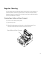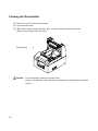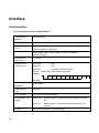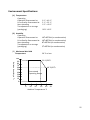
1
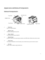
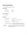
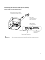
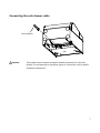
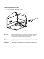
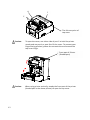
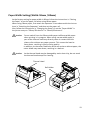
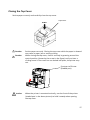
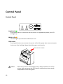
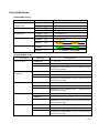
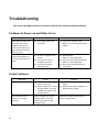
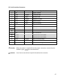
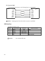
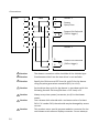
TH180
Thermal Printer
User Manual
All brand and product names mentioned in this document are trademarks of their
respective owners.
Copyright ©Wincor Nixdorf International GmbH, 2012
The reproduction, transmission or use of this document or its contents is not permitted without
express authority. Offenders will be liable for damages. All rights, including rights created by patent
grant or registration of a utility model or design, are reseverd.
Delivery subject to availability; technical modifications possible.
Contents
Appearance and Name of Components ......................................................... 1
Name of Components ..................................................................................... 1
Package Contents ............................................................................................ 2
Paper Specifications........................................................................................ 3
Paper Width .................................................................................................... 3
Paper Thickness ............................................................................................... 3
Paper Roll ........................................................................................................ 3
Preparation ..................................................................................................... 4
Connecting the Interface Cable (to the printer).............................................. 5
Printers with serial and USB interfaces....................................................... 5
Connecting the Interface Cable (to the PC) ..................................................... 6
Serial Interface ............................................................................................ 6
USB interface .............................................................................................. 6
Connecting the cash drawer cable .................................................................. 7
Connecting the Power Cable ........................................................................... 8
Installing the Printer ........................................................................................ 9
Horizontal Installation................................................................................. 9
Vertical Installation ..................................................................................... 9
Power On....................................................................................................... 10
Inserting Paper.............................................................................................. 11
Opening the Top Cover.................................................................................. 11
Paper Width Setting (Width: 58mm / 80mm) ............................................... 13
Attaching the Separator ........................................................................... 13
Attaching the Separator............................................................................ 14
Setting the Paper ........................................................................................... 15
Closing the Top Cover.................................................................................... 17
Control Panel ................................................................................................ 18
Control Panel ................................................................................................. 18
Error Indications ............................................................................................ 19
Paper Jam Prevention and Removal ............................................................ 20
Paper Jam Prevention.................................................................................... 20
Paper Jam Removal ....................................................................................... 20
If the Top Cover Does Not Open ................................................................... 21
Troubleshooting............................................................................................ 24
Problems at Power-on and Other Errors ....................................................... 24
Cutter Problems............................................................................................. 24
Printing Problems .......................................................................................... 25
Special Mode (Test Print, Setup Menu...) .................................................... 26
Test Print........................................................................................................ 26
Changing the Setup........................................................................................ 28
Exiting to Previous Level ........................................................................... 32
Exiting Directly to Setup Menu ................................................................. 34
Setup Settings ................................................................................................ 35
HEX Dump ...................................................................................................... 40
Command Trace............................................................................................. 41
Sample Print .................................................................................................. 42
Regular Cleaning ........................................................................................... 43
Cleaning Paper Holder and Paper Transport ................................................. 43
Cleaning the Platen Roller ............................................................................. 44
Cleaning the Thermal Head ........................................................................... 45
Interface ........................................................................................................ 46
Serial Interface............................................................................................... 46
USB Interface ................................................................................................. 48
Cash Drawer Connector ................................................................................. 49
Specifications ................................................................................................ 52
General Specifications ................................................................................... 52
Cutter Specifications...................................................................................... 54
Paper Roll Supply Specifications .................................................................... 54
Interface Specifications ................................................................................. 54
Environment Specifications ........................................................................... 55
Usage Precautions......................................................................................... 56
Paper Related Precautions ............................................................................ 56
Cutter Related Precautions............................................................................ 57
Barcode/2D Code Printing Precautions ......................................................... 57
USB Interface Usage Precautions .................................................................. 58
Installation Precautions ................................................................................. 58
Modular Type Connector Usage Precautions ................................................ 58
Safety Precautions ........................................................................................ 59
Warning Marks .............................................................................................. 59
Appearance and Name of Components
Name of Components
Release Lever
Top Cover
Middle Cover
Front Cover
Control Panel
Power Switch
AC Inlet
•
Top Cover
Opens to replace paper.
•
Release Lever
Used for opening the top cover.
•
Power Switch
Turns the printer power ON/OFF.
•
Control Panel
Contains switches for operating the printer and LEDs that indicate the printer status.
•
Front Cover
This can be removed in case of cutter jam or when the top cover does not open.
•
AC Inlet
Plug in the AC power supply cable here.
1
Package Contents
Quick Start Guide
Rubber Feet
(for vertical installation)
58mm Width Separator
2
Paper Specifications
Only use the thermal paper specified below.
Paper Width
• 80-mm-Paper
80mm01,0
• 58-mm-Paper
58mm01,0
Paper Thickness
• 65 - 85 m
Paper Roll
• Outside diameter:
Ø 83 mm or less
• Core diameter:
Ø 12 ±0,5 mm (inside) / Ø 18 ±0,5 mm
(outside)
• Printing surface:
outer surface of the roll
• Treatment of end of paper: The roll paper must not be glued to the core.
The end of the paper must also not be folded back.
Caution:
Do not use rolls that have rough sides or sides from which pieces
of paper extrude. Such paper may cause unstable paper feeding,
resulting in printer trouble.
3
Preparation
No printer cable is provided with the product. Obtain a printer cable suitable for the
product interface. If you have any question, consult your dealer. Before connecting
or disconnecting cables, make sure of the following:
(1)
(1) The power to the printer and all other devices connected to the
printer is turned off.
The AC adapter power cable has been unplugged from the outlet.
(2)
Caution:
When connecting cables or moving the printer, hold the middle part
of the printer cover on both sides. Holding the top cover may cause it
to open.
Top Cover
Middle Cover
4
Connecting the Interface Cable (to the printer)
Printers with serial and USB interfaces
USB Interface Cable Type-B
* Connect the printer to a PC
through this connector.
Serial Interface Cable
* Use the screws to secure it
in place after connection.
USB interface
Typ B connector
Power connector
Serial interface
connector
Cash drawer connector
Caution:
Do not connect both the serial and USB interfaces at the same time.
5
Connecting the Interface Cable (to the PC)
Serial Interface
(1) Connect the connector of serial interface cable to the serial port on the
computer as shown in the figure.
USB interface
(1) Connect the connector of USB interface cable to the USB port on the
computer as shown in the figure.
6
Connecting the cash drawer cable
Cash drawer cable
Caution:
This product uses a special-purpose modular connector for the cash
drawer. Do not attempt to use other types of connectors such as public
telephone connectors.
7
Connecting the Power Cable
(1) Connect the power cable to the AC inlet.
Power Cable
AC inlet
Caution:
Before connecting the power cable, turn off the power switches on
the printer and all the devices connected to the printer. Also, re
move the plug of the power cable from the outlet.
Caution:
Perform power cable connection with the device placed vertically for
easy operation.
Caution:
If the device is installed vertically, use a right-angled power cable.
(2) Insert the plug of the power cable into the outlet.
8
Installing the Printer
Both horizontal installation (the paper exit is on the topside) and vertical installation
(the paper exit is on the front side) orientations are available.
Horizontal Installation
Vertical Installation
If the printer is installed vertically, stick the rubber feet (included in the package) into
the round indents on the printer rear cover.
Rubber Feet
Caution:
Before sticking on the rubber feet, wipe off any dirt inside the
indents.
9
Power On
(1) Connect to the power cable.
(2) Turn on the power switch at the side of the printer.
After turning the power on, the POWER LED on the control panel will light up.
Control panel
Power Switch
10
Inserting Paper
Opening the Top Cover
(1) Pull the release lever in the direction of the arrow, and then open the top cover.
Top Cover
Release Cover
Caution:
Lift the cover until it is vertical so that it will stay open.
11
A
B
C
The fulcrum point of
top cover
Caution:
To open the cover, use either side of part C to hold the printer
steady and use part A or part B to lift the cover. To prevent your
fingers being pinched, please do not touch the area around the
top cover hinge.
Front part of Printer
(Shaded part)
Caution:
12
When using printer vertically, steady the front part of the printer
(shaded part in the above picture) to open the top cover.
Paper Width Setting (Width: 58mm / 80mm)
As the factory setting for paper width is 80mm, follow the instructions in "Setting
the Paper" to set the paper roll when using 80mm paper.
When using 58mm paper, first attach the separator in accordance with the instructions in "Attaching the Separator" and then set the paper roll.
Also, follow the instructions in "Changing the Setup" to set the "Paper Width" in
the printer setup to "58mm/35columns" or "58mm/32columns".
Caution:
Do not switch from the 58mm width paper to 80mm width paper
when printing is in progress. When using narrow-width paper, a
part of the thermal head may directly come in contact with the
platen roller without any paper present. This causes the head to
wear down, resulting in poor printing quality.
In addition, as the cutter blade also works on sections without paper, the
cutter blade may wear down, resulting in a bad cut.
Caution:
As the thermal head may be damaged by static electricity, do not touch
the thermal head except for cleaning.
Thermal Head
Roll Holder
13
Attaching the Separator
(1) Align the three lugs of the supplied 58mm width separator with the corresponding
holes on the printer body, then push it into place.
58mm Width Separator
Setting Hole
14
Caution:
Push the plate until it locks with a clicking sound and confirm that the
top side of the separator is horizontal.
Caution:
When moving the separator follow the instructions in the Special Mode
section to set the paper width and align it with the printing area.
Setting the Paper
(1) In the case of a new roll of paper, remove the glued portion and tape on the paper
roll.
When replacing the roll paper, first remove the old paper core.
Caution: Since the glued portion of the paper should not be printed on, remove
about one turn (about 30 cm) of the roll paper from the beginning so
that none of the remaining paper has glue on it.
Any adhesive or other matter remaining from the glue may adhere to
the thermal head and cause a problem, such as voids on printouts.
Therefore, do not forget to remove the glued portion of the paper.
(2) After inserting the new roll of paper with the orientation shown, pull the end of the
paper in the direction indicated by the arrow [1].
Platen roller
[1]
Top cover
Caution:
Pull the end of the paper so that it passes over the top of the cover.
Caution: Do not damage or dent the platen roller. Dents on the platen roller will
cause gaps in the printing and/or line feed failure.
15
Caution:
Setting the paper as shown in the following figures may cause paper or
printing jams.
The paper does not pass over the
top of the cover.
16
The paper has been set incorrectly.
Caution:
Do not use deformed roll paper. Using rolls such as those shown below
may cause trouble such as paper or printing jams.
Caution:
If the roll paper is loose (slack) as shown below, remove the slack before
using the roll. Using without removing the slack may cause paper or
printing jams, or result in failure to detect the paper near end condition.
Closing the Top Cover
Set the paper correctly and carefully close the top cover.
Push
Caution:
Caution:
Top Cover
Set the paper correctly. Closing the top cover while the paper is skewed
may cause a paper jam or messy printing.
When closing the top cover, close it securely by pressing around the
central position (shown by the arrow in the figure) until you hear a
clicking sound. If the cover has not locked into place, the printer may
not.
Front part of Printer
(Shaded part)
Caution:
When the printer is mounted vertically, use the front of the printer
(shaded part in the above picture) to hold it steady when opening
the top cover.
17
Control Panel
Control Panel
POWER LED( )
If the power switch is turned on and the printer is supplied with power, this LED
will light up.
ERROR LED( )
This LED lights up or blinks to indicate an error.
FEED Button
Pressing this button once causes the printer to feed the paper by an amount equivalent to one line. Holding it down feeds the paper continuously.
Rear of the Printer
Caution:
18
When the printer is mounted vertically, always hold the rear of the
printer when you press the FEED button to keep the printer steady
and prevent it from falling over.
Error Indications
Recoverable errors
Error State
No paper
Paper end
Cover open
Cutter jam
Paper near end
Head hot
LED Lamp
POWER ( )
ERROR ( )
POWER ( )
ERROR ( )
POWER ( )
ERROR ( )
POWER ( )
ERROR
( )
POWER
( )
ERROR
( )
Blinking Pattern
Constantly on
Constantly on
Constantly on
Constantly on
Constantly on
Constantly on
Constantly on
Remains unchanged.
Unrecoverable errors
Error State
Internal error
LED Lamp
POWER( )
ERROR( )
Blinking Pattern
—— — —
—————
Repetition of two blinks of the
blink of the lamp
Head not
installed
POWER( )
ERROR( )
—— — — —
———————
Repetition of three blinks of the
blink of the lamp
Low voltage
POWER( )
ERROR( )
POWER( )
ERROR( )
——————————
POWER( )
ERROR( )
lamp and one
—— — — — — —
————————————
Repetition of five blinks of the
blink of the lamp
Watchdog timer error
lamp and one
—— — — — —
Repetition of four blinks of the
blink of the lamp
Over voltage
lamp and one
lamp and one
—— — — — — — — — —
——————————————————
Repetition of eight blinks of the
blink of the lamp
lamp and one
19
Paper Jam Prevention and Removal
Paper Jam Prevention
Do not touch the paper while it is coming out or before cutting is complete. Pressing or
pulling the paper with your hand while it is coming out may cause a paper jam, bad cut,
or bad line feed.
Paper Jam Removal
In case of a paper jam, remove the paper as follows:
(1) Turn off the power switch to disconnect the printer from the power.
(2) Pull the release lever towards you, and then open the top cover.
If the top cover does not open, refer to the instructions in "If the Top Cover Does
Not Open" to remove the cutter jam.
(3) Press the printer and remove the jammed paper.
Caution: When removing paper, remove the paper slowly without pulling it
forcibly.
Caution: As the thermal head may be damaged by static electricity, do not touch
the thermal head. Also, do not touch the thermal head as it may still be
hot after printing.
(4) Set the paper correctly and carefully close the top cover.
Caution: Set the paper correctly. Closing the top cover while the paper is skewed
may cause a paper jam or messy printing.
Caution: When closing the top cover, close it securely by pressing around the
central position until you hear a clicking sound. If the cover has not
locked into place, the printer may not function.
(5) Turn on the power switch . Also, at this time confirm that the ERROR lamp has
turned off.
Caution: As printing data cannot be received while the ERROR lamp is on, firmly
close the top cover.
20
If the Top Cover Does Not Open
When the printer has stopped with the cutter blade exposed due to some abnormality
such as a paper jam, the top cover will not open.
In such a case, instead of opening it forcibly, perform the following steps:
(1) Turn off the power switch to disconnect the printer from the power.
(2) Turn the power on again. This causes the cutter to operate and may clear the paper
jam.
(3) Pull the release lever toward you to check whether the top cover opens. If so, turn
the power off again and follow the instructions from step (6) to clear the paper jam.
If the top cover still cannot be opened after the power is turned on, turn the power
off again and follow the instructions from step (4) to clear the paper jam.
(4) Remove the front cover by lifting it as shown by the arrow.
Top Cover
Front Cover
(5) Lift the protective sheet as indicated by arrow A and rotate the cutter gear in the
direction indicated by arrow B while pulling the release lever toward you.
If the auto-cutter blade fails to move despite rotating the cutter gear and the top cover
still will not open, pull the release lever toward you and rotate the cutter gear in the
opposite direction (indicated by arrow C) until the top cover is able to open.
21
Protective Sheet
Top Cover
Cutting Gear
Cutting Motor
Release Lever
Auto-cutter blade is
protruding
Top Cover can not be opened
Auto-cutter blade
is retracted
Top Cover can be opened
22
Caution:
Do not the touch the cutter motor, as it may still be hot after printing.
Caution:
Do not touch the auto cutter, as its blade end is sharp and dangerous.
Caution:
When you cannot open Top Cover with rotating Cutter Gear to either
direction, call your service provider.
(6) Open the top cover and remove the jammed paper while holding the printer
steady.
Caution:
When removing paper, remove the paper slowly without pulling it forcibly.
Caution:
As the thermal head may be damaged by static electricity, do not touch
the thermal head. Also, do not touch the thermal head as it may still be
hot after printing.
(7) . Set the paper correctly and carefully close the top cover.
Caution:
Set the paper correctly. Closing the top cover while the paper is skewed
may cause a paper jam or messy printing.
Caution:
When closing the top cover, close it securely by pressing around the
central position until you hear a clicking sound. If the cover has not
locked into place, the printer may not function.
(8) .Turn on the power switch. Also, at this time confirm that the ERROR lamp has
turned off.
23
Troubleshooting
This section provides solutions for printer malfunctions and print quality problems.
Problems at Power-on and Other Errors
Symptom
Cause
Solution
Although the power has
been turned on, the
POWER lamp on the
control panel does not
light up and the printer
does not start.
(1) The power cable is disconnected.
(1) Connect the power cable.
* Refer to “Connecting the Power
Cable”.
(.
The ERROR lamp on the
control panel lights up
and the printer does not
work.
(1) There is no paper in the
(1)
*
(2)
*
(3)
printer
(2) The top cover is not
completely closed.
(3) The thermal head is
excessively hot.
Set the paper.
Refer to “Inserting Paper”.
Close the top cover completely.
Refer to “Inserting Paper”.
Wait for the thermal head to
cool down.
Cutter Problems
Symptom
24
Cause
Solution
The paper is not cut.
(1) The cutter blade is damaged or worn out.
(2) Paper fragments or other
foreign matter are stuck
around the cutter or the
sliding section.
(1) Turn off the power and request
repair.
(2) Remove the paper fragments or
other foreign matter.
The cutter does not
return to its correct
position.
Paper fragments or other
foreign matter are stuck
around the cutter or the
sliding section.
Remove the paper fragments or
other foreign matter.
Printing Problems
Symptom
The printer does not
print.
Cause
(1) The imj nterface cable is
disconnected or broken.
(2) The printer setup is not correct.
Print is too dark or
blurred.
(1) Print density setting in the
printer setup is incorrect.
(2) The thermal head is damaged.
Print is too faint.
(1) Print density setting in the
printer setup is incorrect.
(2) The thermal head is damaged.
Printing is uneven.
(1) Paper fragments or other
foreign matter are stuck to the
heating elements of the thermal head.
(2) The setting of the printer setup
is incorrect.
(3) Foreign matter is stuck on the
platen roller.
(4) The thermal head is damaged.
Vertical marks appear on the printout.
(1) Foreign matter is stuck in or
dropped into the paper
transport.
(2) Foreign matter is stuck on the
thermal head.
(3) The thermal head is damaged.
Solution
(1) Connect the interface cable
correctly, or replace it.
* Refer to “Connecting the Interface
Cable”
(2) Amend the setting.
Example: Baud rate mismatch
* Refer to “Changing the Setup”.
(1) Set the printer at the suitable
print density and/or print speed
for the print paper.
* Refer to “Changing the Setup”.
(2) Turn off the power and request
repair.
(1) Set the printer at the suitable
print density and/or print speed
for the print paper.
* Refer to “Changing the Setup”.
(2) Turn off the power and request
repair.
(1) Check and clean the thermal
head. *Refer to “Cleaning the
Thermal Head “
(2) Set the printer at the suitable
print density and/or print speed
for the print paper.
* Refer to “Changing the Setup”.
(3) Remove the foreign matter from
the platen roller.
* Refer to “Cleaning the Platen
Roller”
(4) Turn off the power and request
repair.
(1) Clean the paper transport.
* Refer to “Cleaning Paper Holder
and Paper transport”
(2) Clean the thermal head.
* Refer to “Cleaning the Thermal
Head“
(3) Turn off the power and request
repair.
25
Special Mode (Test Print, Setup Menu...)
Test Print
Ensure that paper is set in the printer. Turn off the power switch on the printer,
then turn it on again while pressing the FEED button on the control panel. This outputs the following printout.
Caution: Press and hold the FEED button until the printer starts printing.
1.Test Print
2.Setup Menu
3.Hex Dump
4.Command Trace
5.Sample Print
6.End
Paper feed direction
Special Mode
<Set>
Press FEED button for the number of times
as the same as your selecting item,
wait more than 1 second.
Then Press the FEED button once (select 1. Test Print) to start a test print.
The printer automatically cuts the paper and stops after performing a set amount of
printing. To terminate the test print while in progress, press the FEED button. This
cuts the paper and terminates printing.
26
Test Print (Example)
Firmware Number KA02041-Jxxx
Firmware Version 01A
123456
Memory Switch 1
Power On Status
Receive
Busy CondiReceive Error
Auto LF
DSR(#6)Reset
INIT(#25)Reset
USB Soft Reset
Memory Switch 2
Cover Open Error
Error
Batch (COM IF)
Batch (Other IF)
Serial Number
ASB
Font-B
Print
Paper Width
Max
Print Density
Hardware
Error Alert
Buzzer Interval
Buzzer Repetition
Graph/User NV-MEM
Cut at CoverClose
PNE Detect
Interface
Baudrat
Format
Protocol
USB
%&
: ;
OP
d e
' (
< =
QR
f g
)
>
S
h
Enable
4KByte
Bufferfull
?Print
Disable
Disable
Disable
Enable
Paper feed direction
! " # $
5 6 7 8 9
J K L MN
_ ~ a b c
The Firmware Number and Firmware Version vary according to the model.
“123456”is an example serial number
Auto RecovAuto RecovEnable
Disable
Disable
Enable
Mode1
80mm/48
columns
180mm/s
100%
None
Pattern 2
Three
384KB/192KB
Disable
Enable
115200BPS
8NONE1
DSR/DTR
Printer
*
?
T
I
+ ,
@A
UV
j k
- . /
BCD
WX Y
l mn
0
E
Z
o
1
F
[
p
2
G
\
q
3
H
]
r
4
I
^
s
27
Changing the Setup
This section explains how to setup the printer without using a PC.
Setting Example
Select a higher print density
Print Density
Changed from 100% to 130%
Perform setup as follows:
1. Check the printer state prior to setting.
(1) The power is off.
(2) The paper roll is set.
(3) The cover is closed.
2. Ensure that paper is set in the printer. Turn off the power switch on the printer,
then turn it on again while pressing the FEED button on the control panel. This outputs the printout shown in the section before.
Then press the FEED button twice (to select 2. Setup Menu) enters setup mode
and prints the following menu.
Setup Menu
<Set>
Press FEED button for the number of times
as the same as your selecting item, and
wait more than 1 second.
<Return>
Continue to press FEED button more than
1 second.
28
Paper feed direction
1.Setting
2.Setup Print
3.Save & End
4.Default Set
3. Then press the FEED button once (to select 1. Setting) enters setting mode and
prints the following setting groups.
1.Memory Switch 1
2.Memory Switch 2
3.Print
4.Hardware
5.Interface
<Set>
Press FEED button for the number of times
as the same as your selecting item, and
wait more than 1 second.
Paper feed direction
Setting
<Return>
Continue to press FEED button more than
1 second.
4. Then press the FEED button three times (to select 3. Print) selects the Print group
and prints the following setting options.
Print
80mm/48columns
180mm/s
100
<Set>
Press FEED button for the number of times
as the same as your selecting item, and
wait more than 1 second.
<Return>
Continue to press FEED button more than
1 second.
Paper feed direction
1.Paper Width
2.Max Speed
3.Print Density
<Setup Menu>
Continue to press FEED button more than
3 seconds.
29
5. Then press the FEED button three times (select 3.Print Density) selects the Print
Density setting and prints the following Print Density settings.
Print Den-
100%
<Set>
Press FEED button for the number of times
as the same as your selecting item, and
wait more than 1 second.
<Return>
Continue to press FEED button more than
1 second.
<Setup Menu>
Continue to press FEED button more than
3 seconds.
30
Paper feed direction
1.70%
2.80%
3.90%
4.100%
5.110%
6.120%
7.130%
6.Then press the FEED button seven times (to select 7. 130%) returns to the Print
settings group.
Changed items are displayed in bold and underlined.
1.Paper Width
2.Max Speed
3.Print Density
80mm/48columns
180mm/s
130%
<Set>
Press FEED button for the number of times
as the same as your selecting item,
wait more than 1 second.
Paper feed direction
Print
<Return>
Continue to press FEED button more than
1 second.
<Setup Menu>
Continue to press FEED button more than
3 seconds.
To exit to the previous level (<Return>)
Go to next section.
To exit directly to the setup menu (<Setup Menu>)
Go to next but one section.
31
Exiting to Previous Level
Hold the FEED button down for 1 second or more until the buzzer sounds twice.
Release the FEED button after the buzzer sounds.
This returns to the previous level and prints the Setting group options.
Setting
<Set>
Press FEED button for the number of times
as the same as your selecting item,
wait more than 1 second.
<Return>
Continue to press FEED button more than
1 second.
32
Paper feed direction
1.Memory Switch 1
2.Memory Switch 2
3.Print
4.Hardwar
5.Interfac
Hold down the FEED button again for 1 second or longer until the buzzer sounds
twice. Release the FEED button after the buzzer sounds.
This returns to the previous level and prints the Setup Menu.
Setup Menu
<Set>
Press FEED button for the number of times
as the same as your selecting item, and
wait more than 1 second.
Paper feed direction
1.Setting
2.Setup Print
3.Save & End
4.Default Set
<Return>
Continue to press FEED button more than
1 second.
Proceed with pressing the FEED button three times.
33
Exiting Directly to Setup Menu
Hold the FEED button down for 3 seconds or more to return to the Setup
Menu.
Although holding down the FEED button for a long time causes the buzzer to
sound twice after 1 second, ignore this and continue to press the FEED button.
After about 3 seconds, the buzzer sounds three times and the following menu is
printed.
Setup Menu
<Set>
Press FEED button for the number of times
as the same as your selecting item, and
wait more than 1 second.
Paper feed direction
1.Setting
2.Setup Print
3.Save & End
4.Default Set
<Return>
Continue to press FEED button more than
1 second.
Proceed with the following step.
Pressing the FEED button three times (to select 3. Save & End) saves the settings,
cuts the paper, and then exits setup mode.
Caution:
If the power switch of the printer is turned off without selecting "Save &
End", any changes made will not be saved.
Checking the Settings
To check that the settings have been applied, follow the instructions in section 9.1 to perform a test print.
The test print includes a list of printer settings. Use this to confirm your changes.
34
Setup Settings
Setting Groups
Settings Group
Description
1
Memory Switch 1
Memory Switch 1 settings
2
Memory Switch 2
Memory Switch 2 settings
3
Print
Print settings
4
Hardware
Hardware settings
5
Interface
Serial and USB interface settings
Setting Items and Detailed Setting Items
(Note) Setup items and the default values depend on the printer model and/or area.
Memory Switch 1 Group
Item
Description
Setting Value
1
Power On Status
Specifies Power ON notification.
1
2
Enable
Disable
2
Receive Buffer
Specifies receiver buffer size.
1
2
45bytes
4Kbytes
3
Busy Condition
Sets the printer as BUSY (data
reception not available).
1
2
Buffer full
Offline/Buffer full
4
Receive Error
Specifies what to do when a receive error occurs using the serial
interface.
1
2
?Print
Ignore
5
Auto LF
Specifies whether the CR code
generates an automatic line feed.
1
2
Enable
Disable
6
DSR(#6)Reset
Specifies whether receiving DSR
(#6) via the serial interface triggers
a hardware reset.
1
2
Enable
Disable
7
INIT(#25)Reset
Specifies whether receiving INIT
(#25) via the serial interface triggers a hardware reset.
1
2
Enable
Disable
8
USB Soft Reset
Specifies whether a USB Soft Reset
triggers a hardware reset when
using printer class USB.
1
2
Enable
Disable
35
Memopry Swich 2 Group
1
Description
Cover Open
Recovery method for Cover Open Error
during print
1
2
Auto Recovery
Recovery by CMND
1
2
Auto Recovery
Recovery by CMND
Error
Setting Value
2
Error
What to do at power on or after recovery from error
"Auto Recovery": Perform auto recovery to enable data reception.
"Recovery by CMND": Discard any
received data until a reset command is
received.
3
Batch (COM IF)
Specifies whether to use batch printing
for the serial interface
1
2
Enable
Disable
4
Batch (Other IF)
Specifies whether to use batch printing
for the USB
1
2
Enable
Disable
5
Serial Number
Specifies iSerial Number notification for
USB
"Disable": Returns “0” as the iSerial
Number.
"Enable": Returns the manufacturing
serial number as the iSerial
Number
1
2
Enable
Disable
6
ASB
Specifies whether to enable the automatic status transmission function
(ASB: Automatic Status Back)
1
2
Enable
Disable
1
2
Mode1
Mode2
7
36
Item
Font-B
Specifies the number of columns for
font B (horizontal x vertical)
"Mode1"
"Mode2"
10x24
9x24
Print Group
Item
1
Paper Width
Description
Paper width and number of characters per line
Maximum print speed
2
Max Speed
The maximum for printing ladder
barcodes and two-dimensional
codes is 120mm/s.
Print density
3
Print Density
The smaller the value the lower the
print density.
The higher the value the higher the
print density.
Setting Value
1
2
3
4
80mm/48columns
80mm/42columns
58mm/35columns
58mm/32columns
1
2
3
4
5
6
7
8
9
100mm/s
110mm/s
120mm/s
130mm/s
140mm/s
150mm/s
160mm/s
170mm/s
180mm/s
1
2
3
4
5
6
7
70%
80%
90%
100%
110%
120%
130%
37
Harware Group
Item
Error Alert
1
*1
Description
Whether to sound a buzzer when an
error occurs
"None": Does not beep.
"One Time": Beeps four times.
"Continuous": Beeps continuously.
Setting Value
1
2
3
None
One Time
Continuous
1
2
3
4
5
Pattern 1
Pattern 2
Pattern 3
Pattern 4
Pattern 5
1
2
3
4
5
6
Zero
One
Two
Three
Four
Five
1
2
3
4
384KB/192KB
448KB/128KB
512KB/64KB
576KB/0B
The buzzer tone to use during printing
Buzzer Interval
2
*2
The buzzer beeps in the following
cases during printing:
• FEED button pressed while cover
open
• Buzzer command received
(ESC p 03h t1 t2 t3)
The number of buzzer beeps during
printing
Buzzer Repetiti3
on
*2
Zero specifies no buzzer.
The buzzer beeps in the following
cases during printing:
• FEED button pressed while cover
open
• Buzzer command received
(ESC p 03h t1 t2 t3)
NV graphic memory size and user NV
memory size
38
4
Graph/User NVMEM
5
Cut at Cover
Close
Whether to trigger the cutter when
the cover is closed.
1
2
Enable
Disable
6
PNE Detect
Whether to notify when near the
paper end
1
2
Enable
Disable
Specifies the size of the registration
area for graphics images and NV bit
images, and the size of the area for
storing any user data.
*1
"Error Alert"
The operation when a "continuous" buzzer tone is output is as follows:
(Note) To stop the buzzer during continuous beeping, press the FEED button.
• Recoverable Error (Excluding Paper Near End)
Continuous beeping of 500mSecON/200mSecOFF
• Hardware Error
Continuous beeping of 1000mSecON/500mSecOFF
*2
"Buzzer Interval"
The buzzer patterns are as follows:
• Pattern 1
40msON / 120msOFF
• Pattern 2
140msON / 140msOFF
• Pattern 3
200msON / 200msOFF
• Pattern 4
10msON / 50msOFF
• Pattern 5
30msON / 50msOFF
Interface Group
Item
1
Baud rate
Description
Setting Value
Baud rate for the serial interface
1
2
3
4
5
6
7
2400BPS
4800BPS
9600BPS
19200BPS
38400BPS
57600BPS
115200BPS
7EVEN1
7ODD1
8NONE1
8ENEN1
8ODD1
2
Format
Data format for the serial interface
1
2
3
4
5
3
Protocol
Buffer control protocol for the
serial interface
1
2
DSR/DTR
XON/XOFF
4
USB
Class for USB interface
1
2
Printer
V-COM
39
HEX Dump
Ensure that paper is set in the printer. Turn off the power switch on the printer,
then turn it on again while pressing the FEED button on the control panel. This
outputs the printout shown in section 9-1.
Pressing the FEED button three times (select 3. Hex Dump) enters HEX dump
mode. This mode prints all the data sent to the printer as hex code. It is useful for
checking whether the control codes being sent to the printer by the PC program
are correct.
To clear this mode, turn the power switch off and on again.
HEX Dump Print (Example)
Hex Dump
000000 1B 40 1B 4D 02 1B 74 01 [email protected].
Address
40
Hex
ASCII
Command Trace
Ensure that paper is set in the printer. Turn off the power switch on the printer,
then turn it on again while pressing the FEED button on the control panel. This
outputs the printout.
Pressing the FEED button four times (select 4. Command Trace) enters command
trace mode.
This mode prints all the data sent to the printer in ASCII format (with ESC/POS
command explanations). It can be used to analyze the ESC/POS commands sent to
the printer by the PC program.
To clear this mode, turn the power switch off and on again.
Command Trace Print (Example)
Command Trace
<1 B 40 :Initialize printer (ESC @)>
<1 B 4D 0 2:Set ANK font C (ESC M n)>
<1 B 74 8 0:Set character code table (ESC t n)>
<1 D 42 0 0:Disable reverse printing (GS B n)>
<1 B 61 0 2:Set justification RIGHT (ESC a n)>
<1 C 2E :Reset kanji mode (FS .)>
Fujitsu Isotec
<0 A :Print and line feed (LF)>
a. Undefined commands or commands with abnormal command parameters are treated as errors and printed with background and foreground reversed.
b. Meaningless and unnecessary commands are printed with an underline as a warning.
c. Command codes are printed in bold.
41
Sample Print
Ensure that paper is set in the printer. Turn off the power switch on the printer,
then turn it on again while pressing the FEED button on the control panel. This
outputs the printout shown in section 9-1.
Pressing the FEED button five times (select 5. Sample Print) enters sample
print mode. This mode prints an explanation of FEED button operation, performs a
paper cut, and then prints sample patterns. (The FEED button explanation is only
printed at the first time.).
" Press FEED button.
Short : Next pattern
Long
: Same pattern"
After printing, pressing the FEED button briefly (less than one second) prints the
following samples, one at a time.
* "Receipt" "Coupon" "Bar Code" "Receipt" in turn. (Printing pauses
after each sample. Press the FEED button to print the next sample.)
Pressing the FEED button for a long time (one second or longer) prints the previous
sample again.
To clear sample print mode, turn the power switch off and on again.
Sample print mode performs a cut after each sheet is printed.
Sample print mode uses the 80mm or 58mm pattern depending on the paper width setting in setup.
If a recoverable error occurs, the sample print resumes after recovery.
42
Regular Cleaning
The print quality may be impaired by paper particles, dust, or other material. To
avoid this problem, remove any paper particles or dust from the paper holder,
the paper transport, the platen roller, and the thermal head as described below.
Perform cleaning every six months.
Cleaning Paper Holder and Paper Transport
(1) Be sure to turn off the printer power.
(2) Open the top cover.
(3) Wipe off any dust, paper particles, glue, or other foreign material from
the paper holder and paper transport using a soft, dry cloth
Paper Holder and Paper Transport
43
Cleaning the Platen Roller
(1) Be sure to turn off the printer power.
(2) Open the top cover.
(3) Wipe off any dust, paper particles, glue, or other foreign material from the
platen roller using a soft, dry cloth.
Platen Roller
Caution:
44
Do not damage or dent the platen roller.
Dents on the platen roller will cause incomplete printing and/or line feed
failure.
Cleaning the Thermal Head
(1) Be sure to turn off the printer power.
(2) Open the top cover.
(3) Using an alcohol solvent, remove black paper particles and other residue
from the surface of the thermal head
Thermal Head
Caution: The thermal head can easily be damaged. Clean it carefully using a soft
cloth to avoid any damage.
Caution: The thermal head is still hot immediately after printing. Leave it to cool
for about ten minutes before cleaning.
Caution: The thermal head may be damaged by static electricity. Take care to
avoid exposing it to static electricity.
Caution: Wait until alcohol from the cleaning solvent has thoroughly dried before
turning on the printer power.
Caution: Use only alcohol or isopropyl alcohol solvents.
45
Interface
Serial Interface
(1) Transmission Interface Specifications
Transmission
Method
Asynchronous
Line Type
Full duplex
Input/Output
Circuit
Input: MAX211 Equivalent
Output: MAX211 Equivalent
Baud Rate
2400, 4800, 9600, 19200, 38400, 57600, 115200BPS
(Setup Settings)
Transmission
Code Type
7 or 8 bits
Transmission
Code Format
Start bits:
1 bit
Stop bits:
1 bit
Data bits:
7 or 8 bits (Setup Settings)
Parity: NONE, ODD, EVEN (Setup Settings)
Mark(1)
ST
b0
b1
b2
b3
b4
b5
b6
b7
PT SP
Space(0)
46
Transmission
Sequence
LSB to MSB
Transmission
Code
JIS code
Error Control
Parity check (Setup Settings)
Connection Line
Length
Max. 15m: (When power is supplied from the power connector)
Max. 2m: (When power is supplied from the interface connector)
Protocol
DSR/DTR, XON/XOFF (Setup Settings)
(2) Serial Interface Connector
Pin No.
Signal Name
Direction
-
Signal Line Name
1
SG
2
TXD
Output
Signal Ground
Transmit Data
3
RXD
Input
Receive Data
4
RTS
Output
Request to Send
5
CTS
Input
Clear to Send
6
DSR
Input
7
SG
-
Signal Ground
8~12
N.C
-
No Connection
13
SG2
-
+24V Ground
14
SG2
-
+24V Ground
15~17
Data Set Ready
N.C
-
No Connection
18
+24V
-
Mechanical Drive Power
19
+24V
-
Mechanical Drive Power
20
DTR
21~24
N.C
25
INIT
Output
Input
Data Terminal Ready
No Connection
Forcible Reset Signal
Caution: When the power is supplied from the power connector, ensure the pins
shaded in grey
are not connected.
Caution:
Use a lock screw with an imperial thread on the connector
47
(3) Connection Cable
The connection setup shown in the following figure is recommended.
Host
FG <
TXD<
RXD<
RTS<
CTS<
DSR<
DTR<
SG <
>FG
>TXD
>RXD
>RTS
>CTS
>DSR
>DTR
>SG
Printer
Caution: Supplying power from the interface connector is prohibited.
USB Interface
(1) Type-B Connector: 4 Pins
Pin No.
Signal Name
Signal Line Name
1
VBUS
Input
2
D-inB
Input/Output
D-
3
D+inB
Input/Output
D+
4
SG
Caution:
48
Direction
-
Use a shielded USB cable
VBUS
Signal Ground
Cash Drawer Connector
Pin No.
Signal Name
Direction
Signal Line Name
1
FG
-
Frame Ground
2
*DRD1
Output
Drawer Kick Drive Signal 1
3
DRSNS1
Input
Drawer Sense Signal 1
4
+24V
-
Drive Power
5
*DRD2
Output
Drawer Kick Drive Signal 2
6
SG
-
Signal Ground
1
6
<Connecting side>
49
<Connection>
Printer
1
Cable
3
2
6
3
2
4
4
Drawer 1
Drawer
Open/Close
Drawer Kick Solenoid
(24 or bigger)
5
6
Drawer 2
5
4
Caution:
Caution:
The drawer connection cable should be of the shielded type.
Simultaneous drive from the two drives is not available.
Caution:
Specify the ON time and OFF time (t1 and t2) for the drawer
using the pulse generation command (ESC p m t1 t2).
Caution:
Set the drive duty cycle for the drawer in accordance with the
following formula: ON time/(ON time + OFF time) 0.2
Caution:
Always use printer power (connector pin 4) for the drawer
power.
Use a drawer kick solenoid with a resistance value of at least
24 . If it is under 24 , the solenoid may be damaged by excess
current.
This product uses a special-purpose modular connector for the
cash drawer and customer display connector. Do not attempt
Caution:
Caution:
50
Drawer Kick Solenoid
(24 or bigger)
to use other types of connectors such as public telephone
connectors.
51
Specifications
General Specifications
(1) Printing Method: Direct Line Thermal Printing
(2) Print Speed: Maximum 180 mm/s (Monochrome only)
(3) Print Resolution: 8dot/mm (0.125mm)
(4) Relationship between Number of Print Column and Character Size
Body face ((Width)x(Height) dot
Paper width: 58mm
32 column printing
35 column printing
ANK: Font A
32 columns: 12x24
35 columns: 12x24
ANK: Font B
38 columns: 10x24
42 columns: 9x24
42 columns: 10x24
46 columns: 9x24
ANK: Font C
48 columns: 8x16
52 columns: 8x16
ANK: Font A
Extension Font
32 columns: 12x24
35 columns: 12x24
ANK: Font B
Extension Font
38 columns: 10x24
42 columns: 9x24
42 columns: 10x24
46 columns: 9x24
)
52
Body face ((Width)x(Height) dot
Paper width: 80mm
42 column printing
48 column printing
ANK: Font A
42 columns: 12x24
48 columns: 12x24
ANK: Font B
51 columns: 10x24
56 columns: 9x24
57 columns: 10x24
64 columns: 9x24
ANK: Font C
64 columns: 8x16
72 columns: 8x16
ANK: Font A
Extension Font
42 columns: 12x24
48 columns: 12x24
ANK: Font B
Extension Font
51 columns: 10x24
56 columns: 9x24
57 columns: 10x24
64 columns: 9x24
(5) Character Sets
Alphanumeric (95), Extension Graphic (128×20 Page), International Character (48),
Special Character (845)
(6) Character Size
Body face
Letter face
(Width)x(Height)
dot
(Width)x(Height)
mm
(Width)x(Height)
dot
(Width)x(Height)
mm
ANK: Font A
12 x 24
1.5 x 3.0
11 x 22
1.375 x 2.75
ANK: Font B
10 x 24
9 x 24
1.25 x 3.0
1.125 x 3.0
9 x 17
9 x 17
1.125 x 2.125
1.125 x 2.125
ANK: Font C
8 x 16
1.0 x 2.0
8 x 13
1.0 x 1.625
ANK: Font A
Extension Font
12 x 24
1.5 x 3.0
12 x 24
1.5 x 3.0
ANK: Font B
Extension Font
10 x 24
9 x 24
1.25 x 3.0
1.125 x 3.0
9 x 22
9 x 22
1.125 x 2.75
1.125 x 2.75
(Note)
Print Column, Character Size and Character Sets depend on the printer
model and/or area.
53
Outline View
Cutter Specifications
(1) Cutting Method: Partial cut (the paper remains connected at one point)
Caution:
Do not use the cutter continuously at a rate exceeding 10 cuts per minute (1 cut per 6 seconds or more). Excessive use may cause a malfunction.
Paper Roll Supply Specifications
(1) Loading Method: Rolls are loaded manually.
(2) Paper Near End: Detected when the remaining paper length is inadequate.
Caution:
Core diameter 18mm is supported.
Interface Specifications
(1) Serial (RS-2332C)
(2) USB (USB 2.0 Full-speed)
54
Environment Specifications
(1) Temperature
Operating
Operation Guaranteed at:
Print Quality Guaranteed at:
Non-operating
Transportation or storage
(packaging):
0 °C – 40 °C
5 °C – 35 °C
-5 °C – 60 °C
(2) Humidity
Operating
Operation Guaranteed at:
Print Quality Guaranteed at:
Non-operating:
Transportation or storage
(packaging)
10%-95%RH (no condensation)
10%-85%RH (no condensation)
8%-95%RH (no condensation)
-20°C - 60°C
5%-95%RH (no condensation)
(3) Maximum Wet Bulb
Temperature
Relative Humidity in %
100
90
80
70
60
50
40
30
20
10
0
29 °C or less
30 °C/95 %
40 °C/65 %
Guaranteed
Operating Range
0
10
20
30
40
50
Ambient Temperature °C
55
Usage Precautions
Paper Related Precautions
(1) High printing rates may cause blurred printing. Choose a suitable printing rate
to avoid blurring. Alternatively, set a suitable combination of print speed and
print density to avoid blurring.
(Refer to chapter “Changing the set up”.)
(2) Printing characters from a non-standard character set in a thin serif or similar
font will result in the characters appearing very faint. Use a bold sans serif
font.
(3) To achieve quality printing without uneven pitch (expansion or contraction),
feed the paper 1mm (8 dots) or more when restarting printing or after cutting
the paper.
(4) In sequential printing, slow data transfer may cause white lines to run across
the print, as printing and pausing are repeated alternately. If print quality has
priority, use the Batch Print mode ("Batch (COM IF)", "Batch (OTHER IF)").
(Refer to chapter “Changing the Setup”.)
(5) The top margin can be set to either 12mm or 3mm by a command. If the top
margin is set to 3mm, be sure to remove the printed paper each time the
printing and cutting operation is completed as rollback of paper takes place
before printing. If printed and cut paper is not removed, the partial cut section
may be torn or the cut surface may be folded causing a paper jam. Also, use at
least 30 mm of paper for each transaction.
(6) Setting a high value for print density (110 % and over) can result in blurred or
uneven printing at low temperatures, depending on the printing pattern. If
print quality has priority, print at a lower speed.
(Refer to chapter “Changing the Setup”.)
(7) Do not switch from narrower paper to wider paper (e.g. 58mm to 80mm)
when printing is in progress. When using narrow-width paper, a part of the
thermal head may directly come in contact with the platen roller without any
paper present. This causes the head to wear down, resulting in poor printing
quality. In addition, as the cutter blade also works at sections without paper,
the cutter blade may wear down, resulting in a bad cut. Do not change paper
width when printing is in progress.
(8) If the paper has been left in the printer for a long time, it may deform and
cause faint printing. Therefore, if the paper has been left for a long time, feed
the paper forward by 20-30mm before printing.
56
(9) If non-recommended paper is used, print quality and/or the thermal head life
cannot be guaranteed. In particular, use of paper containing “Na+, K+, or Cl-”
may significantly shorten the life span of the thermal head.
(10) Using a non-recommended AC adapter may cause blurred and/or uneven
printing, so use only the recommended adapter.
(11) The paper may get marked during paper changing or when the top cover is
shut, so feed the paper forward by 20-30mm before printing.
Cutter Related Precautions
(1) Do not use the cutter continuously at a rate exceeding 10 cuts per minute (1
cut per 6 seconds or more). Excessive use may cause a malfunction.
(2) Do not remove paper while it is still being cut. Doing so may cause problems
such as a paper jam.
(3) If the top margin is set at 3mm, be sure to remove the printed paper each
time the printing and cutting operation is completed as roll back of the printer
paper takes place before printing. Not doing so may cause problems such as a
paper jam.
Barcode/2D Code Printing Precautions
(1) When using thick paper, the printing speed and density should be adjusted
and readability should also be checked before using the printer as thick paper
may cause blurring depending on the usage environment and the humidity.
(Refer to chapter “Changing the Setup”.)
(2) For 2D codes, adjust the printing speed and density to obtain a good recognition rate. As readability varies depending on the module width, print density,
ambient temperature, type of thermal roll paper, and reader performance,
check this before using the printer.
(Refer to chapter “Changing the Setup”.)
(3) If a barcode is printed at the top of the printer paper when it is first fed, or at
the bottom when paper feeding is completed, readability should be checked
as accuracy in paper feeding may become unstable.
57
USB Interface Usage Precautions
(1) Connect the printer directly to the host computer.
(2) Be sure to turn on the printer power before printing.
(3) If an error occurs during printing, recover the printer from the error, and then
retry printing.
(4) Do not turn off the printer or disconnect the USB cable while printing is in
progress. Using the host computer to set Stand-by mode, Sleep mode, Suspend mode or Pause mode is not recommended.
If the printer does not work properly even after implementing the above, try
re-connecting the USB cable or turning on the printer power again. If the
printer still does not print properly, restart the host computer.
Installation Precautions
(1) Use the printer indoors only. Outdoor usage may cause printer malfunction
due to dust or other factors.
(2) When connecting a cable to the printer or shifting the position of the printer,
perform the operation while holding the middle cover of the printer at the
sides using both hands. If you perform the operation holding the top cover,
the top cover may open.
Modular Type Connector Usage Precautions
(1) This product uses a special-purpose modular connector for the cash drawer
and customer display connector. Do not attempt to use other types of connectors such as public telephone connectors.
58
Safety Precautions
Warning Marks
This document uses the following warning marks in order to ensure safe and
correct use of the product and to prevent any harm or damage to you or to
others.
Warning
Used for instructions intended to alert
the user to the risk of death or severe
injury should the product be used improperly without paying attention to this
mark.
Caution
Used for instructions intended to alert the
user to the risk of injury or material damage
should the product be used improperly without paying attention to this mark.
Graphic Symbols Used and their Meanings, with Examples
The
symbol alerts the user to warnings and cautions. The specific meaning of the symbol is determined by the design contained
within the triangle (in this example, caution for electric shock).
symbol alerts the user to actions that must never be carThe
ried out (prohibited action). The specific action that is prohibited is
indicated inside or to the side of the circle (in this example, disassembly is prohibited).
The symbol
alerts the user to actions that must necessarily be
performed. The specific action is indicated by the design contained
within the circle (in this example, the power plug must be removed from the outlet).
59
Warning
When connecting the cash drawer cable, do not use any method not specified
in the instruction manual. This may result in fire or electric shock.
Do not place metals or vessels containing water, such as a vase, flower pot or
cup on the top of, or near the product, or pour water on it.
This may result in electric shock or fire.
Do not place this product in places with high humidity, dust, smoke or bad
ventilation, or in places with fire hazards. This may result in electric shock or
fire.
When connecting the AC adapter, do not use voltages outside the range indicated on the adapter. In addition, avoid using multiple cords connected to one
outlet. This may result in electric shock or fire.
Do not insert or remove the power plug using wet hands.
This may result in electric shock or fire.
Do not scratch or tamper with the power cable.
Placing heavy objects on the power cable, pulling it, bending it forcibly, twisting it, or tampering with it can damage the power cable and result in fire or
electric shock. Do not insert or drop foreign matter, such as metals or combustible materials, into the product from its aperture. This may result in fire or
electric shock.
60
In case of emergency involving heat, smoke or acrid fumes occurring, immediately turn off the power switch, and remove the power plug from the outlet.
Request the sales company (or maintenance service center) for repair after
confirming the smoke has gone. Users must under no circumstances whatsoever try to repair the product due to the dangers involved. Using the product
in the abnormal state without taking any corrective action may result in fire or
electric shock.
If any foreign matter (such as a piece of metal or water or other liquids) enters
the product, immediately turn off the power switch and remove the power
plug from the outlet. Afterwards, contact the sales company (or maintenance
service center). This may result in fire or electric shock if no action is taken.
When the product is dropped, or if the cover or some other part is damaged,
turn off the power switch, and remove the power plug from the outlet. Afterwards, contact the sales company (or maintenance service center).
Using the product without take any corrective action may result in fire or
electric shock.
When inserting the power cable into the AC adapter to connect the product, be
sure to confirm that the product power switch has been turned off. Also, when
inserting it into the outlet, confirm that the AC adapter is properly connected
to the product. Not doing so result in electric shock.
In order to prevent any hazards from the vinyl bag that packages this product,
please place it out of the reach of children.
In case of any accident with the bag, please consult a doctor immediately.
If any dirt is found on or around the metal pins of the power plug, wipe it off
using a dry cloth. Not doing so may result in fire.
Do not alter the product in any way. For internal check or repair, please request the sales company (or maintenance service center). There are high
voltage parts and sharp parts inside which can cause electric shock or injury.
61
-
-
Caution
Do not place heavy objects on the product.
This may destroy the balance and cause the product to fall over or down, resulting in injuries.
Do not locate the product on a place with severe vibration, or on an unstable or
inclined surface. The product may fall over or down, resulting in injuries.
Do not leave the product in high-temperature locations, such as directly under
the sun or near a heater, for long periods of time. High temperature may cause
the cover or other parts to be heated, deformed, or melted, and the temperature inside the product may also rise, resulting in fire.
Do not open the cover of the print section of the device and insert any
objects including your fingers during or immediately after use. This
may result in injury or burns. Do not touch the print head or motor
during or immediately after printing.
This may result in burns.
During printer operation, do not touch the movable parts, such as gears or cutters. Touching movable parts may result in injury.
Do not touch the cutter blade.
As there is a cutter at the paper exit, do not attempt to insert your hands inside
it at any time, whether or not the printer is in operation.
Do not open the cover of the print section of the device and touch the print
head during or immediately after use., This may result in injury or burns.
62
When shifting the product, be sure to remove the power plug from the outlet.
In addition, also remove the connection cable, etc. Pay adequate attention to
your feet while performing the operation.
Scratching the power cable may result in electric shock or fire, and
injuries may also be caused if the product falls over or down.
When removing the power plug, instead of pulling the electric cord, be sure to
remove it by gripping the power plug.
If the power cable is pulled, the core of the electric cord may become exposed
or broken, resulting in fire or electric shock.
When the weather conditions indicate a chance of a lighting strike, be sure to
remove the power plug from the outlet for safety.
Not doing so may result in fire.
When not using the device for a long time, be sure to remove the power plug
from the outlet for safety.
Not doing so may result in fire.
Firmly insert the power plug into the outlet.
An improper connection may result in fire or electric shock.
63
Wincor Nixdorf International GmbH
D-33094 Paderborn
Order No: 01750236263A