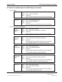
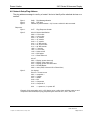
1
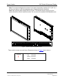
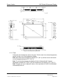
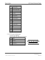
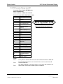
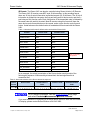
ELECTRONIC REVISION CONTROLLED Document Number 103629 Rev C Rosen Aviation 2401 Series Widescreen Display Technical Manual, 2401 Series Widescreen Display © 2010 by Rosen Aviation, LLC All Rights Reserved The information contained herein is proprietary to Rosen Aviation, LLC. No part of this publication may be reproduced, transmitted, transcribed, stored in a retrieval system, or translated into any language in any form by any means without the written authorization from Rosen Aviation, LLC, except as allowed under copyright laws. Disclaimer of Liability The information contained in this document is subject to change without notice. Because we are continuously improving and adding features to our products, Rosen Aviation, LLC reserves the right to change specifications without prior notice. Rosen Aviation, LLC shall not be liable for technical or editorial errors or omissions contained herein. Rosen Aviation, LLC 1020 Owen Loop South Eugene, OR 97402 541.342.3802 888.668.4955 Fax: 541.342.4912 www.rosenaviation.com Document Number: 103629 Template: 4.2.3-6-FM; Revision A; 16 May, 2005 Revision: Date: 06/11/10 C Page 2 of 37 Rosen Aviation 2401 Series Widescreen Display Contents 1. INTRODUCTION .................................................................................................................5 1.1. Product Information ......................................................................................................5 2. INSTALLATION GUIDELINES ...........................................................................................5 2.1. Cooling and Ventilation .................................................................................................5 2.1.1. Fans .......................................................................................................................................7 2.2. Electrical Requirements ................................................................................................8 3. VIDEO CONNECTIONS ......................................................................................................8 3.1. Pinout Connections .......................................................................................................8 3.1.1. P1 Connector DVI Input .........................................................................................................8 3.1.2. P2 Connector Auxiliary Input .................................................................................................9 3.1.3. P3 Connector Primary Input DC ......................................................................................... 10 3.1.4. P4 Connector Auxiliary Control .......................................................................................... 11 3.1.5. Control Inputs ...................................................................................................................... 11 4. RS-485 INFORMATION ....................................................................................................13 4.1. Communication Protocol .............................................................................................13 4.2. Packet Format ............................................................................................................13 4.3. Packet Timing .............................................................................................................13 4.4. Wiring..........................................................................................................................13 4.5. Packet Format Description for 2401 Display Commands............................................14 4.5.1. Power .................................................................................................................................. 14 4.5.2. Input Source Selection........................................................................................................ 14 4.6. Network Setup/Ping Address ......................................................................................15 5. TECHNICAL SETUP – TECHNICIAN ON-SCREEN DISPLAY CONFIGURATION .........16 5.1. Main Menu (Configuration) .........................................................................................17 5.2. Monitor Info .................................................................................................................17 5.3. Diagnostics Menu .......................................................................................................18 5.3.1. Self-test ............................................................................................................................... 18 5.3.2. Measure Video Levels ........................................................................................................ 18 5.3.3. Input Scan ........................................................................................................................... 21 5.4. Advanced Settings ......................................................................................................22 5.4.1. Start-up Settings ................................................................................................................. 22 5.4.2. Clock Settings ..................................................................................................................... 24 5.4.3. Source Setup ...................................................................................................................... 24 5.4.4. Session Records ................................................................................................................. 26 5.4.5. Network Settings ................................................................................................................. 27 5.4.6. Restore Defaults ................................................................................................................. 28 Document Number: 103629 Template: 4.2.3-6-FM; Revision A; 16 May, 2005 Revision: Date: 06/11/10 C Page 3 of 37 Rosen Aviation 2401 Series Widescreen Display 6. VIDEO SETTINGS ............................................................................................................29 6.1. Video Settings.............................................................................................................29 6.1.1. Top Menu Bar ..................................................................................................................... 29 6.1.2. Composite Menu Settings................................................................................................... 29 6.1.3. VGA Menu Settings ............................................................................................................ 31 6.1.4. Picture-in-Picture and Picture-and-Picture Modes ............................................................. 32 6.1.5. OSD Position Settings ........................................................................................................ 32 6.1.6. Language Settings .............................................................................................................. 33 6.1.7. Factory Reset Options ........................................................................................................ 33 7. TECHNICAL REFERENCES AND SUPPORT .................................................................34 7.1. Definitions ...................................................................................................................34 7.2. Troubleshooting ..........................................................................................................35 7.3. Specifications..............................................................................................................36 7.3.1. HDCP Resolutions .............................................................................................................. 36 7.4. DO-160E Qualifications ..............................................................................................37 7.5. Technical Support .......................................................................................................37 8. REVISION HISTORY ........................................................................................................37 Document Number: 103629 Template: 4.2.3-6-FM; Revision A; 16 May, 2005 Revision: Date: 06/11/10 C Page 4 of 37 Rosen Aviation 2401 Series Widescreen Display 1. INTRODUCTION This manual describes how to install the Rosen 2401 series Widescreen Display onto your aircraft. It contains everything you need to know to wire the display and confirm that it is functioning correctly. Note that installation and service should be performed only by trained and qualified personnel. 1.1. Product Information The following documentation for the 2401 series is available on the Rosen web site at www.rosenaviation.com. Outline and Installation Drawings Technical Manuals User’s Guide Optional Controllers (sold separately): External 7-button serial controller (P/N 0300-408) Universal color display remote (P/N 0500-015) From the Rosen Aviation home page, select the Products tab and browse by product category. 2. INSTALLATION GUIDELINES Mounting options for this display are shown in the following figures: Mount using all side mounting holes, or Mount using all top and bottom mounting holes (do not block vent holes) 2.1. Cooling and Ventilation The monitor is cooled by the flow of air or forced convection. Cooling fans are automatically regulated per an internal temperature sensor to provide forced convection cooling. You must take special care with the installation to provide a proper environment for airflow. Keep all vent holes unobstructed to allow the unit to run cooler. If the display must be sealed in a bulkhead, gasper air cooling is recommended below the monitor to prevent over temperature operating issues. In cases where no gasper air is available, provide for intake (below monitor) and exhaust venting (above monitor) to cabin. A minimum of 1 ft3 of volumetric air space is also recommended inside the bulkhead. Monitor vents: The monitor has vent openings on the top, bottom, back and side surfaces. For best thermal performance, ensure that all vent holes are unobstructed to allow free airflow. Document Number: 103629 Template: 4.2.3-6-FM; Revision A; 16 May, 2005 Revision: Date: 06/11/10 C Page 5 of 37 Rosen Aviation 2401 Series Widescreen Display Note: The monitor backlight will shut down if the internal temperature reaches 156° F [69° C]. It will not come back on until the temperature drops 3 degrees below the threshold. Note: Each mounting hole includes a #10-32 screw. To install the monitor, remove only the screws that will be used to install the monitor. Do not remove the smaller #4-40 flathead screws. Figure 1 Exterior vents for bulkhead mounts There must be cutouts over vent holes. (Dimensions shown in Figure 2 are in inches.) Warning! ! Document Number: 103629 Template: 4.2.3-6-FM; Revision A; 16 May, 2005 Maximum screw penetration depth allowed: Top .50 inches Bottom .50 inches Sides .50 inches Revision: Date: 06/11/10 C Page 6 of 37 Rosen Aviation 2401 Series Widescreen Display Figure 2 Dimensional requirements 2.1.1. Fans Cooling fans are located near vents in the case. The fans react to an internal temperature sensor, turning on or off as temperature dictates. Note: When the internal temperature reaches 90° F [32° C], the fans turn on and remain on until temperature drops to 87° F [31° C]. Note: To avoid product damage, the display will shut off automatically if internal temperature exceeds 156° F [69° C]; the unit remains off until cooled to 153° F [66° C]. Note: Through use of an air pressure sensor, at the equivalent of 20,000 ft, the backlight automatically shuts off. Document Number: 103629 Template: 4.2.3-6-FM; Revision A; 16 May, 2005 Revision: Date: 06/11/10 C Page 7 of 37 Rosen Aviation 2401 Series Widescreen Display 2.2. Electrical Requirements Voltage: 28VDC Max Power Consumption: 135W (DC) Do not plug or unplug the display connector while power is applied. 3. VIDEO CONNECTIONS 3.1. Pinout Connections The 2401 display uses connectors P1—P4, as shown below. P2 P1 DVI P3 Auxiliary inputs P4 28V power Composite VGA Auxiliary controls 24" Widescreen Display 3.1.1. P1 Connector DVI Input Connector Type: DVI-I female Rosen Connector Kit: 0300-029 (sold separately) Pin # Signal 1 T.M.D.S. Data2– 2 T.M.D.S. Data2+ 3 T.M.D.S. Data2 shield 4 N/C 5 N/C 6 DDC clock (DVI) 7 DDC data (DVI) 8 N/C Document Number: 103629 Template: 4.2.3-6-FM; Revision A; 16 May, 2005 1 6 7 16 17 24 C1 C2 C3 C4 C5 Rear view of P1 DVI Input Connector Revision: Date: 06/11/10 C Page 8 of 37 Rosen Aviation 2401 Series Widescreen Display P1 Connector DVI Input cont. 9 T.M.D.S. Data1 – 10 T.M.D.S. Data1 + 11 T.M.D.S. Data1 shield 12 N/C 13 N/C 14 5V power 15 GND for 5V 16 Hot plug detect 17 T.M.D.S. Data0 – 18 T.M.D.S. Data0 + 19 T.M.D.S. Data0 shield 20 N/C 21 N/C 22 T.M.D.S. Clock shield 23 T.M.D.S. Clock + 24 T.M.D.S. Clock – C1 N/C C2 N/C C3 N/C C4 N/C C5 N/C 3.1.2. P2 Connector Auxiliary Input Connector Type: 5W5 male Rosen Connector Kit: 0300-040 (sold separately) Pin # Signal A1 Composite Video 2 A2 Reserved A3 Component Pr A4 Component Y A5 Component Pb Document Number: 103629 Template: 4.2.3-6-FM; Revision A; 16 May, 2005 A1 A5 Rear view of P2 Auxiliary Input Connector Revision: Date: 06/11/10 C Page 9 of 37 Rosen Aviation 2401 Series Widescreen Display 3.1.3. P3 Connector Primary Input DC Connector Type: Combo-D21WA4 male Mate: 21WA4 female Video contacts: 75 Ohm size 8 coaxial Rosen Connector Kit: 0300-034 (included) Pin # Display Signal 1 28V return 2 +28VDC 3 IR+5V 4 Ext. IR signal input 5 28V status out 6 RGB/video select (LVTTL) 7 Status output(LVTTL) 8 Hsync 9 Vsync 10 28V return 11 +28VDC 12 IR GND 13 Computer sync GND 14 Reserved 15 Reserved 16 DDC data (RGB) 17 DDC clock (RGB) A1 Red A2 Green A3 Blue A4 Composite (NTSC) video 1 Shell Chassis ground 1 9 A1 A4 10 17 Rear view of P3 Primary Input Connector - DC Notes: Pin 3 5V to power an external IR sensor such as the Rosen IR Receiver 0500-006. Pin 4 De-modulated IR signal from an external IR sensor such as the Rosen IR Receiver 0500-006. Pin 5 28V when the display is on and 0V when it is off. This pin will not work if the Status LED in the Technician Start-up Menu is disabled. Document Number: 103629 Template: 4.2.3-6-FM; Revision A; 16 May, 2005 Revision: Date: 06/11/10 C Page 10 of 37 Rosen Aviation 2401 Series Widescreen Display P3 Connector Input Primary DC Notes cont. Pin 6 Low Voltage TTL. When video switching mode is set to constant mode, Pin 6 acts as a toggle switch. In other words, when the switch is closed you get one source, when it is open you get another source (depending on what you set up in the menu). In Use Available Mode and Manual Mode, Pin 6 acts the same as the Source button on the IR remote; in Auto-detect Mode, it has no effect. Pin 7 5V output when the display is on, and 0V when it is off. Pin 8 Analog RGB horizontal synchronize. Pin 9 Analog RGB vertical synchronize. 3.1.4. P4 Connector Auxiliary Control Connector Type: DB-9 female Mate: DB-9 male Rosen Connector Kit: 0300-022 (sold separately) Pin # Function 1 RS-485 + 2 RS-485 – 3 RS-485 + 4 RS-485 – 5 Data shield 6 Reserved 7 RS-232 Gnd 8 RS-232 Tx 9 RS-232 Rx 5 1 Rear view of 6 0 0 0 0 P4 0 0 0 0 0 0 0 9 Auxiliary Control Connector 3.1.5. Control Inputs For external controller information visit the Rosen Aviation home page. Select ProductsAccessoriesExt. Controllers and scroll down to find the external controller for the 24‖ Widescreen. RS-232 7-Button Controller (P/N 0300-408): Navigation in the Technician Menu and video settings icon bar is slightly different with the 7-Button Controller from the IR remotes. When you are in the menus, the Source button also serves as the Enter key, and the left and right buttons replace the ◄ and ► arrow keys. The other buttons function the same way to switch sources and access the setup menus. RS-485: The Rosen 2401 can be controlled with RS-485. For specifications, see Section 4, RS-485 Information. Document Number: 103629 Template: 4.2.3-6-FM; Revision A; 16 May, 2005 Revision: Date: 06/11/10 C Page 11 of 37 Rosen Aviation 2401 Series Widescreen Display IR Remote: The Rosen 2401 can also be controlled using Rosen Aviation’s IR Remote. The Rosen 2401 IR receiver uses NEC style 32-bit encoding. In this encoding format, there are 16 bits of actual information transmitted as part of a 32-bit frame. The 16 bits of information is divided into two parts, the first part being an 8-bit device code, and the 2nd part being an 8-bit function code. Each 8-bit portion of the transmitted code is followed by the same code with each bit inverted. Most IR remotes using this format will have the same device code for each button on the remote, and a unique function code for each button. Listed below are the default codes in hexadecimal format used with the Rosen 2401. Table 1 Hexadecimal format of default codes used with the Rosen 2401 Control Device Code Function Code SOURCE button 0x42 0x1C POWER button 0x42 0x12 SWAP button 0x42 0x04 MUTE button 0x42 0x1A UP button 0x42 0x05 DOWN button 0x42 0x00 LEFT button 0x42 0x07 RIGHT button 0x42 0x09 PIP button 0x42 0x06 EXIT button 0x42 0x17 ENTER button 0x42 0x0A MENU button 0x42 0x08 VOL_DN button 0x42 0x1F VOL_UP button 0x42 0x1B AUTO button 0x42 0x1E PIP is currently inoperable As an example, the actual transmission of the Source button would consist of the following bit sequence. Within each byte transmitted, the least significant bit is transmitted first. Table 2 Actual transmission of the Source button bit sequence Lead In Period Device Code Inverted Device Code d0 d1 d2 d3 d4 d5 d6 d7 0 1 0 0 0 0 1 0 d0 d1 d2 d3 d4 d5 d6 d7 1 0 1 1 1 1 0 1 Function Code f0 f1 f2 f3 f4 f5 f6 f7 0 0 1 1 1 0 0 0 Inverted Function Code f0 f1 f2 f3 f4 f5 f6 f7 1 1 0 0 0 1 1 1 For IR remote information, visit the Rosen Aviation home page, and select ProductsAccessoriesRemote Controls. If you need assistance in configuring a universal remote control to work with the Rosen 24‖ display, please contact Rosen Aviation at 541.342.3802. Document Number: 103629 Template: 4.2.3-6-FM; Revision A; 16 May, 2005 Revision: Date: 06/11/10 C Page 12 of 37 Rosen Aviation 2401 Series Widescreen Display 4. RS-485 INFORMATION This section defines the type, formats and timing of serial message packets that can be used to control the 2401 display through a daisy-chained RS-485 serial connection. All RS-485-enabled Rosen Aviation displays and other Rosen Aviation equipment will fully implement the applicable messages in this document. A maximum of 31 devices may be connected on a half-duplex network. Each device should be assigned a unique address from 1 to 31. The Rosen 2401 is set to address 31 by default. Please note that Rosen Aviation equipment is not specifically designed to operate as part of a network with other manufacturers’ equipment unless the other equipment meets the requirements defined in this document. 4.1. Communication Protocol 9600 Baud 8 data bits 1 stop bit no parity 4.2. Packet Format There are typically three bytes per message. The first byte is a header byte and the second identifies the specific command. The third byte is the network address. A network address byte of 0 is reserved as the ―global‖ address, in other words all slave units should respond to that command. 4.3. Packet Timing Within a message packet, there is a maximum time of 20mSec between bytes. Messages with bytes sent more than 20mSec apart will not be recognized by the receiving unit. There should be a minimum elapsed time of 50mSec between any 2-message packets. This allows the given processor sufficient time to process the previous message. Messages sent less than 50mSec apart are not guaranteed to be processed by the receiving unit. 4.4. Wiring Rosen Aviation equipment uses a half-duplex wiring layout. Only two RS-485 wires need to be run between each individual unit. On most products, the RS-485 wires have been internally daisy-chained so that four external pins exist on the connector. Document Number: 103629 Template: 4.2.3-6-FM; Revision A; 16 May, 2005 Revision: Date: 06/11/10 C Page 13 of 37 Rosen Aviation 2401 Series Widescreen Display 4.5. Packet Format Description for 2401 Display Commands 4.5.1. Power Power On Byte 1: Byte 2: Byte 3: 0x81 Power Message Header 0x0f Power on command network id 0x00 reserved for global id (all power slave units respond) Power Off Byte 1: Byte 2: Byte 3: 0x81 Power Message Header 0x0f Power off command network id 0x00 reserved for global id (all power slave units respond) 4.5.2. Input Source Selection Source Composite Video 1 Byte 1: Byte 2: Byte 3: 0x82 Video Source Header 0x01 Select source composite 1 command network id 0x00 reserved for global id (all video slave units respond) Source Composite Video 2 Byte 1: Byte 2: Byte 3: 0x82 Video Source Header 0x02 Select source composite 2 command network id 0x00 reserved for global id (all video slave units respond) nd *not all displays support a 2 composite video input Source Analog RGB Byte 1: Byte 2: Byte 3: 0x82 Video Source Header 0x04 Source ARGB command network id 0x00 reserved for global id (all video slave units respond) *not all displays support an analog RGB input Source Component Video Byte 1: Byte 2: Byte 3: 0x82 Video Source Header 0x05 Source Component Video command network id 0x00 reserved for global id (all video slave units respond) *not all displays support a component video input Source DVI Byte 1: Byte 2: Byte 3: 0x82 Video Source Header 0x06 Source DVI command network id 0x00 reserved for global id (all video slave units respond) *not all displays support a DVI input Document Number: 103629 Template: 4.2.3-6-FM; Revision A; 16 May, 2005 Revision: Date: 06/11/10 C Page 14 of 37 Rosen Aviation 2401 Series Widescreen Display 4.6. Network Setup/Ping Address The ping address message is used by a ―master‖ device to identify all the attached devices on a network. Byte 1: Byte 2: Byte 3: Response: Byte 1: Byte 2: 0x88 Ping Message Header 0x55 Filler byte network id (value between 1-31) 0 is not a valid id for this command. 0x77 Ping Response Header bits 0-3 Device Identification 0000 = 5.6” monitor 0001 = 8.4” monitor 0010 = 12” monitor 0011 = 15” monitor 0100 = 17” monitor 0101 = 17” WS monitor 0110 = 20” SL II monitor 0111 = 24” WS monitor 1000 = 7” monitor 1001 = 6.5” monitor 1100 = Universal Lift 1101 = DVD player 1111 = RosenView unit bits 4-7 0001 = Display, power slave only 0010 = Display, video slave only 0011 = Display, power and video slave 0100 = RS-485 Master 0000 = other (DVD, Universal Lift or RosenView ) Byte 3: (for display) bits 0-3 = current source 0001 = composite 1 0010 = S-Video 0011 = ARGB 0100 = DVI 0101 = Component 0110 = Composite 2 bit 4 1 = power on, 0 = power Off Example: If the responding unit is a 24” display set as a video slave, with the power on and component video selected, the ping response bytes would be 0x77, 0x27, and 0x15. Document Number: 103629 Template: 4.2.3-6-FM; Revision A; 16 May, 2005 Revision: Date: 06/11/10 C Page 15 of 37 Rosen Aviation 2401 Series Widescreen Display 5. TECHNICAL SETUP – TECHNICIAN ON-SCREEN DISPLAY CONFIGURATION To access the on-screen Technician Menu for configuration of advanced settings, use the supplied IR remote and complete the following: 1. Press Vol – (volume down button). 2. Press the right arrow button twice (►, ►); this moves the on-screen flashing cursor two spaces to the right and positions it beneath the letter ―c‖ in Technician). 3. Press the up arrow ▲ key. If using the Pronto Universal touch-screen remote: 1. Press Setup. 2. Press the right arrow button twice (►, ►); this moves the on-screen flashing cursor two spaces to the right and positions it beneath the letter ―c‖ in Technician). 3. Press the up arrow ▲ key. Note: The menu navigation works the same on the IR remote controllers, except that the button to start the navigation is different. To prevent accidental access to the configuration, the cursor must move under the first letter ―c‖ in Technician before pressing ▲ to bring up the Main Menu. Menu Navigation Use the front-panel keys or an IR remote to move through menu selections. The current menu screen title is always shown at the top of the screen. Use ▲ and ▼arrow keys to move the menu cursor to a different menu option line. Press the Menu key to select a menu option, or to accept an adjusted or changed menu option. Use ◄ and ► keys to adjust or change menu options. Menu selections with a submenu option have >> shown at the right side of the menu option line. Menu selections that return you to the previous menu have << shown at the right side of the menu option line. When > is shown at the left side of a menu option line, the cursor is on that line. This does not mean that the menu option line is currently selected. To select a menu option, press the Menu key. Note: Most menus have help text at the bottom of the screen indicating which keys navigate that menu. Document Number: 103629 Template: 4.2.3-6-FM; Revision A; 16 May, 2005 Revision: Date: 06/11/10 C Page 16 of 37 Rosen Aviation 2401 Series Widescreen Display 5.1. Main Menu (Configuration) Main Menu Options The Main Menu has a time-out setting that automatically returns the monitor to normal operation if no keys are pressed for one minute. The submenus do not have this time-out setting. To exit the Main Menu manually, move the cursor to the Exit OSD menu line and then press the Menu key; when using the 7-button controller, press Source. 5.2. Monitor Info Select the Monitor Info subsection to view information on the status of the monitor. Press Menu to select. Monitor Info Submenu Document Number: 103629 Template: 4.2.3-6-FM; Revision A; 16 May, 2005 Revision: Date: 06/11/10 C Page 17 of 37 Rosen Aviation 2401 Series Widescreen Display 5.3. Diagnostics Menu Diagnostics Submenu 5.3.1. Self-test Select the Self-test submenu to initiate a test that determines and then displays the status for some of the monitor’s internal components. This test runs automatically when power is applied to the monitor, but it can be run manually from this menu selection. Self-test result example 5.3.2. Measure Video Levels Video Level Submenu Note: Y = line of composite video luminescence. Document Number: 103629 Template: 4.2.3-6-FM; Revision A; 16 May, 2005 Revision: Date: 06/11/10 C Page 18 of 37 Rosen Aviation 2401 Series Widescreen Display 5.3.2.1. Measure CVBS 1 and CVBS 2 Video Levels Each video level test measures the average voltage level of a particular video input signal. Select the desired video signal to initiate a test. See below for examples of video level results. Note: your numbers will vary. CVBS 1 video level CVBS 2 video level 5.3.2.2. Measure Component Colors Use the Measure Component and ARGB color settings to adjust the color values in the picture. Measure Component Y Red: Document Number: 103629 Template: 4.2.3-6-FM; Revision A; 16 May, 2005 Revision: Date: 06/11/10 C Page 19 of 37 Rosen Aviation 2401 Series Widescreen Display Measure Component Pb Green: Measure Component Pr Blue: 5.3.2.3. Measure ARGB Colors Measure ARGB Red: Measure ARGB Green: Document Number: 103629 Template: 4.2.3-6-FM; Revision A; 16 May, 2005 Revision: Date: 06/11/10 C Page 20 of 37 Rosen Aviation 2401 Series Widescreen Display Measure ARGB Blue: 5.3.3. Input Scan Select the input scan menu to initiate a short test that determines if the display can detect any valid video input signals. The status of each input signal appears when the test completes. Note: Input scan tests are based on detecting the synchronization signals from each signal. It is possible for a video signal to be physically connected to the monitor but still fail this scan test if the voltage level is too high or too low. Input Scan Result Document Number: 103629 Template: 4.2.3-6-FM; Revision A; 16 May, 2005 Revision: Date: 06/11/10 C Page 21 of 37 Rosen Aviation 2401 Series Widescreen Display 5.4. Advanced Settings Advanced Settings Menu The Advanced Menu is extensive. Use the following pages for guidance when selecting Advanced Menu options and submenus. 5.4.1. Start-up Settings Start-up Settings Submenu example Note: If you disable the Status LED, you will also disable pin 5 on the P3 primary input connector. Toggle * press or anytime you adjust toggle, it will be opposite of the previous setting and switches between black and Rosen. 5.4.1.1. Power Mode There are three settings available for the Power Mode. Auto-on The monitor always starts up in the ON state when 28V is applied. Note: the default mode is Auto-on. Auto-off The monitor always starts up in the standby state when 28V is applied. Restore The monitor returns to the previous power and video settings after any power interruption. Document Number: 103629 Template: 4.2.3-6-FM; Revision A; 16 May, 2005 Revision: Date: 06/11/10 C Page 22 of 37 Rosen Aviation 2401 Series Widescreen Display 5.4.1.2. Glitch-time Glitch-time settings help control the display state when power is first applied in Auto-on or Auto-off modes. For example, during a normal power-up sequence, when 28V power has been off for several hours, the initial state of the display is set by the power mode selection. If 28V power is briefly interrupted while the display is on, the display will respond by restoring the previous state and ignoring the power mode setting. (One example of a brief power interruption is when an aircraft switches from auxiliary power unit (APU) to engine power.) Note: The Glitch-time setting controls the length of time that the display uses to choose between a normal power-up sequence and a power interruption sequence. The range of this setting is from .5 seconds to 25.5 seconds, in increments of .1 seconds. The default value is 1 second. The Glitch-time setting has no effect in Restore power mode. 5.4.1.3. Splash Screen Use the Splash Screen menu option to choose the splash screen desired. There are two splash screens available: one is a solid blue background, and the other is the Rosen Aviation, LLC splash screen. The splash screen appears for approximately eight seconds when 28V power is first applied to the unit. 5.4.1.4. Load Default Settings Use this menu option to restore start-up settings to the factory configuration. This option does not change other display settings. The factory start-up configuration is as follows: Start-up mode = auto-on Glitch-time = 1.0 seconds Status LED = enabled Document Number: 103629 Template: 4.2.3-6-FM; Revision A; 16 May, 2005 Revision: Date: 06/11/10 C Page 23 of 37 Rosen Aviation 2401 Series Widescreen Display 5.4.2. Clock Settings This display contains a battery-backed real time clock. The clock is set during display production and should not need adjustment during the display’s life. If the clock setting needs adjustment for any reason, access the Clock Settings submenu to make adjustments. Clock Settings submenu 5.4.3. Source Setup Use the Source Setup menu selections to determine how the display selects video sources. There are four modes available for selecting video sources: Auto–Detect Mode Constant Switch (SW) Mode Manual Mode Use Available Mode Source Mode Setup Menu (SW = switch) Document Number: 103629 Template: 4.2.3-6-FM; Revision A; 16 May, 2005 Revision: Date: 06/11/10 C Page 24 of 37 Rosen Aviation 2401 Series Widescreen Display These brackets [I] indicate the currently selected mode. The Manual mode option has no other settings options, while the other three modes have separate setup menus, indicated with >>. Use Available Mode finds the first available signal. It switches between all available signals. As long as there is at least one available source, it will lock onto that one. Use Available Mode will find any attached video signals and switch between them when a "source" command is received. 5.4.3.1. Auto-detect Mode Auto-detect Mode automatically switches the Video Source based on a priority level assigned to each source—level 1 being the highest priority level and level 5 being the lowest level. The 24‖ always displays the highest priority input that is available. Note: To have a valid configuration, there must be unique sources assigned to priority levels 1 and 2; Levels 3, 4, and 5 are optional. For example, a typical configuration would be to have composite video as priority 2, and analog RGB as priority 1. This would cause the display to switch to the analog RGB input automatically whenever a user attached a laptop computer to the analog RGB input. Note: The menu will not allow an invalid configuration to be saved. If an invalid setup is listed in the menu, the ―save‖ option is automatically replaced by an ―Invalid Setup!‖ warning. Auto-Detect Mode Submenu example Press the > key only to toggle between all five available sources. Document Number: 103629 Template: 4.2.3-6-FM; Revision A; 16 May, 2005 Revision: Date: 06/11/10 C Page 25 of 37 Rosen Aviation 2401 Series Widescreen Display 5.4.3.2. Constant Switch (SW) Mode Constant switch mode selects one of two video sources based on the state of a single pole switch connected between ground and the select switch input pin (pin 6 on the 21W4 main interface connector). You can select any of the available sources for the two switch conditions. When the select switch pin is connected to ground, the display switches to the video source indicated in the SW Closed setting. When the select switch pin is open (not connected to ground), the display selects the video source indicated in the SW Open setting. Note: The two sources selected must be different to be considered a valid configuration. The menu will not allow you to save an invalid configuration. Constant Switch Mode Submenu: 5.4.3.3. Manual Mode Use Manual mode to change the input source by pressing the IR Source button. There is no auto-detection or skipping of modes in this configuration. The display will power up in the same video mode that it was in prior to being shut down. 5.4.4. Session Records Use Session Records to access past configuration information. As a diagnostic tool, this display stores a brief record of the last 60 times that the display was turned on. The information contained in each record is as follows: Video modes used. The maximum internal temperature. The minimum internal temperature. The source selection mode. The power-up mode used. The self-test flag results (00 = normal). The ending time and date. Document Number: 103629 Template: 4.2.3-6-FM; Revision A; 16 May, 2005 Revision: Date: 06/11/10 C Page 26 of 37 Rosen Aviation 2401 Series Widescreen Display Session Records Submenu 5.4.5. Network Settings Use Network Settings if you are using RS-485. The Search Network setting looks for other attached Rosen products. It lists either the products or states ―No other devices found.‖ See Section 4, RS-485 Information, for more information about controlling. Document Number: 103629 Template: 4.2.3-6-FM; Revision A; 16 May, 2005 Revision: Date: 06/11/10 C Page 27 of 37 Rosen Aviation 2401 Series Widescreen Display 5.4.6. Restore Defaults The Restore Defaults Submenu restores factory default settings for the display. It does not erase maintenance data or change the internal time and date. Restore Defaults Submenu Option The following conditions will be set by selecting this option: The network settings will be cleared The power glitch-time setting will be set to 1 second The start-up mode will be set to Use Available Mode Document Number: 103629 Template: 4.2.3-6-FM; Revision A; 16 May, 2005 Revision: Date: 06/11/10 C Page 28 of 37 Rosen Aviation 2401 Series Widescreen Display 6. VIDEO SETTINGS 6.1. Video Settings 6.1.1. Top Menu Bar Figure 3 Video menu bar icons with Composite selected Press Menu on the IR remote to display the top menu bar. The active icon color is blue. Use the ◄ and ► buttons to move between the icons, and press Enter to select the function. Press Menu again to close the menu bar. Note: With the 7-button controller, the Source button also serves as the Enter key once you are in the menus. Icons (left to right) Function Composite/VGA Switch between composite menu, VGA (ARGB) video, and DVI modes. No Signal Not used. OSD Position Set position of on-screen displays. Sound Not used. Language Select the display language. Factory Reset Reset the monitor to the factory default settings. The Composite and VGA video modes use the following menu options, as shown below. The screen will default to the Display option. Use the ◄ and ► buttons to access the other menu options. Figure 4 Composite and VGA menu options 6.1.2. Composite Menu Settings Press Source on the remote to access the Composite Video mode, and press Menu to access the menu options. The screen will default to the Display menu. Use the ◄ and ► buttons to move between each menu option, and change the settings or reset to match the values shown following figures. Press Menu to exit each screen. Figure 5 Composite Display screen Document Number: 103629 Template: 4.2.3-6-FM; Revision A; 16 May, 2005 Revision: Date: 06/11/10 C Page 29 of 37 Rosen Aviation 2401 Series Widescreen Display Figure 6 Composite Image screen Figure 7 Composite Position screen Figure 8 Composite Color screen PIP is currently inoperable Figure 9 Composite PIP Control screen N/A Document Number: 103629 Template: 4.2.3-6-FM; Revision A; 16 May, 2005 Revision: Date: 06/11/10 C Page 30 of 37 Rosen Aviation 2401 Series Widescreen Display 6.1.3. VGA Menu Settings With the monitor still in video mode, connect it to a computer source to access the VGA menu settings. Verify the settings for each VGA menu option or reset to match the values shown in the following figures. Figure 10 VGA Display screen Figure 11 VGA Image screen Figure 12 VGA Position screen Document Number: 103629 Template: 4.2.3-6-FM; Revision A; 16 May, 2005 Revision: Date: 06/11/10 C Page 31 of 37 Rosen Aviation 2401 Series Widescreen Display Figure 13 VGA Color screen PIP is currently inoperable Figure 14 VGA PIP Control screen N/A 6.1.4. Picture-in-Picture and Picture-and-Picture Modes PIP is currently inoperable. 6.1.5. OSD Position Settings Use the following video settings to access the picture’s positioning, language, and factory reset options. Press the ◄ and ► buttons to move between the video icons. Press Enter to select a setting and Menu to exit the screens shown in the following figures. Figure 15 On-screen display screen Document Number: 103629 Template: 4.2.3-6-FM; Revision A; 16 May, 2005 Revision: Date: 06/11/10 C Page 32 of 37 Rosen Aviation 2401 Series Widescreen Display 6.1.6. Language Settings Figure 16 Language selection screen 6.1.7. Factory Reset Options Figure 17 Factory Reset Settings Document Number: 103629 Template: 4.2.3-6-FM; Revision A; 16 May, 2005 Revision: Date: 06/11/10 C Page 33 of 37 Rosen Aviation 2401 Series Widescreen Display 7. TECHNICAL REFERENCES AND SUPPORT Always check www.rosenaviation.com under the Products tab to ensure that you are working with the most current revision of technical documentation. Table 2 Technical References Document Title Part Number Location 7-Button Controller 0300-408 www.rosenaviation.com Remote Control, Display 0500-015 www.rosenaviation.com 7.1. Definitions APU Auxiliary power unit ARINC Aeronautical Radio, Incorporated – A data format for avionics that provides the basic description of the functions and the supporting physical and electrical interfaces for the digital information system on an airplane. ARINC 429 is the predominant avionics data bus for most higher-end aircraft. COTS Commercial off the shelf – A ready-made subassembly built by an outside manufacturer for sale to the general public. CVBS Composite video base-band signal. DC Direct Current – voltage from an aircraft battery or generator. DVI Digital visual interface. A video interface standard designed to maximize the visual quality of digital display devices such as LCDs. EOL End of life HDCP High-bandwidth Digital Content Protection IR Infrared LCD Liquid crystal display Macrovision An analog video scrambling technique (ACP-DVD) that is required on all commercial content playing DVD units. MTBF Mean time between failure NTSC North American Television Standards Committee – the analog video specification used in North American countries. OSD On screen display – a menu of user options PC Personal computer PAL Phase alternate (by) line – the analog video specification used by most European countries and their former colonies worldwide. PCB Printed circuit board – an electronics assembly that performs tasks Document Number: 103629 Template: 4.2.3-6-FM; Revision A; 16 May, 2005 Revision: Date: 06/11/10 C Page 34 of 37 Rosen Aviation 2401 Series Widescreen Display RGB Red, green, blue color model (an acronym for computer graphics). Primary colors of light that are added together to reproduce a broad array of colors. SECAM (Séquentiel couleur à mémoire. French for "sequential color with memory"), an analog color video system first used in France. VGA Video Graphics Array Vpp Volts peak-to-peak WUXGA Widescreen Ultra eXtended Graphics Array YPbPr Analog component video consisting of three inputs with one brightness (Y) and two color (Pb, Pr) channels. 7.2. Troubleshooting If the display does not function properly, refer to the following troubleshooting table for symptoms and possible solutions before contacting Rosen field support. Note: Always use an oscilloscope to verify the video signal. Always use a multimeter to verify voltages. Check actual results against the requirements described in this manual. Note: For other built-in diagnostic aids, see the Diagnostics Menu starting on page 18. Problem No video Possible Solutions Verify that the video is on and has a tape or DVD installed. Verify that a signal is reaching the display using an oscilloscope or another display. Verify that the display is turned on. Verify that the pinout is correct. Screen is black Verify that the display is receiving power. Verify that the pinout is correct. Verify that the video source is on and has a tape or DVD installed. Verify all connections between the source and the display. Color is out of adjustment Image flickers Refer to the User OSD Main Menu (Configuration) features on page 17. Verify that the signal cable is secure. Verify that the vertical frame frequency is 75 HZ or less. Image is distorted Verify pinouts. Verify that a signal is reaching the display using an oscilloscope or another display. Examine the display for pinched or damaged cables. Document Number: 103629 Template: 4.2.3-6-FM; Revision A; 16 May, 2005 Revision: Date: 06/11/10 C Page 35 of 37 Rosen Aviation 2401 Series Widescreen Display 7.3. Specifications Table 3 2401 series LCD performance. Screen Resolution (pixels) 1920 w x 1200 h (WUXGA) Display Viewing Area 518.4 x 324 mm (20.40 x 12.75 inches) Viewing Angle: Horizontal Vertical ±89º ±89º Contrast Ratio 1000:1 (typical) Backlight Lamp Life (hours) 50,000 Screen Brightness 400 cd/m typical Mechanical packaging: Weight 12.0 lbs ± 10% Nominal Current Draw 4.6A ± 10% Video Performance: Video Standards Graphics Standards Video Input NTSC, PAL, RS170, Component (Y, Pb, Pr), DVI, VGA through WUXGA 1V peak-to-peak, 75 Ohms Operating Temperature 0ºC - 40ºC 2 7.3.1. HDCP Resolutions The 2401-004 model will display the following resolutions over the DVI connector. Video resolutions 480i @ 30Hz 480p @ 60 Hz 720p @ 60 Hz 1080i @ 30Hz 1080p @60Hz PC resolutions 640x480@60Hz 1360x768@60Hz 720x480@60Hz 1600x1200@60Hz 800x600@60 Hz 1680x1050@60Hz 1024x768@60Hz 1920x1080@60Hz 1280x720@60Hz 1920x1200@60Hz 1280x768@60Hz Document Number: 103629 Template: 4.2.3-6-FM; Revision A; 16 May, 2005 Revision: Date: 06/11/10 C Page 36 of 37 Rosen Aviation 2401 Series Widescreen Display 7.4. DO-160E Qualifications Table 4 DO 160E Test Criteria to which we test the 2401 series displays Description DO-160E Section DO-160E Category Temperature and Altitude 4.0 A1 Temperature Variation 5.0 C Humidity 6.0 A Operational Shocks & Crash Safety 7.0 B Vibration 8.0 S, Curve B Magnetic Effect 15.0 A Power Input 16.0 A/B Voltage Spike 17.0 A Audio Frequency Conducted Susceptibility – Power Inputs 18.0 Z Induced Signal Susceptibility 19.0 AC Radio Frequency Susceptibility (Radiated and Conducted) 20.0 T Emission of Radio Frequency Energy 21.0 B Electrostatic Discharge (ESD) 25.0 A 7.5. Technical Support The Outline & Installation drawing is available at www.rosenaviation.com. From the Rosen Aviation home page, select the Products tab and browse by product category. 8. REVISION HISTORY Revision Date Revision Description A 2/17/2010 New release 10042 B 05/18/10 Remove ARINC 722 references and add HDCP resolutions 10117 C 06/11/10 Update product spec table and title page 10311 Document Number: 103629 Template: 4.2.3-6-FM; Revision A; 16 May, 2005 EC Revision: Date: 06/11/10 C Page 37 of 37