1
General-Purpose AC Servo
J3 Series
SSCNET
Compatible Linear Servo
MODEL (Servo Amplifier)
J3 Series Linear Servo Instruction Manual
MR-J3- B-RJ004U
MODEL (Linear Servo Motor)
LM-H2
LM-U2
LM-F
INSTRUCTION MANUAL
C
MODEL
LINEAR SERVO INSTRUCTION
MODEL
CODE
1CW943
HEAD OFFICE : TOKYO BLDG MARUNOUCHI TOKYO 100-8310
SH (NA) 030054-C (0805) MEE
Printed in Japan
This Instruction Manual uses recycled paper.
Specifications subject to change without notice.
C
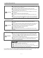
Safety Instructions
(Always read these instructions before using the equipment.)
Do not attempt to install, operate, maintain or inspect the servo amplifier and linear servo motor until you have
read through this Instruction Manual, Installation guide, MR-J3- B Servo Amplifier Instruction Manual and
appended documents carefully and can use the equipment correctly. Do not use the servo amplifier and linear
servo motor until you have a full knowledge of the equipment, safety information and instructions.
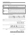
In this Instruction Manual, the safety instruction levels are classified into "WARNING" and "CAUTION".
WARNING
Indicates that incorrect handling may cause hazardous conditions,
resulting in death or severe injury.
CAUTION
Indicates that incorrect handling may cause hazardous conditions,
resulting in medium or slight injury to personnel or may cause physical
damage.
Note that the CAUTION level may lead to a serious consequence according to conditions. Please follow the
instructions of both levels because they are important to personnel safety.
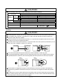
What must not be done and what must be done are indicated by the following diagrammatic symbols.
: Indicates what must not be done. For example, "No Fire" is indicated by
: Indicates what must be done. For example, grounding is indicated by
.
.
In this Instruction Manual, instructions at a lower level than the above, instructions for other functions, and so
on are classified into "POINT".
After reading this installation guide, always keep it accessible to the operator.
A- 1
1. To prevent electric shock, note the following
WARNING
Before wiring or inspection, turn off the power and wait for 15 minutes or more until the charge lamp turns
off. Then, confirm that the voltage between P( ) and N( ) is safe with a voltage tester and others.
Otherwise, an electric shock may occur. In addition, always confirm from the front of the servo amplifier,
whether the charge lamp is off or not.
Connect the servo amplifier and linear servo motor to ground.
Any person who is involved in wiring and inspection should be fully competent to do the work.
Do not attempt to wire the servo amplifier and linear servo motor until they have been installed. Otherwise,
you may get an electric shock.
Operate the switches with dry hand to prevent an electric shock.
The cables should not be damaged, stressed, loaded, or pinched. Otherwise, you may get an electric shock.
During power-on or operation, do not open the front cover of the servo amplifier. You may get an electric
shock.
Do not operate the servo amplifier with the front cover removed. High-voltage terminals and charging area
are exposed and you may get an electric shock.
Except for wiring or periodic inspection, do not remove the front cover even of the servo amplifier if the
power is off. The servo amplifier is charged and you may get an electric shock.
2. To prevent fire, note the following
CAUTION
Install the servo amplifier, servo motor and regenerative resistor on incombustible material. Installing them
directly or close to combustibles will lead to a fire.
Always connect a magnetic contactor (MC) between the main circuit power supply and L1, L2, and L3 of
the servo amplifier, and configure the wiring to be able to shut down the power supply on the side of the
servo amplifier’s power supply. If a magnetic contactor (MC) is not connected, continuous flow of a large
current may cause a fire when the servo amplifier malfunctions.
When a regenerative resistor is used, use an alarm signal to switch main power off. Otherwise, a
regenerative transistor fault or the like may overheat the regenerative resistor, causing a fire.
3. To prevent injury, note the follow
WARNING
The linear servo motor uses a strong magnet on the secondary side. Therefore, not only the linear servo
motor installation operators but also the machine operators must use abundance of caution. For example,
one who uses a medical device like a pacemaker must keep away from the machine.
The permanent magnet on the secondary side makes the magnetic bodies generate suction. Use caution
with accidents so as not to get your hand stuck.
The performance is not guaranteed if the specified servo amplifier and linear servo motor are not
combined. If used with unspecified combination, the servo amplifier or linear servo motor may be
damaged. Depending on the case, it can be out of control and operate unexpectedly, resulting in
extremely dangerous condition.
A- 2
WARNING
Under the packaged condition (cardboard) delivered from our company, the magnet on the secondary
side does not have a serious effect on the outside. Before mounting to the machine, however, magnetic
bodies (including tools) must be kept away from the secondary side (magnetic). The secondary side
(magnetic) can have as double suction power as mounted normally, which may cause a serious injury. To
avoid this, pay full attention to the ambience of workplace.
CAUTION
Only the voltage specified in the Instruction Manual should be applied to each terminal, Otherwise, a
burst, damage, etc. may occur.
Connect the terminals correctly to prevent a burst, damage, etc.
Ensure that polarity ( ,
) is correct. Otherwise, a burst, damage, etc. may occur.
Take safety measures, e.g. provide covers, to prevent accidental contact of hands and parts (cables, etc.)
with the servo amplifier heat sink, regenerative resistor, linear servo motor, etc. since they may be hot
while power is on or for some time after power-off. Their temperatures may be high and you may get burnt
or a parts may damaged.
The linear servo motor installation operators and machine operators must not work wearing electronic
devices (watch, calculator, personal computer, etc.) and magnetic recording media (IC card, magnetic
card, floppy disc, etc.) and must not bring them around a magnetic. The magnetic influence may cause
the operation failure or malfunction.
When the protective function is operated, turn off the power immediately and eliminate its cause, and then
turn it on again. If the linear servo motor is continued operating without eliminating the cause, it may run
unexpectedly and results in a damage and injury.
Securely attach the linear servo motor to the machine. If attach insecurely, it may come off during
operation.
4. Additional instructions
The following instructions should also be fully noted. Incorrect handling may cause a fault, injury, electric shock,
etc.
(1) Transportation and installation
CAUTION
Transport the products correctly according to their weights.
Stacking in excess of the specified number of products is not allowed.
Do not carry the linear servo motor by the cables, shaft or encoder.
Do not hold the front cover to transport the servo amplifier. The servo amplifier may drop.
Install the servo amplifier in a load-bearing place in accordance with the Instruction Manual.
Do not climb or stand on servo equipment. Do not put heavy objects on equipment.
The servo amplifier and linear servo motor must be installed in the specified direction.
Leave specified clearances between the servo amplifier and control enclosure walls or other equipment.
Do not install or operate the servo amplifier and linear servo motor which has been damaged or has any
parts missing.
A- 3
CAUTION
Provide adequate protection to prevent screws and other conductive matter, oil and other combustible
matter from entering the servo amplifier and linear servo motor.
Do not drop or strike servo amplifier or linear servo motor. Isolate from all impact loads.
The protection method of the linear servo motor is IP00. Take necessary measures against dust, oil, etc.
(Refer to section 2.1.2 Installation direction.)
When mounting the secondary side (magnet), use nonmagnetic tools.
Securely attach the linear servo motor to the machine. If attach insecurely, the linear servo motor may
come off during operation.
Do not modify the linear servo motor.
Take safety measures, e.g. provide covers, to prevent accidental access to the linear servo motor during
operation.
The dynamic brake can be applied to the linear servo motor, but the coasting distance becomes longer
when the moving body is heavy or when the speed is high. It may result in crashing into the stroke edge,
which is highly dangerous. Install the anti-crash mechanism such as an air brake or an electric/mechanical
stopper such as a shock absorber to reduce the shock of movable parts. (No linear servo motor with an
electromagnetic brake is available.)
The magnetic suction power acting between the primary side (coil) and the secondary (magnet) is always
acting even when the motor power is not turned on. Because of this, the machine must be designed to be
rigid enough to resist the magnetic suction power and maintain the accuracy.
The running load by friction increases in proportion to the increase of the magnetic suction power, so the
design must be made to decrease as much friction as possible, for example, by mounting guides with high
accuracy.
Do not use for vertical motion applications since magnetic poles cannot be detected with a vertical
application.
Install the linear servo motor the way in which the thrust acts on the gravity center of the movable part.
When the thrust does not act on the gravity center of the movable part, the moment is generated.
Magnetic chips such as iron fragments can be attached to the permanent magnet on the secondary side,
which may cause a malfunction. In the environment like this, take measures against the attachment and
entry of magnetic chips.
When the linear servo motor is operated over a long term under the condition where water for cutting or
lubrication oil is splashed or where oil mist or dew condensation occurs due to supercooling or high
humidity, insulation deterioration or other failures may be caused. Prevent the linear servo motor from oil
and dust with a cover and take measures against dew condensation.
More careful measures against oil and dust must be taken for the linear encoder than the linear servo
motor. For details, please contact the linear encoder manufacturer individually.
The moving direction of the linear servo motor and linear encoder must be matched. Otherwise, the motor
may run unexpectedly.
When two or more secondary side (magnet) is mounted, set the mounting screw accumulative pitch
tolerance within 0.2mm. Clearance may be left between the secondary sides (magnets) depending on
the mounting method and the numbers.
Do not hit the primary side (coil) on the stopper. The primary side may be damaged. Design the machine
so that the stopper is hit on the top table attached to the primary side (coil).
Tap holes on the linear servo motor are for machine installation. Do not use for other purposes.
Do not touch the linear servo motor with wet hands.
For installation, use all screw halls and tap holes prepared on the linear servo motor.
When the equipment has been stored for an extended period of time, consult Mitsubishi.
A- 4
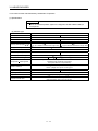
CAUTION
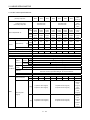
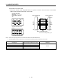
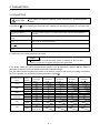
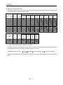
When you keep or use it, please fulfill the following environmental conditions.
Conditions
Environment
Ambient
temperature
Ambient
humidity
Servo amplifier
In
operation
[
[
[
In storage
[
In operation
In storage
Ambience
Altitude
Vibration
Linear servo motor
] 0 to 55 (non-freezing)
0 to 40 (non-freezing)
] 32 to 131 (non-freezing)
32 to 104 (non-freezing)
]
20 to 65 (non-freezing)
15 to 70 (non-freezing)
]
4 to 149 (non-freezing)
5 to 158 (non-freezing)
90%RH or less (non-condensing)
80%RH or less (non-condensing)
90%RH or less (non-condensing)
Indoors (no direct sunlight) Free from corrosive gas, flammable gas, oil mist, dust and dirt
Max. 1000m above sea level
LM-H2 Series
X Y : 49 m/s2
5.9 m/s2 or less
LM-U2 Series
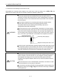
(2) Wiring
CAUTION
Wire the equipment correctly and securely. Otherwise, the linear servo motor may operate unexpectedly.
Do not install a power capacitor, surge absorber or radio noise filter (FR-BIF-(H) option) between the
linear servo motor and servo amplifier.
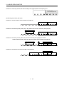
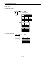
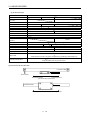
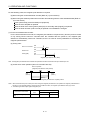
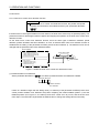
Connect the wires to the correct phase terminals (U, V, W) of the servo amplifier and linear servo motor.
Not doing so may cause unexpected operation.
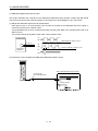
Connect the servo motor power terminal (U, V, W) to the linear servo motor power input terminal (U, V, W)
directly. Do not let a magnetic contactor, etc. intervene.
Servo amplifier
Linear servo motor
U
U
V
V
Linear servo motor
U
U
V
V
M
W
W
Servo amplifier
M
W
W
Do not connect AC power directly to the linear servo motor. Otherwise, a fault may occur.
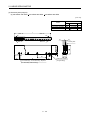
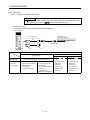
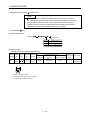
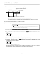
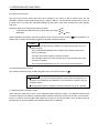
The surge absorbing diode installed on the DC output signal relay of the servo amplifier must be wired in
the specified direction. Otherwise, the forced stop (EM1) and other protective circuits may not operate.
Servo
amplifier
Servo
amplifier
24VDC
DOCOM
DOCOM
DICOM
DICOM
Control
output
signal
Control
output
signal
RA
24VDC
RA
When the cable is not tightened enough to the terminal block (connector), the cable or terminal block
(connector) may generate heat because of the poor contact. Be sure to tighten the cable with specified
torque.
The cables such as power cables deriving from the primary side (coil) cannot stand the long-term flexing
action. Avoid the flexing action by fixing to the movable part, etc. Also, use the cable that stands the longterm flexing action for the wiring to the servo amplifier.
A- 5
(3) Test run adjustment
CAUTION
Before operation, check the parameter settings. Improper settings may cause some machines to perform
unexpected operation.
The parameter settings must not be changed excessively. Operation will be insatiable.
(4) Usage
CAUTION
Provide an external emergency stop circuit to ensure that operation can be stopped and power switched
off immediately.
Any person who is involved in disassembly and repair should be fully competent to do the work.
Before resetting an alarm, make sure that the run signal of the servo amplifier is off to prevent an accident.
A sudden restart is made if an alarm is reset with the run signal on.
Do not modify the equipment.
Use a noise filter, etc. to minimize the influence of electromagnetic interference, which may be caused by
electronic equipment used near the servo amplifier.
Burning or breaking a servo amplifier may cause a toxic gas. Do not burn or break a servo amplifier.
Use the servo amplifier with the specified linear servo motor.
(5) Corrective actions
CAUTION
When it is assumed that a hazardous condition may take place at the occur due to a power failure or a
product fault, use a linear servo motor with electromagnetic brake or an external brake mechanism for the
purpose of prevention.
When any alarm has occurred, eliminate its cause, ensure safety, and deactivate the alarm before
restarting operation.
When power is restored after an instantaneous power failure, keep away from the machine because the
machine may be restarted suddenly (design the machine so that it is secured against hazard if restarted).
(6) Maintenance, inspection and parts replacement
CAUTION
When the linear servo motor is damaged, it must be replaced. Contact Mitsubishi Electric System &
Service Co., Ltd.
With age, the electrolytic capacitor of the servo amplifier will deteriorate. To prevent a secondary accident
due to a fault, it is recommended to replace the electrolytic capacitor every 10 years when used in general
environment.
Please consult our sales representative.
A- 6
(7) Disposal
CAUTION
The linear servo motor uses a strong magnet on the secondary side. Therefore, not only the operators but
also the people around the work place must use abundance of caution when the linear servo motor is
disassembled or discarded. For example, one who uses a medical device like a pacemaker must keep
away from the machine.
The permanent magnet on the secondary side makes the magnetic bodies (primary side [coil] and
secondary side [magnet]) generate suction. Use special caution with the handling of the secondary side
which is demagnetized before/after disassembly.
When the linear servo motor is disassembled or discarded, do not put magnetic bodies (including the
primary side [coil], the other secondary sides [magnet] and tools) close to the secondary side (magnet).
The secondary side (magnetic) can have as double suction power as mounted normally, which may cause
a serious injury. In all cases, pay full attention to the ambience of workplace to avoid this.
CAUTION
A suction power is generated when magnetic bodies (including tools) are put near the permanent magnet
on the secondary side. Be sure to use nonmagnetic tools for the disassembly and disposal of the linear
servo motor or the work around it. These are required for the improvement of workability and safety
ensuring.
The personnel who work for the disassembly or disposal of the linear servo motor or those who are
around the workplace must not work wearing electronic devices (watch, calculator, personal computer,
etc.) and magnetic recording media (IC card, magnetic card, floppy disc, etc.) and must not bring them
around the secondary side (magnet). Magnetic influence may cause the operation failure or malfunction.
The servo amplifier and the primary side (coil) of the linear servo motor must be discarded in accordance
with "About processing of waste".
Since the secondary side (magnet) of the linear servo motor uses the permanent magnet, demagnetize
the entire secondary side (magnet) by heating over 300 (572 ), then discard in accordance with "About
processing of waste".
Do not touch the secondary side after the demagnetization of the secondary side (magnet) by heating
over 300 (572 ) until it becomes cool enough. Otherwise, you may get burnt.
(8) General instruction
To illustrate details, the equipment in the diagrams of this Specifications and Instruction Manual may have
been drawn without covers and safety guards. When the equipment is operated, the covers and safety
guards must be installed as specified. Operation must be performed in accordance with this Specifications
and Instruction Manual.
A- 7
About processing of waste
When you discard servo amplifier, a battery (primary battery), and other option articles, please follow the law of
each country (area).
FOR MAXIMUM SAFETY
These products have been manufactured as a general-purpose part for general industries, and have not
been designed or manufactured to be incorporated in a device or system used in purposes related to
human life.
Before using the products for special purposes such as nuclear power, electric power, aerospace,
medicine, passenger movement vehicles or under water relays, contact Mitsubishi.
These products have been manufactured under strict quality control. However, when installing the product
where major accidents or losses could occur if the product fails, install appropriate backup or failsafe
functions in the system.
EEP-ROM life
The number of write times to the EEP-ROM, which stores parameter settings, etc., is limited to 100,000. If
the total number of the following operations exceeds 100,000, the servo amplifier and/or converter unit may
fail when the EEP-ROM reaches the end of its useful life.
Write to the EEP-ROM due to parameter setting changes
Write to the EEP-ROM due to device changes
Precautions for Choosing the Products
Mitsubishi will not be held liable for damage caused by factors found not to be the cause of Mitsubishi;
machine damage or lost profits caused by faults in the Mitsubishi products; damage, secondary damage,
accident compensation caused by special factors unpredictable by Mitsubishi; damages to products other
than Mitsubishi products; and to other duties.
A- 8
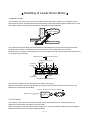
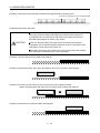
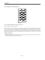
Handling of Linear Servo Motor
1. Magnetic suction
The secondary side of the linear servo motor contains a strong permanent magnet, so a magnetic suction
power (power by which a magnet attracts magnetic bodies) is generated toward magnetic bodies such as iron.
Magnetic suction
This magnet suction is always acting whether the motor power is turned ON/OFF.
Always acting whether
the power is ON/OFF
Magnet face side
Mount (yoke) face side
The magnetic fluxes generating from the permanent magnet disperse in the air from the magnet face side
(facing the primary side), and most of them do not leak to the mount (yoke) side for its structure.
Because of this, a magnetic suction power occurs on the magnet face side of the secondary side and does not
on the mount (yoke) face side.
Magnet face side
Magnetic fluxes disperse.
Magnetic suction occurs.
Magnetic
fluxes
Permanent
magnet
N
S
Mount face side
Mount (yoke)
N
Magnetic fluxes do not
disperse.
Magnetic suction does not occur.
The permanent magnet used for the linear servo motor is very strong.
When an A4-sized iron sheet is fully attracted, the magnetic suction power becomes as high as 2.5t. Use
abundance of caution with the handling.
When an A4-sized iron sheet is fully attracted
Magnetic suction
400[kPa]
A4
(21 29.7cm)
Approx. 2.5t
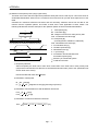
2. For the safety
The magnetic suction power is in inverse proportion to square of the distance to a magnetic body, so it
drastically increases when the distance becomes small.
When mounting the secondary side of the linear side motor, ensure the sufficient distance from the magnetic
bodies around it and securely fix those magnetic bodies.
A- 9
3. Notes on handling
(1) Handling must be done by the engineers who have a full knowledge of this product.
(2) One who uses a medical device like a pacemaker must keep away from the machine and
equipment.
(3) Do not wear metals such as watch, pierced earring, necklace, etc.
(4) Use nonmagnetic tools.
(Example) Explosion-proof beryllium copper alloy safety tools: bealon (NGK Insulators, Ltd.)
(5) Do not put magnetic card, watch, portable phone, etc close to the motor.
(6) Do not add a shock or a stress on the mold part of the product. (Otherwise, the motor may be
damaged.)
(7) Display "Note a strong magnetic." or the like and take action by giving cautions to the
surrounding, etc.
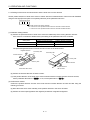
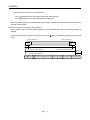
4. Disposal of linear servo motor
(1) The primary side must be discarded as industrial waste.
(2) The secondary side must be discarded as industrial waste after demagnetizing the secondary
side over 300 (572 ).
(3) When the demagnetization is not possible, pack into a box and return to us.
(4) Do not leave the product.
Primary side
Secondary side
After demagnetizing over 300
discard as industrial waste.
Discard as industrial waste.
A - 10
(572
),
COMPLIANCE WITH EC DIRECTIVES
1. WHAT ARE EC DIRECTIVES?
The EC directives were issued to standardize the regulations of the EU countries and ensure smooth
distribution of safety-guaranteed products. In the EU countries, the machinery directive (effective in January,
1995), EMC directive (effective in January, 1996) and low voltage directive (effective in January, 1997) of the
EC directives require that products to be sold should meet their fundamental safety requirements and carry the
CE marks (CE marking). CE marking applies to machines and equipment into which servo amplifiers have
been installed.
(1) EMC directive
The EMC directive applies not to the servo units alone but to servo-incorporated machines and equipment.
This requires the EMC filters to be used with the servo-incorporated machines and equipment to comply
with the EMC directive. For specific EMC directive conforming methods, refer to the EMC Installation
Guidelines (IB(NA)67310).
(2) Low voltage directive
The low voltage directive applies also to servo units alone. Hence, they are designed to comply with the low
voltage directive.
This servo is certified by TUV, third-party assessment organization, to comply with the low voltage directive.
(3) Machine directive
Not being machines, the servo amplifiers need not comply with this directive.
2. PRECAUTIONS FOR COMPLIANCE
(1) Servo amplifiers used
Use the servo amplifiers which comply with the standard model.
Servo amplifier
:MR-J3-10B-RJ004 to MR-J3-15KB-RJ004
MR-J3-22KB4-RJ004
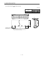
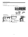
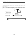
(2) Configuration
The control circuit provide safe separation to the main circuit in the servo amplifier.
Control box
Reinforced
insulating type
No-fuse
breaker
Magnetic
contactor
NFB
MC
24VDC
power
supply
Servo
amplifier
Linear servo motor
(3) Environment
Operate the servo amplifier at or above the contamination level 2 set forth in IEC60664-1. For this purpose,
install the servo amplifier in a control box which is protected against water, oil, carbon, dust, dirt, etc. (IP54).
A - 11
(4) Power supply
(a) This servo amplifier can be supplied from star-connected supply with earthed neutral point of
overvoltage category III set forth in IEC60664-1. However, when using the neutral point of 400V class
for single phase supply, a reinforced insulating transformer is required in the power input section.
(b) When supplying interface power from external, use a 24VDC power supply which has been insulationreinforced in I/O.
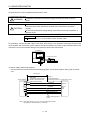
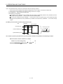
(5) Grounding
(a) To prevent an electric shock, always connect the protective earth (PE) terminals (marked
servo amplifier to the protective earth (PE) of the control box.
) of the
(b) Do not connect two ground cables to the same protective earth (PE) terminal. Always connect the
cables to the terminals one-to-one.
PE terminals
PE terminals
(c) If a leakage current breaker is used to prevent an electric shock, the protective earth (PE) terminals of the
servo amplifier must be connected to the corresponding earth terminals.
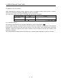
(6) Wiring
The cables to be connected to the terminal block of the servo amplifier must have crimping terminals
provided with insulating tubes to prevent contact with adjacent terminals.
Crimping terminal
Insulating tube
Cable
(7) Auxiliary equipment and options
(a) The no-fuse breaker and magnetic contactor used should be the EN or IEC standard-compliant
products of the models described in MR-J3- B Servo Amplifier Instruction Manual section 11.12.
Use a type B (Note) breaker. When it is not used, provide insulation between the servo amplifier and
other device by double insulation or reinforced insulation, or install a transformer between the main
power supply and servo amplifier.
Note. Type A: AC and pulse detectable
Type B: Both AC and DC detectable
(b) The sizes of the cables described in section 4.2 meet the following requirements. To meet the other
requirements, follow Table 5 and Appendix C in EN60204-1.
Ambient temperature: 40 (104) [°C (°F)]
Sheath: PVC (polyvinyl chloride)
Installed on wall surface or open table tray
(c) Use the EMC filter for noise reduction.
A - 12
(8) Performing EMC tests
When EMC tests are run on a machine/device into which the servo amplifier has been installed, it must
conform to the electromagnetic compatibility (immunity/emission) standards after it has satisfied the
operating environment/electrical equipment specifications.
For the other EMC directive guidelines on the servo amplifier, refer to the EMC Installation Guidelines
(IB(NA)67310).
<<About the manuals>>
This Instruction Manual and the MR-J3- B Servo Amplifier Instruction Manual are required if you use the
linear servo for the first time. Always purchase them and use the linear servo safely.
Relevant manuals
Manual name
Manual No.
MELSERVO-J3 Series Instruction and Cautions for Safe Use of AC Servos
IB(NA)0300077
MR-J3- B Servo Amplifier Instruction Manual
SH(NA)030051
EMC Installation Guidelines
IB(NA)67310
<<About the wires used for wiring>>
Wiring wires mentioned in this instruction manual are selected based on the ambient temperature of 40°C
(104 ).
A - 13
MEMO
A - 14
CONTENTS
1. FUNCTIONS AND CONFIGURATION
1 - 1 to 1 -20
1.1 Introduction............................................................................................................................................... 1 - 1
1.2 Servo amplifier standard specifications................................................................................................... 1 - 3
1.3 Function list .............................................................................................................................................. 1 - 4
1.4 Model code definition ............................................................................................................................... 1 - 5
1.5 Combinations of Servo Amplifiers and Linear Servo Motors.................................................................. 1 - 6
1.6 Parts identification.................................................................................................................................... 1 - 8
1.7 Configuration including auxiliary equipment .......................................................................................... 1 -14
2. LINEAR SERVO MOTOR
2 - 1 to 2 -48
2.1 Handling ................................................................................................................................................... 2 - 1
2.1.1 General instructions .......................................................................................................................... 2 - 1
2.1.2 Instructions on design ....................................................................................................................... 2 - 2
2.1.3 Instructions on installation operation ................................................................................................ 2 - 3
2.1.4 Instructions on storage...................................................................................................................... 2 - 4
2.2 Inspection items ....................................................................................................................................... 2 - 4
2.2.1 Inspections on primary side (coil) ..................................................................................................... 2 - 5
2.2.2 Inspections on secondary side (magnet).......................................................................................... 2 - 6
2.2.3 Inspections of linear encoder ............................................................................................................ 2 - 6
2.3 Replacement of linear servo motor on absolute position detection system........................................... 2 - 7
2.3.1 Replacement of primary side (coil) or secondary side (magnet) ..................................................... 2 - 7
2.3.2 Replacement of linear encoder......................................................................................................... 2 - 7
2.4 Instructions for discarding the linear servo motor ................................................................................... 2 - 8
2.5 LM-H2 series ............................................................................................................................................ 2 - 9
2.5.1 Model code definition ........................................................................................................................ 2 - 9
2.5.2 LM-H2 series specification list ......................................................................................................... 2 -11
2.5.3 Thrust characteristics ....................................................................................................................... 2 -13
2.5.4 Installation......................................................................................................................................... 2 -14
2.5.5 Outline drawings............................................................................................................................... 2 -17
2.5.6 Connection of servo amplifier and linear servo motor .................................................................... 2 -20
2.6 LM-U2 series ........................................................................................................................................... 2 -21
2.6.1 Model code definition ....................................................................................................................... 2 -21
2.6.2 LM-U2 series specification list ......................................................................................................... 2 -23
2.6.3 Thrust characteristics ....................................................................................................................... 2 -25
2.6.4 Installation......................................................................................................................................... 2 -26
2.6.5 Outline drawings............................................................................................................................... 2 -29
2.6.6 Connection of servo amplifier and linear servo motor .................................................................... 2 -35
2.7 LM-F series.............................................................................................................................................. 2 -36
2.7.1 Model code definition ....................................................................................................................... 2 -36
2.7.2 LM-F series specification list............................................................................................................ 2 -37
2.7.3 Thrust characteristics ....................................................................................................................... 2 -39
2.7.4 Installation......................................................................................................................................... 2 -40
2.7.5 Outline drawings............................................................................................................................... 2 -43
2.7.6 Connection of servo amplifier and linear servo motor .................................................................... 2 -47
1
3. LINEAR ENCODER
3 - 1 to 3 -32
3.1 Compatible linear encoder list ................................................................................................................. 3 - 1
3.2 Mitsubishi serial interface compatible linear encoder ............................................................................. 3 - 2
3.2.1 Mitutoyo Corporation make linear scales (Absolute type) ............................................................... 3 - 2
3.2.2 Linear encoder manufactured by Heidenhain Corporation............................................................. 3 -11
3.2.3 Linear encoder manufactured by Sony Manufacturing Systems Corporation (Incremental type) 3 -19
3.2.4 Linear encoder manufactured by Renishaw Inc. (Incremental type).............................................. 3 -24
3.3 ABZ-phase differential output encoder................................................................................................... 3 -27
3.4 Mitsubishi optional cable connector sets ............................................................................................. 3 -30
3.4.1 MR-EKCBL M-H ............................................................................................................................ 3 -30
3.4.2 MR-ECNM ........................................................................................................................................ 3 -32
3.4.3 MR-J3CN2........................................................................................................................................ 3 -32
4. SIGNALS AND WIRING
4 - 1 to 4 -14
4.1 Precautions on this chapter ..................................................................................................................... 4 - 2
4.2 Power supply system circuit connection example .................................................................................. 4 - 2
4.2.1 Selection example of wires ............................................................................................................... 4 - 3
4.2.2 Connection example ......................................................................................................................... 4 - 5
4.3 I/O signal connection example ............................................................................................................... 4 -10
4.4 Connectors and signal arrangements .................................................................................................... 4 -12
4.5 Internal connection diagram ................................................................................................................... 4 -13
5. OPERATION AND FUNCTIONS
5 - 1 to 5 -28
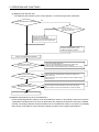
5.1 Startup ...................................................................................................................................................... 5 - 1
5.1.1 Startup procedure.............................................................................................................................. 5 - 1
5.1.2 Settings of the linear encoder direction and the linear servo motor direction ................................. 5 - 2
5.1.3 Setting of the linear encoder resolution............................................................................................ 5 - 3
5.2 Settings of the magnetic pole detection and the magnetic pole detection voltage level ....................... 5 - 4
5.2.1 Preparation for the magnetic pole detection .................................................................................... 5 - 4
5.2.2 Magnetic pole detection .................................................................................................................... 5 - 4
5.2.3 Setting of the magnetic pole detection voltage level........................................................................ 5 - 8
5.2.4 Magnetic pole detection method using MR Configurator................................................................. 5 - 9
5.2.5 Magnetic pole detection at the replacement of servo amplifier ...................................................... 5 -10
5.2.6 Magnetic pole detection under the specified condition ................................................................... 5 -12
5.3 Home position return............................................................................................................................... 5 -14
5.3.1 Incremental linear encoder .............................................................................................................. 5 -14
5.3.2 Absolute position linear encoder...................................................................................................... 5 -16
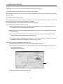
5.4 Test operation mode in MR Configurator ............................................................................................... 5 -17
5.5 Operation from the controller .................................................................................................................. 5 -19
5.5.1 Operation method............................................................................................................................. 5 -19
5.5.2 Servo system controller setting........................................................................................................ 5 -20
5.6 Functions ................................................................................................................................................. 5 -25
5.6.1 Linear servo control error detection function................................................................................... 5 -25
5.6.2 Auto tuning function ......................................................................................................................... 5 -27
5.6.3 Machine analyzer function ............................................................................................................... 5 -27
5.7 Absolute position detection system ........................................................................................................ 5 -27
2
6. PARAMETERS
6 - 1 to 6 -18
6.1 Parameter write inhibit (Parameter No.PA19)......................................................................................... 6 - 1
).................................................................................................... 6 - 2
6.2 Basic setting parameters (No.PA
6.2.1 Parameter list .................................................................................................................................... 6 - 2
6.2.2 List of details...................................................................................................................................... 6 - 3
6.3 Gain/Filter parameters (No.PB
) ....................................................................................................... 6 - 6
6.3.1 Parameter list .................................................................................................................................... 6 - 6
6.3.2 List of details...................................................................................................................................... 6 - 7
6.4 Extension setting parameters (No.PC
) ............................................................................................ 6 - 8
6.4.1 Parameter list .................................................................................................................................... 6 - 8
6.4.2 List of details...................................................................................................................................... 6 - 9
6.4.3 Analog monitor ................................................................................................................................. 6 -11
6.5 I/O setting parameters (No.PD
) ...................................................................................................... 6 -13
6.5.1 Parameter list ................................................................................................................................... 6 -13
6.5.2 List of details..................................................................................................................................... 6 -14
6.6 Special setting parameters (No.PS
) ............................................................................................... 6 -15
6.6.1 Parameter list ................................................................................................................................... 6 -15
6.6.2 List of details..................................................................................................................................... 6 -16
7. TROUBLESHOOTING
7 - 1 to 7 - 8
7.1 Alarms and warning list............................................................................................................................ 7 - 1
7.2 Remedies for alarms................................................................................................................................ 7 - 2
7.3 Remedies for warnings ............................................................................................................................ 7 - 7
7.4 Detailed explanation of linear encoder error 1 (2A) ................................................................................ 7 - 8
8. SERVO AMPLIFIER OUTLINE DRAWINGS
8 - 1 to 8 - 8
9. CHARACTERISTICS
9 - 1 to 9 - 2
9.1 Overload protection characteristics ......................................................................................................... 9 - 1
9.2 Dynamic brake characteristics................................................................................................................. 9 - 2
APPENDIX
App.- 1 to App.-11
App. 1 Parameter list..................................................................................................................................App.- 1
App. 2 Signal layout recording paper ........................................................................................................App.- 3
App. 3 Capacity selection of linear servo motor........................................................................................App.- 3
App. 4 Change of connector sets to the RoHS compatible products.......................................................App.- 8
App. 5 MR-J3-200B-RJ004 servo amplifiers manufactured before March 2008.....................................App.- 9
3
MEMO
4
1. FUNCTIONS AND CONFIGURATION
1. FUNCTIONS AND CONFIGURATION
1.1 Introduction
In fields of semiconductor and liquid crystal related equipment, installed machine, etc. with strong demands
for high accuracy, high-speed and high efficiency, the system using the linear servo motor for drive shaft is
increasing. Since the linear servo system can obtain the characteristics of the high-speed and the high
acceleration/deceleration greater than the ball screw drive system, and does not have a ball screw wear
which is a weak point in the ball screw drive system, it can extend the life of the equipments. In addition, a
response error does not occur and so the high accuracy system can be established.
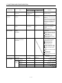
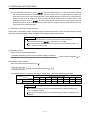
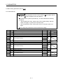
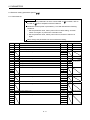
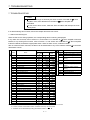
The following shows the differences between the linear servo motor and the rotating servo motor.
1- 1
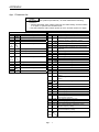
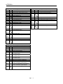
1. FUNCTIONS AND CONFIGURATION
Classification
Item
External I/O signal
Stroke limit input signal
(FLS, RLS)
Motor pole
adjustment
Magnetic pole detection
operation
Differences
Linear servo motor
Rotating servo motor
(MR-J3- B-RJ004)
(MR-J3- B)
Required (when
magnetic pole is
detected)
Required
Automatically turns ON in the
parameter setting.
Unit: mm/s
Not required (adjusted Automatically executed at the
at shipment)
first servo-on after turning the
power on.
For the absolute position linear
encoder, the magnetic polarity
detection can be made invalid
in the setting of parameter
No.PS01.
(Refer to section 5.2.2 (2).)
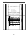
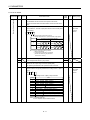
Servo motor 1 rotation The home position pitch can be
unit
changed in the parameter
settings.
(Refer to section 5.3)
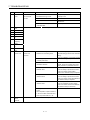
Required
The following alarm/warning is
not detected.
Absolute position erase (25)
Battery cable disconnection
warning (92)
Battery warning (9F)
Absolute position counter
warning (E3)
Alarm/warning which is added
or the contents is changed
Encoder error1 (16)
Encoder error2 (20)
Initial magnetic pole
detection error (27)
Linear encoder error2 (28)
Linear encoder error1 (2A)
Linear servo control error
(42)
Linear servo motor overheat
(46)
Overload1 (50)
Overload2 (51)
Linear servo motor overheat
warning (E2)
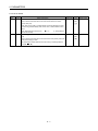
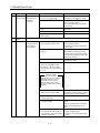
Load inertia moment
ratio
Unit: r/min
Available
Available
Not available
Available
Not available
Available
Available
Available
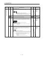
Home position return Home position reference
position
1048576 pluses unit
(Initial value)
Absolute position
detection system
Battery for absolute position
encoder
(MR-J3BAT)
Not required
Alarm/warning
Alarm/warning designed
exclusively for the linear
servo motor
Addition
Auto tuning
Load inertia moment ratio (J)
Load mass ratio
MR Configurator 221 Motor speed
(Ver. B3 or later)
(data display, setting)
Test
Positioning
operation operation
function Motor-less
operation
JOG operation
Program operation
Not required
Remarks
1- 2
1. FUNCTIONS AND CONFIGURATION
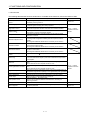
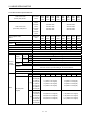
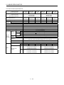
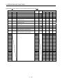
1.2 Servo amplifier standard specifications
Servo amplifier
MR-J3- -RJ004U*** 10B
20B
40B
60B
70B 100B 200B 350B 500B 700B 11KB 15KB
22KB4
Power supply
Item
Voltage/frequency
3-phase or 1-phase 200 to
230VAC, 50/60Hz
3-phase 200 to 230VAC, 50/60Hz
3-phase 380 to
480VAC, 50/60Hz
Permissible voltage fluctuation
3-phase or 1-phase 200 to
230VAC: 170 to 253VAC
3-phase 170 to 253VAC
3-phase 323 to
528VAC
Permissible frequency
fluctuation
Within 5%
Power supply capacity
Refer to the specification list of the linear servo motor.
Inrush current
Refer to section 10.5 "MR-J3- B Servo Amplifier Instruction Manual"
Voltage,
frequency
Control circuit
power supply
1-phase 200 to 230VAC, 50/60Hz
1-phase 380 to
480VAC, 50/60Hz
1-phase 170 to 253VAC
1-phase 323 to
528VAC
Permissible
voltage
fluctuation
Permissible
frequency
fluctuation
Within 5%
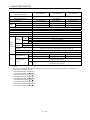
Input
30W
45W
Refer to section 10.5 "MR-J3- B Servo Amplifier Instruction Manual"
Inrush current
Voltage
24VDC 10%
Interface power
Power supply
supply
capacity
(Note 1) 150mA
Control System
Sine-wave PWM control, current control system
Dynamic brake
Built-in
Protective functions
Structure
Environment
Ambient
temperature
Ambient
humidity
External option
Overcurrent shut-off, regenerative overvoltage shut-off, overload shut-off (electronic thermal
relay), servo motor overheat protection, encoder error protection, regenerative error protection,
undervoltage, instantaneous power failure protection, overspeed protection, excessive error
protection
Self-cooled, open (IP00)
In operation
In storage
Force-cooling, open (IP00)
[ ]
(Note 2) 0 to 55 (non-freezing)
[ ]
(Note 2) 32 to 131 (non-freezing)
[ ]
20 to 65 (non-freezing)
[ ]
4 to 149 (non-freezing)
In operation
90%RH or less (non-condensing)
In storage
Ambient
Indoors (no direct sunlight)
Free from corrosive gas, flammable gas, oil mist, dust and dirt
Altitude
Max. 1000m above sea level
5.9 [m/s2] or less
Vibration
Mass
[kg]
0.8
0.8
1.0
1.0
1.4
1.4
2.1
[lb]
1.8
1.8
2.2
2.2
3.1
3.1
4.63 5.07 10.1 13.7 39.7 39.7
2.3
4.6
6.2
18
18
19
41.9
Note 1. 150mA is the value applicable when all I/O signals are used. The current capacity can be decreased by reducing the number of
I/O points.
2. When closely mounting the servo amplifier of MR-J3-350B-RJ004U*** or less, operate them at the ambient temperatures of 0 to
45 (32 to 113 ) or at 75% or smaller effective load ratio.
1- 3
1. FUNCTIONS AND CONFIGURATION
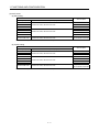
1.3 Function list
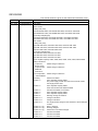
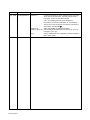
The following table lists the functions of this servo. For details of the functions, refer to the reference field.
Function
Absolute position detection
system
Gain changing function
Advanced vibration
suppression control
Adaptive filter
Low-pass filter
Machine analyzer function
Machine simulation
Gain search function
Slight vibration suppression
control
Auto tuning
Brake unit
Power regenerative converter
Regenerative option
Alarm history clear
Output signal (DO)
forced output
Test operation mode
Analog monitor output
MR Configurator
Description
Merely setting a home position once makes home position return
unnecessary at every power-on.
You can switch between gains during rotation and gains during stop or use
an external signal to change gains during operation.
This function suppresses vibration at the arm end or residual vibration.
Servo amplifier detects mechanical resonance and sets filter characteristics
automatically to suppress mechanical vibration.
Suppresses high-frequency resonance which occurs as servo system
response is increased.
Analyzes the frequency characteristic of the mechanical system by simply
connecting a MR Configurator-installed personal computer and servo
amplifier.
MR Configurator MRZJW3-SETUP221E is necessary for this function.
Can simulate machine motions on a personal computer screen on the basis
of the machine analyzer results.
MR Configurator MRZJW3-SETUP221E is necessary for this function.
Personal computer changes gains automatically and searches for overshootfree gains in a short time.
MR Configurator MRZJW3-SETUP221E is necessary for this function.
Reference
Section 5.7
MR-J3- B Servo
Amplifier Instruction
Manual
Suppresses vibration of 1 pulse produced at a linear servo motor stop.
Automatically adjusts the gain to optimum value if load applied to the linear
servo motor shaft varies. Higher in performance than MR-J2-Super series
servo amplifier.
Used when the regenerative option cannot provide enough regenerative
power.
Can be used with the servo amplifier of 5kW or more.
Used when the regenerative option cannot provide enough regenerative
power.
Can be used with the servo amplifier of 5kW or more.
Used when the built-in regenerative resistor of the servo amplifier does not
have sufficient regenerative capability for the regenerative power generated.
Alarm history is cleared.
Output signal can be forced on/off independently of the servo status.
Use this function for output signal wiring check, etc.
Positioning operation DO forced output.
However, MR Configurator MRZJW3-SETUP221E is necessary for
positioning operation.
Servo status is output in terms of voltage in real time.
Using a personal computer, parameter setting, test operation, status display,
etc. can be performed.
1- 4
MR-J3- B Servo
Amplifier Instruction
Manual
Parameter No.PC09
Section 5.4
1. FUNCTIONS AND CONFIGURATION
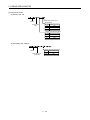
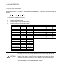
1.4 Model code definition
(1) Rating plate
MITSUBISHI
AC SERVO
Model
Capacity
MODELMR-J3-10B-RJ004
POWER : 100W
INPUT : 0.9A 3PH+1PH200-230V 50Hz
3PH+1PH200-230V 60Hz
1.3A 1PH 200-230V 50/60Hz
OUTPUT : 170V 0-360Hz 1.1A
SERIAL : A34230001
Applicable power supply
Rated output current
Serial number
PASSED
MITSUBISHI ELECTRIC CORPORATION
MADE IN JAPAN
(2) Model
(a) 200V class
Series
Linear servo motor
compatible symbol
Refer to section 1.5.
Linear servo motor compatible
SSCNET
compatible
Rated output
Symbol Rated output [kW]
10
0.1
20
0.2
40
0.4
60
0.6
70
0.75
100
1
200
2
350
3.5
500
5
700
7
11K
11
15K
15
(b) 400V class
Series
Linear servo motor
compatible symbol
Refer to section 1.5.
Linear servo motor compatible
400V class
SSCNET
compatible
Rated output: 22kW
1- 5
1. FUNCTIONS AND CONFIGURATION
1.5 Combinations of Servo Amplifiers and Linear Servo Motors
POINT
Check the linear servo compatible symbols (U ) and use the servo amplifier
and linear servo motor with correct combination. When used with incorrect
combination, the servo amplifier or linear servo motor may fail.
(1) LM-H2 series
Linear servo motor
Primary side (coil)
LM-H2P1A-06M-4SS0
Secondary side (magnet)
LM-H2S10-288-4SS0, LM-H2S10-384-4SS0, LM-H2S10-480-4SS0
LM-H2S10-768-4SS0
Servo amplifier
MR-J3-40B-RJ004U500
LM-H2P2A-12M-1SS0
MR-J3-40B-RJ004U501
LM-H2P2B-24M-1SS0 LM-H2S20-288-1SS0, LM-H2S20-384-1SS0, LM-H2S20-480-1SS0
LM-H2P2C-36M-1SS0 LM-H2S20-768-1SS0
MR-J3-70B-RJ004U502
LM-H2P2D-48M-1SS0
MR-J3-200B-RJ004U504
LM-H2P3A-24M-1SS0
MR-J3-70B-RJ004U505
LM-H2P3B-48M-1SS0 LM-H2S30-288-1SS0, LM-H2S30-384-1SS0, LM-H2S30-480-1SS0
LM-H2P3C-72M-1SS0 LM-H2S30-768-1SS0
MR-J3-200B-RJ004U506
LM-H2P3D-96M-1SS0
MR-J3-500B-RJ004U508
MR-J3-200B-RJ004U503
MR-J3-350B-RJ004U507
(2) LM-U2 series
Linear servo motor
Primary side (coil)
Secondary side (magnet)
Servo amplifier
LM-U2PAB-05M-0SS0
MR-J3-20B-RJ004U512
LM-U2PAD-10M-0SS0 LM-U2SA0-240-0SS0, LM-U2SA0-300-0SS0, LM-U2SA0-420-0SS0
MR-J3-40B-RJ004U513
LM-U2PAF-15M-0SS0
MR-J3-40B-RJ004U514
LM-U2PBB-07M-1SS0
MR-J3-20B-RJ004U515
LM-U2PBD-15M-1SS0 LM-U2SB0-240-1SS0, LM-U2SB0-300-1SS0, LM-U2SB0-420-1SS0
MR-J3-60B-RJ004U516
LM-U2PBF-22M-1SS0
MR-J3-70B-RJ004U517
LM-U2P2B-40M-2SS0
MR-J3-200B-RJ004U509
LM-U2P2C-60M-2SS0 LM-U2S20-300-2SS0, LM-U2S20-480-2SS0
MR-J3-350B-RJ004U510
LM-U2P2D-80M-2SS0
MR-J3-500B-RJ004U511
1- 6
1. FUNCTIONS AND CONFIGURATION
(3) LM-F series
(a) Self-cooling
Linear servo motor
Primary side (coil)
Secondary side (magnet)
LM-FP2B-06M-1SS0
LM-FP2D-12M-1SS0
Servo amplifier
MR-J3-200B-RJ004U518
LM-FS20-480-1SS0, LM-FS20-576-1SS0
MR-J3-500B-RJ004U520
LM-FP2F-18M-1SS0
MR-J3-700B-RJ004U522
LM-FP4B-12M-1SS0
MR-J3-500B-RJ004U524
LM-FP4D-24M-1SS0
LM-FP4F-36M-1SS0
LM-FS40-480-1SS0, LM-FS40-576-1SS0
LM-FP4H-48M-1SS0
LM-FP5H-60M-1SS0
MR-J3-700B-RJ004U526
MR-J3-11KB-RJ004U528
MR-J3-15KB-RJ004U530
LM-FS50-480-1SS0, LM-FS50-576-1SS0
(Note)
MR-J3-22KB4-RJ004U532
Note. The servo amplifier is 400V class. A 200V class servo amplifier cannot be used.
(b) Liquid-cooling
Linear servo motor
Primary side (coil)
Secondary side (magnet)
LM-FP2B-06M-1SS0
LM-FP2D-12M-1SS0
Servo amplifier
MR-J3-200B-RJ004U519
LM-FS20-480-1SS0, LM-FS20-576-1SS0
MR-J3-500B-RJ004U521
LM-FP2F-18M-1SS0
MR-J3-700B-RJ004U523
LM-FP4B-12M-1SS0
MR-J3-500B-RJ004U525
LM-FP4D-24M-1SS0
LM-FP4F-36M-1SS0
LM-FS40-480-1SS0, LM-FS40-576-1SS0
LM-FP4H-48M-1SS0
LM-FP5H-60M-1SS0
MR-J3-700B-RJ004U527
MR-J3-11KB-RJ004U529
MR-J3-15KB-RJ004U531
LM-FS50-480-1SS0, LM-FS50-576-1SS0
Note. The servo amplifier is 400V class. A 200V class servo amplifier cannot be used.
1- 7
(Note)
MR-J3-22KB4-RJ004U533
1. FUNCTIONS AND CONFIGURATION
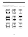
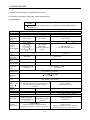
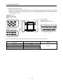
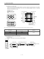
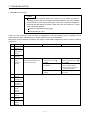
1.6 Parts identification
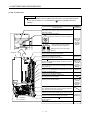
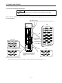
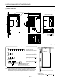
(1) MR-J3-100B-RJ004 or less
Name/Application
Detailed
explanation
3456
0
F 1
2
F01
SW1
TEST
SW2
ON 4E
1
B CDE
B CDE
2
A
789
Rotary axis setting switch (SW1)
SW1
Used to set the axis No. of servo amplifier.
789
A
34 56
Display
The 3-digit, seven-segment LED shows the servo status
and alarm number.
Test operation select switch (SW2-1)
Used to perform the test operation
mode by using MR Configurator.
2
SW2
1
2
Refer to the
MR-J3- B
Servo
Amplifier
Instruction
Manual.
Spare (Be sure to set to the "Down"
position).
USB communication connector (CN5)
Used to connect the personal computer.
Fixed part
(2 places)
Main circuit power supply connector (CNP1)
Used to connect the input power supply.
Section 4.2
I/O signal connector (CN3)
Used to connect digital I/O signals.
More over an analog monitor is output.
Section 4.3
Control circuit connector (CNP2)
Connect the control circuit power supply/regenerative
option.
Section 4.2
SSCNET cable connector (CN1A)
Used to connect the servo system controller or the front
axis servo amplifier.
Refer to the
MR-J3- B
Servo
Amplifier
SSCNET cable connector (CN1B)
Used to connect the rear axis servo amplifier. For the final Instruction
Manual.
axis, puts a cap.
Servo motor power supply connector (CNP3)
Used to connect the servo motor.
Chapter 2
Section 4.2
Connector for thermistor (CN2)
Used to connect the thermistor of the linear servo motor.
Chapter 2
Encoder connector (CN2L)
Used to connect the linear encoder.
Chapter 3
Connector for manufacturer setting (CN4)
Not used for this servo amplifier.
Charge lamp
Lit to indicate that the main circuit is charged. While this
lamp is lit, do not reconnect the cables.
Rating plate
Protective earth (PE) terminal (
Ground terminal.
1- 8
Section 1.4
)
Section 4.2
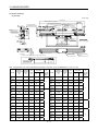
1. FUNCTIONS AND CONFIGURATION
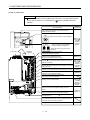
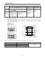
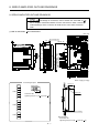
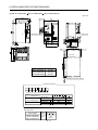
(2) MR-J3-200B-RJ004
Name/Application
Detailed
explanation
Display
The 3-digit, seven-segment LED shows the servo
status and alarm number.
0
F 1
3456
2
3456
F01
2
B CD E
B CD E
789
A
SW1
TEST
SW2
A
Rotary axis setting switch (SW1)
SW1
Used to set the axis No. of servo amplifier.
789
Test operation select switch (SW2-1)
Used to perform the test operation
mode by using MR Configurator.
ON 4E
1
SW2
2
1
2
Spare (Be sure to set to the "Down"
position).
Main circuit power supply connector (CNP1)
Connect the input power supply.
USB communication connector (CN5)
Used to connect the personal computer.
(Note)
Refer to the
MR-J3- B
Servo
Amplifier
Instruction
Manual.
Section 4.2
Refer to the
MR-J3- B
Servo
Amplifier
Instruction
Manual.
I/O signal connector (CN3)
Used to connect digital I/O signals.
More over an analog monitor is output.
Section 4.3
Control circuit connector (CNP2)
Connect the control circuit power supply/regenerative
option.
Section 4.2
SSCNET cable connector (CN1A)
Used to connect the servo system controller or the front
axis servo amplifier.
Refer to the
MR-J3- B
Servo
Amplifier
SSCNET cable connector (CN1B)
Used to connect the rear axis servo amplifier. For the final Instruction
Manual.
axis, puts a cap.
Connector for thermistor (CN2)
Used to connect the thermistor of the linear servo motor.
Chapter 2
Encoder connector (CN2L)
Used to connect the linear encoder.
Chapter 3
Battery connector (CN4)
Used to connect the battery for absolute position data
backup.
Servo motor power connector (CNP3)
Connect the servo motor.
Chapter 2
Section 4.2
Charge lamp
Lit to indicate that the main circuit is charged. While this
lamp is lit, do not reconnect the cables.
Cooling Fan
Fixed part
(3 places)
Protective earth (PE) terminal (
Ground terminal.
Rating plate
)
Section 4.2
Section 1.4
Note. Connectors (CNP1, CNP2, and CNP3) and appearance of MR-J3-200B-RJ004 servo amplifier have been changed from April
2008 production. For existing servo amplifier, refer to appendix 5.
1- 9
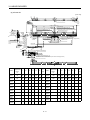
1. FUNCTIONS AND CONFIGURATION
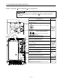
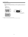
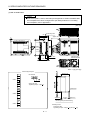
(3) MR-J3-350B-RJ004
Name/Application
Detailed
explanation
34 56
0
F 1
2
F01
SW1
TEST
SW2
ON 4E
1
B CDE
B CDE
2
A
789
Rotary axis setting switch (SW1)
SW1
Used to set the axis No. of servo amplifier.
789
A
3456
Display
The 3-digit, seven-segment LED shows the servo status
and alarm number.
Test operation select switch (SW2-1)
Used to perform the test operation
mode by using MR Configurator.
2
SW2
1
2
Refer to the
MR-J3- B
Servo
Amplifier
Instruction
Manual.
Spare (Be sure to set to the "Down"
position).
USB communication connector (CN5)
Used to connect the personal computer.
Main circuit power supply connector (CNP1)
Used to connect the input power supply.
Section 4.2
I/O signal connector (CN3)
Used to connect digital I/O signals.
More over an analog monitor is output.
Section 4.3
SSCNET cable connector (CN1A)
Used to connect the servo system controller or the front
axis servo amplifier.
Refer to the
MR-J3- B
Servo
Amplifier
SSCNET cable connector (CN1B)
Used to connect the rear axis servo amplifier. For the final Instruction
Manual.
axis, puts a cap.
Servo motor power supply connector (CNP3)
Used to connect the servo motor.
Chapter 2
Section 4.2
Connector for thermistor (CN2)
Used to connect the thermistor of the linear servo motor.
Chapter 2
Encoder connector (CN2L)
Used to connect the linear encoder.
Chapter 3
Connector for manufacturer setting (CN4)
Not used for this servo amplifier.
Control circuit connector (CNP2)
Connect the control circuit power supply/regenerative
option.
Section 4.2
Charge lamp
Lit to indicate that the main circuit is charged. While this
lamp is lit, do not reconnect the cables.
Rating plate
Cooling fan
Fixed part
(3 places)
Protective earth (PE) terminal (
Ground terminal.
1 - 10
Section 1.4
)
Section 4.2
1. FUNCTIONS AND CONFIGURATION
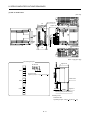
(4) MR-J3-500B-RJ004
POINT
The servo amplifier is shown without the front cover. For removal of the front
cover, refer to section 1.7.2 of the MR-J3- B Servo Amplifier Instruction
Manual.
Name/Application
Detailed
explanation
Display
The 3-digit, seven-segment LED shows the servo status
and alarm number.
0
F 1
3456
2
BCDE
2
F01
A
SW1
TEST
SW2
789
ON 4E
1
BCDE
3456
A
Rotary axis setting switch (SW1)
SW1
Used to set the axis No. of servo amplifier.
789
Test operation select switch (SW2-1)
Used to perform the test operation
mode by using MR Configurator.
SW2
2
1
2
Refer to the
MR-J3- B
Servo
Amplifier
Instruction
Manual.
Spare (Be sure to set to the "Down"
position).
USB communication connector (CN5)
Used to connect the personal computer.
Cooling fan
I/O signal connector (CN3)
Used to connect digital I/O signals.
More over an analog monitor is output.
Section 4.3
SSCNET cable connector (CN1A)
Used to connect the servo system controller or the front
axis servo amplifier.
Refer to the
MR-J3- B
Servo
Amplifier
SSCNET cable connector (CN1B)
Used to connect the rear axis servo amplifier. For the final Instruction
Manual.
axis, puts a cap.
Connector for thermistor (CN2)
Used to connect the thermistor of the linear servo motor.
Chapter 2
Encoder connector (CN2L)
Used to connect the linear encoder.
Chapter 3
Connector for manufacturer setting (CN4)
Not used for this servo amplifier.
DC reactor terminal block (TE3)
Used to connect the DC reactor.
Refer to the
MR-J3- B
Servo
Amplifier
Instruction
Manual.
Charge lamp
Lit to indicate that the main circuit is charged. While this
lamp is lit, do not reconnect the cables.
Main circuit terminal block (TE1)
Used to connect the input power supply and servo motor.
Control circuit terminal block (TE2)
Used to connect the control circuit power supply.
Fixed part
(4 places)
Protective earth (PE) terminal (
Ground terminal.
Rating plate
1 - 11
Chapter 2
Section 4.2
)
Section 1.4
1. FUNCTIONS AND CONFIGURATION
(5) MR-J3-700B-RJ004
POINT
The servo amplifier is shown without the front cover. For removal of the front
cover, refer to section 1.7.2 of the MR-J3- B Servo Amplifier Instruction
Manual.
Name/Application
Detailed
explanation
Display
The 3-digit, seven-segment LED shows the servo
status and alarm number.
3456
2
3 456
F01
0
F 1
2
B CDE
B CD E
SW1
TEST
SW2
A
789
A
Rotary axis setting switch (SW1)
SW1
Used to set the axis No. of servo amplifier.
789
ON 4E
1
1
Cooling fan
Test operation select switch (SW2-1)
Used to perform the test operation
mode by using MR Configurator.
SW2
2
Fixed part
(4 places)
2
Refer to the
MR-J3- B
Servo
Amplifier
Instruction
Manual.
Spare (Be sure to set to the "Down"
position).
USB communication connector (CN5)
Connect the personal computer.
I/O signal connector (CN3)
Used to connect digital I/O signals.
More over an analog monitor is output.
Section 4.3
SSCNET cable connector (CN1A)
Used to connect the servo system controller or the front
axis servo amplifier.
Refer to the
MR-J3- B
Servo
Amplifier
SSCNET cable connector (CN1B)
Used to connect the rear axis servo amplifier. For the final Instruction
Manual.
axis, puts a cap.
Connector for thermistor (CN2)
Used to connect the thermistor of the linear servo motor.
Chapter 2
Encoder connector (CN2L)
Used to connect the linear encoder.
Chapter 3
Connector for manufacturer setting (CN4)
Not used for this servo amplifier.
Refer to the
MR-J3- B
Servo
Amplifier
Instruction
Manual.
DC reactor terminal block (TE3)
Used to connect the DC reactor.
Main circuit terminal block (TE1)
Used to connect the input power supply and servo
motor.
Control circuit terminal block (TE2)
Used to connect the control circuit power supply.
Protective earth (PE) terminal (
Ground terminal.
Chapter 2
Section 4.2
)
Charge lamp
Lit to indicate that the main circuit is charged. While this
lamp is lit, do not reconnect the cables.
Rating plate
1 - 12
Section 1.4
1. FUNCTIONS AND CONFIGURATION
(6) MR-J3-11KB-RJ004 MR-J3-15KB-RJ004
MR-J3-22KB4-RJ004
POINT
The servo amplifier is shown without the front cover. For removal of the front
cover, refer to section 1.7.2 of the MR-J3- B Servo Amplifier Instruction
Manual.
Name/Application
Detailed
explanation
Display
The 3-digit, seven-segment LED shows the servo status
and alarm number.
0
F 1
3456
2
2
F01
Fixed part
(4 places)
BCDE
Cooling fan
A
SW1
TEST
SW2
789
ON 4E
1
B CD E
3456
A
Rotary axis setting switch (SW1)
SW1
Used to set the axis No. of servo amplifier.
789
Test operation select switch (SW2-1)
Used to perform the test operation
mode by using MR Configurator.
SW
2
1
2
Refer to the
MR-J3- B
Servo
Amplifier
Instruction
Manual.
Spare (Be sure to set to the "Down"
position).
USB communication connector (CN5)
Used to connect the personal computer.
I/O signal connector (CN3)
Used to connect digital I/O signals.
More over an analog monitor is output.
Section 4.3
SSCNET cable connector (CN1A)
Used to connect the servo system controller or the front
axis servo amplifier.
Refer to the
MR-J3- B
Servo
Amplifier
SSCNET cable connector (CN1B)
Used to connect the rear axis servo amplifier. For the final Instruction
Manual.
axis, puts a cap.
Connector for thermistor (CN2)
Used to connect the thermistor of the linear servo motor.
Chapter 2
Encoder connector (CN2L)
Used to connect the linear encoder.
Chapter 3
Connector for manufacturer setting (CN4)
Not used for this servo amplifier.
Charge lamp
Lit to indicate that the main circuit is charged. While this
lamp is lit, do not reconnect the cables.
Rating plate
Main circuit terminal block control circuit protective earth
(TE)
Used to connect the input power supply, servo motor,
regenerative option and ground.
1 - 13
Section 1.4
Chapter 2
Section 4.2
1. FUNCTIONS AND CONFIGURATION
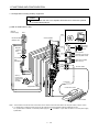
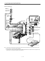
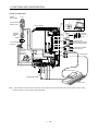
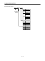
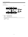
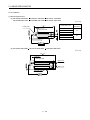
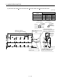
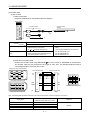
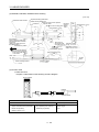
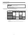
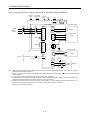
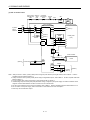
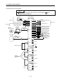
1.7 Configuration including auxiliary equipment
POINT
Equipment other than the servo amplifier and linear servo motor are optional
or recommended products.
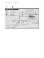
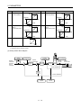
(1) MR-J3-100B-RJ004 or less
(Note 2)
Power supply
Personal
computer
MR Configurator
RST
CN5
No-fuse breaker
(NFB) or fuse
Servo amplifier
Junction
terminal
block
CN3
Magnetic
contactor
(MC)
Servo system
controller or Front axis
servo amplifier CN1B
CN1A
(Note 1)
Line noise
filter
(FR-BSF01)
CN1B
U
VW
Rear servo amplifier
CN1A or Cap
CN2
Encoder cable
CN2L
L1
L2
L3
(Note 1)
Power factor
improving DC
reactor
(FR-BEL)
P1
Thermistor
P2
P
C
Regenerative option
Linear servo motor
L11
L21
Linear encoder
Note 1. The AC reactor can also be used. In this case, the DC reactor cannot be used. When not using DC reactor, short P1 and P2.
2. A 1-phase 200V to 230VAC power supply may be used with the servo amplifier of MR-J3-70B-RJ004 or less.
For 1-phase 200V to 230VAC, connect the power supply to L1 L2 and leave L3 open. Refer to section 1.2 for the power supply
specification.
1 - 14
1. FUNCTIONS AND CONFIGURATION
(2) MR-J3-200B-RJ004
RST
(Note 2)
Power supply
No-fuse breaker
(NFB) or fuse
Magnetic
contactor
(MC)
MR Configurator
CN5
(Note 1)
Line noise filter
(FR-BSF01)
Servo amplifier
(Note 1)
Power factor
improving DC
reactor
(FR-BEL)
L1
L2
L3
P1
P2
L11
Personal
computer
Junction
terminal
block
CN3
(Note 3)
Servo system
controller or Front axis
servo amplifier CN1B
CN1A
Regenerative option P
C
CN1B
L21
Rear servo amplifier
CN1A or Cap
CN2
Encoder cable
CN2
Thermistor
Linear servo motor
UV
W
Linear encoder
Note 1. The AC reactor can also be used. In this case, the DC reactor cannot be used. When not using DC reactor, short P1 and P2.
2. Refer to section 1.2 for the power supply specification.
3. Connectors (CNP1, CNP2, and CNP3) and appearance of MR-J3-200B-RJ004 servo amplifier have been changed from April
2008 production. For existing servo amplifier, refer to appendix 5.
1 - 15
1. FUNCTIONS AND CONFIGURATION
(3) MR-J3-350B-RJ004
RST
(Note 2)
Power supply
No-fuse breaker
(NFB) or fuse
MR Configurator
Magnetic
contactor
(MC)
Personal
computer
CN5
(Note 1)
Servo amplifier
Line noise filter
(FR-BLF)
Junction
terminal
block
CN3
L1
L2
L3
CN1A
P1
Servo system
controller or Front axis
servo amplifier CN1B
P2
(Note 1)
Power factor
improving DC
reactor
(FR-BEL)
L11
CN1B
Regenerative P
option
C
Rear servo amplifier
CN1A or Cap
CN2
Encoder cable
CN2
L21
Thermistor
Linear servo motor
UV
W
Linear encoder
Note 1. The AC reactor can also be used. In this case, the DC reactor cannot be used. When not using DC reactor, short P1 and P2.
2. Refer to section 1.2 for the power supply specification.
1 - 16
1. FUNCTIONS AND CONFIGURATION
(4) MR-J3-500B-RJ004
(Note 2)
Power supply
RST
MR Configurator
No-fuse breaker
(NFB) or fuse
Personal
computer
CN5
Servo amplifier
Magnetic
contactor
(MC)
Junction
terminal
block
CN3
(Note 1)
CN1A
Line noise filter
(FR-BLF)
CN1B
Servo system
controller or Front axis
servo amplifier CN1B
Rear servo amplifier
CN1A or Cap
Thermistor
CN2
Encoder cable
CN2L
L11 L21
P1
P2
L3
(Note 1)
Power factor improving
DC reactor (FR-BEL)
L2
L1
Linear servo motor
P C
U V W
Regenerative option
Linear encoder
Note 1. The AC reactor can also be used. In this case, the DC reactor cannot be used. When not using DC reactor, short P1 and P2.
2. Refer to section 1.2 for the power supply specification.
1 - 17
1. FUNCTIONS AND CONFIGURATION
(5) MR-J3-700B-RJ004
RST
(Note 2)
Power supply
MR Configurator
No-fuse breaker
(NFB) or fuse
Personal
computer
CN5
Servo amplifier
Magnetic
contactor
(MC)
Junction
terminal
block
CN3
(Note 1)
CN1A
Line noise filter
(FR-BLF)
Servo system
controller or Front axis
servo amplifier CN1B
L11 L21
Rear servo amplifier
CN1A or Cap
CN1B
(Note 1)
Power factor
improving
DC reactor
(FR-BEL)
CN2
Encoder cable
CN2L
P2
L3
Thermistor
P1
L2
L1
P C U V W
Linear servo motor
Regenerative option
Linear encoder
Note 1. The AC reactor can also be used. In this case, the DC reactor cannot be used. When not using DC reactor, short P1 and P2.
2. Refer to section 1.2 for the power supply specification.
1 - 18
1. FUNCTIONS AND CONFIGURATION
(6) MR-J3-11KB-RJ004 MR-J3-15KB-RJ004
MR-J3-22KB4-RJ004
RST
(Note 2)
Power supply
MR Configurator
Personal
computer
CN5
No-fuse breaker
(NFB) or fuse
L21
Servo amplifier
L11
Magnetic
contactor
(MC)
Junction
terminal
block
CN3
(Note 1)
CN1A
Line noise filter
(FR-BLF)
Servo system
controller or Front axis
servo amplifier CN1B
Rear servo amplifier
CN1A or Cap
CN1B
CN2
Thermistor
Encoder cable
CN2L
L3
(Note 1)
Power factor
improving
DC reactor
(FR-BEL-(H))
L2
L1
Linear servo motor
P1
P
UV
P
W
C
Regenerative option
Linear encoder
Note 1. The AC reactor can also be used. In this case, the DC reactor cannot be used. When not using DC reactor, short P1 and P2.
2. Refer to section 1.2 for the power supply specification.
1 - 19
1. FUNCTIONS AND CONFIGURATION
MEMO
1 - 20
2. LINEAR SERVO MOTOR
2. LINEAR SERVO MOTOR
The secondary side of the linear servo motor contains a strong permanent magnet. The wrong handling may
cause serious accidents, which is extremely dangerous. Please read this chapter carefully beforehand and use
it correctly.
2.1 Handling
2.1.1 General instructions
The linear servo motor uses a strong magnet on the secondary side. Therefore,
not only the linear servo motor installation operators but also the machine
operators must use abundance of caution. For example, one who uses a medical
device like a pacemaker must keep away from the machine.
WARNING
The permanent magnet on the secondary side makes the magnetic bodies
generate suction. Use caution with accidents so as not to get your hand stuck.
The performance is not guaranteed if the specified servo amplifier and linear
servo motor are not combined. If used with unspecified combination, the servo
amplifier or linear servo motor may be damaged. Depending on the case, it can
be out of control and operate unexpectedly, resulting in extremely dangerous
condition.
The linear servo motor installation operators and machine operators must not
work wearing electronic devices (watch, calculator, personal computer, etc.) and
magnetic recording media (IC card, magnetic card, floppy disc, etc.) and must not
bring them around a magnetic. The magnetic influence may cause the operation
failure or malfunction.
The protection method of the linear servo motor is IP00. Take necessary
measures against dust, oil, etc. (Refer to section 2.1.2 Installation direction.)
When the linear servo motor is damaged, it must be replaced. Contact Mitsubishi
Electric System & Service Co., Ltd.
CAUTION
When the protective function is operated, turn off the power immediately and
eliminate its cause, and then turn it on again. If the linear servo motor is continued
operating without eliminating the cause, it may run unexpectedly and results in a
damage and injury.
Take safety measures, e.g. provide covers, to prevent accidental contact of
hands and parts (cables, etc.) with the servo amplifier heat sink, regenerative
resistor, linear servo motor, etc. since they may be hot while power is on or for
some time after power-off. Their temperatures may be high and you may get
burnt or a parts may damaged.
The primary side (coil) and secondary side (magnet) may be damaged by a fall or
shock.
2- 1
2. LINEAR SERVO MOTOR
2.1.2 Instructions on design
CAUTION
The dynamic brake can be applied to the servo amplifier, but the coasting distance
becomes longer when the moving body is heavy or when the speed is high. It may
result in crashing into the stroke edge, which is highly dangerous. Install the anticrash mechanism such as an air brake or an electric/mechanical stopper such as a
shock absorber to reduce the shock of movable parts. (No linear servo motor with
an electromagnetic brake is available.)
The magnetic suction power acting between the primary side (coil) and the
secondary (magnet) is always acting even when the motor power is not turned on.
Because of this, the machine must be designed to be rigid enough to resist the
magnetic suction power and maintain the accuracy.
The running load by friction increases in proportion to the increase of the magnetic
suction power, so the design must be made to decrease as much friction as
possible, for example, by mounting guides with high accuracy.
Do not use for vertical motion applications since magnetic poles cannot be
detected with a vertical application.
Install the linear servo motor the way in which the thrust acts on the gravity center
of the movable part. When the thrust does not act on the gravity center of the
movable part, the moment is generated.
Design the mounting dimensions to be satisfied for the primary side (coil) and
secondary side (magnet).
The cables such as power cables deriving from the primary side (coil) cannot stand
the long-term flexing action. Avoid the flexing action by fixing to the movable part,
etc. Also, use the cable that stands the long-term flexing action for the wiring to the
servo amplifier.
Magnetic chips such as iron fragments can be attached to the permanent magnet
on the secondary side, which may cause a malfunction. In the environment like
this, take measures against the attachment and entry of magnetic chips.
When the linear servo motor is operated over a long term under the condition
where water for cutting or lubrication oil is splashed or where oil mist or dew
condensation occurs due to supercooling or high humidity, insulation deterioration
or other failures may be caused. Prevent the linear servo motor from oil and dust
with a cover and take measures against dew condensation.
More careful measures against oil and dust must be taken for the linear encoder
than the linear servo motor. For details, please contact the linear encoder
manufacturer individually.
The moving direction of the linear servo motor and linear encoder must be
matched. Otherwise, the motor may run unexpectedly.
When two or more secondary side (magnet) is mounted, set the mounting screw
accumulative pitch tolerance within 0.2mm. Clearance may be left between the
secondary sides (magnets) depending on the mounting method and the numbers.
Do not hit the primary side (coil) on the stopper. The primary side may be
damaged. Design the machine so that the stopper is hit on the top table attached to
the primary side (coil).
2- 2
2. LINEAR SERVO MOTOR
POINT
To execute the high accuracy positioning, ensure as much rigidity of machine
as possible and make the machine resonance point higher.
Make the moving parts as light as possible and make the base parts heavier
and sturdier.
As the operation and accuracy of machine could have an adverse effect,
design it in order to make the thrust center of the linear servo motor closer to
a moving body's gravity center.
When the mounting rigidity of the linear encoder is not enough, machine
vibration, etc. affect the feedback signal, and the desired performance may
not be satisfied. As it is also the same case when the linear encoder is
susceptible to electric noise, set up and mount the linear encoder so that it is
affected by as little vibration and noise as possible.
Establish the structure to sustain the high-speed and the high acceleration
and deceleration.
2.1.3 Instructions on installation operation
Under the packaged condition (cardboard) delivered from our company, the
magnet on the secondary side does not have a serious effect on the outside.
Before mounting to the machine, however, magnetic bodies (including tools) must
be kept away from the secondary side (magnetic). The secondary side (magnetic)
can have as double suction power as mounted normally, which may cause a
serious injury. To avoid this, pay full attention to the ambience of workplace.
Magnetic body such as iron
WARNING
Secondary side (magnet)
Magnetic suction power: Max. 5 ton
The permanent magnet on the secondary side makes the magnetic bodies
generate suction, which may cause troubles such as having hands pinched, etc.
For the installation of the linear servo motor and the work around it, be sure to use
nonmagnetic tools. These are required for the improvement of workability and
safety ensuring. Use special caution with mounting the primary side (coil) after the
secondary side (magnet) has mounted. Use the screw which strength must be a
high tensile strength steel level of SCM435 for its material and the lower yield point
2
900 [N/mm ] or more. (Example) Explosion-proof beryllium copper alloy safety
tools: Manufactured by NGK Insulators, Ltd.
CAUTION
Do not install the servo motor, linear servo motor and regenerative resistor on or
near combustibles. Otherwise a fire may cause.
Securely attach the linear servo motor to the machine. If attach insecurely, it may
come off during operation.
Install the servo amplifier in a load-bearing place in accordance with the
Instruction Manual.
2- 3
2. LINEAR SERVO MOTOR
CAUTION
Do not subject the servo amplifier and linear servo motor to drop impact or shock
loads as they are precision equipment.
Do not install or operate a faulty servo amplifier and linear servo motor.
Use the equipment within the specified environmental condition range. (For the
environmental condition, refer to section 1.2.)
Tap holes on the linear servo motor are for machine installation. Do not use for
other purposes.
Do not touch the linear servo motor with wet hands.
For installation, use all screw halls and tap holes prepared on the linear servo
motor.
When two or more secondary side (magnet) is mounted, set the mounting screw
accumulative pitch tolerance within 0.2mm. Clearance may be left between the
secondary sides (magnets) depending on the mounting method and the numbers.
2.1.4 Instructions on storage
CAUTION
Do not climb or stand on servo equipment. Do not put heavy objects on
equipment.
Be sure to follow the storage conditions (ambient temperature and humidity, etc.).
Store the product in the environment where the rain water is prevented from
splashing on and dust, oil, and chemical materials from attaching on.
Do not strike servo amplifier or linear servo motor.
Do not modify the linear servo motor.
When the equipment has been stored for an extended period of time, consult
Mitsubishi.
2.2 Inspection items
WARNING
Before starting maintenance and/or inspection, turn off the power and wait for 15
minutes or more until the charge lamp turns off. Then, confirm that the voltage
between P( ) and N( ) is safe with a voltage tester and others. Otherwise, an
electric shock may occur. In addition, always confirm from the front of the servo
amplifier whether the charge lamp is off or not.
Any person who is involved in inspection should be fully competent to do the work.
Otherwise, you may get an electric shock. For repair and parts replacement,
contact your safes representative.
POINT
When executing a megger test (insulation resistance test), disconnect the
servo amplifier. Otherwise, a fault may occur.
Do not disassemble and/or repair the equipment on customer side.
The molded resin of the linear servo motor may lose the color. Though a fault
may not occur only for losing the color, make inspections.
It is not until the linear servo motor is mounted in equipment (built-in) that it has functions as motor. As the
protection method is IP00, it is recommended to make inspections and clean periodically.
2- 4
2. LINEAR SERVO MOTOR
2.2.1 Inspections on primary side (coil)
(1) Attachment of water and oil
Check that the primary side (coil) and secondary side (magnet) have not got wet with water and oil. When
the linear servo motor has got wet, the insulation on the primary side (coil) is deteriorated, which may cause
failure. Make sure to establish the mechanical structure in which water and oil are not attached to the linear
motor.
(2) Molded resin
Check for missing or cracks of the molded resin on the primary side (coil). As the insulation deterioration
and such may cause failure when missing or cracks are found in the molded resin on the primary side (coil),
replace the primary side (coil).
(3) Scratches of primary side (coil) facing secondary side (magnet)
Check the scratches of the primary side (coil) facing the secondary side (magnet). When the primary side
(coil) facing the secondary side (magnet) has scratches, replace the primary side (coil). When a foreign
matter is caught in the empty clearance between the primary side (coil) and the secondary side (magnet), a
scratch occurs on the primary side (coil). In such case, take away the corresponding matter and establish
the mechanical structure which does not catch such matters.
However, if the scratches of the primary side (coil) facing the secondary side (magnet) result in no more
than the protective coating peeled off, they can be repaired.
(4) Loose mounting screws
Check for loose mounting screws on the primary side (coil). When the mounting screws on the primary side
(coil) are loose, tighten the corresponding screws.
(5) Scratches and cracks of linear servo motor cables
Check for scratches and cracks of the linear servo motor cables. If the linear servo motor cables have any
scratches or cracks, replace the corresponding cables. Especially when the cables are moved, make
inspections periodically.
2- 5
2. LINEAR SERVO MOTOR
2.2.2 Inspections on secondary side (magnet)
(1) Attachment of water and oil
Check that the primary side (coil) and secondary side (magnet) have not got wet with water and oil. When
the linear servo motor has got wet, the insulation on the primary side (coil) is deteriorated, which may cause
failure. Make sure to establish the mechanical structure in which water and oil are not attached to the linear
motor.
(2) Exposure and lift of magnet
Check for the exposure and lift of the magnet on the secondary side (magnet). If the magnet on the
secondary side (magnet) is exposed or lifted, replace the secondary side (magnet) immediately.
(3) Molded resin
(a) Check for missing or cracks of the mold resin on the secondary side (magnet). (a) When missing or
cracks are found in the molded resin on the secondary side (magnet), replace the secondary side
(magnet).
(b) Check for the scratches of the molded resin on the secondary side (magnet). When the magnet is
exposed by the scratches of the molded resin on the secondary side (magnet), replace the secondary
side (magnet). When a foreign matter is caught in the empty clearance between the primary side (coil)
and the secondary side (magnet), a scratch occurs on the secondary side (magnet). In such case, take
away the corresponding matter and establish the mechanical structure which does not catch such
matters.
(4) Loose mounting screws
Check for loose mounting screws on the secondary side (magnet). When the mounting screws on the
secondary side (magnet) are loose, tighten the corresponding screws.
2.2.3 Inspections of linear encoder
The inspections of the linear encoder may be required. For the inspections of the linear encoder, contact the
linear encoder manufacturer.
2- 6
2. LINEAR SERVO MOTOR
2.3 Replacement of linear servo motor on absolute position detection system
2.3.1 Replacement of primary side (coil) or secondary side (magnet)
After replacing the primary side (coil) or the secondary side (magnet), perform the magnetic pole detecting
operation again.
2.3.2 Replacement of linear encoder
After replacing the linear encoder, perform the magnetic pole detecting operation again. When replacing the
linear encoder, make sure to set a home position by controller.
The following indicates the procedures to check the mounting position.
(1) Checking mounting position of linear encoder
1) Before replacing the linear encoder, check the encoder information using the MR Configurator with
the linear servo motor fixed at the specified position.
2) Replace the linear encoder so that the position gap should be
the replacement.
0.1 mm, comparing before and after
3) After replacing the linear encoder, check the encoder information using the MR Configurator again
with the linear servo motor fixed at the specified position.
4) Check that the value calculated from the difference of the encoder information (resolution unit) before
and after the replacement of the linear encoder is under 0.1mm.
(2) Reading encoder information with MR Configurator
1) Select the "MR-J3-B Linear" from the system setting of MR Configurator.
2) Check that the personal computer is connected with the servo amplifier and select "Diagnostics" and
then "Linear diagnostics".
The following window appears.
1)
3) Data 1 (1) of the encoder information is read.
2- 7
2. LINEAR SERVO MOTOR
2.4 Instructions for discarding the linear servo motor
Demagnetize the secondary side (magnet) of the linear servo motor by heating over 300
discard it in accordance with Law for Promotion of Effective Utilization of Resources.
(572 ), then
The linear servo motor uses a strong magnet on the secondary side. Therefore,
not only the operators but also the people around the work place must use
abundance of caution when the linear servo motor is disassembled or discarded.
For example, one who uses a medical device like a pacemaker must keep away
from the machine.
The permanent magnet on the secondary side makes the magnetic bodies
(primary side [coil] and secondary side [magnet]) generate suction.
Use special caution with the handling of the secondary side which is
demagnetized before/after disassembly.
WARNING
When the linear servo motor is disassembled or discarded, do not put magnetic
bodies (including the primary side [coil], the other secondary sides [magnet] and
tools) close to the secondary side (magnet). The secondary side (magnetic) can
have as double suction power as mounted normally, which may cause a serious
injury. In all cases, pay full attention to the ambience of workplace to avoid this.
Magnetic body such as iron
Secondary side (magnet)
Magnetic suction power: Max. 5 ton
A suction power is generated when magnetic bodies (including tools) are put near
the permanent magnet on the secondary side. Be sure to use nonmagnetic tools
for the disassembly and disposal of the linear servo motor or the work around it.
These are required for the improvement of workability and safety ensuring.
CAUTION
The personnel who work for the disassembly or disposal of the linear servo motor
or those who are around the workplace must not work wearing electronic devices
(watch, calculator, personal computer, etc.) and magnetic recording media (IC
card, magnetic card, floppy disc, etc.) and must not bring them around the
secondary side (magnet). Magnetic influence may cause the operation failure or
malfunction.
When the linear servo motor is disassembled or discarded, use cautions in order
to avoid accidents so as not to get your hand stuck.
Do not touch the secondary side after the demagnetization of the secondary side
(magnet) by heating over 300 (572 ) until it becomes cool enough. Otherwise,
you may get burnt.
2- 8
2. LINEAR SERVO MOTOR
2.5 LM-H2 series
2.5.1 Model code definition
(1) Primary side: coil
Symbol
Motor model
4SS0 LM-H2P1A-06M
LM-H2P2A-12M
LM-H2P2B-24M
LM-H2P2C-36M
LM-H2P2D-48M
1SS0
LM-H2P3A-24M
LM-H2P3B-48M
LM-H2P3C-72M
LM-H2P3D-96M
Series
Primary side
(coil)
Maximum speed: 2m/s
Rated thrust
Symbol Rated thurst [N]
06
60
12
120
24
240
36
360
48
480
72
720
96
960
Length (nominal dimensions)
Symbol Dimensions [mm]
A
128
B
224
C
320
D
416
Width (nominal dimensions)
Symbol Dimensions [mm]
1
50
2
70
3
110
2- 9
2. LINEAR SERVO MOTOR
(2) Secondary side: magnet
Symbol
Series
Secondary side
(magnetic)
4SS0
1SS0
Motor model
LM-H2S10-288
LM-H2S10-384
LM-H2S10-480
LM-H2S10-768
LM-H2S20-288
LM-H2S20-384
LM-H2S20-480
LM-H2S20-768
LM-H2S30-288
LM-H2S30-384
LM-H2S30-480
LM-H2S30-768
Length (nominal dimensions)
Symbol Dimensions [mm]
288
288
384
384
480
480
768
768
Width (nominal dimensions)
Symbol Dimensions [mm]
42
1
2
65
3
105
2 - 10
2. LINEAR SERVO MOTOR
2.5.2 LM-H2 series specification list
Linear servo motor
(Primary side) LM-H2
P1A-06M4SS0
Linear servo motor
(Secondary side) LM-H2
S10-2884SS0
S10-3844SS0
S10-4804SS0
S10-7684SS0
40B-RJ004
U500
Servo amplifier model
MR-J3Power supply capacity
Thrust
Rated (Note 2)
Maximum
Maximum speed (Note 1)
P2B24M1SS0
P2D48M1SS0
P3A24M1SS0
70BRJ004
U502
200BRJ004
U503
P3C72M1SS0
P3D96M1SS0
S30-288-1SS0
S30-384-1SS0
S30-480-1SS0
S30-768-1SS0
S20-288-1SS0
S20-384-1SS0
S20-480-1SS0
S20-768-1SS0
40BRJ004
U501
P3B48M1SS0
200BRJ004
U504
70BRJ004
U505
200BRJ004
U506
350BRJ004
U507
500BRJ004
U508
0.9
0.9
1.3
3.5
3.5
1.3
3.5
5.5
7.5
[N]
60
120
240
360
480
240
480
720
960
[N]
150
300
600
900
1200
600
1200
1800
2400
1000
1900
2700
3500
2000
3700
5300
7000
[N]
2
500
Recommended load mass ratio
Less than 30 times of mass of linear servo motor primary side
Structure
Open (Protection type: IP00)
Cooling system
Self-cooled
In
operation
Ambient
temperature
In storage
EnvironAmbient
mental
humidity
conditions
[ ]
0 to 40 (non-freezing)
[ ]
32 to 104 (non-freezing)
[ ]
15 to 70 (non-freezing)
[ ]
5 to 158 (non-freezing)
In operation
80%RH or less (non-condensing)
In storage
90%RH or less (non-condensing)
Indoors (no direct sunlight)
Free from corrosive gas, flammable gas, oil mist, dust and dirt.
Ambience
Vibration
[m/s2]
X, Y: 49 or less
Altitude
Primary side (coil)
Mass
P2C36M1SS0
[kVA]
[m/s]
Magnetic suction
P2A12M1SS0
Secondary side
(magnet)
Max, 1000m above sea level
[kg]
0.9
1.4
2.5
3.6
4.7
2.4
4.3
6.2
8.1
[lb]
1.98
3.09
5.51
7.94
10.4
5.29
9.48
13.7
17.9
0.6 (288mm
one magnet)
0.8 (384mm
one magnet)
[kg]
1.0 (480mm
one magnet)
1.6 (768mm
one magnet)
1.1 (288mm one magnet)
1.4 (384mm one magnet)
1.8 (480mm one magnet)
2.9 (768mm one magnet)
3.2 (288mm one magnet)
4.3 (384mm one magnet)
5.3 (480mm one magnet)
8.5 (768mm one magnet)
1.32 (288mm
one magnet)
1.76 (384mm
one magnet)
[lb]
2.21 (480mm
one magnet)
3.53 (768mm
one magnet)
2.43 (288mm one magnet)
3.09 (384mm one magnet)
3.97 (480mm one magnet)
6.39 (768mm one magnet)
7.06 (288mm one magnet)
9.48 (384mm one magnet)
11.7 (480mm one magnet)
18.7 (768mm one magnet)
2 - 11
2. LINEAR SERVO MOTOR
Note 1. Max. speed of the linear servo motor is smaller value of any max. speed of the linear servo motor and rated speed of the
encoder.
2. Value in the case where the aluminum board of the following dimensions (L[mm]
W[mm]
H[mm]) is mounted on the
primary side (coil). (Reference value)
LM-H2P3A-24M-1SS0: 192 495 30
LM-H2P1A-06M-4SS0: 192 225 30
LM-H2P2A-12M-1SS0: 192 315 30
LM-H2P3B-48M-1SS0: 336 495 40
LM-H2P2B-24M-1SS0: 336 315 30
LM-H2P3C-72M-1SS0: 480 495 40
LM-H2P2C-36M-1SS0: 480 315 40
LM-H2P3D-96M-1SS0: 624 495 40
LM-H2P2D-48M-1SS0: 624 315 40
2 - 12
2. LINEAR SERVO MOTOR
2.5.3 Thrust characteristics
When the input power supply specifications of the servo amplifier are 3-phase 200VAC or 1-phase 200VAC,
the thrust characteristic is indicated by the continuous line.
The continuous/max. thrust and max. speed of the linear servo motor are in the case of the rated power
voltage and frequency of the combined servo amplifier.
[LM-H2P1A-06M-4SS0]
[LM-H2P2A-12M-1SS0]
300
60
50
600
Short-duration
running region
200
120
100
Continuous
running region
0
1
0
2
0
Speed [m/s]
Short-duration
running region
Thrust [N]
Short-duration
running region
800
Short-duration
running region
400
240
200
Continuous
running region
0
2
2
[LM-H2P3A-24M-1SS0]
480
400
1
1
Speed [m/s]
600
Continuous
running region
0
0
0
Speed [m/s]
1
Continuous
running region
0
2
0
Speed [m/s]
1
2
Speed [m/s]
[LM-H2P3B-48M-1SS0]
[LM-H2P3C-72M-1SS0]
[LM-H2P3D-96M-1SS0]
1200
1800
2400
Thrust [N]
Short-duration
running region
800
480
400
Short-duration
running region
1200
720
600
960
900
Continuous
running region
0
0
1
Speed [m/s]
Short-duration
running region
Thrust [N]
Thrust [N]
0
2
1200
360
300
Thrust [N]
1
Continuous
running region
[LM-H2P2D-48M-1SS0]
900
0
240
200
Speed [m/s]
[LM-H2P2C-36M-1SS0]
600
Short-duration
running region
400
Continuous
running region
Thrust [N]
0
Thrust [N]
Short-duration
running region
100
Thrust [N]
Thrust [N]
150
[LM-H2P2B-24M-1SS0]
Continuous
running region
2
0
0
1
Speed [m/s]
2 - 13
Continuous
running region
2
0
0
1
Speed [m/s]
2
2. LINEAR SERVO MOTOR
2.5.4 Installation
(1) Mounting dimensions
[Unit: mm]
H
0.5 or less
0.1(Note 3)
Center on the primary side (coil) (Note 1)
0.1
0.1
A
A
0.1
Center on the secondary side (magnet) (Note 2)
Note 1. Centers on the primary side (coil) are as follows.
LM-H2P1 - : Center mounting screw position
LM-H2P2 - : Center of mounting screw pitch
LM-H2P3 - : Center mounting screw position
2. Centers on the secondary side (magnet) is the center of mounting screw pitch.
3. H length indicates (height of primary side (coil)) + (height of secondary side (magnet)) + (length of empty clearance: 0.5mm).
LM-H2P1 - : H= 43.0mm
LM-H2P2 - : H= 43.0mm
LM-H2P3 - : H= 48.0mm
2 - 14
2. LINEAR SERVO MOTOR
(2) Mounting the secondary side (magnet)
WARNING
The linear servo motor uses a strong magnet on the secondary side. Therefore,
not only the servo motor installation operators but also the machine operators
must use abundance of caution. For example, one who uses a medical device like
a pacemaker must keep away from the machine.
When mounting the secondary side (magnet), use nonmagnetic tools.
CAUTION
When the additional secondary side (magnet) is mounted after one has been
already set, slide the additional secondary side (magnet) to mount in the specified
position after setting in the position away from the one already mounted as shown
in this section.
When two or more secondary side (magnet) is mounted, set the mounting screw
accumulative pitch tolerance within 0.2mm. Clearance may be left between the
secondary sides (magnets) depending on the mounting method and the numbers.
When using multiple secondary sides (magnets), arrange the name plates attached to the products on the
same side for keeping the layout of magnetic poles.
Name plate
In order to decrease the clearance between the secondary sides (magnets), mount them with the following
procedure.
Procedure 1. Securely fix with bolts the secondary side (magnet) to be a mounting standard.
Secondary side (magnet) to be a mounting standard
Procedure 2. Set the secondary side (magnet) on the mounting face and fix it with bolts as temporary joint.
Secondary side (magnet) to be a mounting standard
Procedure 3. Press the secondary side (magnet) fixed as temporary joint toward that to be a mounting
standard.
Secondary side (magnet) to be
a mounting standard
2 - 15
2. LINEAR SERVO MOTOR
Procedure 4. Securely fix with bolts the secondary side (magnet) fixed as temporary joint.
Secondary side (magnet) to be a mounting standard
(3) Mounting the primary side (coil)
To avoid the danger caused by suction, which is generated between the primary
side (coil) and the secondary side (magnet) by the permanent magnet, it is
recommended to mount the primary side (coil) in the position free from the
secondary side (magnet) as shown in this section.
CAUTION
When mounting the primary side (coil) over the secondary side (magnet)
unavoidably, use the material handling equipment such as crane which is fully
competent to sustain the load of suction, etc.
When sliding the primary side (coil) to move over the secondary side (magnet)
after setting, pay full attention to the suction generated.
Procedure 1. Mount a part of the secondary side (magnet).
Procedure 2. Mount the primary side (coil) in the position free from the secondary side (magnet).
Procedure 3. Move the primary side (coil) over the secondary side (magnet) mounted.
Confirm that the primary side (coil) does not contact the secondary side (magnet).
Procedure 4. Mount the rest of the secondary side (magnet).
2 - 16
2. LINEAR SERVO MOTOR
2.5.5 Outline drawings
(1) Primary side (coil)
(a) LM-H2P1A-06M-4SS0
[Unit: mm]
Lead for motor (U, V, W): black,earth (E): green/yellow
4 wires-AWG20 (Standard finish OD 2.12 mm)
Active length 400 mm
43.0
128
400
40
0
(Lead active length)
32
32
32
32
Approx.0.7
Round crimping terminal
210
Approx.10.5
31.8
1.25-4
Approx.3.5
Approx.
40
Wire mark
Secondary side
3-M5 screw depth 6.5
Lead for thermistor (G1, G2): black
2 wires-AWG20 (Standard finish OD
Active length 400 mm
Round crimping terminal
1.25-2
2.12 mm)
(b) LM-H2P2A-12M-1SS0 LM-H2P2B-24M-1SS0 LM-H2P2C-36M-1SS0 LM-H2P2D-48M-1SS0
[Unit: mm]
Variable dimensions
Model
Lead for motor
L
M
A
B
LM-H2P2A-12M-1SS0
128
64
(32)
2
2
LM-H2P2B-24M-1SS0
224
2
64( 128)
(64)
3
2
LM-H2P2C-36M-1SS0
320
4
64( 256)
(32)
5
2
LM-H2P2D-48M-1SS0
416
5
64( 320)
(64)
6
2
Lead for motor (U, V, W): black, earth (E): green/yellow
Active length 400 mm
L
A
Size
32
2.12
AWG16
2.7
Round crimping
terminal 1.25-4
Approx. 0.7
(Lead active
Approx. 10.5
Approx. 3.5
31.8
210 length)
Approx.
40
64
AWG20
4
40
M
Standard finish
OD
E
U
V
W
Wire mark
B-M5 screw depth 6.5 (For primary side)
Lead for thermistor (G1, G2): black
2 wires-AWG20 (Standard finish OD
Active length 400 mm
2 - 17
2.12 mm)
G1
G2
Secondary
side
Round crimping terminal
1.25-4
2. LINEAR SERVO MOTOR
(c) LM-H2P3A-24M-1SS0 LM-H2P3B-48M-1SS0 LM-H2P3C-72M-1SS0 LM-H2P3D-96M-1SS0
[Unit: mm]
Variable dimensions
Model
L
M
A
64
Lead for motor
B
LM-H2P3A-24M-1SS0
128
32
2
3
LM-H2P3B-48M-1SS0
224
2
64( 128)
64
3
3
LM-H2P3C-72M-1SS0
320
4
64( 256)
32
5
3
LM-H2P3D-96M-1SS0
416
5
64( 320)
64
6
3
Lead for motor (U, V, W): black, earth (E): green/yellow
Active length 400 mm
L
400
M
32
210
Approx.
40
AWG20
2.12
AWG14
3.12
Round crimping terminal
1.25-4
48
Approx. 0.7
(Lead active length)
A
Standard finish
OD
Size
Approx. 15.5
31.8
Approx. 8.5
E
U
V
W
Wire mark
B-M5 screw depth 6.5
(For primary side mounting)
G1
Lead for thermistor (G1, G2): black
2 wires-AWG20 (Standard finish OD
Active length 400 mm
G2
Secondary side
2.12 mm)
Round crimping terminal
1.25-4
(2) Secondary side (magnet)
(a) LM-H2S10- -1SS0
[Unit: mm]
Variable dimensions
Model
L
M
288
5
48( 240)
6
2
LM-H2S10-384
384
7
48( 336)
8
2
LM-H2S10-480
480
9
48( 432)
10
2
LM-H2S10-768
768
15
48( 720)
16
2
Overall length L
Approx.
24
B
LM-H2S10-288
M
24
Mark "N"
7
10.5 or less
3.5
48
Name plate
B-
4.8 For mounting the secondary side
2 - 18
N
2-C1
2. LINEAR SERVO MOTOR
(b) LM-H2S20-
-1SS0
[Unit: mm]
Variable dimensions
Model
L
M
B
LM-H2S20-288
288
5
48( 240)
6
2
LM-H2S20-384
384
7
48( 336)
8
2
LM-H2S20-480
480
9
48( 432)
10
2
LM-H2S20-768
768
15
48( 720)
16
2
Overall length L
Approx.
24
M
24
Mark "N"
10.5 or less
3.5
7
48
N
Name plate
B-
(c) LM-H2S30-
5.8 For mounting the secondary side
2-C1
-1SS0
[Unit: mm]
Variable dimensions
Model
L
M
LM-H2S30-288
288
5
48( 240)
6
2
LM-H2S30-384
384
7
48( 336)
8
2
LM-H2S30-480
480
9
48( 432)
10
2
LM-H2S30-768
768
15
48( 720)
16
2
Overall length L
Approx.
24
M
24
Mark "N"
7
15.5 or less
8.5
48
Name plate
B-
5.8 For mounting the secondary side
2 - 19
B
N
2-C1
2. LINEAR SERVO MOTOR
2.5.6 Connection of servo amplifier and linear servo motor
(1) Connection instructions
WARNING
Insulate the connections of the power supply terminals to prevent an electric
shock.
CAUTION
Connect the wires to the correct phase terminals (U, V, W) of the servo amplifier
and linear servo motor. Otherwise, the linear servo motor does not operate
properly.
Do not connect AC power supply directly to the linear servo motor. Otherwise, a
fault may occur.
POINT
Refer to section 11.1 for the selection of the encoder cable.
For grounding, connect the earth cable of the linear servo motor to the protective earth (PE) terminal of the
servo amplifier and connect the ground cable of the servo amplifier to the earth via the protective earth of the
control box. Do not connect them directly to the protective earth of the control panel.
Control box
Servo
amplifier
Linear servo motor
PE terminal
(2) Power supply cable wiring diagrams
Use the wires and connectors shown in the following figure. For the wires used for wiring, refer to section
4.2.1.
30m or less
Servo amplifier
Connector set (option)
MR-J3CN2
Receptacle: 36210-0100PE
Shell kit: 36310-3200-008
(3M or similar product)
(Note 1)
Lead supplied with
linear servo motor 0.4 m Linear servo motor
CN2
5 THM1
6 THM2
CNP3
U
V
W
G1 (Black)
G2 (Black)
U (Black)
V (Black)
W (Black)
E (Green/yellow)
Round crimping terminal
1.25-4
Note 1. The signal name (U, V, W, E, G1, G2) is attached on leads.
2. No polarity for the thermistors (G1 and G2)
2 - 20
(Note 2)
Primary
side
(coil)
2. LINEAR SERVO MOTOR
2.6 LM-U2 series
2.6.1 Model code definition
(1) Medium thrust series
(a) Primary side: coil
Series
Symbol
0SS0
Primary side
(coil)
1SS0
Motor model
LM-U2PAB-05M
LM-U2PAD-10M
LM-U2PAF-15M
LM-U2PBB-07M
LM-U2PBD-15M
LM-U2PBF-22M
Maximum speed: 2m/s
Rated thrust
Symbol Rated thurst [N]
50
05
75
07
100
10
150
15
225
22
Length (nominal dimensions)
Symbol Dimensions [mm]
B
130
D
250
F
370
Width (nominal dimensions)
Symbol Dimensions [mm]
A
66.5
B
86.5
(b) Secondary side: magnet
Symbol
Series
Secondary side
(magnetic)
0SS0
1SS0
Motor model
LM-U2SA0-240
LM-U2SA0-300
LM-U2SA0-420
LM-U2SB0-240
LM-U2SB0-300
LM-U2SB0-420
Length (nominal dimensions)
Symbol Dimensions [mm]
240
240
300
300
420
420
Width (nominal dimensions)
Symbol Dimensions [mm]
A
62
B
82
2 - 21
2. LINEAR SERVO MOTOR
(2) Large thrust series
(a) Primary side: coil
Maximum speed: 2m/s
Series
Primary side
(coil)
Rated thrust
Symbol Rated thurst [N]
40
400
60
600
80
800
Length (nominal dimensions)
Symbol Dimensions [mm]
B
286
C
406
D
526
(b) Secondary side: magnet
Series
Secondary side
(magnetic)
Length (nominal dimensions)
Symbol Dimensions [mm]
300
300
480
480
2 - 22
2. LINEAR SERVO MOTOR
2.6.2 LM-U2 series specification list
Linear servo motor
(Primary side) LM-U2
PAB-05M0SS0
PAF-15M0SS0
20BRJ004U512
Servo amplifier MR-J3Power supply capacity
Rated (Note 2)
Maximum
Maximum speed (Note 1)
40BRJ004U513
PBD-15M1SS0
PBF-22M1SS0
SB0-240-1SS0
SB0-300-1SS0
SB0-420-1SS0
40BRJ004U514
20BRJ004U515
60BRJ004U516
70BRJ004U517
[kVA]
0.5
0.9
0.9
0.5
1.0
1.3
[N]
50
100
150
75
150
225
[N]
150
300
450
225
450
675
[m/s]
Magnetic suction
2.0
[N]
0
Recommended load mass ratio
Less than 30 times of mass of linear servo motor primary side
Structure
Open (Protection type: IP00)
Cooling system
Self-cooled
In
operation
Ambient
temperature
In storage
EnvironAmbient
mental
humidity
conditions
[ ]
0 to 40 (non-freezing)
[ ]
32 to 104 (non-freezing)
[ ]
15 to 70 (non-freezing)
[ ]
5 to 158 (non-freezing)
In operation
80%RH or less (non-condensing)
In storage
90%RH or less (non-condensing)
Indoors (no direct sunlight)
Free from corrosive gas, flammable gas, oil mist, dust and dirt.
Ambience
Vibration
[m/s2]
X, Y: 49 or less
Altitude
Primary side (coil)
Mass
PBB-07M1SS0
SA0-240-0SS0
SA0-300-0SS0
SA0-420-0SS0
Linear servo motor
(Secondary side) LM-U2
Thrust
PAD-10M0SS0
Max, 1000m above sea level
[kg]
0.3
[Ib]
0.66
0.6
0.8
0.4
1.32
1.76
0.88
0.8
1.1
1.76
2.43
[kg]
2.0(240mm One magnet)
2.5(300mm One magnet)
3.5(420mm One magnet)
2.6(240mm One magnet)
3.2(300mm One magnet)
4.5(420mm One magnet)
[Ib]
4.41(240mm One magnet)
5.51(300mm One magnet)
7.72(420mm One magnet)
5.74(240mm One magnet)
7.06(300mm One magnet)
9.92(420mm One magnet)
Secondary side
(magnet)
2 - 23
2. LINEAR SERVO MOTOR
Linear servo motor
(Primary side) LM-U2
P2B-40M-2SS0
Linear servo motor
(Secondary side) LM-U2
200B-RJ004U509
Power supply capacity
Rated (Note 2)
Maximum
Maximum speed (Note 1)
350B-RJ004U510
500B-RJ004U511
[kVA]
3.5
5.5
7.5
[N]
400
600
800
[N]
1600
2400
3200
[m/s]
Magnetic suction
2
[N]
Recommended load mass ratio
0
Less than 30 times of mass of linear servo motor primary side
Structure
Open (Protection type: IP00)
Cooling system
Ambient
temperature
EnvironAmbient
mental
humidity
conditions
Self-cooled
In
operation
In storage
[ ]
0 to 40 (non-freezing)
[ ]
32 to 104 (non-freezing)
[ ]
15 to 70 (non-freezing)
[ ]
5 to 158 (non-freezing)
In operation
80%RH or less (non-condensing)
In storage
90%RH or less (non-condensing)
Indoors (no direct sunlight)
Free from corrosive gas, flammable gas, oil mist, dust and dirt.
Ambience
Vibration
[m/s2]
X, Y: 49 or less
Altitude
Primary side (coil)
Mass
P2D-80M-2SS0
S20-300-2SS0
S20-480-2SS0
Servo amplifier MR-J3-
Thrust
P2C-60M-2SS0
Secondary side
(magnet)
Max, 1000m above sea level
[kg]
2.9
4.2
5.5
[lb]
6.39
9.26
12.1
[kg]
9.6 (300mm One magnet)
15.3 (480mm One magnet)
[lb]
21.2 (300mm One magnet)
3.38 (480mm One magnet)
Note 1. Max. speed of the linear servo motor is smaller value of any max. speed of the linear servo motor and rated speed of the
encoder.
2. Value in the case where the aluminum board of the following dimensions (L[mm]
W[mm]
H[mm]) is mounted on the
primary side (coil). (Reference value)
LM-U2PAB-05M-0SS0: 300 400 15
LM-U2PAD-10M-0SS0: 400 500 15
LM-U2PAF-15M-0SS0: 500 600 15
LM-U2PBB-07M-1SS0: 300 400 15
LM-U2PBD-15M-1SS0: 400 500 15
LM-U2PBF-22M-1SS0: 500 600 15
LM-U2P2B-40M-2SS0: 900 800 12
LM-U2P2C-60M-2SS0: 900 800 12
LM-U2P2D-80M-2SS0: 990 800 12
2 - 24
2. LINEAR SERVO MOTOR
2.6.3 Thrust characteristics
When the input power supply specifications of the servo amplifier are 3-phase 200VAC or 1-phase 230VAC,
the thrust characteristic is indicated by the continuous line.
The continuous/max. thrust and max. speed of the linear servo motor are in the case of the rated power
voltage and frequency of the combined servo amplifier.
[LM-U2PAD-10M-0SS0]
[LM-U2PAF-15M-0SS0]
180
360
540
150
300
450
Short-duration
running region
60
50
240
Short-duration
running region
120
100
0
1
360
Short-duration
running region
180
150
Continuous
running region
0
Thrust [N]
120
Thrust [N]
Thrust [N]
[LM-U2PAB-05M-0SS0]
Continuous
running region
0
2
0
Speed [m/s]
1
Continuous
running region
0
2
0
Speed [m/s]
[LM-U2PBB-07M-1SS0]
[LM-U2PBD-15M-1SS0]
300
1
2
Speed [m/s]
[LM-U2PBF-22M-1SS0]
540
720
675
450
Short-duration
running region
100
Short-duration
running region
180
150
75
0
360
Continuous
running region
0
1
480
Short-duration
running region
240
225
Continuous
running region
0
2
0
Speed [m/s]
1
Continuous
running region
0
2
0
Speed [m/s]
1
2
Speed [m/s]
[LM-U2P2B-40M-2SS0]
[LM-U2P2C-60M-2SS0]
[LM-U2P2D-80M-2SS0]
1600
2400
3200
400
Short-duration
running region
1500
600
0
1
Speed [m/s]
Short-duration
running region
2000
800
Continuous
running region
0
Thrust [N]
Short-duration
running region
800
Thrust [N]
Thrust [N]
Thrust [N]
200
Thrust [N]
Thrust [N]
225
Continuous
running region
2
0
0
1
Speed [m/s]
2 - 25
Continuous
running region
2
0
0
1
Speed [m/s]
2
2. LINEAR SERVO MOTOR
2.6.4 Installation
(1) Mounting dimensions
(a) LM-U2PAB-05M-0SS0 LM-U2PAD-10M-0SS0 LM-U2PAF-15M-0SS0
LM-U2PBB-07M-1SS0 LM-U2PBD-15M-1SS0 LM-U2PBF-22M-1SS0
[Unit: mm]
Primary side
L 0.1
Approx. 1
Name plate side
Linear servo motor
Variable
dimensions L
LM-U2PAB-05M-0SS0
LM-U2PAD-10M-0SS0
78
LM-U2PAF-15M-0SS0
LM-U2PBB-07M-1SS0
LM-U2PBD-15M-1SS0
98
LM-U2PBF-22M-1SS0
Secondary side
0.1
0.1
(b) LM-U2P2B-40M-2SS0 LM-U2P2C-60M-2SS0 LM-U2P2D-80M-2SS0
[Unit: mm]
138
0.3
Approx. 1
Name plate side
Approx. 0.9
Approx. 0.9
Secondary side
0.1
0.1
2 - 26
2. LINEAR SERVO MOTOR
(2) Mounting the secondary side (magnet)
WARNING
The linear servo motor uses a strong magnet on the secondary side. Therefore,
not only the servo motor installation operators but also the machine operators
must use abundance of caution. For example, one who uses a medical device like
a pacemaker must keep away from the machine.
When mounting the secondary side (magnet), use nonmagnetic tools.
CAUTION
When the additional secondary side (magnet) is mounted after one has been
already set, slide the additional secondary side (magnet) to mount in the specified
position after setting in the position away from the one already mounted as shown
in this section.
When two or more secondary side (magnet) is mounted, set the mounting screw
accumulative pitch tolerance within 0.2mm. Clearance may be left between the
secondary sides (magnets) depending on the mounting method and the numbers.
When using multiple secondary sides (magnets), arrange the name plates attached to the products on the
same side for keeping the layout of magnetic poles.
Caution name plate
In order to decrease the clearance between the secondary sides (magnets), mount them with the following
procedure.
Procedure 1. Securely fix with bolts the secondary side (magnet) to be a mounting standard.
Secondary side
to be a mounting standard
Procedure 2. Set the secondary side (magnet) on the mounting face and fix it with bolts as temporary joint.
Secondary side
to be a mounting standard
Procedure 3. Press the secondary side (magnet) fixed as temporary joint toward that to be a mounting
standard.
Secondary side
to be a mounting standard
2 - 27
2. LINEAR SERVO MOTOR
Procedure 4. Securely fix with bolts the secondary side (magnet) fixed as temporary joint.
Secondary side
to be a mounting standard
(3) Mounting the primary side (coil)
Procedure 1. Mount a part of the secondary side (magnet).
Procedure 2. Mount the primary side (coil) in the position free from the secondary side (magnet).
Procedure 3. Move the primary side (coil) over the secondary side (magnet) mounted.
Confirm that the primary side (coil) does not contact the secondary side (magnet).
Procedure 4. Mount the rest of the secondary side (magnet).
2 - 28
2. LINEAR SERVO MOTOR
2.6.5 Outline drawings
(1) Primary side (coil)
(a) LM-U2PAB-05M-0SS0
LM-U2PAD-10M-0SS0 LM-U2PAF-15M-0SS0
[Unit: mm]
Variable dimensions
Model
L
M
Lead
B
U
LM-U2PAB-05M-0SS0
130
2
60 (=120) 2
3
LM-U2PAD-10M-0SS0
250
4
60 (=240) 2
5
LM-U2PAF-15M-0SS0
370
6
60 (=360) 2
7
V
W
E
0.14mm2 (AWG26)
(Standard finish 1.6mm)
G1
G2
0.14mm2 (AWG26)
(Standard finish 1.6mm)
L
Approx. 5
M
5
B-M4 screw, depth 7
60
(For primary side mounting)
Wire mark
Motor lead wire (U, V, W): Black
Grounding lead wire (E): Green/Yellow Effective length 400mm
Round crimp terminal (0.5-4)
24.5
Thermistor lead wire (G1, G2): Black Effective length 400mm
Round crimp terminal (0.5-4)
25
Secondary
side
210
400
(Effective lead length)
Approx. 0.8
6.4
Approx. 0.8
Approx. 25.4
2 - 29
2. LINEAR SERVO MOTOR
(b) LM-U2PBB-07M-1SS0
LM-U2PBD-15M-1SS0 LM-U2PBF-22M-1SS0
[Unit: mm]
Variable dimensions
Model
L
M
Lead
B
U
LM-U2PBB-07M-1SS0
130
2
60 (=120) 2
3
LM-U2PBD-15M-1SS0
250
4
60 (=240) 2
5
LM-U2PBF-22M-1SS0
370
6
60 (=360) 2
7
V
W
E
0.14mm2 (AWG26)
(Standard finish 1.6mm)
G1
G2
0.14mm2 (AWG26)
(Standard finish 1.6mm)
L
Approx. 5
M
5
B-M4 screw, depth 7
60
(For primary side mounting)
Wire mark
Motor lead wire (U, V, W): Black
Grounding lead wire (E): Green/Yellow Effective length 400mm
Round crimp terminal (0.5-4)
24.5
Thermistor lead wire (G1, G2): Black Effective length 400mm
Round crimp terminal (0.5-4)
25
Secondary
side
210
400
(Effective lead length)
Approx. 0.8
6.4
Approx. 0.8
Approx. 25.4
2 - 30
2. LINEAR SERVO MOTOR
(c) LM-U2P2B-40M-2SS0 LM-U2P2C-60M-2SS0 LM-U2P2D-80M-2SS0
[Unit: mm]
Variable dimensions
Model
L
M
Lead
C
U
V
W
E
G1
G2
2
LM-U2P2B-40M-2SS0
Approx. 23
286
4
60 (=240) 2
LM-U2P2C-60M-2SS0
406
6
60 (=360) 2
LM-U2P2D-80M-2SS0
526
8
60 (=480) 2
L
M
5
1.25mm (AWG16)
(Standard finish 2.7mm)
2
7
2mm (AWG14)
9 (Standard finish 3.12mm)
0.2mm2 (AWG24)
(Standard finish 2mm)
23
60
Wire
mark
B-M6 screw, depth 8
(For primary side mounting)
Motor lead wire (U, V, W): Black
Grounding lead wire (E): Green/Yellow
Effective length 400mm
Round crimp terminal
(40M: 1.25-4, 60M 80M: 2-4)
Secondary
side
49
50
21
400
Thermistor lead wire (G1, G2): Black
Effective length 400mm
Round crimp terminal (1.25-4)
2 - 31
Approx. 0.9
12
Approx. 0.9
Approx. 50.8
2. LINEAR SERVO MOTOR
(2) Secondary side (magnet)
(a) LM-U2SA0-240-0SS0
LM-U2SA0-300-0SS0 LM-U2SA0-420-0SS0
[Unit: mm]
Variable dimensions
Model
L
M
240
3
60 (=180)
4
LM-U2SA0-300-0SS0
300
4
60 (=240)
5
LM-U2SA0-420-0SS0
420
6
60 (=360)
7
L
Mark "N"
Mark "S"
N
S
S
N
Mark "S"
8
15
25.4
M
30
B-6 drill through, 10 counter boring, depth 6.2
(For secondary side mounting)
2 - 32
8.7
Primary side
60
30
8.7
Mark "N"
45
B
LM-U2SA0-240-0SS0
2-M6 screw, depth 6
(For grounding)
2. LINEAR SERVO MOTOR
(b) LM-U2SB0-240-1SS0 LM-U2SB0-300-1SS0 LM-U2SB0-420-1SS0
[Unit: mm]
Variable dimensions
Model
L
M
240
3
60 (=180)
4
LM-U2SB0-300-1SS0
300
4
60 (=240)
5
LM-U2SB0-420-1SS0
420
6
60 (=360)
7
L
Mark "N"
Mark "S"
N
S
S
N
8.7
Mark "S"
25.4
M
30
B-6 drill through, 10 counter boring, depth 6.2
(For secondary side mounting)
2 - 33
8.7
Primary side
15
60
30
8
Mark "N"
45
B
LM-U2SB0-240-1SS0
2-M5 screw, depth 8
(For grounding)
2. LINEAR SERVO MOTOR
(c) LM-U2S20-300-2SS0 LM-U2S20-480-2SS0
[Unit: mm]
Model
Variable dimensions
L
M
B
LM-U2S20-300-2SS0
300
3
60 (=180)
4
LM-U2S20-480-2SS0
480
6
60 (=360)
7
L
Mark "N"
Mark "S"
N
S
S
N
Mark "S"
15
60
18.5
Mark "N"
15
2-M6 screw, depth 6
(For grounding)
13.8
18.5
M
60
B-6.6 drill through, 11 counter boring, depth 25
(For secondary side mounting)
2 - 34
50.8
2. LINEAR SERVO MOTOR
2.6.6 Connection of servo amplifier and linear servo motor
(1) Connection instructions
WARNING
Insulate the connections of the power supply terminals to prevent an electric
shock.
CAUTION
Connect the wires to the correct phase terminals (U, V, W) of the servo amplifier
and linear servo motor. Otherwise, the linear servo motor does not operate
properly.
Do not connect AC power supply directly to the linear servo motor. Otherwise, a
fault may occur.
POINT
Refer to section 11.1 for the selection of the encoder cable.
For grounding, connect the earth cable of the linear servo motor to the protective earth (PE) terminal of the
servo amplifier and connect the ground cable of the servo amplifier to the earth via the protective earth of the
control box. Do not connect them directly to the protective earth of the control panel.
Control box
Servo
amplifier
Linear servo motor
PE terminal
(2) Power supply cable wiring diagrams
Use the wires and connectors shown in the following figure. For the wires used for wiring, refer to section
4.2.1.
30m or less
Servo amplifier
Connector set (option)
MR-J3CN2
Receptacle: 36210-0100PE
Shell kit: 36310-3200-008
(3M or similar product)
(Note 1)
Lead supplied with
linear servo motor 0.4 m Linear servo motor
CN2
5 THM1
6 THM2
CNP3
U
V
W
G1 (Black)
G2 (Black)
U (Black)
V (Black)
W (Black)
E (Green/yellow)
Round crimping terminal
1.25-4
Note 1. The signal name (U, V, W, E, G1, G2) is attached on leads.
2. No polarity for the thermistors (G1 and G2)
2 - 35
(Note 2)
Primary
side
(coil)
2. LINEAR SERVO MOTOR
2.7 LM-F series
2.7.1 Model code definition
(1) Primary side: coil
Series
Primary side
(coil)
Maximum speed: 2m/s
Rated thrust
Symbol
06
12
18
24
36
48
60
Rated thurst [N]
Self-cooled Liquid-cooled
600
300
1200
600
1800
900
2400
1200
3600
1800
4800
2400
6000
3000
Length (nominal dimensions)
Symbol Dimensions [mm]
B
290
D
530
F
770
H
1010
Width (nominal dimensions)
Symbol Dimensions [mm]
2
120
4
200
5
240
(2) Secondary side: magnet
Length (nominal dimensions)
Series
Secondary side
(magnetic)
Symbol Dimensions [mm]
480
480
576
576
Width (nominal dimensions)
Symbol Dimensions [mm]
2
120
4
200
5
240
2 - 36
2. LINEAR SERVO MOTOR
2.7.2 LM-F series specification list
Linear servo motor
(Primary side) LM-F
P2B-06M- P2D-12M- P2F-18M- P4B-12M- P4D-24M- P4F-36M- P4H-48M1SS0
1SS0
1SS0
1SS0
1SS0
1SS0
1SS0
Linear servo motor
(Secondary side) LM-F
S20-480-1SS0
S20-576-1SS0
500BRJ004
U520
700BRJ004
U522
500BRJ004
U524
700BRJ004
U526
11KBRJ004
U528
15KBRJ004
U530
22KB4RJ004
U532
200BRJ004
U519
3.5
500BRJ004
U521
5.5
700BRJ004
U523
10
500BRJ004
U525
7.5
700BRJ004
U527
18
11KBRJ004
U529
18
15KBRJ004
U531
18
22KB4RJ004
U533
Selfcooled
300
600
900
600
1200
1800
2400
3000
Liquidcooled
600
1200
1800
1200
2400
3600
4800
6000
[N]
1800
3600
5400
3600
7200
10800
14400
18000
18000
27000
36000
45000
Servo amplifier MR-J3Liquidcooled
Thrust
[kVA]
Rated (Note 2)
[N]
Maximum
Maximum speed (Note 1)
[m/s]
Magnetic suction
[N]
22
2.0
4500
Recommended load mass ratio
9000
13500
9000
Less than 15 times of mass of linear servo motor primary side
Structure
Open (Protection type: IP00)
Cooling system
Ambient
temperature
EnvironAmbient
mental
humidity
conditions
Self-cooled, Liquid-cooled
In
operation
[ ]
0 to 40 (non-freezing)
[ ]
32 to 104 (non-freezing)
[ ]
In storage
15 to 70 (non-freezing)
[ ]
5 to 158 (non-freezing)
In operation
80%RH or less (non-condensing)
In storage
90%RH or less (non-condensing)
Indoors (no direct sunlight)
Free from corrosive gas, flammable gas, oil mist, dust and dirt.
Ambience
Vibration
[m/s2]
X, Y: 49 or less
Altitude
Primary side (coil)
Max, 1000m above sea level
[kg]
9
18
27
14
28
42
56
67
[]Ib]
19.8
39.7
59.5
30.9
61.7
92.6
123
148
[kg]
Mass
S50-4801SS0
S50-5761SS0
S40-480-1SS0
S40-576-1SS0
200BRJ004
U518
Selfcooled
Power supply capacity
P5H-60M1SS0
(Note 3)
7.1(480mm One magnet)
9.0(576mm One magnet)
13.5(480mm One magnet)
16.0(576mm One magnet)
20.0
(480mm
One
magnet)
26.0
(576mm
One
magnet)
29.8(480mm One magnet)
35.3(576mm One magnet)
44.1
(480mm
One
magnet)
79.4
(576mm
One
magnet)
Secondary side
(magnet)
[Ib]
15.7(240mm One magnet)
19.8(300mm One magnet)
2 - 37
2. LINEAR SERVO MOTOR
Note 1. Max. speed of the linear servo motor is smaller value of any max. speed of the linear servo motor and rated speed of the
encoder.
2. Value in the case where the aluminum board of the following dimensions (L[mm]
W[mm]
H[mm]) is mounted on the
primary side (coil). (Reference value)
LM-FP2B-06M-1SS0: 280 250 50
LM-FP2D-12M-1SS0: 510 250 50
LM-FP2F-18M-1SS0: 740 250 50
LM-FP4B-12M-1SS0: 280 425 50
LM-FP4D-24M-1SS0: 500 425 50
LM-FP4F-36M-1SS0: 730 425 50
LM-FP4H-48M-1SS0: 960 425 50
LM-FP5H-60M-1SS0: 1030 470 50
3. Use a 400V class servo amplifier for this linear servo motor.
2 - 38
2. LINEAR SERVO MOTOR
2.7.3 Thrust characteristics
[LM-FP2D-12M-1SS0]
[LM-FP2F-18M-1SS0]
1800
3600
5400
1200
Short-duration
running region
0
1
0
2
0
3600
7200
Thrust [N]
Thrust [N]
[LM-FP4D-24M-1SS0]
2400
Short-duration
running region
0
1
0
2
Thrust [N]
Short-duration
running region
0
1
2
0
1
Speed [m/s]
Short-duration
running region
Continuous running region
(Liquid-cooled)
3000
Continuous running region
(Self-cooled)
2
0
Continuous running region
(Self-cooled)
0
1
Speed [m/s]
2 - 39
Continuous running region
(Liquid-cooled)
0
Continuous running region
(Self-cooled)
0
1
Speed [m/s]
12000
6000
Continuous running region
(Liquid-cooled)
2
Short-duration
running region
1800
Continuous running region
(Self-cooled)
18000
9600
1
7200
3600
Continuous running region
(Liquid-cooled)
[LM-FP5H-60M-1SS0]
14400
2400
0
[LM-FP4F-36M-1SS0]
Speed [m/s]
[LM-FP4H-48M-1SS0]
4800
Continuous running region
(Self-cooled)
Speed [m/s]
Short-duration
running region
Speed [m/s]
0
2
4800
1200
Continuous running region
(Self-cooled)
0
0
10800
2400
Continuous running region
(Liquid-cooled)
600
Continuous running region
(Liquid-cooled)
Speed [m/s]
[LM-FP4B-12M-1SS0]
1200
Thrust [N]
1
Short-duration
running region
900
Continuous running region
(Self-cooled)
Speed [m/s]
3600
1800
Continuous running region
(Liquid-cooled)
600
Continuous running region
(Self-cooled)
0
Short-duration
running region
1200
Continuous running region
(Liquid-cooled)
300
2400
Thrust [N]
600
Thrust [N]
[LM-FP2B-06M-1SS0]
Thrust [N]
Thrust [N]
For the LM-FP5H-60M-1SS0, the continuous line indicates the thrust characteristic when the input power
supply specification of the servo amplifier is 3-phase 400VAC. For other linear servo motors, the continuous
line indicates the thrust characteristic when the input power supply specification of the servo amplifier is 3phase 200VAC.
The continuous/max. thrust and max. speed of the linear servo motor are in the case of the rated power
voltage and frequency of the combined servo amplifier.
2
2
2. LINEAR SERVO MOTOR
2.7.4 Installation
(1) Mounting dimensions
[Unit: mm]
H
0.5 or less
0.1(Note 3)
Center on the primary side (coil) (Note 1)
0.1
0.1
A
A
0.1
Center on the secondary side (magnet) (Note 2)
Note 1. Centers on the primary side (coil) are as follows.
LM-FP2B-06M-1SS0: Center of mounting screw pitch
LM-FP2D-12M-1SS0: Center of mounting screw pitch
LM-FP2F-18M-1SS0: Center of mounting screw pitch
LM-FP4B-12M-1SS0: Center mounting screw position
LM-FP4D-24M-1SS0: Center mounting screw position
LM-FP4F-36M-1SS0: Center mounting screw position
LM-FP4H-48M-1SS0: Center mounting screw position
LM-FP5H-60M-1SS0: Center of mounting screw pitch
2. Centers on the secondary side (magnet) is the center of mounting screw pitch.
3. H length indicates (height of primary side (coil)) + (height of secondary side (magnet)) + (length of empty clearance: 0.5mm).
LM-FP2B-06M-1SS0: H= 70mm
LM-FP2D-12M-1SS0: H= 70mm
LM-FP2F-18M-1SS0: H= 70mm
LM-FP4B-12M-1SS0: H= 70mm
LM-FP4D-24M-1SS0: H= 70mm
LM-FP4F-36M-1SS0: H= 70mm
LM-FP4H-48M-1SS0: H= 70mm
LM-FP5H-60M-1SS0: H= 76mm
2 - 40
2. LINEAR SERVO MOTOR
(2) Mounting the secondary side (magnet)
WARNING
The linear servo motor uses a strong magnet on the secondary side. Therefore,
not only the servo motor installation operators but also the machine operators
must use abundance of caution. For example, one who uses a medical device like
a pacemaker must keep away from the machine.
When mounting the secondary side (magnet), use nonmagnetic tools.
CAUTION
When the additional secondary side (magnet) is mounted after one has been
already set, slide the additional secondary side (magnet) to mount in the specified
position after setting in the position away from the one already mounted as shown
in this section.
When two or more secondary side (magnet) is mounted, set the mounting screw
accumulative pitch tolerance within 0.2mm. Clearance may be left between the
secondary sides (magnets) depending on the mounting method and the numbers.
When using multiple secondary sides (magnets), arrange the name plates attached to the products on the
same side for keeping the layout of magnetic poles.
Name plate
In order to decrease the clearance between the secondary sides (magnets), mount them with the following
procedure.
Procedure 1. Securely fix with bolts the secondary side (magnet) to be a mounting standard.
Secondary side (magnet) to be a mounting standard
Procedure 2. Set the secondary side (magnet) on the mounting face and fix it with bolts as temporary joint.
Secondary side (magnet) to be a mounting standard
Procedure 3. Press the secondary side (magnet) fixed as temporary joint toward that to be a mounting
standard.
Secondary side (magnet) to be
a mounting standard
2 - 41
2. LINEAR SERVO MOTOR
Procedure 4. Securely fix with bolts the secondary side (magnet) fixed as temporary joint.
Secondary side (magnet) to be a mounting standard
(3) Mounting the primary side (coil)
To avoid the danger caused by suction, which is generated between the primary
side (coil) and the secondary side (magnet) by the permanent magnet, it is
recommended to mount the primary side (coil) in the position free from the
secondary side (magnet) as shown in this section.
CAUTION
When mounting the primary side (coil) over the secondary side (magnet)
unavoidably, use the material handling equipment such as crane which is fully
competent to sustain the load of suction, etc.
When sliding the primary side (coil) to move over the secondary side (magnet)
after setting, pay full attention to the suction generated.
Procedure 1. Mount a part of the secondary side (magnet).
Procedure 2. Mount the primary side (coil) in the position free from the secondary side (magnet).
Procedure 3. Move the primary side (coil) over the secondary side (magnet) mounted.
Confirm that the primary side (coil) does not contact the secondary side (magnet).
Procedure 4. Mount the rest of the secondary side (magnet).
2 - 42
2. LINEAR SERVO MOTOR
2.7.5 Outline drawings
(1) Primary side (coil)
(a) LM-FP2B-06M-1SS0
LM-FP2D-12M-1SS0 LM-FP2F-18M-1SS0
[Unit: mm]
Variable dimensions
Model
L
M
B
LM-FP2B-06M-1SS0
290
2
80( 160)
3
2
LM-FP2D-12M-1SS0
530
5
80( 400)
6
2
LM-FP2F-18M-1SS0
770
8
80( 640)
9
2
Power supply
Thermistor
cannon connector
cannon connector
Key position
Key position
U-phase
E (Earth)
G1, G2
D
A
(No polarity)
W-phase
B
B
V-phase
A
Thermistor connector
Connector: D/MS3106A14S-9P
Thermistor cab-tire cable Cable clamp: D/MS3057-6A
2PNCT 2-core
B-M8 screw, depth 10
(For primary side mounting)
L
Approx. 55
C
70
1000
M
50
75
31
80
Approx. 0.5
Approx. 19.5
Approx. 9
Power supply connector
Connector: D/MS3106A18-10P
Cable clamp: D/MS3057-10A
Approx. 10
Power supply cab-tire cable
2PNCT 4-core
2 - 43
Rc1/4
Secondary side
2. LINEAR SERVO MOTOR
(b) LM-FP4B-12M-1SS0 LM-FP4D-24M-1SS0 LM-FP4F-36M-1SS0 LM-FP4H-48M-1SS0
[Unit: mm]
Variable dimensions
Model
L
2
80( 160)
3
3
LM-FP4D-24M-1SS0
530
5
80( 440)
6
3
LM-FP4F-36M-1SS0
770
8
80( 640)
9
3
LM-FP4F-48M-1SS0
1010
11
80( 880)
12
3
W-phase
Thermistor
cannon connector
Key position
U-phase
E (Earth)
Approx. 55
D
A
C
B
B
Power supply connector
Connector: D/MS3106A24-22P
Cable clamp: D/MS3057-16A
70
1000
75
50
80
31
Approx. 10
Rc1/4
Thermistor cab-tire cable
2PNCT 2-core
2 - 44
A
Key position
G1, G2
(No polarity)
V-phase
Power supply cab-tire cable
2PNCT 4-core
M
B
290
Power supply
cannon connector
B-M8 screw, depth 10
(For primary side mounting)
L
M
LM-FP4B-12M-1SS0
Approx. 0.5
Approx. 19.5
Approx. 9
Secondary side
Thermistor connector
Connector: D/MS3106A14S-9P
Cable clamp: D/MS3057-6A
2. LINEAR SERVO MOTOR
(c) LM-FP5H-60M-1SS0
Power supply
cannon connector
Key position
U-phase
E (Earth)
W-phase
1010
11 80 (
D
A
C
B
Key position
G1, G2
(No polarity)
A
B
V-phase
Power supply connector
Connector: D/MS3106A24-22P
Power supply cab-tire cable Cable clamp: D/MS3057-16A
2PNCT 4-core
75.5
Approx. 0.5
1000
12 4-M8 screw, depth 10
(For primary side mounting)
Approx. 55
Thermistor
cannon connector
880)
75
Approx. 25
50
Approx. 14
31
80
Approx. 10
Thermistor cab-tire cable
2PNCT 2-core
Rc1/4
Secondary side
Thermistor connector
Connector: D/MS3106A14S-9P
Cable clamp: D/MS3057-6A
(2) Secondary side (magnet)
(a) LM-FS20-480-1SS0 LM-FS20-576-1SS0
[Unit: mm]
Model
Variable dimensions
L
M
480
4
96( 384)
5
2
LM-FS20-576-1SS0
576
5
96( 480)
6
2
L
Approx. 48
M
48
Mark "N"
96
Nameplate (Model)
Nameplate (Serial number)
B-9 drill hole (For secondary side mounting)
2 - 45
B
LM-FS20-480-1SS0
N
10.5
19.5
9
2. LINEAR SERVO MOTOR
(b) LM-FS40-480-1SS0 LM-FS40-576-1SS0
[Unit: mm]
Model
Variable dimensions
L
M
B
LM-FS40-480-1SS0
480
4
96( 384)
5
2
LM-FS40-576-1SS0
576
5
96( 480)
6
2
L
Approx. 48
M
48
96
Nameplate (Model)
Nameplate (Serial number)
19.5
Mark "N"
10.5
9
N
B-9 drill hole (For secondary side mounting)
(c) LM-FS50-480-1SS0 LM-FS50-576-1SS0
[Unit: mm]
Model
Variable dimensions
L
M
LM-FS50-480-1SS0
480
4
96( 384)
5
2
LM-FS50-576-1SS0
576
5
96( 480)
6
2
L
Approx. 48
M
25
48
Mark "N"
96
Nameplate (Model)
Nameplate (Serial number)
B-9 drill hole (For secondary side mounting)
2 - 46
B
N
11
14
2. LINEAR SERVO MOTOR
2.7.6 Connection of servo amplifier and linear servo motor
(1) Connection instructions
WARNING
Insulate the connections of the power supply terminals to prevent an electric
shock.
CAUTION
Connect the wires to the correct phase terminals (U, V, W) of the servo amplifier
and linear servo motor. Otherwise, the linear servo motor does not operate
properly.
Do not connect AC power supply directly to the linear servo motor. Otherwise, a
fault may occur.
POINT
Refer to section 11.1 for the selection of the encoder cable.
For grounding, connect the earth cable of the linear servo motor to the protective earth (PE) terminal of the
servo amplifier and connect the ground cable of the servo amplifier to the earth via the protective earth of the
control box. Do not connect them directly to the protective earth of the control panel.
Control box
Servo
amplifier
Linear servo motor
PE terminal
(2) Power supply cable wiring diagrams
Use the wires and connectors shown in the following figure. For the wires used for wiring, refer to section
4.2.1.
30m or less
Servo amplifier
Connector set (option)
MR-J3CN2
Receptacle: 36210-0100PE
Shell kit: 36310-3200-008
(3M or similar product)
CN2
5 THM1
6 THM2
CNP3
U
V
W
Lead supplied with
linear servo motor 1 m Linear servo motor
G1 (Black)
G2 (Black)
U (Black)
V (Black)
W (Black)
E (Green/yellow)
Refer to (3) of this section.
Note. No polarity for the thermistors (G1 and G2)
2 - 47
(Note)
Primary
side
(coil)
2. LINEAR SERVO MOTOR
(3) Wiring connectors
Wiring connectors should be prepared by the user.
Linear servo motor
primary side (Coil)
LM-FP2B-06M-1SS0
LM-FP2D-12M-1SS0
LM-FP2F-18M-1SS0
Power supply connector
Cable receptacle: D/MS3101A18-10S
Cable clamp: D/MS3057A-10A
(DDK)
LM-FP4B-12M-1SS0
LM-FP4D-24M-1SS0
LM-FP4F-36M-1SS0
LM-FP4H-48M-1SS0
Cable receptacle: D/MS3101A24-22S
Cable clamp: D/MS3057A-16A
(DDK)
LM-FP5H-60M-1SS0
2 - 48
Thermistor connector
Cable receptacle: D/MS3101A14S-9S
Cable clamp: D/MS3057A-6A
(DDK)
3. LINEAR ENCODER
3. LINEAR ENCODER
POINT
Always use the linear encoder cable introduced in this section. If the other
products are used, a faulty may occur.
For details of the linear encoder specifications, performance and assurance,
contact each linear encoder manufacturer.
3.1 Compatible linear encoder list
Scale type
Manufacturer
Model
AT343A
Mitutoyo
Corporation
Absolute
Heidenhain
Corporation
Sony
Manufacturing
System
Corporation
Incremental
type
Renishaw Inc.
Heidenhain
Corporation
ABZ-phase
differential
output
Incremental
type
ST741A
ST743A(Note 2)
type
Mitsubishi serial
interface
compatibility
AT543A-SC
Not specified
LC491M
LC192M
SL710
PL101R/RH
MJ830 or
MJ831
Resolution
0.05 m
0.5 m
0.1 m
0.05 m
0.01 m
0.05 m
0.01 m
0.2 m (Note 1)
Rated speed
2.0m/s
3000mm
2.5m/s
2200mm
4.0m/s
6000mm
2.0m/s
2040mm
3.0m/s
4240mm
6.4m/s
3000mm
2 wire type
2 wire type
0.005 m (Note 1)
1.4m/s
RGH26P
5.0 m
4.0m/s
RGH26Q
1.0 m
3.2m/s
RGH26R
0.5 m
1.6m/s
0.005 m
(20/4096 m)
4.0m/s
Permissible
resolution range
Encoder
dependent
LIDA487
APE391M
Absolute
Communication
position
system
system
4 wire type
SH13 MJ830
or MJ831
LIDA485
APE391M
Effective
measurement
length
(maximum)
1240mm
70000mm
2 wire type
30040mm
4 wire type
6040mm
Encoder
dependent
Differential 3
pair type
Note 1. Varies depending on the setting of the interpolator (MJ830/MJ831: Manufactured by Sony Manufacturing Systems
Corporation).
2. This linear encoder is compatible with a servo amplifier with software version A3 or later.
POINT
When the linear encoder is incorrectly installed, an alarm or a positioning
mismatch may occur. In this case, refer to the following general checking
points for the linear encoder to confirm the installation, etc.
(a) Check that the gap between the head and scale is proper.
(b) Check the scale head for rolling and yawing (looseness of scale head
section).
(c) Check the scale surface for contamination and scratches.
(d) Check that the vibration and temperature are within the specified range.
(e) Check that the speed is within the permissible range without overshooting.
3- 1
3. LINEAR ENCODER
3.2 Mitsubishi serial interface compatible linear encoder
3.2.1 Mitutoyo Corporation make linear scales (Absolute type)
(1) Specifications
POINT
When the absolute position system is configured, the MR-J3BAT battery is
not required.
Item
Specifications
Model
System
Effective
measurement
length
Resolution
Indication
accuracy
(20 (68) [
( )])
Supply power
voltage
Current
consumption
Rated response
speed
Maximum
response speed
Operating
temperature
range
Operating
humidity range
Storage
temperature
range
Storage humidity
range
Dust
tightness
tightness
water
Vibration
resistance
Shock resistance
Sliding force
Output signal
Output cable
Load side
encoder cable
Note. For AT543A-
AT343AAT543A-SC (Note)
Capacitive, photoelectric, combined type
100 to 3000mm
ST741A-
ST743AMagnetic induction type
100 to 2200mm
0.05 m
100 to 1500mm:
100 to 2200mm:
3 3L/1000 m
3 3L/1000 m
1600 to 3000mm:
L: Effective measurement
5 5L/1000 m
length
L: Effective measurement
length
100 to 6000mm
0.5 m
0.1 m
8 (5L/1000) m
L: Effective measurement length
5V 5%
5V 10%
Max.250mA
Max.270mA
2.0m/s
2.5m/s
4.0m/s
2.0m/s
2.5m/s
4.0m/s
0 to 45 (32 to 113 )
(non-freezing)
0 to 50 (32 to 122 )
(non-freezing)
20 to 80%RH (non-condensing)
20 to 70 ( 4 to 158 )
(non-freezing)
20 to 80%RH (non-condensing)
IP53 or equivalent
(in the indication method given in the instruction manual
of the linear scales manufactured by Mitutoyo
Corporation)
IP65 or equivalent
(Detection head part only)
100m/s2 (55 to 2000Hz)
195m/s2 (55 to 2000Hz)
300m/s2
150m/s2 (1/2sin, 11ms)
5N or less
340m/s2 (1/2sin, 11ms)
4N or less
Serial communication compatibility
500m/s2
Options manufactured by
Mitutoyo Corporation
Part No.09BAA598A to
C:0.2, 2, 3m
Supplied as standard
Head cable 2m output
cable 3m
MR-EKCBL M-H
(Option manufactured by Mitsubishi Electric)
When fabricating, refer to (4) (a), (b) in this section.
-HC/-HL/-HR, contact with Mitutoyo Corporation.
3- 2
Supplied as standard
Head cable 1m
06ACF117A: 5m
06ACF117B: 10m
Options manufactured by Mitutoyo Corporation
When fabricating, refer to (4) (c) in this section.
3. LINEAR ENCODER
(2) Linear scale unit structure
Home position
AT343A
Mitutoyo
Output cable
Decreasing direction
Increasing direction
Home position
Mitutoyo
AT543A
Decreasing direction
Output cable
Increasing direction
Head cable
Mitutoyo
ST741A/ST743A
Output cable
Increasing direction
Decreasing direction
3- 3
3. LINEAR ENCODER
(3) Outline drawings
(a) AT343A
[Unit: mm]
Full length L2
Mounting block fixing pitch L3
Mounting block fixing pitch L4
Air supply port (M5)
(Provided at both ends)
32.5
7
80
60 0.2
7.5
23
8 Elastically fixing
2
7
1.5 0.2
66 0.3
15
50.5
95.5
Scale body mounting
surface
Detection head
mounting surface
area
15
A
0.2 G
Mounting block fixing pitch L4
Mounting block
Completely Elastically
fixing area
fixing area
1.5
0.2
7
11.6
36
8
12.6
(0.5)
29
X
Spot facing
depth 6.5
G: Machine guide
60 0.2
90
Effective measurement length L0
Maximum moving length L1
0.1 A
View X
2.5
11 (hexagon)
Spot facing
depth 5
0.2 G
Detection head
mounting surface
(Note) Signal cable
(Vinyl sheathed)
L
( 16)
Option (L = any of three different lengths, 0.2m, 2m, 3m)
Scale body mounting
surface
(42)
Note. The signal cable is an options manufactured by Mitutoyo Corporation. (Part. No.09BAA598A to C: 0.2m, 2m, 3m)
Model
AT343A100
AT343A150
AT343A200
AT343A250
AT343A300
AT343A350
AT343A400
AT343A450
AT343A500
AT343A600
AT343A700
AT343A750
AT343A800
AT343A900
AT343A1000
Effective
Maximum
measurement moving
length
length
L0
L1
Full
length
L2
Mounting block
fixing pitch
L3
L4
100
120
230
65
100
150
170
280
65
150
Number
of
mounting
blocks
(pcs.)
2
200
220
330
65
200
250
270
380
65
250
300
330
440
220
150
350
380
490
245
175
400
430
540
270
200
450
480
590
295
225
500
540
650
325
250
600
650
760
380
300
700
760
870
435
350
750
810
920
460
375
800
860
970
485
400
900
960
1070
535
450
1000
1060
1170
585
500
3
Model
AT343A1100
AT343A1200
AT343A1300
AT343A1400
AT343A1500
AT343A1600
AT343A1700
AT343A1800
AT343A2000
AT343A2200
AT343A2400
AT343A2500
AT343A2600
AT343A2800
AT343A3000
3- 4
Effective
Maximum
measurement moving
length
length
L0
L1
Full
length
L2
Mounting block
fixing pitch
L3
L4
1100
1160
1270
635
275
1200
1260
1370
685
300
1300
1360
1470
735
325
1400
1460
1570
785
350
1500
1560
1670
835
375
1600
1690
1800
900
400
1700
1790
1900
950
425
1800
1890
2000
1000
450
2000
2100
2210
1105
335
2200
2300
2410
1205
370
2400
2500
2610
1305
400
2500
2600
2710
1355
315
2600
2700
2810
1405
325
2800
2900
3010
1505
350
3000
3050
3210
1605
375
Number
of
mounting
blocks
(pcs.)
5
7
9
3. LINEAR ENCODER
(b) AT543A-SC
0.2
16
0.2
15.2
[Unit: mm]
Completely fixing area
Aluminum frame surface
0.1G
- 0.05/500
(4.8)
L4
R
20 0.2
30.2
44.5
1.5 0.2
Vertical direction
1 0.1
(Difference in level
between the detection
head and the aluminum
frame)
23
S
0.1R
Longitudinal
direction
(Clearance between the detection
head and the aluminum frame)
Adjusted with dedicated jigs
(Provided on
both sides)
0.1 P
Base point position
M6 pass through 8 spot facing depth 5
Hexagon socket head bolt M4 x 25
(Small-sized round plane washer, spring washer)
66 0.2
84
92
Detection head
Effective measurement length: L0
Maximum moving amount: L1
Head cable
(103)
80
19.4 0.8
40
31 0.2 4.5
13.4
ABS home position
Longitudinal
direction
The other
side surface
to be mounted
Vertical direction
Longitudinal
direction
5 pass through
Hexagon socket head bolt M4 x 25
(Small-sized round plane washer, spring washer)
Dedicated plate spring is used (2-point diagonal line)
Aluminum frame surface
6.5
Aluminum
frame surface
Air purge M5 x 5
4.5 pass through 8.3 spot facing depth 9
Hexagon socket head bolt M4 x 16
(Small-sized round plane washer,
spring washer)
63.5
45.2 0.2 5.5 0.2
15.7
(4.8)
L2
L5 0.3 (P 0.2 x n)
(L3)
Q
Elastically
fixing area
4.5
M6 pass through
Hexagon socket head bolt M4 x 16
(Simultaneous use of small-sized round plane washer and spring washer)
71 0.2
P
LED for alarm display
The other side surface to be mounted
0.1G
0.05/500
Model
Effective
measurement
length
L0
L1
L2
L3
L4
L5
P
N
[pcs]
2
AT543A
-1100-SC
1100
1120
1225
612.5
87.5
1050
175
6
125
2
AT543A
-1200-SC
1200
1220
1325
616.5
62.5
1200
200
6
350
175
2
AT543A
-1300-SC
1300
1320
1425
712.5
112.5
1200
150
8
62.5
400
200
2
AT543A
-1400-SC
1400
1420
1525
762.5
62.5
1400
175
8
312.5
62.5
500
125
4
AT543A
-1500-SC
1500
1520
1625
812.5
112.5
1400
175
8
725
362.5
62.5
600
150
4
AT543A
-1600-SC
1600
1620
1725
862.5
62.5
1600
200
8
720
825
412.5
62.5
700
175
4
AT543A
-1800-SC
1700
1820
1925
962.5
87.5
1750
175
10
800
820
925
462.5
62.5
800
200
4
AT543A
-2000-SC
2000
2020
2125 1062.5
62.5
2000
200
10
AT543A
-900-SC
900
920
1025
512.5
62.5
900
150
6
AT543A
-2200-SC
2200
2220
2325 1162.5 112.5
2100
175
12
AT543A
-1000-SC
1000
1020
1125
562.5
37.5
1050
175
6
Effective
measurement
length
L0
L1
L2
L3
L4
L5
AT543A
-100-SC
100
120
225
112.5
37.5
AT543A
-200-SC
200
220
325
162.5
AT543A
-300-SC
300
320
425
AT543A
-400-SC
400
420
AT543A
-500-SC
500
AT543A
-600-SC
P
N
[pcs]
150
75
37.5
250
212.5
37.5
525
262.5
520
625
600
620
AT543A
-700-SC
700
AT543A
-800-SC
Model
3- 5
3. LINEAR ENCODER
(c) ST741A ST743A
[Unit: mm]
Scale base length: L1
(10)
(L3 0.2) x n
L4 0.2
L4 0.2
(10)
:
Scale base center position: L2
Detection head
22.1 0.2
SERIAL
+ Count
(46.4)
Scale base
(25.6)
R4
34 0.2
Z-4.6 drill hole
8
0.1 G
0.1/1000
(41.2)
G: Machine guide
Head cable length: 1m
2-M4 x 0.7 depth 5
(Identically processed opposite surface)
2.5
6.5
0.5 0.1 18
(0.7)
6.5 +0.1
-0.05
8
Head cable length: 1m
(0.7)
0.05 G
0.05/1000
25.6 0.2
13 0.2
(16)
73
62 0.2
51
Distance from the scale
surface to the detection head
Model
Effective Maximum
measurement moving
length
length
L1
L2
L3
n
L4
Z
Model
Effective Maximum
measurement moving
length
length
L1
L2
L3
n
L4
Z
6
230
9
ST741A-100A
ST743A-100A
100
110
180
90
80
ST741A-1600A
ST743A-1600A
1600
1610
1680
840
ST741A-200A
ST743A-200A
200
210
280
140
130
ST741A-1700A
ST743A-1700A
1700
1710
1780
890
ST741A-1800A
ST743A-1800A
1800
1810
1880
940
ST741A-1900A
ST743A-1900A
1900
1910
1980
990
180
3
80
ST741A-300A
ST743A-300A
300
ST741A-400A
ST743A-400A
400
410
480
240
ST741A-500A
ST743A-500A
500
510
580
290
80
ST741A-2000A
ST743A-2000A
2000
2010
2080
1040
230
ST741A-600A
ST743A-600A
600
610
680
340
130
ST741A-2100A
ST743A-2100A
2100
2110
2180
1090
80
ST741A-700A
ST743A-700A
700
ST741A-2200A
ST743A-2200A
2200
2210
2280
1140
ST741A-800A
ST743A-800A
800
810
880
440
230
ST741A-2300A
ST743A-2300A
2300
2310
2380
1190
ST741A-900A
ST743A-900A
900
910
980
490
80
ST741A-2400A
ST743A-2400A
2400
2410
2480
1240
230
ST741A-1000A
ST743A-1000A
1000
1010
1080
540
130
ST741A-2500A
ST743A-2500A
2500
2510
2580
1290
80
ST741A-1100A
ST743A-1100A
1100
ST741A-2600A
ST743A-2600A
2600
2610
2680
1340
ST741A-1200A
ST743A-1200A
1200
1210
1280
640
230
ST741A-2700A
ST743A-2700A
2700
2710
2780
1390
180
ST741A-1300A
ST743A-1300A
1300
1310
1380
690
80
ST741A-2800A
ST743A-2800A
2800
2810
2880
1440
230
ST741A-1400A
ST743A-1400A
1400
1410
1480
740
ST741A-2900A
ST743A-2900A
2900
2910
2980
1490
ST741A-1500A
ST743A-1500A
1500
ST741A-3000A
ST743A-3000A
3000
310
380
190
180
230
2
5
710
780
390
180
200
4
1110
1510
1180
1580
590
790
7
180
6
130
180
9
3- 6
130
8
11
130
10
200
13
180
130
12
15
80
14
3010
3080
1540
17
130
3. LINEAR ENCODER
(4) Encoder cable
(a) For AT343A
1) Cable composition
Prepare a cable based on the following structure diagram.
Servo amplifier
Linear encoder
AT343A
Encoder cable
1)
3)
2)
CN2L
Cable
Encoder cable
Output cable
When using an optional cable 1) MR-EKCBL M–H (Options manufactured by
Mitsubishi Electric Corporation)
2m 5m 10m (Refer to section 3.4.)
When producing a encoder
cable
2) Connector set MR-ECNM
(Option manufactured by Mitsubishi Electric
Corporation) (Refer to section 3.4.)
3) Options manufactured by Mitutoyo Corporation
(Note)
(This should be prepared by the customer.)
Part No.09BAA598A: 0.2m
Part No.09BAA598B: 2m
Part No.09BAA598C: 3m
Note. For details, contact with Mitutoyo Corporation.
2) Production of encoder cable
Produce the encoder cable using MR-EKCBL M-H (10m or less) or MR-ECNM as shown below.
The encoder cable can be produced as the length of max. 30m. The following diagram shows a
connecting example of more than 5m to 10m.
Pin layout is one of the following.
2
LG
4
6
8
MRR2
1
P5
3
5
7
Servo amplifier side
10
9
P5
LG
1
2
Linear encoder side
(Note)
7
8
P5
LG
MR2
View seen from wiring side.
2
LG
1
P5
4
6
8
10
5
7
9
MRR2
3
1
2
RQ
/RQ
4
5
6
8
9
7
MR2
MRR2
3
4
1
2
RQ
/RQ
Plate
9
SHD
P5
View seen from wiring side.
Note. The following table shows the cable size to be used and the number of paired connections of LG and P5.
Wiring length
Number of LG and P5 connections
(When the output cable is 3m or less)
to 5m
1-pair
to 10m
2-pair
to 20m
4-pair
to 30m
6-pair
3- 7
LG SHD
View seen from wiring side.
MR2
SD
3
Cable size
AWG22
3. LINEAR ENCODER
(b) For AT543A-SC
1) Cable composition
Prepare a cable based on the following structure diagram.
Servo amplifier
Linear encoder
AT543A-SC
Encoder cable
1)
Head cable
Output cable
2)
CN2L
Cable
Encoder cable
When using an optional cable
Output cable
1) MR-EKCBL M-H (Option manufactured by Mitsubishi
Electric Corporation)
2m 5m 10m (Refer to section 3.4.)
When producing a load side 2) Connector set MR-ECNM
encoder cable
(Option manufactured by Mitsubishi Electric Corporation)
(Refer to section 3.4.)
Head cable
Accessories for
linear encoder
Cable length: 2m
Accessories for
linear encoder
Cable length: 3m
2) Production of encoder cable
Produce the encoder cable using MR-EKCBL M-H (10m or less) or MR-ECNM as shown below.
The encoder cable can be produced as the length of max. 30m. The following diagram shows a
connecting example of more than 5m to 10m.
Pin layout is one of the following.
2
LG
4
6
8
10
MRR2
1
P5
3
5
7
9
Servo amplifier side
P5
LG
1
2
Linear encoder side
(Note)
7
8
P5( 5V)
LG(0V)
MR2
View seen from wiring side.
2
LG
1
P5
4
6
8
10
5
7
9
MRR2
3
MR2
MRR2
1
2
3
4
RQ
/RQ
(
1
RQ
4
2
/RQ
5
7
8
LG
P5
5V) (0V)
3
6
9
SHD
View seen from wiring side.
MR2
SD
Plate
9
SHD
View seen from wiring side.
Note. The following table shows the cable size to be used and the number of paired connections of LG and P5.
Wiring length
Number of LG and P5 connections
(When the output cable is 3m or less)
to 5m
1-pair
to 10m
2-pair
to 20m
4-pair
to 30m
6-pair
3- 8
Cable size
AWG22
3. LINEAR ENCODER
(c) For ST741A or ST743A
1) Cable structure
Prepare a cable based on the following structure diagram.
Servo amplifier
Linear encoder
ST741A
Encoder cable
1)
Head cable
2)
CN2L
3)
For the signal adjustment and confirmation, connect the following equipments. (Note 2)
Software for
signal adjustment
Personal computer
Conversion unit
Cable
Encoder cable
When using an
optional cable
1) Options manufactured by Mitutoyo Corporation (This should be prepared by
the customer.) (Note 1)
Part No.06ACF117A: 5m
Part No.06ACF117B: 10m
When producing a 2) Connector set MR-J3CN2
(Option manufactured by
load side encoder
Mitsubishi Electric
cable
Corporation)
(Refer to section 3.4.)
Head cable
Accessories for linear encoder
Cable length: 1m
3) Junction connector (This should be
prepared by the customer.)
D-SUB (female) 15 Pin shell: HDAB-15S’
Plug case: HDA-CTH
(manufactured by HIROSE ELECTRIC
CO., LTD)
Note 1. For details, contact with Mitutoyo Corporation.
2. When mounting ST741A ST743A, a personal computer (with RS-232C port) for the signal adjustment and confirmation, and a
software and conversion unit for signal adjustment are required. For details, contact with Mitutoyo Corporation.
3- 9
3. LINEAR ENCODER
2) Production of encoder cable
Produce the encoder cable using MR-J3CN2 or a junction connector as shown below. The encoder
cable can be produced as the length of max. 30m. The following diagram shows a connecting example
of more than 5m to 10m.
Connector set (option)
MR-J3CN2
Receptacle: 36210-0100PL
Shell kit: 36310-3200-008
(3M)
Pin layout is one of the following.
2
LG
4
6
8
10
MRR2
1
P5
3
5
7
9
Servo amplifier side
P5
LG
1
2
MR2
View seen from wiring side.
Connector set: 54599-1019
(Molex)
2
LG
MRR2
4
1
P5
MR2
3
6
8
10
5
7
9
MR2
MRR2
SD
Note
Shell : HDAB-15S
Linear encoder side Shield cover HDA-CTH
(HIROSE ELECTRIC or equivalent)
3 P5
1 LG
4 P5
2 LG
1
2
3
4
5
6
7
8
RQ /RQ
LG LG P5 P5
7 RQ
8 /RQ
15 FG
3
4
Plate
9
10
11
12
13
View seen from wiring side.
View seen from wiring side.
Note. The following table shows the cable size to be used and the number of paired connections of LG and P5.
Wiring length
Number of LG and P5 connections
(When the head cable is 1m or less)
to 5m
1-pair
to 10m
2-pair
to 20m
3-pair
to 30m
4-pair
3 - 10
14
Cable size
AWG22
15
FG
3. LINEAR ENCODER
3.2.2 Linear encoder manufactured by Heidenhain Corporation
(1) Specifications
POINT
When the absolute position system is configured, the MR-J3BAT battery is
not required.
(a) Absolute type
Item
Specifications
Model
LC491M
LC192M
System
Photoelectric scanning system
Effective measurement length
70 to 2040mm
140 to 4240mm
Resolution
0.05 m
Accuracy grade (20 (68) [
( )])
5 m
5 m
3 m (up to effective measurement length 1240) 3 m (up to effective measurement length 3040)
Supply power voltage
5V 5% on the linear encoder side
Current consumption
Max.300mA
Rated response speed
2.0m/s
3.0m/s
Maximum response speed
2.0m/s
3.0m/s
Operating temperature range
0 to 50
Storage temperature range
20 to 70
Dust tightness
water tightness
Vibration resistance
100m/s2 (DINIEC 68-2-6) without mounting spur
150m/s2 (DINIEC 68-2-6) with mounting spur
150m/s2 (DINIEC 68-2-6) (11ms)
5N or less
Output signal
Output cable
Load side encoder cable
( 4 to 158 ) (non-freezing)
IP53 (when mounted according to the manual of the linear encoder
manufactured by Heidenhain Corporation)
IP64 (when filled with compressed air)
Shock resistance
Required feeding force
(32 to 122 ) (non-freezing)
4N or less
Serial communication compatibility
337 439-
(17 pin coupling), 573661-
(10 pins), etc.
Use the connection cable manufactured by Heidenhain Corporation.
When fabricating, refer to (4) in this section.
3 - 11
3. LINEAR ENCODER
(b) Incremental type
Item
Specifications
Model
LIDA485
LIDA487
Serial interface conversion unit
type name
APE391M
System
Photoelectric scanning system
Effective measurement length
140 to 30040mm
Resolution
240 to 6040mm
0.05 m (20/4095 m) Resolution ratio of APE391M: 4096
Accuracy grade (20 (68) [
( )]
5 m
Supply power voltage
5V 5%
Current consumption
Max.200mA
Max.160mA
Rated response speed
4.0m/s
Maximum response speed
8.0m/s
Input signal
to 1Vpp
Maximum available input
frequency
400kHz
Operating temperature range
0 to 50
Storage temperature range
20 to 70
Dust tightness
(32 to 122 ) (non-freezing)
( 4 to 158 ) (non-freezing)
water tightness
Vibration resistance
Shock resistance
IP50
100m/s2 (IEC 60 068-2-6) (55 to 2000Hz)
100m/s2
500m/s2 (IEC 60 068-2-27) (11ms)
200m/s2
Output signal
Serial communication compatible (Z-phase information included) (Note)
Head cable (standard accessory) 3m
Output cable
Serial interface conversion unit (option manufactured by Heidenhain (APE391M)) 0.5m
630 856(Option manufactured by Heidenhain)
When fabricating, refer to (5) in this section.
Load side encoder cable
Note. When the linear encoder home position (reference mark) does not exist, a home position return cannot be made.
(2) Linear encoder unit structure
LC491M/LC192M
Home position
Decreasing direction
Increasing direction
(with the housing section fixed)
LIDA485/LIDA487
Decreasing direction
3 - 12
Increasing direction
3. LINEAR ENCODER
(3) Outline Drawings
POINT
For the outline drawings of LIDA485, contact with HEIDENHAIN
CORPORATION.
(a) LC491M (Absolute type)
[Unit: mm]
DIN ISO 8015
ISO 2768-m H
F
P
mounting spur
K
D
S
3 - 13
= Without mounting spur
= With mounting spur
= Machine guide
= Measurement point for
adjustment
= Dimensional tolerance for
machine installation
= Compressed air filling port
= Measurement length
starting point (pos. 20mm)
3. LINEAR ENCODER
(b) LC192M (Absolute type)
Tolerancing ISO 8015
ISO 2768-mH
ML 119
5
88
0.1 F
0.03
0.1 F
76 0.2
7
K
D
M5
P1
D
100 0.2
P4
a
P2
a
K
K
(ML/2 65) 0.2
(ML/2 30) 0.2
35
P5
P3
a
60
0.2 F
a
A
(n 100) 0.2
K
K
B
ML/2
K
25 40 0.2
0.2 F
18.5 1
ML
40
A
S
ISO 4762-M5 20-8.8
(ISO 4762-M6 20-8.8)
ISO 7090-5-200HV
(ISO 7092-6-200HV)
ISO 4762-M5 20-8.8
(ISO 4762-M6 20-8.8)
ISO 4762-M5 20-8.8
(ISO 4762-M6 20-8.8)
A-A
B
13
ISO 7090-5-200HV
(ISO 7092-6-200HV)
ISO 7090-5-200HV
(ISO 7092-6-200HV)
7
P1
6.7
P5
D
ISO 4762-M6 35-8.8
2 0.3 K
ISO 4032-M6-8
0.1
37 0.3 K
0.1
F
P
K
D
S
2 0.3 K
M5
7 0.2 K
25 0.2 K
= Example of scanning
head installation
= Machine guide
= Measurement point for
adjustment
= Dimensional tolerance for
machine installation
= Compressed air filling port
= Measurement length
starting point (ML)
3 - 14
6
2
35
ML
Pn
840mm
P1
P2
1740mm
P1
P3
3040mm
P1
P4
4240mm
P1
P5
3. LINEAR ENCODER
(c) LIDA487 (Incremental type)
[Unit: mm]
= Example of scanning
head installation
F = Machine guide
= Adjustment
= Max. tilt angle for operation
P = Measurement point for
adjustment
R = Home position
S = Measurement length
starting point
A = Selecting magnet
(for limit switch)
T = Tape holder
M = Scanning head installation
surface
3 - 15
3. LINEAR ENCODER
(4) Encoder cable
(a) For LC491M or LC192M (Absolute type)
POINT
This linear encoder is of four-wire type. When using any of these encoder, set
parameter No.PC26 to "1
" to select the four-wire type.
1) Cable structure
Prepare a cable based on the following structure diagram.
Servo amplifier
Linear encoder
LC491M or LC192M
Encoder cable
1)
4) Output cable
CN2L
3)
2)
Cable
Output cable
Encoder cable
LC491M
When using an
optional cable
1) Option manufactured by Heidenhain Corporation
(This should be prepared by the customer.) (Note)
When producing
a load side
encoder cable
2) Connector set MR-J3CN2 3) Junction connector (This
should be prepared by
(Option manufactured by
the customer.)
Mitsubishi Electric
17-pin coupling (female)
Corporation)
291697-26
(Refer to section 3.4.)
(manufactured by
Heidenhain Corporation)
Note. For details, contact with Heidenhain Corporation.
3 - 16
4) 337 439m
(manufactured by
Heidenhain
Corporation)
(This should be
prepared by the
customer.)
LC192M
4) 343 421m
(manufactured by
Heidenhain
Corporation)
(This should be
prepared by the
customer.)
3. LINEAR ENCODER
2) Production of encoder cable
Produce the encoder cable using MR-J3CN2 or a junction connector as shown below. The encoder
cable can be produced as the length of max. 30m. The following diagram shows a connecting
example of more than 5m to 10m.
Connector set (option)
MR-J3CN2
Receptacle: 36210-0100PL
Shell kit: 36310-3200-008
(3M)
Servo amplifier side
P5
LG
Pin layout is one of the following.
2
LG
4
6
MRR2
1
P5
3
8
MDR2
5
MR2
7
9
MR2
MD2
View seen from wiring side.
Connector set: 54599-1019
(Molex)
4
6
MRR2
1
3
P5 MR2
8
MD2
MDR2
3
4
7
8
Plate
10
7
7 5V
10 0V
1
4
8
9
5V/Sensor
0V/Sensor
RQ
/RQ
14 SD
17 /SD
FG
Connector: 17-pin coupling
291697-26 (female)
(manufactured by
Heidenhain Corporation)
MDR2
5
(Note)
10
MRR2
2
LG
1
2
Linear encoder side
9
MD2
View seen from wiring side.
Note. The following table shows the cable size to be used and the number of paired connections of LG and P5.
Number of LG and P5 connections
(when the output cable is 1m or less)
Wiring length
to 5m
2-pair
to 10m
3-pair
to 20m
5-pair
to 30m
7-pair
Cable size
AWG22
(b) For LIDA485 or LIDA487 (Incremental type)
1) Cable structure
Prepare a cable based on the following structure diagram.
Servo amplifier
Serial interface conversion unit
Encoder cable
Linear encoder
LIDA485 or LIDA487
1)
Head cable
CN2L
2)
3)
3 - 17
3. LINEAR ENCODER
Cable
Serial interface
conversion unit
Encoder cable
When using an
optional cable
1) Option manufactured by HEIDENHAIN CORPORATION
630 856m
(This should be prepared by the customer.) (Note)
When
producing a
load side
encoder cable
2) Connector set
MR-J3CN2
(Option manufactured
by Mitsubishi Electric
Corporation)
(Refer to section 3.4.)
3) Junction connector (This
should be prepared by the
customer.)
D-SUB15 pin (female)
Head cable
Accessories for linear
APE391M
encoder
Cable length: 0.5m
Cable length: 3m
(manufactured by
Heidenhain Corporation)
(This should be
prepared by the
customer.)
Note. For details, contact with Heidenhain Corporation.
2) Production of encoder cable
Produce the encoder cable using MR-J3CN2 or a junction connector as shown below. The encoder
cable can be produced as the length of max. 30m. The following diagram shows a connecting
example of more than 5m to 10m.
Connector set (option)
MR-J3CN2
Receptacle: 36210-0100PL
Shell kit: 36310-3200-008
(3M)
Pin layout is one of the following.
2
LG
4
6
MRR2
1
P5
3
8
10
P5
LG
1
2
(Note)
4
2
5V
0V
12
10
8
15
5V/Sensor
0V/Sensor
RQ
/RQ
MDR2
5
MR2
7
9
MD2
View seen from wiring side.
Connector set: 54599-1019
(Molex)
2
LG
Linear encoder side
Servo amplifier side
4
6
MRR2
1
3
P5 MR2
8
10
MR2
MR
MD2
MDR2
7
7
8
Plate
MDR2
5
3
4
5 SD
13 /SD
FG
Connector: D-SUB (female) 15
9
MD2
View seen from wiring side.
Note. The following table shows the cable size to be used and the number of paired connections of LG and P5.
Wiring length
Number of LG and P5 connections
to 5m
2-pair
to 10m
3-pair
to 20m
6-pair
to 30m
8-pair
3 - 18
Cable size
AWG22
3. LINEAR ENCODER
3.2.3 Linear encoder manufactured by Sony Manufacturing Systems Corporation (Incremental type)
(1) Specifications
Item
Interpolator model
Linear encoder model
System
Effective measurement length
Resolution
Accuracy
Supply power voltage
Power consumption
Rated response speed
Maximum response speed
Operating temperature range
Storage temperature range
Dust tightness
water tightness
Vibration resistance
Shock resistance
Output signal
Output extension cable
Connection cable
Specifications
MJ830/MJ831
SL710 PL101-R/RH
SH13
Magnetic detection system
Optical detection system
50 to 3000mm
70 to 1240mm
Min. 0.2 m (Note 1)
Min. 0.005 m (Note 1)
3 m A3
10 m
5 m A5
MJ830: 5V (4.5 to 5.5V)
5V (4.5 to 5.5V) (Note 1)
MJ831: 12 to 24V (11 to 32V)
Max.3W
Max.3W
6.4 m/s
1.4 m/s
6.4 m/s
2.0 m/s
0 to 55
0 to 45
0 to 55
0 to 45
(32 to 113 )
(32 to 131 )
(32 to 113 )
(32 to 131 )
(non-freezing)
(non-freezing)
(non-freezing)
(non-freezing)
20 to 65
20 to 50
20 to 65
10 to 60
( 4 to 149 )
( 4 to 122 )
( 4 to 149 )
(14 to 140 )
(non-freezing)
(non-freezing)
(non-freezing)
(non-freezing)
IP53 (in accordance
with the mounting in
the manual of the
No protective
IP50 (PL101R),
No protective
linear encoder
structure
IP64 (PL101RH)
structure
manufactured by
Sony Manufacturing
systems Corporation)
98m/s2 (30 to
9.6m/s2 5 to 800Hz
20m/s2 50 to 2000Hz
9.6m/s2 5 to 800Hz
1000Hz, 30 minutes)
294m/s2 (11ms, three
directions XYZ,three
980m/s2 11ms
980m/s2 11ms
980m/s2 11ms
times each)
Serial communication compatibility (Z-phase
Serial communication compatibility (Z-phase
data included) (Note 2)
data included) (Note 2)
CR4-05NNt0 ,
CK-T1
CR4-10NNT01 (10m)
Refer to (4) in this
Refer to (4) in this
section and fabricate
section and fabricate
the cable
the cable
MJ830/MJ831
Note 1. Changes depending on the setting of the interpolator.
2. A home position return cannot be made if there is no linear encoder home position (reference mark).
3 - 19
3. LINEAR ENCODER
(2) Linear encoder unit structure
Note that the increasing/decreasing directions change depending on the interpolator (MJ830/MJ831)
settings. The following figure shows the moving direction when the MODE switch of the interpolator
(MJ830/MJ831) is set to 5.
Always set an linear encoder home position (reference mark).
For using PL101-R/RH, SL700
SONY SL700
For using SH13
SONY PL101-R/RH
Increasing direction
Decreasing direction
SH13
Decreasing direction
Increasing direction
(3) Outline drawing
(a) SL710
[Unit: mm]
P 200
25
SL710
12 0.05
D/2
9
n - D reamed hole
(For D parallel pin insertion)
ML - P x (n - 1) 200
P x (n - 1 or 2)
20
Effective measurement length (ML)
Full length = effective measurement length + 40
Mount the scale on a non-magnetic material.
When mounting it on a magnetic material, provide
a non-magnetic layer of 3mm or more.
3 - 20
Approx. 20
3. LINEAR ENCODER
(b) PL101
[Unit: mm]
9
25
0.2
9
Effective measurement length (ML)
(20)
Full length = effective measurement length + 40
1.5
Cable length: 3000mm
48
20
11.5 Cable length: 3000mm
0.15
Clearance
12
6
0.15
Clearance
12
6
48
(20)
12
25
0.2
12
Effective measurement length (ML)
Full length = effective measurement length + 40
20
Offset
<PL101-N/PL101-R (IP50 type)>
Offset
<PL101-RH (IP67 type)>
Pitch
Roll
2 2 - M3 depth 5
43.5
Center mark
Pitch
Roll
2 2 - M3 depth 5
Center mark
43.5
(c) SH13
[Unit: mm]
Scale full length = L + 105
Scale mounting hole pitch = L + 94
Middle support mounting
(n - 1) P1
position = A
35
(20) Head cable length = 1000
5
19
26
43.5
(25)
Middle support B mounting side face
22
56
5
6
Z
Home position
Effective measurement length = L
Left side measurement end
M4 (depth 10)
3
20
5
43.5
Scanning unit
12
19
4 26.513
8
4.6
10
2 - 5, 8.2 spot facing
depth 5
SONY
56
80
40
6
4.5
5.8
Right side measurement end
Middle support A mounting side face
12
3
3
74
3
M4 (depth 10)
SH13
Effective measurement length
10.5
15
Middle support A
Middle support B
Home position mark
2
12
Air intake (M5)
Depth 5
0.3
26
21
(5.5)
2.5
Middle support mounting
position = A
7.5
13
5.5
007 012 017 022 027 032 037 042 047 052 057 062 067 072 077 082 092 102 114
L mm
Middle support
n
Middle support mounting hole
pitch
A mm
P1 mm
Home position
Z mm
70
124
120 170 220 270 320 370 420 470 520 570 620 670 720 770 820 920 1020 1140 1240
1
1
1
1
1
1
1
1
2
2
2
307 322 357 382 407 432 457 507 380 420 450
354 394 434
35
60
85
110 135 160 185 210 235 260 285 310 335 360 385 410 460 510 570 620
3 - 21
3. LINEAR ENCODER
(d) MJ830/MJ831
[Unit: mm]
93
100
Approx.115
1
26
(13) 13
3
138
124
4.5 mounting hole
4.5
(4) Encoder cable
1) Cable structure
POINT
When turning on the power, turn on the interpolator and then turn on the
servo amplifier. When turning off the power, turn off the servo amplifier and
then turn off the interpolator.
Prepare a cable based on the following structure diagram.
Servo amplifier
Linear encoder SH13
Interpolator
MJ830 or MJ831
2)
1)
Head cable
Linear encoder
SL710 PL101-R/RH
SL710
PL101R/RH
Head cable
CN2L
Stabilized power supply
5V (MJ830)
12 to 14V (MJ831)
Cable
Linear encoder
SL710 PL101R/RH
SH13
Encoder cable (Note)
1) Connector set
MR-J3CN2
(Option manufactured
by Mitsubishi Electric
Corporation)
(Refer to section 3.4.)
2) Connector for Interpolator
(This should be prepared
by the customer.)
Connector: 101143000PE
Shell kit: 10314-52F0-008
(3M or equivalent)
Note. Produce an encoder cable. An optional cable is not provided.
3 - 22
Head cable
Accessories for linear encoder
Cable Length
PL101-R: 0.3m
PL101-RH: 3m
Accessories for linear encoder
Cable length: 1m
Interpolator
(This should be
prepared by the
customer.)
MJ830 or MJ831
3. LINEAR ENCODER
2) Production of encoder cable
Produce the encoder cable using MR-J3CN2 or a connector for interpolator as shown below. The
encoder cable can be produced as the length of max. 30m. Supply linear encoder power from
external.
Connector set (option)
MR-J3CN2
Receptacle: 36210-0100PL
Shell kit: 36310-3200-008
(3M)
Pin layout is one of the following.
2
LG
4
6
8
10
Servo amplifier side
MRR2
1
3
5
7
9
MR2
LG
MR2
MRR2
View seen from wiring side.
SD
Connector set: 54599-1019
(Molex)
2
LG
1
4
6
8
10
5
7
9
2
3
4
Plate
Interpolator side
AWG28 (Note)
AWG28
AWG28
12
4
5
7
Connector: 10114-3000PE
: 10314-52F0-008
(3M or equivalent)
MRR2
3
0V
MR
MRR
SHD
MR2
View seen from wiring side.
Note. Connect the LG of the servo amplifier to the 0V of the encoder.
In addition, it is not necessary to increase the number of connections according to the wiring length.
3 - 23
3. LINEAR ENCODER
3.2.4 Linear encoder manufactured by Renishaw Inc. (Incremental type)
(1) Specifications
Item
Specifications
Model
RGH26P
RGH26Q
System
Effective measurement length
Resolution
Maximum length 70000mm
5 m
Accuracy (20 (68) [
( )]
1 m
0.5 m
3 m/m (when compensation is made between two points)
Supply power voltage
5V 5%
Current consumption
Max.230mA
Rated response speed (Note 1)
4.0m/s
Maximum response speed
5.0m/s
Operating temperature range
0 to 55
Operating humidity range
3.2m/s
1.6m/s
4.0m/s
2.0m/s
(32 to 131 ) (non-freezing)
10 to 90%RH (non-condensing)
Storage temperature range
Dust tightness
RGH26R
Optical system
20 to 70
( 4 to 158 ) (non-freezing)
water tightness
IP50
2
Vibration resistance
100m/s (55 to 2000HZ)
Shock resistance
1000m/s2 (1/2sin, 11ms)
Output signal
Serial communication compatibility
(Z-phase data included, serial communication of reference mark data is also is made) (Note 2)
Output cable
N-15 PIN Dtype plug (0.5m) manufactured by Renishaw Inc.
Load side encoder cable
Refer to (4) in this section and fabricate the cable.
Note 1. Use at the rated speed or less.
2. A home position return cannot be made if there is no linear encoder home position (reference mark).
(2) Linear encoder unit structure
Always set an linear encoder home position (reference mark).
RENISHAW RGH26
Decreasing direction
Increasing direction
3 - 24
3. LINEAR ENCODER
(3) RGH26P, RGH26Q, RGH26R outline drawing
[Unit: mm]
Dynamic bending radius R50
Static bending radius R10
Reference mark sensor position
Optical center
6 minimum
M3 0.5, two 9.5 deep holes
22
(Yaw tolerance 0.5 )
4
0.38
Reference mark actuator
14
7
23.5
14.5
6
Mounting
surface
Setup
LED
17
16
11.6
(Roll tolerance 1.0 )
0.13
3
9
15.5
13
27
10.5
P limit switch
Mount it with the white point
directed toward the machine
stock side.
(Size is the same as that of
the Q limit switch.)
P limit sensor position
3
14.6
The arrow indicates the
forward moving direction
of the read head relative
4.7
to the scale.
10.6
14.6
44
38
3
10
7.6
Mount the Q
Mounting surface
limit switch with
the white point up. range
M3 0.5, two 7.5
Selectable mounting
deep holes
surface
Q limit sensor position
(Pitch tolerance 1.0 )
0.8
5
2.2
2
0.8 0.1
Clearance detail
Scale mounting surface
(4) Encoder cable
1) Cable structure
Prepare a cable based on the following structure diagram.
Servo amplifier
RGH26
1)
CN2L
2)
Output cable
Cable
Encoder cable
1) Connector set
(Option manufactured by Mitsubishi
Electric Corporation)
(Refer to section 3.4.)
Output cable
2) Junction connector (This should
be prepared by the customer.)
D-SUB15 pin (female)
Note. Produce an encoder cable. An optional cable is not provided.
3 - 25
Accessories for linear encoder
Cable Length
0.5m
3. LINEAR ENCODER
2) Production of encoder cable
Produce the encoder cable using MR-J3CN2 or a junction connector as shown below. The encoder
cable can be produced as the length of max. 30m.
Connector set (option)
MR-J3CN2
Receptacle: 36210-0100PL
Shell kit: 36310-3200-008
(3M)
Servo amplifier side
Pin layout is one of the following.
2
LG
4
6
8
3
5
MR2
7
15 Inner
(Note2)
10
P5
LG
MR2
MR
MRR2
1
P5
Linear encoder side
9
8
2
10
1
1
2
3
4
P5
LG
MR
MRR
View seen from wiring side.
/P
/Q
Case SD
5
6
Connector set: 54599-1019
(Molex)
2
LG
4
MRR2
1
3
MR2
6
8
10
5
7
9
SD
Plate
(Note 1) Limit switch output
Connector: D-SUB (female) 15 pin
View seen from wiring side.
Note 1. A limit switch output signal can be connected. For details, contact with Renishaw Inc.
2. The following table shows the cable size to be used and the number of paired connections of LG and P5.
Wiring length
Number of LG and P5 connections
(when the output cable is 0.5m or less)
to 5m
1-pair
to 10m
2-pair
to 20m
4-pair
to 30m
6-pair
3 - 26
Cable size
AWG22
3. LINEAR ENCODER
3.3 ABZ-phase differential output encoder
This section describes the connection of the ABZ-phase differential output encoder. Prepare the MR-J3CN2
connector set for the encoder cable and produce it according to the wiring diagram in (3) in this section.
(1) ABZ-phase differential output encoder specifications
Each signal of the A-, B- and Z-phase of the encoder is provided in the differential line driver output. It
cannot be provided in the collector output.
The phase differences of the A- and B-phase pulses and the pulse width of the Z-phase pulse need to be
200ns or more.
The encoder without the Z-phase cannot make a home position return.
Load side encoder
LA
LAR
LA, LB, LZ
LB
LAR, LBR, LZR
Equivalent to
AM26LS31
Phase difference: 200ns or more
LBR
1-pulse of Z-phase = 200ns or more
LZ
LZR
(2) Connection of servo amplifier and ABZ-phase differential output encoder
Servo amplifier
ABZ-phase differential output encoder
Connector set
MR- J3SCNS (option)
Linear encoder
CN2L
or
Rotary encoder
3 - 27
3. LINEAR ENCODER
(3) Internal wiring diagram
For production of the load side encoder cable, use a cable durable against the long period of flexing action.
Even though the cable length is max. 30m for the RS-422 communication, the length may be shortened
due to the power supply voltage drop or the specifications of linear encoder.
A connection example is shown below. For details, contact with the encoder manufacturer.
1) When the consumption current of the encoder is 350mA or less
Connector on
the servo amplifier side
P5
LG
PA
PAR
PB
PBR
PZ
PZR
1
2
3
4
5
6
7
8
9
10
PSE
SD Plate
ABZ-phase differential
output load side encoder
(Note 3)
5V
0V
A-phase
A-phase
B-phase
B-phase
Z-phase
Z-phase
(Note 1)
Shield
(Note 2)
30m or less
Note 1. For the load side encoder without Z-phase, set parameter No.PC27 to " 1
".
2. Securely connect a shield cable to the plate (ground plate) in the connector.
3. The following table shows the cable size to be used and the number of paired connections of LG and P5 when the consumption
current of the encoder is 350mA. When the consumption current of the encoder is 350mA or less, the paired connections can
be decreased.
Wiring length
Number of LG and P5 connections
to 5m
2-pair
to 10m
3-pair
to 20m
6-pair
to 30m
8-pair
3 - 28
Cable size
AWG22
3. LINEAR ENCODER
2) When the consumption current of the encoder is more than 350mA
POINT
When turning on the power, turn on the linear encoder and then turn on the
servo amplifier. When turning off the power, turn off the servo amplifier and
then turn off the linear encoder.
5VDC external power supply
ABZ-phase differential
output load side encoder
Connector on
the servo amplifier side
P5
LG
PA
PAR
PB
PBR
PZ
PZR
1
2
3
4
5
6
7
8
9
10
PSEL
SD
Plate
5V
0V
A-phase
A-phase
B-phase
B-phase
Z-phase
Z-phase
(Note 2)
Shield
30m or less
Note 1. For the load side encoder without Z-phase, set parameter No.PC27 to " 1
2. Securely connect a shield cable to the plate (ground plate) in the connector.
3 - 29
".
(Note 1)
3. LINEAR ENCODER
3.4 Mitsubishi optional cable connector sets
POINT
Protective structure indicated for cables and connecters is for a cable or
connector alone. When the cables and connectors are used to connect the
servo amplifier and servo motor, and if protective structures of the servo
amplifier and servo motor are lower than that of the cable and connector,
specifications of the servo amplifier and servo motor apply.
3.4.1 MR-EKCBL
M-H
(1) Model explanations
Model
Long flex life
Symbol
2
5
10
Cable length [m]
2
5
10
(2) Cable structure
The table shows this optional cable structure.
Protective
structure
IP20
Flex
life
Length
[m]
Core size
[mm2]
Long
2 5 10 0.2mm2
flex life
Number
of cores
Characteristics of one core
(Note 2)
Structure Conductor resistance Insulation coating Finishing OD
[mm]
OD d [mm] (Note 1)
[Wires/mm]
[ /mm]
12
(6 pairs)
40/0.08
105 or less
Note 1. d is as shown below.
d
Conductor Insulation sheath
2. Standard OD. Max. OD is about 10% greater.
3. Purchased from Toa Electric Industry.
3 - 30
0.88
7.2
Wire model
(Note 3)
A14B2339 6P
3. LINEAR ENCODER
MR-EKCBL M-H
1)
2)
Cable model
MR-EKCBL
M-H
1) CN2 connector
2) Junction connector
Housing: 1-172161-9
Connector pin: 170359-1
(Tyco Electronics or equivalent)
Cable clamp: MTI-0002
(Toa Electric Industries)
Connector set: 54599-1019
(Molex or equivalent)
(Note) Signal layout
2
LG
4
6
8
10
MRR2
1
3
P5 MR2
Signal layout
5
7
9
1
2
RQ /RQ
4
5
View seen from wiring side.
Note. Keep open the pins shown with
. Especially, pin 10 is provided for
manufacturer adjustment. If it is connected with any other pin, the
servo amplifier cannot operate normally.
(3) Internal wiring diagram
MR-EKCBL2M-H
MR-EKCBL5M-H
MR-EKCBL10M-H
Servo amplifier side
Encoder side
P5
LG
1
2
7
8
P5
LG
MR2
MRR2
3
4
1
2
RQ
/RQ
9
3
Plate
9
SD
3 - 31
SHD
7
P5
3
6
8
9
LG SHD
View seen from wiring side.
3. LINEAR ENCODER
3.4.2 MR-ECNM
The following shows the connector combination for this connector set.
Parts/Tool
Description
Connector set
MR-ECNM
Junction connector
Housing: 1-172161-9
Connector pin: 170359-1
(Tyco Electronics or equivalent)
Cable clamp: MTI-0002
(Toa Electric Industries)
For CN2 connector
Connector set: 54599-1019
(Molex)
3.4.3 MR-J3CN2
The following shows the details of this connector set.
Connector set (option)
MR-J3CN2
Receptacle: 36210-0100PL
Shell kit: 36310-3200-008
(3M)
Connector set: 54599-1019
(Molex)
Pin layout is one of the following.
2
1
4
3
6
5
8
7
10
9
View seen from wiring side.
2
4
6
8
10
1
3
5
7
9
View seen from wiring side.
3 - 32
4. SIGNALS AND WIRING
4. SIGNALS AND WIRING
Any person who is involved in wiring should be fully competent to do the work.
WARNING
Before wiring, turn off the power and wait for 15 minutes or more until the charge
lamp turns off. Then, confirm that the voltage between P( ) and N( ) is safe with
a voltage tester and others. Otherwise, an electric shock may occur. In addition,
always confirm from the front of the servo amplifier whether the charge lamp is off
or not.
Ground the servo amplifier and the linear servo motor securely.
Do not attempt to wire the servo amplifier and linear servo motor until they have
been installed. Otherwise, you may get an electric shock.
The cables should not be damaged, stressed excessively, loaded heavily, or
pinched. Otherwise, you may get an electric shock.
Wire the equipment correctly and securely. Otherwise, the linear servo motor may
misoperate, resulting in injury.
Connect cables to correct terminals to prevent a burst, fault, etc.
Ensure that polarity (
,
) is correct. Otherwise, a burst, damage, etc. may occur.
The surge absorbing diode installed to the DC relay designed for control output
should be fitted in the specified direction. Otherwise, the signal is not output due to
a fault, disabling the forced stop (EM1) and other protective circuits.
Servo amplifier
Servo Amplifier
24VDC
DOCOM
DICOM
DICOM
Control output
signal
CAUTION
24VDC
DOCOM
RA
Control output
signal
RA
Use a noise filter, etc. to minimize the influence of electromagnetic interference,
which may be given to electronic equipment used near the servo amplifier.
Do not install a power capacitor, surge suppressor or radio noise filter (FR-BIF
option) with the power line of the linear servo motor.
When using the regenerative resistor, switch power off with the alarm signal.
Otherwise, a transistor fault or the like may overheat the regenerative resistor,
causing a fire.
During power-on, do not open or close the motor power line. Otherwise, a
malfunction or faulty may occur.
Do not modify the equipment.
The cables such as power cables deriving from the primary side (coil) cannot stand
the long-term flexing action. Avoid the flexing action by fixing to the movable part,
etc. Also, use the cable that stands the long-term flexing action for the wiring to the
servo amplifier.
4- 1
4. SIGNALS AND WIRING
4.1 Precautions on this chapter
The following items are not described in this chapter. For details of these items, refer to the MR-J3Amplifier Instruction Manual as they are the same as those of MR-J3- B.
Item
B Servo
MR-J3- B Servo Amplifier Instruction Manual
Explanation of Power Supply System
Section 3.3
Signal (device) explanations
Section 3.5
Interfaces
Section 3.7 (excluding the internal connection diagram)
Processing of cable shield external
conductor
Section 3.8
SSCNET
Section 3.9
cable connection
Control axis selection
Section 3.13
4.2 Power supply system circuit connection example
CAUTION
Always connect a magnetic contactor (MC) between the main circuit power supply
and L1, L2, and L3 of the servo amplifier, and configure the wiring to be able to shut
down the power supply on the side of the servo amplifier’s power supply. If a
magnetic contactor (MC) is not connected, continuous flow of a large current may
cause a fire when the servo amplifier malfunctions.
Use the trouble (ALM) to switch power off. Otherwise, a regenerative transistor
fault or the like may overheat the regenerative resistor, causing a fire.
POINT
Even if alarm has occurred, do not switch off the control circuit power supply.
When the control circuit power supply has been switched off, optical module
does not operate, and optical transmission of SSCNET communication is
interrupted. Therefore, the servo amplifier on the rear axis displays "AA" at
the indicator and turns into base circuit shut-off. The servo amplifier stops
with starting dynamic brake.
For details of each signal, refer to section 3.3 of the MR-J3- B Servo
Amplifier Instruction Manual.
Wire the power supply/main circuit as shown below so that power is shut off and the servo-on command turned
off as soon as an alarm occurs, a servo forced stop is made valid, or a controller forced stop is made valid. A
no-fuse breaker (NFB) must be used with the input cables of the main circuit power supply.
4- 2
4. SIGNALS AND WIRING
4.2.1 Selection example of wires
POINT
Selection condition of wire size is as follows.
Construction condition: One wire is constructed in the air
Wire length: 30m or less
(1) When using the 600V Polyvinyl chloride insulated wire (IV wire)
Selection example of wire size when using IV wires is indicated below.
Table 4.1 Wire size selection example 1 (IV wire)
Servo amplifier
Wires [mm2] (Note 1, 3)
1) L1 L2 L3
2) L11 L21
3) U V W
4) P C
MR-J3-10B-RJ004
MR-J3-20B-RJ004
MR-J3-40B-RJ004
MR-J3-60B-RJ004
1.25(AWG16)
2(AWG14)
MR-J3-70B-RJ004
1.25(AWG16)
MR-J3-100B-RJ004
2(AWG14)
2(AWG14)
MR-J3-200B-RJ004
MR-J3-350B-RJ004
3.5(AWG12)
MR-J3-500B-RJ004 (Note 2)
5.5(AWG10): a
MR-J3-700B-RJ004 (Note 2)
8(AWG8): b
MR-J3-11KB-RJ004 (Note 2)
14(AWG6): c
MR-J3-15KB-RJ004 (Note 2)
22(AWG4): d
MR-J3-22KB4-RJ004 (Note 2) 14(AWG6): k
3.5(AWG12)
1.25(AWG16): g
5.5(AWG10): a
2(AWG14): f
8(AWG8): b
3.5(AWG12): a
22(AWG4): d
1.25(AWG16): f
30(AWG2): e
22(AWG4): l
5.5(AWG10): h
5.5(AWG10): j
Note 1. Alphabets in the table indicate crimping tools. For crimping terminals and applicable tools, refer to (3)
in this section.
2. When connecting to the terminal block, be sure to use the screws which are provided with the
terminal block.
3. Wires are selected based on the highest rated current among combining servo motors.
4- 3
4. SIGNALS AND WIRING
(2) When using the 600V Grade heat-resistant polyvinyl chloride insulated wire (HIV wire)
Selection example of wire size when using HIV wires is indicated below.
Table 4.2 Wire size selection example 2 (HIV wire)
Servo amplifier
Wires [mm2] (Note 1, 3)
1) L1 L2 L3
2) L11 L21
3) U V W
4) P C
MR-J3-10B-RJ004
MR-J3-20B-RJ004
MR-J3-40B-RJ004
1.25(AWG16)
MR-J3-60B-RJ004
2(AWG14)
MR-J3-70B-RJ004
1.25(AWG16)
MR-J3-100B-RJ004
2(AWG14)
1.25(AWG16)
MR-J3-200B-RJ004
2(AWG14)
MR-J3-350B-RJ004
3.5(AWG12)
MR-J3-500B-RJ004 (Note 2)
5.5(AWG10): a
MR-J3-700B-RJ004 (Note 2)
8(AWG8): b
MR-J3-11KB-RJ004 (Note 2)
14(AWG6): c
MR-J3-15KB-RJ004 (Note 2)
22(AWG4): d
3.5(AWG12)
1.25(AWG16): g
5.5(AWG10): a
8(AWG8): b
14(AWG6): c
1.25(AWG16): f
MR-J3-22KB4-RJ004 (Note 2) 14(AWG6): k
22(AWG4): d
14(AWG6): k
2(AWG14): f
3.5(AWG12): h
3.5(AWG12): j
Note 1. Alphabets in the table indicate crimping tools. For crimping terminals and applicable tools, refer to
(3) in this section.
2. When connecting to the terminal block, be sure to use the screws which are provided with the
terminal block.
3. Wires are selected based on the highest rated current among combining servo motors.
(3) Selection example of crimping terminals
Selection example of crimping terminals for the servo amplifier terminal box when using the wires
mentioned in (1) and (2) in this section is indicated below.
Servo amplifier side crimping terminals
Symbol
a
(Note 2)
Crimping
terminal
FVD5.5-4
(Note 1)b 8-4NS
c
FVD14-6
d
FVD22-6
(Note 1)e 38-6
f
FVD2-4
g
FVD2-M3
h
FVD5.5-6
j
FVD5.5-8
k
FVD14-8
l
FVD22-8
Applicable tool
Body
Head
Dice
Manufacturer
YNT-1210S
YHT-8S
YF-1 E-4
YNE-38
YPT-60-21
YF-1 E-4
YET-60-1
DH-112 DH122
DH-113 DH123
TD-112 TD-124
YNT-1614
Japan Solderless
Terminal
YNT-1210S
YF-1 E-4
YNE-38
DH-112 DH122
DH-113 DH123
Note 1. Coat the part of crimping with the insulation tube.
2. Some crimping terminals may not be mounted depending on the size. Make sure to use the
recommended ones or equivalent ones.
4- 4
4. SIGNALS AND WIRING
4.2.2 Connection example
(1) For 3-phase 200 to 230VAC power supply to MR-J3-40B-RJ004 to MR-J3-350B-RJ004
(Note 4)
Alarm
RA1
Controller
forced stop
RA2
Forced
stop
ON
OFF
MC
MC
SK
NFB
MC
3-phase
200 to
230VAC
L1
THM1
G1
L2
THM2
G2
L3
N(
(Note 1)
)
CNP3
U
(Note 6)
U
P1
V
V
P2
W
W
CNP2
P( )
(Note 2)
Linear servo motor
Servo amplifier
CNP1
CN2
(Note 7)
Primary side
(coil)
E
PE
C
D
L11
L21
CN2L
(Note 3)
Encoder cable
Head
CN3
(Note 5)
Forced stop
Linear encoder
EM1
DOCOM
CN3
24VDC
DOCOM
DICOM
ALM
RA1
Trouble
(Note 4)
(Note 5)
Note 1. Always connect P1 and P2. (Factory-wired.) When using the power factor improving DC reactor, refer to MR-J3- B Servo
Amplifier Instruction Manual chapter 11.
2. Always connect P( ) and D. (Factory-wired.) When using the regenerative option, refer to MR-J3- B Servo Amplifier
Instruction Manual chapter 11.
3. For the encoder cable, refer to the section on each linear encoder in chapter 3.
4. If deactivating output of trouble (ALM) with parameter change, configure up the power supply circuit which switches off the
magnetic contactor after detection of alarm occurrence on the controller side.
5. For the sink I/O interface. For the source I/O interface, refer to MR-J3- B Servo Amplifier Instruction Manual section 3.7.3.
6. For connection of the power supply, refer to the section on each linear servo motor in chapter 2.
7. There may not be a thermistor output.
4- 5
4. SIGNALS AND WIRING
(2) For 1-phase 200 to 230 VAC power supply to MR-J3-40B-RJ004 to MR-J3-70B-RJ004
(Note 4)
Alarm
RA1
Controller
forced stop
RA2
Forced
stop
ON
OFF
MC
MC
SK
NFB
MC
3-phase
200 to
230VAC
L1
THM1
G1
L2
THM2
G2
L3
CNP3
U
N
(Note 1)
(Note 6)
U
P1
V
V
P2
W
W
CNP2
P
(Note 2)
Linear servo motor
Servo amplifier
CNP1
CN2
(Note 7)
Primary side
(coil)
E
PE
C
D
L11
L21
CN2L
(Note 3)
Encoder cable
Linear encoder
Head
CN3
(Note 5)
Forced stop
EM1
DOCOM
CN3
24VDC
DOCOM
DICOM
ALM
RA1
Trouble
(Note 4)
(Note 5)
Note 1. Always connect P1 and P2. (Factory-wired.) When using the power factor improving DC reactor, refer to MR-J3- B Servo
Amplifier Instruction Manual chapter 11.
2. Always connect P and D. (Factory-wired.) When using the regenerative option, refer to MR-J3- B Servo Amplifier Instruction
Manual chapter 11.
3. For the encoder cable, refer to the section on each linear encoder in chapter 3.
4. If deactivating output of trouble (ALM) with parameter change, configure up the power supply circuit which switches off the
magnetic contactor after detection of alarm occurrence on the controller side.
5. For the sink I/O interface. For the source I/O interface, refer to MR-J3- B Servo Amplifier Instruction Manual section 3.7.3.
6. For connection of the power supply, refer to the section on each linear servo motor in chapter 2.
7. There may not be a thermistor output.
4- 6
4. SIGNALS AND WIRING
(3) MR-J3-500B-RJ004 MR-J3-700B-RJ004
(Note 4)
Alarm
RA1
Controller
forced stop
RA2
Forced
stop
ON
OFF
MC
MC
SK
Servo amplifier
NFB
MC
3-phase
200 to
230VAC
CN2
L1
THM1
G1
THM2
G2
L2
L3
(Note 2)
Linear servo motor
TE1
Built-in
regenerative
resistor
P
CNP3
U
(Note 6)
(Note 7)
Primary side
(coil)
U
C
V
V
TE2
L11
W
W
L21
PE
E
TE3
N
(Note 1)
P1
P2
CN2L
(Note 3)
Encoder cable
Head
CN3
(Note 5)
Forced stop
Linear encoder
EM1
DOCOM
CN3
24VDC
DOCOM
DICOM
ALM
RA1
Trouble
(Note 4)
(Note 5)
Note 1. Always connect P1 and P2. (Factory-wired.) When using the power factor improving DC reactor, refer to MR-J3- B Servo
Amplifier Instruction Manual chapter 11.
2. Always connect P and D. (Factory-wired.) When using the regenerative option, refer to MR-J3- B Servo Amplifier Instruction
Manual chapter 11.
3. For the encoder cable, refer to the section on each linear encoder in chapter 3.
4. If deactivating output of trouble (ALM) with parameter change, configure up the power supply circuit which switches off the
magnetic contactor after detection of alarm occurrence on the controller side.
5. For the sink I/O interface. For the source I/O interface, refer to MR-J3- B Servo Amplifier Instruction Manual section 3.7.3.
6. For connection of the power supply, refer to the section on each linear servo motor in chapter 2.
7. There may not be a thermistor output.
4- 7
4. SIGNALS AND WIRING
(4) MR-J3-11KB-RJ004 MR-J3-15KB-RJ004
Servo motor (Note 4)
thermal relay Alam
RA3
RA1
Controller
forced stop
RA2
Forced
stop
OFF
ON
MC
MC
SK
NFB
MC
3-phase
200 to
230VAC
Servo amplifier
TE1
CN2
L1
THM1
L2
Linear servo motor
G1
THM2
G2
(Note 7)
L3
Regenerative
resistor
C
(Note 2)
P
(Note 1)
P1
CNP3
Dynamic
brake
(option)
Primary side
(coil)
TE2
L11
U
U
V
V
L21
W
(Note 6)
W
E
PE
CN2
(Note 3)
Encoder cable
Head
CN3
(Note 5)
Forced stop
Linear encoder
EM1
DOCOM
CN3
24VDC
DOCOM
DICOM
ALM
RA1
Trouble
(Note 4)
(Note 5)
Note 1. Always connect P1 and P. (Factory-wired.) When using the power factor improving DC reactor, refer to MR-J3- B Servo
Amplifier Instruction Manual chapter 11.
2. Always connect P and D. (Factory-wired.) When using the regenerative option, refer to MR-J3- B Servo Amplifier Instruction
Manual chapter 11.
3. For the encoder cable, refer to the section on each linear encoder in chapter 3.
4. If deactivating output of trouble (ALM) with parameter change, configure up the power supply circuit which switches off the
magnetic contactor after detection of alarm occurrence on the controller side.
5. For the sink I/O interface. For the source I/O interface, refer to MR-J3- B Servo Amplifier Instruction Manual section 3.7.3.
6. For connection of the power supply, refer to the section on each linear servo motor in chapter 2.
7. There may not be a thermistor output.
4- 8
4. SIGNALS AND WIRING
(5) MR-J3-22KB4-RJ004
Servo motor (Note 4)
thermal relay Alam
RA3
RA1
Controller
forced stop
RA2
Forced
stop
OFF
ON
MC
MC
SK
NFB
MC
3-phase
380 to
480VAC
Servo amplifier
TE1
CN2
L1
THM1
L2
Linear servo motor
G1
THM2
G2
(Note 7)
L3
Regenerative
resistor
C
(Note 2)
P
(Note 1)
P1
CNP3
Dynamic
brake
(option)
Primary side
(coil)
TE2
L11
U
U
V
V
L21
W
(Note 6)
W
E
PE
CN2
(Note 3)
Encoder cable
Head
CN3
(Note 5)
Forced stop
Linear encoder
EM1
DOCOM
CN3
24VDC
DOCOM
DICOM
ALM
RA1
Trouble
(Note 4)
(Note 5)
Note 1. Always connect P1 and P. (Factory-wired.) When using the power factor improving DC reactor, refer to MR-J3- B Servo
Amplifier Instruction Manual chapter 11.
2. Always connect P and D. (Factory-wired.) When using the regenerative option, refer to MR-J3- B Servo Amplifier Instruction
Manual chapter 11.
3. For the encoder cable, refer to the section on each linear encoder in chapter 3.
4. If deactivating output of trouble (ALM) with parameter change, configure up the power supply circuit which switches off the
magnetic contactor after detection of alarm occurrence on the controller side.
5. For the sink I/O interface. For the source I/O interface, refer to MR-J3- B Servo Amplifier Instruction Manual section 3.7.3.
6. For connection of the power supply, refer to the section on each linear servo motor in chapter 2.
7. There may not be a thermistor output.
4- 9
4. SIGNALS AND WIRING
4.3 I/O signal connection example
POINT
For details of each signal, refer to section 3.5 of the MR-J3Amplifier Instruction Manual.
(Note 10)
Servo amplifier
24VDC
(Note 12) (Note 12)
Power
supply
(Note 14)
(Note 15)
Upper stroke limit (FLS)
Lower stroke limit (RLS)
Proximity dog (DOG)
(Note 5)
MR Configurator
Servo system
controller
Personal
computer
CN3
5
DOCOM
3
EM1 20
DI1
2
DI2 12
DI3 19
CN3
DICOM
(Note 3, 4)Forced stop
(Note 16)
USB cable
MR-J3USBCBL3M
(option)
(Note 6)
SSCNET cable
(option)
13 MBR
CN5
RA2
In-position
15
ALM
RA3
Trouble (Note 11)
10
DICOM
6
16
7
17
8
18
11
4
1
14
LA
LAR
LB
LBR
LZ
LZR
LG
MO1
LG
MO2
SD
Encoder A-phase pulse
(differential line driver)
Encoder B-phase pulse
(differential line driver)
Encoder Z-phase pulse
(differential line driver)
Control common
Analog monitor 1
A
Max. 1mA meter
10k
both directions
A
Analog monitor 2
10k
Max. 1mA meter
both directions
2m Max
SW1
(Note 8)
CN1B
12
(Note 1)
Between electrodes
MR-J3-B (Note 7)
(2 axis)
CN1A SW1
CN1B
SW2
(Note 8)
12
cable
MR-J3-B
(3 axis)
CN1A SW1
(Note 7)
SW2
(Note 8)
CN1B
12
(Note 9)
Cap
MR-J3-B
(n axis)
CN1A SW1
(Note 7)
SW2
(Note 8)
CN1B
12
4 - 10
(Note 2)
Magnetic brake interlock
INP
Plate
CN1A
RA1
9
SW2
(Note 6)
SSCNET
(option)
B Servo
(Note 13,14)
4. SIGNALS AND WIRING
Note 1 To prevent an electric shock, always connect the protective earth (PE) terminal (terminal marked ) of the servo amplifier to the
protective earth (PE) of the control box.
2. Connect the diode in the correct direction. If it is connected reversely, the servo amplifier will be faulty and will not output
signals, disabling the forced stop (EM1) and other protective circuits.
3. If the controller does not have an forced stop (EM1) function, always install a forced stop switch (Normally closed).
4. When starting operation, always turn on the forced stop (EM1). (Normally closed contacts) By setting " 1
" in DRU
parameter No.PA04 of the drive unit, the forced stop (EM1) can be made invalid.
5. Use MRZJW3-SETUP 221E.
6. For the distance between electrodes of SSCNET cable, refer to the following table.
Cable
Standard code inside panel
Cable model name
Cable length
MR-J3BUS M
0.15m to 3m
Standard cable outside panel
MR-J3BUS M-A
5m to 20m
Long-distance cable
MR-J3BUS M-B
30m to 50m
Distance between
electrodes
20m
50m
7. The wiring of the second and subsequent axes is omitted.
8. Up to eight axes (n 1 to 8) may be connected. Refer to MR-J3- B Servo Amplifier Instruction Manual section 3.13 for setting
of axis selection.
9. Make sure to put a cap on the unused CN1A CN1B.
10. Supply 24VDC 10% 150mA current for interfaces from the outside. 150mA is the value applicable when all I/O signals are
used. The current capacity can be decreased by reducing the number of I/O points. Refer to MR-J3- B Servo Amplifier
Instruction Manual section 3.7.2 (1) that gives the current value necessary for the interface.
11. Trouble (ALM) turns on in normal alarm-free condition. When this signal is switched off (at occurrence of an alarm), the output
of the programmable controller should be stopped by the sequence program.
12. The pins with the same signal name are connected in the servo amplifier.
13. The signal can be changed by parameter No.PD07, PD08, PD09.
14. For the sink I/O interface. For the source I/O interface, refer to MR-J3- B Servo Amplifier Instruction Manual section 3.7.3.
15. Devices can be assigned for DI1 DI2 DI3 with controller setting. For devices that can be assigned, refer to the controller
instruction manual. The assigned devices are for the Q173DCPU, Q172DCPU, Q173HCPU, Q172HCPU, and QD75MH .
16. Used for the magnetic pole detection. (Refer to section 5.2)
4 - 11
4. SIGNALS AND WIRING
4.4 Connectors and signal arrangements
POINT
The pin configurations of the connectors are as viewed from the cable
connector wiring section.
Refer to Chapter 8 SERVO AMPLIFIER OUTLINE DRAWINGS for the appearances and connector layouts of
the servo amplifiers.
CN5 (USB connector)
Refer to MR-J3- B Servo Amplifier Instruction Manual section 11.8.
CN3
OPEN
2
L2
P2
4
6
MRR2
1
P5
3
8
10
MDR2
5
7
9
MD2
MR2
1
P5
4
6
PBR
PAR
3
PA
CN1A
W
(Note) CN2L
(When using a ABZ-phase pulse encoder)
2
LG
V
8
7
PZ
Connector for the
rear axis of CN1B
SSCNET cable.
9
The frames of the CN2 and CN3
connectors are connected to the
PE (earth) terminal in the servo
amplifier.
INP
20
EM1
DICOM
CN2
1
6
4
THM2
3
THM1
5
Note. The 3M make connector is shown.
When using any other connector, refer to MR-J3- B Servo Amplifier Instruction Manual section 11.1.2.
4 - 12
18
LZR
9
10
2
10
LB
LZ
16
LAR
7
8
PSEL
PZR
5
PB
CHARGE
Connector for
the front axis of
CN1A SSCNET
cable.
CN4 CN2L CN2
2
LG
U
DICOM
LA
14
MO2
5
6
CN1B
(Note) CN2L
(When using a serial encoder)
P
C
D
L11
L12
DOCOM
MO1
12
DI2
3
4
CN3
P1
LG
DI1
L3
N
11
1
CN5
L1
8
7
10
9
LG
13
MBR
15
ALM
17
LBR
19
DI3
4. SIGNALS AND WIRING
4.5 Internal connection diagram
Servo amplifier
Forced stop
(Note 1)
(Note 3)
24VDC
CN3 Approx 5.6k
EM1 20
DI1
2
DI2
12
DI3
19
DICOM
5
DOCOM
3
CN3
Approx
5.6k
CN5
1
D
2
3
D
GND 5
VBUS
CN2
5
THM2 6
DICOM
13
MBR
9
INP
15
ALM
CN3
6
LA
16 LAR
7
LB
17 LBR
8
LZ
18 LZR
CN3
<Isolated>
USB
10
4
MO1
1
LG
14
MO2
11
LG
P5
CN2L
7 MD2
8 MDR2
3 MR2
4 MRR2
2
LG
THM1
RA
(Note 2)
RA
Differential line
driver output
(35mA or less)
Analog monitor
10VDC
10VDC
Linear encoder head
(Note 3)
Linear servo motor
primary side (coil)
E
Note 1. Signal can be assigned for these pins with host controller setting.
For contents of signals, refer to the instruction manual of host controller.
2. For the sink I/O interface. For the source I/O interface, refer to MR-J3- B Servo Amplifier Instruction Manual section 3.7.3.
3. The following shows the case of the linear encoder for the ABZ-phase output pulse train specification.
Servo amplifier
CN2
3
PA
4 PAR
5
PB
6 PBR
7
PZ
8 PZR
2
LG
Linear encoder head
4 - 13
4. SIGNALS AND WIRING
MEMO
4 - 14
5. OPERATION AND FUNCTIONS
5. OPERATION AND FUNCTIONS
5.1 Startup
5.1.1 Startup procedure
Start up the linear servo referring to the following procedure.
Execution of installation and wiring
(Note) Settings of the linear encoder direction and the linear servo motor
direction (Refer to section 5.1.2)
What is the type of linear encoder?
Incremental linear encoder
Absolute position linear encoder
(Note) Setting of the linear encoder resolution (Refer to section 5.1.3)
(Note) Execution of the magnetic pole detection (Refer to section 5.2.3)
Change to the setting not requiring
the magnetic pole detection (Refer to section 5.2.3)
(Note) Positioning operation check (Refer to section 5.4)
Positioning operation check using the controller (Refer to section 5.5)
Home position return (Refer to section 5.3)
Positioning operation
Note. MR Configurator is used.
5- 1
5. OPERATION AND FUNCTIONS
5.1.2 Settings of the linear encoder direction and the linear servo motor direction
Set the positive direction of linear servo motor to match with the increase direction of linear encoder feedback
using the first digit (Encoder pulse count polarity selection) of the parameter No.PC27.
Parameter No.PC27
Encoder pulse count polarity selection
0: Linear servo motor positive direction and linear encoder increase direction
1: Linear servo motor positive direction and linear encoder decrease direction
(1) Parameter setting method
(a) Confirm the positive direction of linear servo motor the relationship of the moving direction of linear
servo motor to commands is determined by the setting of the parameter No.PA14 as follows.
Parameter No.PA14
setting value
Moving direction of linear servo motor
Address increase command
Address decrease command
0
Positive direction
Negative direction
1
Negative direction
Positive direction
The positive/negative directions of the linear servo motor are as shown below.
Negative direction
Secondary side
Secondary side
Positive direction
Primary side
Primary side
Positive direction
Negative direction
LM-H2 and LM-F series
LM-U2 series
(b) Confirm the increase direction of linear encoder.
(c) If the positive direction of the linear servo motor matches with the increase direction of linear encoder,
set the parameter No.PC27 to "
0". If not, set the parameter to "
1".
(2) Confirmation method
Confirm the positive direction of linear servo motor and the increase direction of linear encoder using the
following procedure.
(a) Move the linear servo motor manually to the positive direction in the servo off status.
(b) Confirm the motor speed (positive and negative) at that time using MR Configurator.
5- 2
5. OPERATION AND FUNCTIONS
(c) If the parameter No.PC27 is set to "
0" and the positive direction of linear servo motor matches
with the increase direction of linear encoder, the motor speed will be a positive value by making the
linear servo motor work to the positive direction. If the positive direction of linear servo motor does not
match with the increase direction of linear encoder, the motor speed will be a negative value. If the
parameter No.PC27 is set to "
1" and the positive direction of linear servo motor matches with the
increase direction of linear encoder, the motor speed will be a negative value by making the linear servo
motor work to the positive direction.
5.1.3 Setting of the linear encoder resolution
Set the ratio to the linear encoder resolution using the parameter No.PS02 (Linear encoder resolution setting
numerator) and parameter No.PS03 (Linear encoder resolution setting denominator).
POINT
When using this parameter, turn the power off once after setting the
parameter No.PA19 to "
D", and then turn it on again.
After setting this parameter, turning the power off once and then turning it on
again makes the setting valid.
(1) Parameter setting
Set the value as the following equation.
Parameter No.PS02 (Linear encoder resolution setting numerator)
Parameter No.PS03 (Linear encoder resolution setting denominator)
Linear encoder resolution [
m]
(2) Parameter setting example
When the linear encoder resolution is 0.5 m
Parameter No.PS02
Parameter No.PS03
Linear encoder resolution
0.5 m
1
2
The following shows the simplified chart for the setting value of parameter Nos.PS02 and PS03.
Linear encoder resolution ( m)
0.01
Setting Parameter No.PS02
value Parameter No PS03
0.02
0.05
0.1
0.2
0.5
1.0
2.0
1
1
1
1
1
1
1
2
100
50
20
10
5
2
1
1
POINT
When setting the wrong value to the parameter Nos. PS02 and PS03, they
may not operate properly.
Servo alarm (27 and 42) may occur at positioning operation or magnetic pole
detection.
5- 3
5. OPERATION AND FUNCTIONS
5.2 Settings of the magnetic pole detection and the magnetic pole detection voltage level
Make sure to perform the magnetic pole detection before starting the positioning operation in order to match
the positional relationship between the linear servo motor and the linear encoder.
5.2.1 Preparation for the magnetic pole detection
For the magnetic pole detection, the test operation mode (positioning operation) of MR Configurator is used.
Turn the power of servo amplifier off and set the test operation select switch (SW2-1) as shown below. By
turning the power on, it switches to the test operation mode.
SW2
Up
Set the SW2-1 to "Up"
Down
1
2
5.2.2 Magnetic pole detection
WARNING
Note that the magnetic pole detection is automatically started simultaneously with
turning ON the servo-on command.
CAUTION
If the magnetic pole detection is not executed properly, the linear servo motor
may run unexpectedly.
5- 4
5. OPERATION AND FUNCTIONS
POINT
Establish the machine configuration using the stroke limits (FLS and RLS). If
the stroke limits (FLS and RLS) do not exist, it may cause the machine
damage by a collision.
At the magnetic pole detection, it is not predictable whether it moves to the
positive direction or the positive direction.
Setting the parameter No.PS09 (Magnetic pole detection voltage level) may
cause the occurrence of overload, overcurrent, magnetic pole detection
alarm, etc.
When performing the positioning operation from the positioning controller, set
the sequence which confirms the normal completion of magnetic pole
detection and the servo-on status, then outputs the positioning command. If
outputting the positioning command before the Ready (RD) turns ON, the
command may not be accepted or the servo alarm may occur.
After the magnetic pole detection, check the accuracy of position with the test
operation (positioning operation) of MR Configurator.
If a gap is generated to the positional relationship between the linear encoder
and the linear servo motor when using the absolute position linear encoder,
carry out the magnetic pole detection again.
The accuracy of magnetic pole detection will be improved by being operated
in the no-load condition.
The servo alarm may occur when the linear encoder is not mounted properly
or when the setting (parameter Nos. PS02 and PS03) of linear encoder
resolution or the setting value of parameter No.PS09 (magnetic detection
voltage level) is not correct.
On the machine of which friction becomes 30% or more than the rated thrust,
it may not operate properly after the magnetic pole detection.
On the machine of which imbalance thrust becomes 20% or more than the
rated thrust at the horizontal axis, it may not operate properly after the
magnetic pole detection.
5- 5
5. OPERATION AND FUNCTIONS
For the following cases, the magnetic pole detection is required.
(a) When using the incremental linear encoder (Refer to (1) in this section)
(b) When using the absolute position linear encoder and matching with the cases indicated below (Refer to
(2) in this section)
At the system setup (at the first startup of equipment)
When the servo amplifier is replaced
When the linear servo motor (primary side (coil) or secondary side (magnet)) is replaced
When the linear encoder (scale or head) is replaced or its installation is changed
(1) For the incremental linear encoder
For the incremental linear encoder, the magnetic pole detection is required every time the power is turned
on. By turning ON the servo-on command from the controller after the power-on, the magnetic pole
detection is automatically carried out. Therefore, there is no need to set the parameters for executing the
magnetic pole detection.
(a) Timing chart
Servo-on command
ON
OF
Base circuit
ON
OF
Ready (RD)
ON
OF
95ms
15s or less
Magnetic pole detection time (Note)
Note. The magnetic pole detection time indicates the operation time when the stroke limits (FLS and RLS) is ON.
(b) Linear servo motor operation (when FLS and RLS are ON)
Servo-on position
(Magnetic pole detection start position)
FLS
(Note 1)
RLS
(Note 2)
(Note 2)
Magnetic pole detection complete position
Note 1. When the stroke limit (FLS or RLS) turns OFF during the magnetic pole detection, the operation of magnetic pole detection is
carried on to the opposite direction. When both FLS and RLS are OFF, the magnetic pole detection error (27) occurs.
2. The following shows the pitch against magnetic pole.
Linear servo motor series
Pitch against magnetic pole
[mm]
LM-H2
LM-U2
LM-F
Medium thrust
Large thrust
48
30
60
5- 6
5. OPERATION AND FUNCTIONS
(c) Linear servo motor operation (when FLS or RLS is OFF)
When the FLS or RLS is OFF at the servo-on, the magnetic pole detection is carried out as follows.
Moves to any magnetic pole detection
start position at the same time as the servo-on
Magnetic pole
detection start position
Servo-on position
RLS
FLS
(Note)
Magnetic pole detection complete position
Returns to the magnetic pole detection start position after several reciprocating operation,
and changes to the servo lock status after the completion of magnetic pole detection.
At this time, there may be a gap, approximately a quarter of the pitch against magnetic pole, from the start position.
Note. For the pitch against magnetic pole, refer to (1) (b) Note 2 in this section.
(2) For the absolute position linear encoder
POINT
If a gap is generated to the positional relationship between the linear encoder
and the linear servo motor when using the absolute position linear encoder,
carry out the magnetic pole detection again.
Carry out the magnetic pole detection referring the following procedure.
(a) Set the parameter No.PS01 (Linear function selection 1) to "
valid)".
1 (Magnetic pole detection always
Parameter No.PS01
1
Magnetic pole detection always valid (initial value)
(b) Execute the magnetic pole detection. (Refer to (1) (a) and (b) in this section)
(c) Change the parameter No.PS01 to "
completion of magnetic pole detection.
0 (Magnetic pole detection not valid)" after the normal
Parameter No.PS01
0
Magnetic pole detection invalid
By making the magnetic pole detection function invalid with the parameter No.PS01 after the magnetic
pole detection, the magnetic pole detection for each power-on will be unnecessary.
5- 7
5. OPERATION AND FUNCTIONS
5.2.3 Setting of the magnetic pole detection voltage level
Set the magnetic pole detection voltage level with the parameter No.PS09 (magnetic pole detection voltage
level).
(1) Guideline of parameter settings
Set the parameters referring to the following table.
Parameter No.PS09 setting value
(Guide value)
(Servo status)
Small
Medium
Large
(Less than 10 (Initial value) More than 50)
Thrust at operation
Overload, overcurrent alarm
Magnetic pole detection alarm
Small
Large
Not frequently
occurred
Frequently occurred
Frequently occurred
Not frequently
occurred
Low
High
Magnetic pole detection accuracy
(2) Setting procedure
(a) By carrying out the magnetic pole operation, make the setting of parameter No.PS09 (magnetic pole
detection voltage level) larger until the overload 1 (50), overload 2 (51), overvoltage (33), overload
warning 1 (E1) and overload warning 2 (EC) occur. To get a rough idea, make it lager in "5". When
these alarms and warnings occur during the magnetic pole detection by MR Configurator, the test
operation of MR Configurator is automatically completed.
(b) Set the final setting value to approximately 70% of the value which is set at the occurrence of the
overload 1 (50), overload 2 (51), overvoltage (33), overload warning 1 (E1) and overload warning 2
(EC). However, in the case where the initial magnetic pole detection error (27) occurs with this setting
value, set the final setting value to the value intermediate between the setting value at the occurrence of
the overload 1 (50), overload 2 (51), overvoltage (33), overload warning 1 (E1), overload warning 2 (EC)
and the setting value at the occurrence of the magnetic pole detection alarm.
(c) Carry out the magnetic pole detection again with the final setting value.
(3) Setting example
Linear encoder
magnetic pole detection
Parameter No.PS09 setting value
30
35
40
45
65
70
Existence or nonexistence
Overload and overcurrent alarm
Carry out the magnetic pole detection repeatedly while making
the setting value of the parameter No.PS09 larger.
An alarm has occurred
when the setting value
of the parameter
No.PS09 is set to 70.
Here, the final setting value of the parameter No.PS09 is set to 49 (the setting value at the occurrence of
the overload and overcurrent alarm
70 0.7).
5- 8
5. OPERATION AND FUNCTIONS
5.2.4 Magnetic pole detection method using MR Configurator
The following shows the procedure of the magnetic pole detection using MR Configurator.
Magnetic pole detection
1) After confirming that the stroke limits (FLS and RLS) and the forced stop (EM1) are ON,
turn the power of servo amplifier off once and then turn it on again.
2) After switching the test operation select switch (SW2-1) of the servo amplifier to “Up”,
turn the power of servo amplifier off once and then turn it on again.
3) Set the linear encoder resolution used to the parameter Nos. PS02 and PS03
(Linear encoder resolution setting).
4) Change to “Magnetic pole detection always valid” by setting the parameter
No.PS01 (Linear function selection 1) to "
1".
5) Turn the power of servo amplifier off once and then turn it on again.
6) Set the parameter No.PS09 (Magnetic detection voltage level) to “10” (guide value) as a guide.
7) Execute the “forward rotation” or “reverse rotation” with the “positioning operation”
of the MR Configrator test operation mode. Set the travel to “0” at this time.
The magnetic pole detection operation is carried out.
YES
Is the parameter No.PS09
(Magnetic pole detection
voltage level) the final value?
NO
8) Has the magnetic pole
detection alarm (27) occurred?
YES Reset the alarm or turn the power
of servo amplifier off once, and then
turn the power on again.
Raise the value of parameter
No.PS09 in five.
NO
9) Have the overload alarms
(50 and 51), overcurrent alarm (32) and
overload warning (E1) occurred?
YES
NO Turn the power of servo amplifier
off once and then turn it on again.
Reset the alarm or turn the power
of servo amplifier off, and then turn
the power on again.
What is the linear scale type?
Absolute position
10) Change to “Magnetic pole detection invalid” by setting the parameter No.PS01
(Linear function selection 1) to "
0"
End
5- 9
Set 70% of the parameter No.PS09
as the final setting vale.
In the case where the magnetic pole
detection error (27) occurs with this
setting value, set the final setting value
to the value intermediate between the
setting value at the occurrence of the
overload alarms (50 and 51), overcurrent
alarm (32), overload warning (E1)
and the setting value at the occurrence
of the magnetic pole detection alarm (27).
5. OPERATION AND FUNCTIONS
5.2.5 Magnetic pole detection at the replacement of servo amplifier
When replacing the servo amplifier, carry out the magnetic pole detection again. If the magnetic pole detection
cannot be performed unavoidably, write the magnetic pole information from the servo amplifier before the
replacement to the one after the replacement using MR Configurator.
(1) Procedures
(a) Read the magnetic pole information of the servo amplifier before the replacement.
(b) Write the read magnetic pole information to the servo amplifier after the replacement.
(c) Perform the test operation with the torque limit for ensuring the safety, and confirm that there is no
trouble.
(2) Transplant method of the magnetic pole information
(a) How to read the magnetic pole information from the servo amplifier before the replacement
1) Select "MR-J3-B Linear" from the system setting of MR Configurator.
2) Confirm that the personal computer is connected to the servo amplifier, and select "Diagnostic" and
then "Linear diagnostic".
3) Click the "Magnetic pole information" button ( 1) in Figure) to open the magnetic pole information
window.
4) Click "Read All" of the magnetic pole information window. ( 2) in Figure)
5) Confirm the data 1 and data 2 ( 3) in Figure) of the magnetic pole information window and take notes.
(b) How to write the magnetic pole information to the servo amplifier after the replacement
1) Select "MR-J3-B Linear" from the system setting of MR Configurator.
2) Confirm that the personal computer is connected to the servo amplifier, and select "Diagnostic" and
then "Linear diagnostic".
3) Click the "Magnetic pole information" button ( 1) in Figure) to open the magnetic pole information
window.
4) Input the value of the magnetic pole information taken notes to the data 1 and data 2 ( 3) in Figure) of
the magnetic pole information window.
5) Click "Write All" ( 4) in Figure) of the magnetic pole information window.
6) Turn the power of servo amplifier off once, and then turn it on again.
5 - 10
5. OPERATION AND FUNCTIONS
2)
3) 4)
1)
5 - 11
5. OPERATION AND FUNCTIONS
5.2.6 Magnetic pole detection under the specified condition
(1) Magnetic pole detection by the current detection 1
This method is used when the travel at the magnetic pole detection is expected to be smaller than the
magnetic pole detection (initial value) of the positioning detection method. The use of this method is limited
to when the load mass ratio (control gain) of equipment is clearly known.
(a) Procedures of magnetic pole detection by the current detection 1
1) If the control gains (Parameter Nos. PB06, PB07, PB08, PB09 and PB10) are known, set them in
advance. If they are not known, adjust the control gains using the following method a. or b.
a. Move the linear servo motor and execute the auto tuning (or normal gain adjustment), after the
magnetic pole detection of the positioning detection method.
b. Set the auto tuning to the manual mode 2 (Parameter No.PA08:
2), set the response level to
12 (Parameter No.PA09: Initial value), and then apply the value calculated from the machine
configuration to the load mass ratio (Parameter No.PB06) against the linear servo motor primary
side.
2) If the initial magnetic pole detection error (27) occurs at the magnetic pole detection, the following
conditions may be considered as causes. Check the setting values.
The setting value of the parameter No.PS09 (Magnetic pole detection voltage level) is too small.
The parameter No.PC27 (Encoder pulse count polarity) is not set correctly.
The parameter Nos. PS02 and PS03 (Linear encoder resolution setting) are not set correctly.
3) If the overcurrent alarm occurs during the magnetic pole detection, make the magnetic pole detection
voltage level (Parameter No.PS09) smaller five by five. If the overload 1 (59) and overload 2 (51)
occur, make the current detection method oscillation setting (Parameter No.PS11) smaller 10 by 10.
4) If the machine resonates during the magnetic pole detection, lower the response level (Parameter
No.PA09) of the auto tuning or use the machine resonance filter (Parameter Nos. PB13 and PB15).
5 - 12
5. OPERATION AND FUNCTIONS
(b) Magnetic pole detection flow
The magnetic pole detection by the current detection 1 is shown using the flow chart below.
Is the gain adjustment completed?
NO
YES
YES
Is the load mass ratio
(calculated value)against the linear servo
motor primary side known?
NO
Change to the manual mode 2
(Parameter No.PA08:
2)
and set the load mass ratio (calculated value)
against the linear servo motor primary side.
Perform the gain adjustment after the
magnetic pole detection by the
positioning detection method.
Perform the magnetic pole detection.
Does the initial magnetic
pole detection error (27) occur?
YES
Check the following parameters.
Parameter No.PS09 (Magnetic pole detection voltage level)
Parameter No.PC27 (Encoder pulse count polarity)
Parameter Nos. PS02 and PS03 (Linear encoder resolution setting)
NO
Does the overload 1 (50)
or overload 2 (51) occur?
YES
NO
Does it oscillate during
the magnetic pole detection?
YES
Make Parameter No.PS09 (Magnetic pole detection voltage level)
smaller five by five.
or
Make Parameter No.PS11 (Current detection method oscillation setting)
smaller 10 by 10.
Lower the response level (Parameter No.PA09) of the auto tuning.
or
Use the machine resonance filter (Parameter Nos. PB13 and PB15).
NO
End
(2) Magnetic pole detection by the current detection 2
For the positioning detection method 1 and current detection method 1, this method is used in the machine
configuration with little friction such as an air guide when the magnetic pole detection cannot be completed
normally. The setting method is the same as that of the current detection method 1, but there is a possibility
that it moves a half distance of the maximum magnetic pole pitch at the magnetic pole detection.
5 - 13
5. OPERATION AND FUNCTIONS
5.3 Home position return
POINT
The incremental linear encoder and the absolute position linear encoder have
different home position reference positions at the home position return.
5.3.1 Incremental linear encoder
CAUTION
If the resolution or stop interval (the third digit of the parameter No.PS01) of the
linear encoder is too large, it is very dangerous since it may crash into the stroke
end.
POINT
When the servo system controller is a positioning module (QD75MH), the
operation will be different. Refer to (3) in this section.
(1) When the linear encoder home position (reference mark) exists in the home position return direction
The home position on the incremental linear encoder is a position per 1048576 pulses (changeable with the
third digit of the parameter No.PS01), which is based on the linear encoder home position (reference mark)
passed primarily after the start of home position return. Change the setting value of the parameter No.PS01
according to the linear encoder resolution.
Parameter No.PS01
Stop interval setting
at the home position return
Setting value
0
1
2
3
4
5
6
Travel [pulse]
8192
131072
262144
1048576
4194304
16777216
67108864
For the proximity dog type home position return, the nearest home position reference position after turning
the proximity dog signal off will be the home position.
The linear encoder home position must be set to only one during the whole stroke and to the position to be
surely passed after the start of home position return. The encoder Z-phase pulse (LZ) cannot be used.
5 - 14
5. OPERATION AND FUNCTIONS
Home position return direction
Home position return speed
Creep speed
Home position return operation
ON
Proximity dog signal OFF
Home position reference position
(Note)
1048576pulse
1048576 pulses
n times
Linear servo motor position
Home position
Linear encoder home position
Note. Can be changed with the parameter No.PS01.
(2) When the linear encoder home position does not exist in the home position return direction
If the home position return is performed from the position where the linear encoder does not exist in the
home position return direction, the controller will be a home position return error. Error contents differ
depending on types of controller. In this chase, move it once with the JOG operation from the controller,
etc. to the stroke end on the opposite side of the home position return direction, and then perform the home
position return.
Home position return direction
Home position return speed
Creep speed
Home position return operation
JOG operation
Proximity dog signal
ON
OFF
Linear servo motor position
Stroke end
Linear encoder home position
Home position returnable area
Home position
Home position nonreturnable area
POINT
For surely carrying out the home position return, make sure to execute the
home position return after moving it to the stroke end on the opposite side
with the JOG operation from the controller, etc.
Change the setting value for the third digit of parameter No.PS01 according to
the linear encoder resolution.
5 - 15
5. OPERATION AND FUNCTIONS
5.3.2 Absolute position linear encoder
The home position reference position on the absolute position linear encoder is a position per 1048576 pulses
(changeable with the third digit of the parameter No.PS01), which is based on the linear encoder home position
(absolute position data = 0).
For the proximity dog type home position return, the nearest home position reference position after turning the
proximity dog signal off will be the home position. There is no restriction on the setting position for the home
position of linear encoder. The encoder Z-phase pulse (LZ) cannot be used.
Home position return direction
Home position return speed
Creep speed
Home position return operation
Proximity dog signal
ON
OFF
Home position reference position
(Note)
1048576pulse
1048576 pulses
n times
Linear servo motor position
Linear encoder home position
Home position
Note. Can be changed with the parameter No.PS01.
POINT
The data set type home position return can be also carried out.
5 - 16
5. OPERATION AND FUNCTIONS
5.4 Test operation mode in MR Configurator
CAUTION
The test operation mode is designed for servo operation confirmation and not for
machine operation confirmation. Do not use this mode with the machine. Always
use the linear servo motor alone.
If an operation fault occurred, use the forced stop (EM1) to make a stop.
POINT
The content described in this section indicates the environment that servo
amplifier and personal computer are directly connected.
By using a personal computer and the MR Configurator, you can execute, positioning operation, DO forced
output program operation without connecting the servo system controller.
(1) Test operation mode
(a) Positioning operation
Positioning operation can be performed without using the servo system controller. Use this operation
with the forced stop reset. This operation may be used independently of whether the servo is on or off
and whether the servo system controller is connected or not.
Exercise control on the positioning operation screen of the MR Configurator.
1) Operation pattern
Item
Initial value
Setting range
4000
0 to 99999999
Speed [r/min]
200
0 to max. speed
Acceleration/deceleration time constant [ms]
1000
0 to 50000
Travel [pulse]
2) Operation method
Operation
Screen control
Forward rotation start
Click the "Forward" button.
Reverse rotation start
Click the "Reverse" button.
Pause
Click the "Pause" button.
(b) Output signal (DO) forced output
Output signals can be switched on/off forcibly independently of the servo status. Use this function for
output signal wiring check, etc.
Exercise control on the DO forced output screen of the MR Configurator.
5 - 17
5. OPERATION AND FUNCTIONS
(c) Program operation
Positioning operation can be performed in two or more operation patterns combined, without using the
servo system controller. Use this operation with the forced stop reset. This operation may be used
independently of whether the servo is on or off and whether the servo system controller is connected or
not.
Exercise control on the programmed operation screen of the MR Configurator. For full information, refer
to the MR Configurator Installation Guide.
Operation
Screen control
Start
Click the "Start" button.
Stop
Click the "Reset" button.
(2) Operation procedure
(a) Jog operation, positioning operation, program operation, DO forced output.
1) Switch power off.
2) Set SW2-1 to "UP".
SW2
Set SW2-1 to "UP"
UP
DOWN
1
2
When SW1 and SW2-1 is set to the axis number and operation is performed by the servo system
controller, the test operation mode screen is displayed on the personal computer, but no function is
performed.
3) Switch servo amplifier power on.
When initialization is over, the display shows the following screen.
Decimal point flickers.
4) Perform operation with the personal computer.
5 - 18
5. OPERATION AND FUNCTIONS
5.5 Operation from the controller
When establishing the absolute position detection system, the absolute position linear encoder is required.
There is no need to mount a battery (MR-J3BAT) on the servo amplifier.
The linear servo motor can be used in combination with the following controllers.
Servo system controller
Model
Remarks
Motion controller
Q17 DCPU/Q17 HCPU
Speed control (II) instructions (VVF and VVR) cannot
be used.
Positioning module
QD75MH
5.5.1 Operation method
The positioning operation from the controller is basically the same as that of MR-J3- B.
For the system using the incremental linear encoder, however, the magnetic pole detection is automatically
performed at the first servo-on after turning the power on. For this reason, when performing the positioning
operation, configure the sequence which surely confirms the servo-on status as the inter lock condition of the
positioning command.
Also, some parameter settings and home position return operation varies depending on types of controllers.
5 - 19
5. OPERATION AND FUNCTIONS
5.5.2 Servo system controller setting
(1) Setting instructions
When using the linear servo, set it as described in this section. For other servo parameters and control
parameters, set them in the same method as that of MR-J3- B servo amplifier.
The following servo parameters will be valid by turning the power of servo amplifier off once and then
turning it on again after writing to the servo amplifier from the controller.
Setting description
Motion controller
Q17 DCPU/
Q17 HCPU
Setting item
Command resolution
Linear encoder resolution unit
Amplifier setting
MR-J3-B Linear
Motor setting
Automatic setting
No.
(Note 1)
Symbol
PA01
PA19
*BLK
MR-J3-B
Initial
value
Name
For manufacturer setting (Note 2)
0040h
Parameter write inhibit
000Dh
PC01 *ERZ Error excessive alarm level
100
PC03 *ENRS Encoder output pulse selection
0010h
PC26 **COP8 Function selection C-8
0100h
PC27 **COP9 Function selection C-9
0000h
PS01 **LIT1 Linear function selection 1
0301h
PS02 **LIM Linear encoder resolution setting
Numerator
1000
PS03 **LID Linear encoder resolution setting
Servo
Denominator
parameters
PS04 *LIT2 Linear function selection 2
1000
Set as necessary.
0003h
PS05
LB1
Linear servo motor control position deviation
error detection level
PS06
LB2
Linear servo motor control speed deviation
error detection level
1000
PS07
LB3
Linear servo motor control thrust deviation
error detection level
100
PS08 *LIT3 Linear function selection 3
50
Set with sequence
program.
It is necessary to set the
initial values of these
parameters at the startup
of linear servo motor.
Refer to (3) in this
section.
0010h
PS09 LPWM Magnetic pole detection voltage level
30
PS10
LFH
At magnetic pole detection current detection
method Identification signal frequency
5
PS11
LIDH
At magnetic pole detection current detection
method Identification signal amplitude
100
For manufacturer setting (Note 2)
500
PS12
(Note 3) Positioning
module
QD75MH
Parameter Unit setting
for
Number of pulses (AP)
positioning
Travel (AL)
control
mm
Refer to (2) in this section.
5 - 20
mm
5. OPERATION AND FUNCTIONS
Note 1. The parameters having * before the symbol will be valid in the following conditions.
* : Turn the power of servo amplifier off once after the setting and then turn it on again, or execute the controller reset.
** : Turn the power of servo amplifier off once after the setting, and then turn it on again.
2. For the QD75 MH , make sure to set the initial value.
3. Pay attention on the followings.
If the parameter (servo parameter) of servo amplifier has been changed, it automatically reads the servo parameter and stores
in the buffer memory of QD75MH . However, it does not reflect to the flash ROM.
When turning off, resetting the power of QD75MH or turning off the control circuit power supply of servo amplifier right after
changing the servo parameter, the servo parameter may not reflect to the buffer memory of QD75MH . In such a case, change
it again.
(2) Setting for the number of pulses (AP) and travel (AL)
User
Controller
Command [mm]
AP
AL
Servo amplifier
Linear servo motor
Position feedback [mm]
AL
AP
Speed feedback [mm/s]
Linear encoder
Derivation
The number of pulses (AP) and travel (AL) of the linear encoder are calculated in the following condition.
When the linear encoder resolution is 0.05 m
Number of pulses (AP) [pulse]
Travel (AL) [
m]
1
20
0.05
1
5 - 21
5. OPERATION AND FUNCTIONS
(3) Sequence program example of servo parameters on the QD75MH
(a) Sequence program example
The following shows the example of writing the axis No.1 servo parameter to the flash ROM.
After changing the servo parameter, turn on the power of QD75MH again or reset the CPU, then send
the setting value to the servo amplifier. Refer to (4) in this section for the special setting parameter
(No.PS ) address of servo parameter.
(Note)
Write condition
TOP
HO
K30101 H0040 K1
Servo parameter No.PA01 setting
TOP
HO
K30118 H000D K1
Servo parameter No.PA19 setting
TOP
HO
K30164 K100
K1
Servo parameter No.PC01 setting
TOP
HO
K30166 H0010 K1
Servo parameter No.PC03 setting
TOP
HO
K30189 H0100 K1
Servo parameter No.PC26 setting
TOP
HO
K30190 H0000 K1
Servo parameter No.PC27 setting
TOP
HO
K30268 H0301 K1
Servo parameter No.PS01 setting
TOP
HO
K30269 K1000 K1
Servo parameter No.PS02 setting
TOP
HO
K30270 K1000 K1
Servo parameter No.PS03 setting
TOP
HO
K30271 H0003 K1
Servo parameter No.PS04 setting
TOP
HO
K30272 K50
K1
Servo parameter No.PS05 setting
TOP
HO
K30273 K1000 K1
Servo parameter No.PS06 setting
TOP
HO
K30274 K100
K1
Servo parameter No.PS07 setting
TOP
HO
K30275 H0010 K1
Servo parameter No.PS08 setting
TOP
HO
K30276 K30
K1
Servo parameter No.PS09 setting
TOP
HO
K30277 K5
K1
Servo parameter No.PS10 setting
TOP
HO
K30278 K100
K1
Servo parameter No.PS11 setting
TOP
HO
K30279 K500
K1
Servo parameter No.PS12 setting
TOP
HO
K1900
K1
Flash ROM write
K1
The number of write time to the flash ROM is limited to 100,000. For this reason, try to write to the flash
ROM when changing the servo parameter instead of writing with every sequence program. When
controlling multiple axes, write the parameters to all axes.
5 - 22
5. OPERATION AND FUNCTIONS
(b) Initialization of the servo amplifier at the startup of linear servo
1) Before turning the power of servo amplifier on, write the servo parameter initial value, which is unique
to the linear servo, to the flash ROM of QD75MH referring to the sequence program example
shown in (3) (a) in this section.
2) After completion of writing to the flash ROM, turn the power of servo amplifier on.
POINT
For the linear servo motor on the QD75MH , the parameter error (37) occurs
if the initialization of servo parameter is not executed.
Writing the initial value to the flash ROM is limited for only once at the startup.
There is no need to write to the flash ROM at the next power-on or later. If the
module write with GX Configurator-QP has been performed, however,
initialize the servo parameter again.
(c) When the magnetic pole detection limit switch is not used on the linear servo motor
For changing the setting of the parameter No.PD02, add the following program to the sequence
program example shown in (3) (a) in this section, and set the upper stroke limit (FLS) and lower stroke
limit (RLS) to automatically ON.
TOP
HO
K30197 H0003 K1
Servo parameter No.PD02 setting
(When automatically turning on the
FLS and RLS)
When using the FLS and RLS on the controller side, however, do not set them to automatically ON
because both magnetic pole detection signals and input signals are used.
5 - 23
5. OPERATION AND FUNCTIONS
(4) QD75MH
buffer address of special setting parameter (No.PS
)
No.
Symbol
Name
Initial
value
PS01
**LIT1
Linear function selection 1
0301h
PS02
**LIM
Linear encoder resolution setting Numerator
1000
PS03
**LID
Linear encoder resolution setting Denominator
1000
PS04
*LIT2
Linear function selection 2
0003h
PS05
LB1
Linear servo motor control position deviation
error detection level
PS06
LB2
PS07
Description
Unit
Buffer memory address
Axis 1
Axis 2
Axis 3
Axis 4
30268
30468
30668
30868
30269
30469
30669
30869
30270
30470
30670
30870
30271
30471
30671
30871
50
mm
30272
30472
30672
30872
Linear servo motor control speed deviation
error detection level
1000
mm/s
30273
30473
30673
30873
LB3
Linear servo motor control thrust deviation error
detection level
100
%
30274
30474
30674
30874
PS08
*LIT3
Linear function selection 3
30875
PS09
LPWM
PS10
PS11
PS12
30275
30475
30675
Magnetic pole detection voltage level
0010h
30
%
30276
30476
30676
30876
LFH
At magnetic pole detection current detection
method Identification signal frequency
5
Hz
30277
30477
30677
30877
LIDH
At magnetic pole detection current detection
method Identification signal amplitude.
100
%
30278
30478
30678
30878
500
30279
30479
30679
30879
PS13
For manufacturer setting
0000h
30280
30480
30680
30880
PS14
0000h
30281
30481
30681
30881
PS15
0000h
30282
30482
30682
30882
PS16
0000h
30283
30483
30683
30883
PS17
0000h
30284
30484
30684
30884
PS18
0000h
30285
30485
30685
30885
PS19
0000h
30286
30486
30686
30886
PS20
0000h
30287
30487
30687
30887
PS21
0000h
30288
30488
30688
30888
PS22
0000h
30289
30489
30689
30889
PS23
0000h
30290
30490
30690
30890
PS24
0000h
30291
30491
30691
30891
PS25
0000h
30292
30492
30692
30892
PS26
0000h
30293
30493
30693
30893
PS27
0000h
30294
30494
30694
30894
PS28
0000h
30295
30495
30695
30895
PS29
0000h
30296
30496
30696
30896
PS30
0000h
30297
30497
30697
30897
PS31
0000h
30298
30498
30698
30898
PS32
0000h
30299
30499
30699
30899
5 - 24
5. OPERATION AND FUNCTIONS
5.6 Functions
5.6.1 Linear servo control error detection function
POINT
For the linear servo control error detection function, the position and speed
deviation error detections are enabled as factory-set. (Parameter No.PS04:
3)
If the linear servo control gets unstable for some reasons, the linear servo motor may not operate properly. The
protective function for detecting this before happens and stopping the operation is the linear servo control error
detection function.
As the linear servo control error detection function, there are three types of detection methods: speed
deviation, position deviation and thrust deviation. An error is detected when each error detection function is
enabled with the setting of the parameter No.PS04 (Linear function selection 2). The detection level can be
changed with the parameter Nos. PS05, PS06 and PS07.
Servo amplifier
Linear servo motor
Servo amplifier internal value
1) Model feedback position [mm]
3) Model feedback speed [mm/s]
5) Command thrust [%]
Linear encoder
Linear encoder
2) Feedback position [mm]
4) Feedback speed [mm/s]
6) Feedback thrust [%]
Figure 5.1 Outline of linear servo control error detection function
(1) Position deviation error detection
Set the parameter No.PS04 to "
1" to make the position deviation error detection enabled.
Parameter No.PS04
1
Position deviation
error detection
If there is a deviation larger than the setting value (1 to 200mm) of the parameter No.PS05 (Linear servo
control position deviation error detection level) after comparing the model feedback position 1) and the
feedback position 2) in Figure 5.1, the alarm (Linear servo control error 42) occurs, and the linear servo
motor stops. The initial value of parameter No.PS05 is 50mm. Change the setting value as necessary.
5 - 25
5. OPERATION AND FUNCTIONS
(2) Speed deviation error detection
Set the parameter No.PS04 to "
2" to make the speed deviation error detection enabled.
Parameter No.PS04
2
Speed deviation
error detection
If there is a deviation larger than the setting value (0 to 5000 m/s) of the parameter No.PS06 (Linear servo
control speed deviation error detection level) after comparing the model feedback speed 3) and the
feedback speed 4) in Figure 5.1, the alarm (Linear servo control error 42) occurs, and the linear servo
motor stops. The initial value of parameter No.PS06 is 1,000 mm/s. Change the setting value as necessary.
(3) Thrust deviation error detection
Set the parameter No.PS04 to "
4" to make the thrust deviation error detection enabled.
Parameter No.PS04
4
Thrust deviation
error detection
If there is a deviation larger than the setting value (1 to 1,000%) of the parameter No.PS07 (Linear servo
control thrust deviation error detection level) after comparing the command thrust 5) and the feedback
thrust 6) in Figure 5.1, the alarm (Linear servo control error 42) occurs, and the linear servo motor stops.
The initial value of parameter No.PS05 is 100%. Change the setting value as necessary.
(4) Detecting multiple deviation errors
Setting the parameter No.PS04 as shown below allows the linear servo motor to detect multiple deviation
errors. For the error detection methods, refer to (1) to (3) in this section.
Parameter No.PS04
Setting
value
Position deviation
error detection
3
5
6
7
5 - 26
Speed deviation
error detection
Thrust deviation
error detection
5. OPERATION AND FUNCTIONS
5.6.2 Auto tuning function
The auto tuning function during the linear servo operation is the same as that of normal servo, but the
calculation method of load inertia moment ratio (J ratio) is different. The load inertia moment ratio (J ratio) on
the linear servo is a mass ratio calculated dividing the load mass by the mass of linear servo motor primary
side (coil).
Example) Linear servo motor primary side (coil) mass
Load mass (excluding the motor primary side (coil) mass)
Mass ratio
2kg
4kg
4/2
Twice
Other parameters set with the auto tuning function are the same as those of MR-J3- B servo amplifier. For
details, refer to chapter 6 of the MR-J3- B Servo Amplifier Instruction Manual.
POINT
If not meeting with the following conditions, the auto tuning mode 1 may not
operate properly.
The acceleration/deceleration time constant which takes less than 5s to
reach to 2,000mm/s
The linear servo motor speed is 150mm/s or faster.
The load mass ratio to the mass of linear servo motor primary side (coil) is
100 times or smaller.
The acceleration/deceleration thrust is 10% or less of the rated thrust.
5.6.3 Machine analyzer function
The machine analyzer function of MR Configurator is the same as that of MR-J3-
B.
POINT
Make sure to carry out the machine analyzer function after the magnetic pole
detection. If the magnetic pole detection is not executed, the function may not
operate properly.
The stop position at the completion of machine analyzer can be any position.
5.7 Absolute position detection system
When using the linear servo motor for the absolute position detection system, the absolute position linear
encoder is required. The backup of absolute position data is performed by the linear encoder. For this reason,
there is no need to mount a battery (MR-J3BAT) for encoder on the servo amplifier. Also, the alarm (25) and
warnings (92, 9F and E3) related to the absolute position are not detected.
5 - 27
5. OPERATION AND FUNCTIONS
MEMO
5 - 28
6. PARAMETERS
6. PARAMETERS
Never adjust or change the parameter values extremely as it will make operation
instable.
CAUTION
In the MR-J3-
B servo amplifier, the parameters are classified into the following groups on a function basis.
Parameter group
Main description
Basic setting parameters
(No.PA
)
When using this servo amplifier in the position control mode, make basic setting with these
parameters.
Gain/filter parameters
(No.PB
)
Use these parameters when making gain adjustment manually.
Extension setting parameters
(No.PC
)
When changing settings such as analog monitor output signal or encoder electromagnetic brake
sequence output, use these parameters.
I/O setting parameters
(No.PD
)
Use these parameters when changing the I/O signals of the servo amplifier.
Special setting parameters
(No.PS
)
Use these parameters when setting specially for the linear servo motor.
6.1 Parameter write inhibit (Parameter No.PA19)
POINT
This parameter is made valid when power is switched off, then on after
setting, or when the controller reset has been performed.
In the factory setting, this servo amplifier allows changes to the all parameters, settings. With the setting of
parameter No.PA19, write can be disabled to prevent accidental changes.
The next table indicates the parameters which are enabled for reference and write by the setting of parameter
No.PA19. Operation can be performed for the parameters marked
.
Parameter No.PA19
Setting
setting
operation
0000h
000Bh
000Ch
000Dh
(initial value)
Basic setting
parameters
No.PA
Gain/filter
parameters
No.PB
Reference
Write
Reference
Write
Reference
Write
Reference
Write
Reference
100Bh
Write
Parameter
No.PA19 only
Reference
100Dh
Write
Parameter
No.PA19 only
6- 1
Extension setting
parameters
No.PC
I/O setting
parameters
No.PD
Special setting
parameters
No.PS
6. PARAMETERS
6.2 Basic setting parameters (No.PA
)
6.2.1 Parameter list
POINT
For details of the parameters in which columns MR-J3- B is written, refer to
the MR-J3- B Servo Amplifier Instruction Manual.
Parameter whose symbol is preceded by * is made valid with the following
conditions.
* : Set the parameter value, switch power off once after setting, and then
switch it on again, or perform the controller reset.
**: Set the parameter value, switch power off once, and then switch it on
again.
Never change the parameters for the manufacturer setting.
No.
Symbol
PA01
PA02
PA03
PA04
Name
Initial value
Reference
0040h
**REG
Regenerative option
0000h
MR-J3- B
*ABS
Absolute position detection system
0000h
Section 6.2.2
0000h
MR-J3- B
*AOP1 Function selection A-1
PA05
0
For manufacturer setting
PA06
1
PA07
1
PA08
ATU
Auto tuning
PA09
RSP
Auto tuning response
PA10
INP
In-position range
0001h
MR-J3- B
12
100
PA11
pulse
Section 6.2.2
1000.0
For manufacturer setting
PA12
1000.0
PA13
0000h
PA14
*POL
Moving direction selection
PA15
*ENR
Encoder output pulses
PA16
*ENR2 Encoder output pulses 2
PA17
0
4000
*BLK
Section 6.2.2
0
0000h
For manufacturer setting
PA18
PA19
Unit
For manufacturer setting
0000h
Parameter write inhibit
000Dh
6- 2
Section 6.2.2
6. PARAMETERS
6.2.2 List of details
Basic setting parameter
Classification No.
Symbol
PA01
PA03
*ABS
Initial
value
Name and function
For manufacturer setting
0040h
Absolute position detection system
Set this parameter when using the absolute position detection
system in the position control mode.
0000h
Unit
Setting range
Refer to the
name and
function
column
0 0 0
Selection of absolute position detection system (refer to MR-J3B Servo Amplifier Instruction Manual chapter 12)
0: Used in incremental system
1: Used in absolute position detection system
If the absolute position detection system is enabled when the
linear encoder of the incremental type is being used,
parameter error (37) occurs.
POINT
This parameter cannot be used in the speed
control mode.
PA10
INP
In-position range
Set the range, where ln position (INP) is output, in the command
pulse unit.
Servo motor droop pulse
Command pulse
Command pulse
In-position range [pulse]
Droop pulse
In position (INP)
ON
OFF
POINT
This parameter cannot be used in the speed
control mode.
6- 3
100
pulse
0 to 65535
Classification
No.
Symbol
Basic setting parameter
6. PARAMETERS
PA14
*POL
Initial
value
Name and function
Moving direction selection
Select linear servo motor moving direction relative.
Unit
Setting range
0
0 1
4000
1 to 65535
Linear Servo Motor Moving Direction
Setting
When positioning
address increases
When positioning address
decreases
0
Positive direction
Negative direction
1
Negative direction
Positive direction
The positive/negative directions of the linear servo motor are as
shown below.
Negative direction
Secondary side
Secondary side
Positive direction
Primary side
Primary side
Positive direction
Negative direction
LM-H2 and LM-F series
LM-U2 series
POINT
This parameter cannot be used in the speed
control mode.
PA15
*ENR
Encoder output pulses
This parameter is made valid when parameter No.PC03 is set to
"
1 (initial value)".
Set the encoder pulses (A-phase, B-phase) output by the servo
amplifier.
Set the encoder pulses output by the servo amplifier by division
ratio.
Travel [pulse] of the linear encoder is divided by the set value.
Travel of linear encoder
Output pulse
[pulse]
Set value
The number of A/B-phase pulses actually output is 1/4 times greater
than the preset number of pulses. Also, the maximum output
frequency is 4.6Mpps (after multiplication by 4). Use this parameter
within the range.
6- 4
6. PARAMETERS
Basic setting parameter
Classification
No.
Symbol
Initial
value
Name and function
PA16 *ENR2 Encoder output pulse 2
This parameter is made valid when parameter No.PC03 is set to
"
3 ".
Set the encoder pulses (A-phase, B-phase) output by the servo
amplifier.
Set the encoder pulses output by the servo amplifier by parameter
No.PA15 and parameter No.PA16.
Travel [pulse] of the linear encoder is multiplied by the set value.
Output pulse
0
Unit
Setting range
1 to 65535
Travel of linear encoder
Set value of parameter No.PA15
[pulse]
Set value of parameter No.PA16
The number of A/B-phase pulses actually output is 1/4 times greater
than the preset number of pulses. Also, the maximum output
frequency is 4.6Mpps (after multiplication by 4). Use this parameter
within the range.
When the set value is "0 (initial value)", it is internally treated as "1".
PA19
*BLK
000Dh
Parameter write inhibit
Setting Operation
0000h
000Bh
000Ch
000Dh
Applicable parameters
No.PA
No.PB
No.PC
Reference
Write
Reference
Write
Reference
Write
Reference
Write
Reference
100Bh
Parameter
Write No.PA19
only
Reference
100Dh
Parameter
Write No.PA19
only
6- 5
No.PD
No.PS
Refer to the
name and
function
column
6. PARAMETERS
6.3 Gain/Filter parameters (No.PB
)
6.3.1 Parameter list
POINT
For details of the parameters in which columns MR-J3- B is written, refer to
the MR-J3- B Servo Amplifier Instruction Manual.
Parameter whose symbol is preceded by * is made valid with the following
conditions.
* : Set the parameter value, switch power off once after setting, and then
switch it on again, or perform the controller reset.
**: Set the parameter value, switch power off once, and then switch it on
again.
Never change the parameters for the manufacturer setting.
No.
Symbol
PB01
FILT
Adaptive tuning mode(Adaptive filter II)
0000h
PB02
VRFT
Vibration suppression control filter tuning mode(Advanced vibration
suppression control)
0000h
PB03
PB04
Name
Initial value
For manufacturer setting
FFC
PB05
Unit
Reference
MR-J3- B
0
Feed forward gain
0
For manufacturer setting
500
%
MR-J3- B
PB06
GD2
Load mass ratio to the linear servo motor primary side (coil)
7.0
Multiplier
( 1)
Section 6.3.2
PB07
PG1
Model loop gain
24
rad/s
MR-J3- B
PB08
PG2
Position loop gain
37
rad/s
PB09
VG2
Speed loop gain
823
rad/s
ms
PB10
VIC
Speed integral compensation
33.7
PB11
VDC
Speed differential compensation
980
PB12
For manufacturer setting
PB13
NH1
PB14
NHQ1
PB15
NH2
PB16
NHQ2
PB17
0
Machine resonance suppression filter 1
4500
Notch form selection 1
0000h
Machine resonance suppression filter 2
4500
Notch form selection 2
0000h
Hz
MR-J3- B
Hz
Automatic setting parameter
PB18
LPF
Low-pass filter
PB19
3141
rad/s
VRF1
Vibration suppression control vibration frequency setting
100.0
PB20
Hz
VRF2
Vibration suppression control resonance frequency setting
100.0
Hz
For manufacturer setting
0.00
0000h
PB21
PB22
0.00
PB23
VFBF
Low-pass filter selection
PB24
*MVS
Slight vibration suppression control selection
0000h
For manufacturer setting
0000h
PB25
MR-J3- B
MR-J3- B
PB26
*CDP
Gain changing selection
0000h
PB27
CDL
Gain changing condition
10
PB28
CDT
Gain changing time constant
1
ms
7.0
Multiplier
( 1)
Section 6.3.2
MR-J3- B
PB29
GD2B
Gain changing - load mass ratio to the linear servo motor primary side
(coil)
PB30
PG2B
Gain changing position loop gain
37
rad/s
PB31
VG2B
Gain changing speed loop gain
823
rad/s
VICB
Gain changing speed integral compensation
PB32
33.7
ms
PB33
VRF1B Gain changing vibration suppression control vibration frequency setting
100.0
Hz
PB34
VRF2B Gain changing vibration suppression control resonance frequency setting
100.0
Hz
6- 6
6. PARAMETERS
6.3.2 List of details
No.
Symbol
Name and function
Initial value
Unit
Setting range
PB06
GD2
Load mass ratio to the linear servo motor primary side (coil)
Used to set the load mass ratio to the mass of the linear servo motor
primary side (coil)
When auto tuning mode 1 and interpolation mode are selected, the result
of auto tuning is automatically used. In this case, it varies between 0 and
100.0.
When parameter No.PA08 is set to "
2" or "
3", this parameter
can be set manually.
7.0
Multiplier
( 1)
0 to 300.0
PB29
GD2B
Gain changing - load mass ratio to the linear servo motor primary side
(coil)
Used to set the load mass ratio to the linear servo motor primary side (coil)
when gain changing is valid.
This parameter is made valid when the auto tuning is invalid (parameter
No.PA08:
3).
7.0
Multiplier
( 1)
0 to 300.0
6- 7
6. PARAMETERS
6.4 Extension setting parameters (No.PC
)
6.4.1 Parameter list
POINT
For details of the parameters in which columns MR-J3- B is written, refer to
the MR-J3- B Servo Amplifier Instruction Manual.
Parameter whose symbol is preceded by * is made valid with the following
conditions.
* : Set the parameter value, switch power off once after setting, and then
switch it on again, or perform the controller reset.
**: Set the parameter value, switch power off once, and then switch it on
again.
Never change the parameters for the manufacturer setting.
No.
Symbol
PC01
*ERZ
Error excessive alarm level
PC02
MBR
Electromagnetic brake sequence output
PC03
Name
*ENRS Encoder output pulses selection
PC04
Initial value
Unit
Reference
100
mm
Section 6.4.2
0
ms
MR-J3- B
0010h
For manufacturer setting
PC05
0000h
PC06
0000h
PC07
ZSP
PC08
Section 6.4.2
0000h
Zero speed
50
For manufacturer setting
0
mm/s
Section 6.4.2
Section 6.4.3
PC09
MOD1
Analog monitor output 1
0000h
PC10
MOD2
Analog monitor output 2
0001h
PC11
MO1
Analog monitor 1 offset
0
mV
PC12
MO2
Analog monitor 2 offset
0
mV
For manufacturer setting
0
PC13
PC14
0
PC15
0
PC16
0000h
PC17
**COP4 Function selection C-4
PC18
0000h
For manufacturer setting
0000h
PC20
0000h
PC22
*BPS
Alarm history clear
0000h
For manufacturer setting
0000h
PC23
0000h
PC24
0000h
PC25
MR-J3- B
0000h
PC26
**COP8 Function selection C-8
0100h
PC27
**COP9 Function selection C-9
0000h
PC28
MR-J3- B
0000h
PC19
PC21
Section 6.4.2
For manufacturer setting
0000h
PC29
0000h
PC30
0000h
PC31
0000h
PC32
0000h
6- 8
Section 6.4.2
6. PARAMETERS
6.4.2 List of details
Extension Setting Parameters
Classification No.
PC01
Symbol
*ERZ
Name and function
Error excessive alarm level
This parameter cannot be used in the speed control mode.
Set error excessive alarm level with rotation amount of linear servo
motor.
PC03 *ENRS Encoder output pulse selection
Use to select the, encoder output pulse direction and encoder pulse
output setting.
Initial
value
Unit
Setting range
100
mm
1 to 1000
0010h
Refer to the
name and
function
column
0 0
Encoder output pulse phase changing
Changes the phases of A, B-phase encoder output pulses.
Set value
0
1
Linear Servo motor moving direction
Positve direction
Negotive direction
A-phase
A-phase
B-phase
B-phase
A-phase
A-phase
B-phase
B-phase
Encoder output pulse setting selection
1: Division ratio setting
2: A, B-phase pulse electronic gear setting
(Set with the electronic gear parameter
No.PA15 and PA16.)
PC04
For manufacturer setting
Do not change these values by any means.
PC05
Zero speed
Used to set the output range of the zero speed (ZSP).
Zero speed signal detection has hysteresis width of 20mm/s.
PC09 MOD1 Analog monitor 1 output
Used to selection the signal provided to the analog monitor 1 (MO1)
output.
PC07
ZSP
0 0 0
Analog monitor 1 (MO1) output selection
Setting
0
1
2
3
4
5
6
7
8
9
D
Item
Servo motor speed ( 8V/max. speed)
Thrust ( 8V/max. thrust) (Note 2)
Servo motor speed (+8V/max. speed)
Thrust ( 8V/max. thrust) (Note 2)
Current command ( 8V/max. current command)
Speed command ( 8V/max. speed)
Droop pulses ( 10V/100 pulses) (Note 1)
Droop pulses ( 10V/1000 pulses) (Note 1)
Droop pulses ( 10V/10000 pulses) (Note 1)
Droop pulses ( 10V/100000 pulses) (Note 1)
Bus voltage ( 8V/400V)
Note 1. Encoder pulse unit.
2. 8V is outputted at the maximum thrust.
6- 9
0000h
0000h
50
0000h
mm/s
0 to 10000
Refer to the
name and
function
column
6. PARAMETERS
Extension Setting Parameters
Classification No.
Symbol
Name and function
PC10 MOD2 Analog monitor 2 output
Used to selection the signal provided to the analog monitor 2 (MO2)
output.
Initial
value
0001h
0 0 0
Unit
Setting range
Refer to the
name and
function
column
Analog monitor 2 (MO2) output selection
The setting details are the same as analog monitor 1 output.
For the setting details, refer to parameter No.PC09.
PC13
PC14
For manufacturer setting
Do not change these values by any means.
0
0
PC26 **COP8 Function selection C-8
0100h
The communication method of the encoder cable for the serial
interface encoder connected to the CN2L connector can be selected.
1 0 0
Refer to the
name and
function
column
Encoder cable communication system selection
0: Two-wire type
1: Four-wire type
Incorrect setting will result in an encoder alarm 1 (16) or encoder
alarm 2 (20).
PC27 **COP9 Function selection C-9
0000h
The polarity setting of the encoder connected to the CN2L connector
and the Z-phase connection judgement of the ABZ-phase input
interface encoder.
0
0
Encoder pulse count polarity selection
0: Linear servo motor positive direction and linear encoder pulse increase direction
1: Linear servo motor positive direction and linear encoder pulse decrease direction
ABZ-phase input interface encoder Z-phase connection judge function selection
When the ABZ-phase input interface encoder is connected,
the alarm judge function can be selected when the Z-phase is not connected.
0: Alarm valid
When not connected, encoder error 2 (20) occurs.
1: Alarm invalid
Even when not connected, encoder error 2 (20) does not occur.
6 - 10
Refer to the
name and
function
column
6. PARAMETERS
6.4.3 Analog monitor
The servo status can be output to two channels in terms of voltage. The servo status can be monitored using
an ammeter.
(1) Setting
Change the following digits of parameter No.PC09, PC10.
Parameter No.PC09
0 0 0
Analog monitor (MO1) output selection
(Signal output to across MO1-LG)
Parameter No.PC10
0 0 0
Analog monitor (MO2) output selection
(Signal output to across MO2-LG)
Parameters No.PC11 and PC12 can be used to set the offset voltages to the analog output voltages. The
setting range is between 999 and 999mV.
Parameter No.
Description
Setting range [mV]
PC11
Used to set the offset voltage for the analog monitor 1 (MO1).
PC12
Used to set the offset voltage for the analog monitor 2 (MO2).
999 to 999
(2) Set content
The servo amplifier is factory-set to output the servo motor speed to analog monitor 1 (MO1) and the torque
to analog monitor (MO2). The setting can be changed as listed below by changing the parameter No.PC14
and PC12 value.
Refer to (3) for the measurement point.
Setting
0
Output item
Description
Servo motor speed
Setting
CCW direction
8[V]
1
Output item
8[V]
Max. speed
CW direction 8[V]
Max. speed
4
0
Max. speed
-8[V]
CW direction
Servo motor speed
Driving in CCW
direction
Max. thrust
0
2
Description
Thrust (Note 2)
CCW direction
0
Current command
8[V]
3
Thrust (Note 2)
Max. speed
Max. current command
(Max. thrust command)
-8[V]
Driving in CW
direction
Driving in CW 8[V] Driving in CCW
direction
Max. thrust
5
CCW direction
Speed command
0
8[V]
Max. thrust
CCW direction
Max. speed
0
Max. current command
(Max. thrust command)
CW direction
Max. thrust
0
-8[V]
CW direction
6 - 11
Max. speed
-8[V]
6. PARAMETERS
Setting
Output item
6
Droop pulses (Note 1)
( 10V/100 pulses)
Description
10[V]
Setting
Output item
7
Droop pulses (Note 1)
( 10V/1000 pulses)
CCW direction
Description
100[pulse]
10[V]
0
100[pulse]
-10[V]
CW direction
Droop pulses
(Note 1)
( 10V/10000 pulses)
CCW direction
9
Droop pulses
(Note 1)
( 10V/100000 pulses)
10[V]
1000[pulse]
-10[V]
CW direction
10000[pulse]
CCW direction
100000[pulse]
0
CW direction
D
CCW direction
1000[pulse]
0
8
10[V]
0 100000[pulse]
10000[pulse]
-10[V]
-10[V]
CW direction
8[V]
Bus voltage
0
400[V]
Note 1. Encoder pulse unit.
2. Outputs 8V at the maximum torque.
(3) Analog monitor block diagram
Speed
command
Position
command
received
from a
controller
Differential
Current
command
Droop pulse
Speed
command
Speed
control
Position
control
Bus voltage
Current
control
PWM
Current
encoder
Current feedback
Differential
Position feedback
Servo Motor
speed
6 - 12
Thrust
Linear
servo motor
Linear encoder
6. PARAMETERS
6.5 I/O setting parameters (No.PD
)
6.5.1 Parameter list
POINT
For details of the parameters in which columns MR-J3- B is written, refer to
the MR-J3- B Servo Amplifier Instruction Manual.
Parameter whose symbol is preceded by * is made valid with the following
conditions.
* : Set the parameter value, switch power off once after setting, and then
switch it on again, or perform the controller reset.
**: Set the parameter value, switch power off once, and then switch it on
again.
Never change the parameters for the manufacturer setting.
No.
Symbol
PD01
PD02
Name
Initial value
For manufacturer setting
*DIA2
PD03
Input signal automatic ON selection
0000h
0000h
For manufacturer setting
0020h
PD05
0000h
PD06
0000h
PD07
*D01
Output signal device selection 1(CN3-pin 13)
0005h
PD08
*D02
Output signal device selection 2(CN3-pin 9)
0004h
PD09
*D03
Output signal device selection 3(CN3-pin 15)
0003h
For manufacturer setting
0000h
PD11
0004h
PD12
0000h
PD13
0000h
PD14
PD15
Reference
Section 6.5.2
0021h
PD04
PD10
Unit
*DOP3 Function selection D-3
0000h
For manufacturer setting
0000h
PD16
0000h
PD17
0000h
PD18
0000h
PD19
0000h
PD20
0000h
PD21
0000h
PD22
0000h
PD23
0000h
PD24
0000h
PD25
0000h
PD26
0000h
PD27
0000h
PD28
0000h
PD29
0000h
PD30
0000h
PD31
0000h
PD32
0000h
6 - 13
MR-J3- B
MR-J3- B
6. PARAMETERS
6.5.2 List of details
I/O Setting Parameters
Classification No.
Symbol
PD02 *DIA2
Initial
value
Name and function
0000h
Input signal automatic ON selection
Select the input devices to be automatically turned ON.
0 0 0
Signal name
Upper stroke limit
(FLS)
Lower stroke limit
(RLS)
Initial value
BIN
HEX
0
0
0
0
0
BIN 0: Used as external input signal
BIN 1: Automatic ON
For example, to turn ON RLS, the setting is "
2".
When the upper stroke limit (FLS) or the lower stroke limit (RLS) is
used on the controller side, do not set to automatically ON since the
magnetic pole detection signal is shared with the input signal.
6 - 14
Unit
Setting range
Refer to the
name and
function
column
6. PARAMETERS
6.6 Special setting parameters (No.PS
)
6.6.1 Parameter list
POINT
For details of the parameters in which columns MR-J3- B is written, refer to
the MR-J3- B Servo Amplifier Instruction Manual.
Parameter whose symbol is preceded by * is made valid with the following
conditions.
* : Set the parameter value, switch power off once after setting, and then
switch it on again, or perform the controller reset.
**: Set the parameter value, switch power off once, and then switch it on
again.
Never change the parameters for the manufacturer setting.
No.
Symbol
Name
Initial value
PS01
**LIT1
Linear function selection 1
0301h
PS02
**LIM
Linear encoder resolution setting Numerator
1000
PS03
**LID
Linear encoder resolution setting Denominator
1000
Linear function selection 2
0003h
Unit
Section 6.6.2
PS04
**LIT2
PS05
LB1
Linear servo motor control position deviation error detection level
50
mm
PS06
LB2
Linear servo motor control speed deviation error detection level
1000
mm/s
PS07
LB3
Linear servo motor control thrust deviation error detection level
100
%
PS08
*LIT3
PS09
LPWM Magnetic pole detection voltage level
Linear function selection 3
0010h
30
PS10
LFH
At magnetic pole detection current detection method Identification signal
frequency
PS11
LIDH
At magnetic pole detection current detection method Identification signal
amplitude
PS12
For manufacturer setting
5
100
500
PS13
0000h
PS14
0000h
PS15
0000h
PS16
0000h
PS17
0000h
PS18
0000h
PS19
0000h
PS20
0000h
PS21
0000h
PS22
0000h
PS23
0000h
PS24
0000h
PS25
0000h
PS26
0000h
PS27
0000h
PS28
0000h
PS29
0000h
PS30
0000h
PS31
0000h
PS32
0000h
6 - 15
Reference
%
Hz
%
6. PARAMETERS
6.6.2 List of details
Special setting parameters
Classification No.
PS01
Symbol
*LIT1
Name and function
Initial
value
Unit
0301h
Linear function selection 1
The magnetic pole detection setting, the stop interval setting at home
position return, the valid/invalid setting of the linear servo motor
thermistor can be selected. (Refer to section 5.2)
Setting range
Refer to the
name and
function
column
0
Linear servo motor magnetic pole detection setting
0: Magnetic pole detection invalid (Absolute position linear
encoder is valid.)
1: Magnetic pole always valid
Stop interval setting at home position return
The stop interval for the dog method home position return is set.
Setting
value
Movement cycle [pulse]
0
1
2
3
4
5
6
8192
131072
262144
1048576
4194304
16777216
67108864
Linear servo motor thermistor valid/invalid setting
0: Valid
1: Invalid
When the linear servo motor without thermistor is used, this setting
is invalid.
PS02
**LIM
Linear encoder resolution setting Numerator
Set the linear encoder resolution in 1 m unit. (Refer to section 5.1.3)
Set the numerator for parameter No.PS02.
Linear encoder resolution ( m) LIM/LID
1000
1 to 65535
PS03
**LID
Linear encoder resolution setting Denominator
Set the denominator for parameter No.PS03
1000
1 to 65535
PS04
*LIT2
Linear function selection 2
Linear servo motor control error detection function and linear servo
motor control error reset can be selected.
0003h
Refer to the
name and
function
column
0 0
Linear servo motor control error detection function selection
(Refer to section 5.6.1)
0: Invalid
1: Position deviation error detection valid
2: Speed deviation error detection valid
3: Position/speed detection deviation error detection valid
4: Thrust deviation error detection valid
5: Position/thrust deviation error detection valid
6: Speed/thrust deviation error detection valid
7: Position/speed/thrust deviation error detection valid
Linear servo motor control error detection reset selection
Set the controller reset condition of the linear servo motor
control error detection (42).
0: Reset impossible (Reset by switching OFF is possible.)
1: Reset possible
PS05
LBI
Linear servo motor control position deviation error detection level
Used to set the position deviation error detection level of the linear
servo motor control error detection. When the difference between the
model feedback position and the feedback position is bigger than this
setting value, the linear servo motor control error is detected (42).
(Refer to section 5.6.1)
6 - 16
50
mm
1 to 1000
6. PARAMETERS
Special setting parameters
Classification No.
Initial
value
Unit
Setting range
Linear servo motor control speed deviation error detection level
Used to set the speed deviation error detection level of the linear
servo motor control error detection. When the difference between
the model feedback speed and the feedback speed is bigger than
this setting value, the linear servo motor control error is detected
(42). (Refer to section 5.6.1)
1000
mm/s
1 to 5000
LB3
Linear servo motor control thrust deviation error detection level
Used to set the thrust deviation error detection level of the linear
servo motor control error detection. When the difference between
the command thrust and the feedback thrust is bigger than this
setting value, the linear servo motor control error is detected (42).
(Refer to section 5.6.1)
100
%
1 to 1000
*LIT3
Linear function selection 3
0010h
The magnetic pole detection method can be selected. (Refer to
section 5.2.6)
Symbol
Name and function
PS06
LB2
PS07
PS08
Refer to the
name and
function
column
0 0 1
Selection of magnetic pole
0: Detection method
1: Position detection method
2: Current detection method
PS09 LPWM Magnetic pole detection voltage level
Used to set the direct current exciting voltage level during the
magnetic pole detection. When the overload alarm (50 and 51) or
overcurrent alarm (32) occurs, set the smaller value. When the initial
magnetic pole detection error occurs during the magnetic pole
detection, set the bigger value. (Refer to section 5.2.3)
30
%
0 to 100
PS10
LFH
At magnetic pole detection current detection method Identification
signal frequency
Used to set the identification signal frequency of the magnetic pole
detection current detection method. This parameter is made valid
when parameter No.PS08 is set to "
1" or "
2". The upper
limit of the setting value must be under half of the speed loop
response frequency. (Refer to section 5.2.6)
5
Hz
1 to 50
PS11
LIDH
At magnetic pole detection current detection method Identification
signal amplitude.
Used to designate the identification signal amplitude of the magnetic
pole detection current detection method. This parameter is made
valid when parameter No.PS08 is set to "
1" or "
2".
When the overload alarm (50 and 51) occurs, set the smaller value.
(Refer to section 5.2.6)
100
%
50 to 100
PS12
PS13
For manufacturer setting
Do not change these values by any means.
500
0000h
PS14
0000h
PS15
0000h
PS16
0000h
PS17
0000h
PS18
0000h
PS19
0000h
PS20
0000h
PS21
0000h
PS22
0000h
PS23
0000h
6 - 17
6. PARAMETERS
Special setting parameters
Classification No.
PS24
PS25
Symbol
Name and function
For manufacturer setting
Do not change these values by any means.
Initial
value
0000h
0000h
PS26
0000h
PS27
0000h
PS28
0000h
PS29
0000h
PS30
0000h
PS31
0000h
PS32
0000h
6 - 18
Unit
Setting range
7. TROUBLESHOOTING
7. TROUBLESHOOTING
POINT
Alarms and warnings are basically the same as those of the MR-J3- B servo
amplifier. Here, items different from the MR-J3- B servo amplifier are
described.
As soon as an alarm occurs, make the Servo off status and interrupt the main
circuit power.
If an alarm/warning has occurred, refer to this chapter and remove its cause.
7.1 Alarms and warning list
Alarms
When an fault occurs during operation, the corresponding alarm or warning is displayed.
If any alarm has occurred, refer to section 7.2, and section 8.2 of the MR-J3- B Servo Amplifier Instruction
Manual; if any warning has occurred, refer to section 7.3, and section 8.3 of the MR-J3- B Servo Amplifier
Instruction Manual, and take the appropriate action. When an alarm occurs, ALM turns OFF.
After its cause has been removed, the alarm can be deactivated in any of the methods marked
in the alarm
deactivation column.
Name
10
12
13
15
16
17
19
20
24
27
28
2A
30
31
32
33
34
35
36
37
42
45
46
47
50
51
52
8A
8E
888
Undervoltage
Memory error1 (RAM)
Clock error
Memory error2 (EEP-ROM)
Encoder error1 (At power on)
Board error
Memory error3 (Flash-ROM)
Encoder error2
Main circuit error
Initial magnetic pole detection error
Linear encoder error2
Linear encoder error1
Regenerative error
Overspeed
Overcurrent
Overvoltage
Receive error 1
Command frequency alarm
Receive error 2
Parameter error
Linear servo control error
Main circuit device overheat
Linear servo motor overheat
Cooling fan alarm
Overload1
Overload2
Error excessive
USB communication time-out error
USB communication error
Watchdog
Alarm deactivation
Power
CPU
Error reset
OFF ON
reset
Warnings
Display
(Note 1)
(Note 1)
Display
Name
96
Home position setting error
E0
Excessive regeneration warning
E1
Overload warning 1
Linear servo motor overheat
E2
warning
E4
Parameter warning
E6
Servo forced stop warning
Controller emergency stop
E7
warning
Cooling fan speed reduction
E8
warning
E9
Main circuit off warning
EC Overload warning 2
ED Output watt excess warning
(Note 1)
(Note 2)
(Note 1)
(Note 1)
(Note 3)
(Note 1)
(Note 1)
(Note 3)
(Note 1)
(Note 1)
(Note 1)
(Note 1)
(Note 1)
(Note 1)
(Note 1)
(Note 1)
Note 1. Deactivate the alarm about 30 minutes of cooling time after removing the cause of occurrence.
2. In some controller communication status, the alarm factor may not be removed.
3. The alarm can be deactivated by setting parameter No.PS04 to "1
".
7- 1
7. TROUBLESHOOTING
7.2 Remedies for alarms
CAUTION
When any alarm has occurred, eliminate its cause, ensure safety, then reset the
alarm, and restart operation. Otherwise, injury may occur.
As soon as an alarm occurs, mark servo-off and power off the main circuit and
control circuit.
POINT
When any of the following alarms has occurred, do not deactivate the alarm
and resume operation repeatedly. To do so will cause the servo amplifier/linear
servo motor to fail. Remove the cause of occurrence, and leave a cooling time
of more than 30 minutes before resuming operation. To protect the main circuit
elements, any of these servo alarms cannot be deactivated from the servo
system controller until the specified time elapses after its occurrence. Judging
the load changing condition until the alarm occurs, the servo amplifier
calculates this specified time automatically.
Regenerative error (30)
Overload 1 (50)
Overload 2 (51)
The alarm can be deactivated by switching power off, then on or by the error
reset command CPU reset from the servo system controller. For details, refer
to section 8.1.
When an alarm occurs, the trouble (ALM) switches off and the dynamic brake is operated to stop the linear
servo motor. At this time, the display indicates the alarm No.
The linear servo motor comes to a stop. Remove the cause of the alarm in accordance with this section. Use
the MR Configurator to refer to a factor of alarm occurrence.
Display
10
12
13
15
16
Name
Definition
Cause
Action
Undervoltage Refer to chapter 8 of the MR-J3- B Servo Amplifier Instruction Manual.
Memory error1
(RAM)
Clock error
Memory error2
(EEP-ROM)
Encoder error1 Communication error 1. Encoder connector (CN2L)
Connect correctly.
disconnected.
(At power on) occurred between
2. Encoder fault
Change the linear encoder.
serial
3. Encoder cable faulty
Repair or change the cable.
communications type
(Wire breakage or shorted)
encoder and servo
4. Encoder cable type (2-wire, 4-wire) Correct the setting in the fourth digit of
selection was wrong in parameter
parameter No.PC26.
amplifier.
setting.
Connect correctly.
Communication error 5. Encoder connector (CN2L)
disconnected.
occurred between
6. Encoder fault
Change the linear encoder.
ABZ differential
7. Encoder cable faulty
Repair or change the cable.
output type and
(Wire breakage or shorted The
servo amplifier.
connection between PSEL and LG is
not established.)
7- 2
7. TROUBLESHOOTING
Display
17
19
20
24
27
Name
Definition
Cause
Action
Board error
Refer to chapter 8 of the MR-J3- B Servo Amplifier Instruction Manual.
Memory error3
(Flash-ROM)
Connect correctly.
Encoder error2 Communication error 1. Encoder connector (CN2L)
disconnected.
occurred between
2. Encoder fault
Change the linear encoder.
serial
3. Encoder cable faulty
Repair or change the cable.
communications type
(Wire breakage or shorted)
encoder and servo
4. Encoder cable type (2-wire, 4-wire) Correct the setting in the fourth digit of
selection was wrong in parameter
parameter No.PC26.
amplifier.
setting.
Connect correctly.
Communication error 5. Encoder connector (CN2L)
disconnected.
occurred between
6. Encoder fault
Change the linear encoder.
ABZ differential
7. Encoder cable faulty
1. Repair or change the cable.
output type and
(Wire breakage or shorted. The
2. When the linear encoder does not have
servo amplifier.
connection between PSEL and LG is
a Z-phase, set parameter No.PC27 to
not established.)
" 1
".
Main circuit
Refer to chapter 8 of the MR-J3- B Servo Amplifier Instruction Manual.
error
Initial magnetic Initial magnetic pole 1. Machine struck.
Perform the magnetic pole detection in
pole detection detection did not
order not to strike the machine.
error
operate normally
2. Accuracy at initial magnetic pole
Check the parameter No.PS09 setting
detection is bad.
(magnetic pole detection voltage level).
3. Poor wiring of U, V, and W.
Correct the wiring.
4. Linear encoder signal resolution is
different from the setting value.
Check the parameter No.PS02 and PS03
setting (linear encoder resolution setting).
Check the installation of the linear encoder.
5. Mismatch of the linear encoder
installation direction.
Check the installation direction of the linear
encoder. Check the encoder pulse count
polarity selection in parameter No.PC27.
Check the linear servo motor control error
detection level.
6. Magnetic pole detection limit switch Connect the magnetic detection limit switch
is not on.
correctly.
Set the magnetic pole detection limit switch
to automatically ON by the parameter
No.PD02 setting. (When the magnetic pole
detection limit switch is used on the
controller side, do not set to automatically
ON since it is shared with the input signal.)
28
Linear encoder Working environment 1. The temperature of linear encoder is Check the temperature of linear encoder
error2
of linear encoder is
high.
and contact with the linear encoder
not normal.
manufacturer.
2. The signal level of linear encoder
has dropped.
7- 3
Check the installation of the linear encoder.
7. TROUBLESHOOTING
Display
2A
Name
Definition
Linear encoder An alarm is output
error 1
from the linear
encoder.
Cause
Action
1. The speed of linear encoder has
exceeded the range of use.
Change the speed of linear encoder within
the range of use.
2. Noise entered.
Take the noise reduction measures.
3. Alarm of the linear encoder.
Contact with the linear encoder
manufacturer.
4. Defective installation positions of the Adjust the positions of the scale and head.
scale and head.
30
Regenerative
error
31
Overspeed
32
Overcurrent
33
Overvoltage
34
Receive error
1
35
Command
frequency
alarm
36
Receive error
2
37
Parameter
error
42
Linear servo
control error
Refer to chapter 8 of the MR-J3- B Servo Amplifier Instruction Manual.
Linear servo motor
control error
occurred.
1. Linear encoder signal resolution is
different from the setting value.
Check the settings of parameter No.PS02
and PS03 setting (linear encoder resolution
setting).
Check the installation of the linear encoder.
2. Initial magnetic pole detection has
not been performed.
Perform initial magnetic pole detection.
3. Mismatch of the linear encoder
installation direction.
Check the installation direction of the linear
encoder. Check the encoder pulse count
polarity selection in parameter No.PC27.
4. The position deviation exceeded the Check the operation condition.
detection level.
Check the setting of parameter No.PS05
(linear servo motor control position
deviation error detection level) as required.
5. The speed deviation exceeded the
detection level.
Check the operation condition.
Check the setting of parameter No.PS06
(linear servo motor control speed deviation
error detection level) as required.
6. Thrust deviation exceeded the
detection level.
Check the operation condition.
Check the parameter No.PS07 setting
(linear servo motor control thrust deviation
error detection level) as necessary.
Connect correctly.
7. Wrong connection of linear servo
motor.
Servo amplifier’s output terminals U,
V, W do not match with linear servo
motor’s input terminals U, V, W.
45
Main circuit
device
overheat
Refer to chapter 8 of the MR-J3- B Servo Amplifier Instruction Manual.
7- 4
7. TROUBLESHOOTING
Display
46
Name
Definition
Linear servo
Linear servo motor
motor overheat temperature rose.
(Detected by
thermistor)
Cause
Action
1. Ambient temperature of linear servo Check environment so that ambient
motor is over 40 (104 ).
temperature is 0 to 40 (32 to 104 ).
2. Linear servo motor is overloaded.
1. Reduce load.
2. Check operation pattern.
3. Use linear servo motor that provides
larger output.
3. Thermistor in linear servo motor is
faulty.
Replace the primary side (coil) of linear
servo motor.
4. Thermistor wire breakage.
Repair the wire.
5. Thermistor connector (CN2)
disconnected.
Connect correctly.
47
Cooling fan
alarm
Refer to chapter 8 of the MR-J3- B Servo Amplifier Instruction Manual.
50
Overload1
Load exceeded
overload protection
characteristic of
servo amplifier.
1. Servo amplifier is used in excess
of its continuous output current.
1. Reduce load.
2. Check operation pattern.
3. Use linear servo motor that provides
larger output.
2. Servo system is instable and
hunting.
1. Repeat acceleration/
deceleration to execute auto tuning.
2. Change auto tuning response setting.
3. Set auto tuning to OFF and make gain
adjustment manually.
3. Machine struck something.
1. Check operation pattern.
2. Install limit switches.
4. Wrong connection of linear servo
motor. Servo amplifier's output
terminals U, V, W do not match
linear servo motor's input terminals
U, V, W.
Connect correctly.
5. Encoder faulty.
Change the linear encoder.
Checking method
When the linear encoder is moved
with the servo off, the cumulative
feedback pulses do not vary in
proportion to the movement
amount of the linear encoder,
and the indication skips or returns
midway.
6. Linear encoder signal resolution is Check the parameter No.PS02 and PS03
different from the setting value.
setting (linear encoder resolution setting).
Confirm the linear encoder installation.
7. Initial magnetic pole detection has Perform initial magnetic pole detection.
not been performed.
8. Discordance of the linear encoder Confirm the linear encoder mounting
mounting direction.
direction.
Check the encoder pulse count polarity
selection in the parameter No.PC27
setting.
9. After Overload 2 (51) occurred,
turn OFF/ON the power supply to
clear the alarm. Then the overload
operation is repeated.
7- 5
1. Reduce load.
2. Check operation pattern.
3. Use servo motor that provides larger
output.
7. TROUBLESHOOTING
Display
51
Name
Overload2
Definition
Cause
Machine collision or 1. Machine struck something.
the like caused max.
output current to flow 2. Wrong connection of linear servo
successively for
motor. Servo amplifier's output
several seconds.
terminals U, V, W do not match
linear servo motor's input terminals
U, V, W.
Action
1. Check operation pattern.
2. Install limit switches.
Connect correctly.
3. Servo system is instable and
hunting.
1. Repeat acceleration/deceleration to
execute auto tuning.
2. Change auto tuning response setting.
3. Set auto tuning to OFF and make gain
adjustment manually.
4. Encoder faulty.
Change the linear encoder.
Checking method
When the linear encoder is moved
with the servo off, the cumulative
feedback pulses do not vary in
proportion to the movement
amount of the linear encoder,
and the indication skips or returns
midway.
5. Linear encoder signal resolution is Check the parameter No.PS02 and PS03
different from the setting value.
setting (linear encoder resolution setting).
Confirm the linear encoder installation.
6. Initial magnetic pole detection has Perform initial magnetic pole detection.
not been performed.
7. Discordance of the linear encoder Confirm the linear encoder mounting
mounting direction.
direction.
Check the encoder pulse count polarity
selection in the parameter No.PC27
setting.
52
Error
excessive
8A
USB
communication
time-out error
8E
USB
communication
error
888
Watchdog
Refer to chapter 8 of the MR-J3- B Servo Amplifier Instruction Manual.
7- 6
7. TROUBLESHOOTING
7.3 Remedies for warnings
POINT
When any of the following alarms has occurred, do not resume operation by
switching power of the servo amplifier OFF/ON repeatedly. The servo amplifier
and linear servo motor may become faulty. If the power of the servo amplifier is
switched OFF/ON during the alarms, allow more than 30 minutes for cooling
before resuming operation.
Excessive regenerative warning (E0)
Overload warning 1 (E1)
If E6, E7 or E9 occurs, the servo off status is established. If any other warning occurs, operation can be
continued but an alarm may take place or proper operation may not be performed.
Remove the cause of warning according to this section. Use the MR Configurator to refer to a factor of warning
occurrence.
Display
Name
Definition
Cause
Action
96
Home position Refer to chapter 8 of the MR-J3- B Servo Amplifier Instruction Manual.
setting error
E0
Excessive
regeneration
warning
E1
Overload
warning 1
E2
Linear servo
motor
overheat
warning
Linear servo motor temperature
rose and exceeded 85% of the
alarm occurrence level.
1. Ambient temperature of linear
servo motor is over 40
(104 ).
Check environment so that
ambient temperature is 0 to 40
(32 to 104 ).
2. Linear servo motor is
overloaded.
1. Reduce load.
2. Check operation pattern.
3. Use linear servo motor that
provides larger output.
3. Thermistor in linear servo motor Replace the primary side of linear
is faulty.
servo motor.
E4
Parameter
warning
E6
Servo forced
stop warning
E7
Controller
emergency
stop warning
E8
Cooling fan
speed
reduction
warning
E9
Main circuit off
warning
EC
Overload
warning 2
ED
Output watt
excess
warning
Refer to chapter 8 of the MR-J3- B Servo Amplifier Instruction Manual.
7- 7
7. TROUBLESHOOTING
7.4 Detailed explanation of linear encoder error 1 (2A)
If the cause of Linear encoder error 1(2A) occurrence is not identified, confirm the details shown on the
following table according to the alarm detailed information for the alarm history display of MR Configurator, and
then contact with the linear encoder manufacturer.
Table 7.1 Detailed explanation of linear encoder error 1 (2A) for each manufacturer
Detail
information bit
Linear encoder error 1 (2A) details
Mitutoyo Corporation
AT343A/AT543A
Bit7
Optical overspeed
Bit6
ROM
Bit5
RAM error
EEPROM error
ST741/ST743
Sony Manufacturing
Systems Corporation
Servo alarm
Heidenhain Corporation
Overspeed error
Signal strength alarm
Signal strength error
Overspeed
Encoder alarm
EEPROM error
Bit4
CPU error
Transducer error
CPU error
Bit3
Capacitive error
ABS detection error
ABS data error
Bit2
Photoelectric error
Hardware error
Bit1
Photoelectric
capacitive data
mismatch
Initialization error
Bit0
Initialization error
Overspeed error
Renishaw Inc.
INC data error
Encoder warning
Scale level error
INC/ABS data mismatch
error
Level error
Initialization error
As an example, the following describes the detailed information when Linear encoder error 1(2A) occurs in the
linear encoder AT343A manufactured by Mitutoyo Corporation.
Alarm details : 44h
In this case, the alarm detailed information of Linear encoder error 1(2A) is "44". This numeral is indicated in
hexadecimal number. Convert "44" of hexadecimal number to a binary-coded form as shown below.
44h
bit7
0
bit6
1
bit5
0
bit4
0
bit3
0
bit2
1
bit1
0
bit0
0
The digits for bit6 and bit2 are "1". Check the details of the bit being "1" in Table 7.1. In this case, the
occurrences of ROM RAM error (bit6) and Photoelectric error (bit2) are identified.
7- 8
8. SERVO AMPLIFIER OUTLINE DRAWINGS
8. SERVO AMPLIFIER OUTLINE DRAWINGS
POINT
For the outline drawings of connectors, refer to section 9.2 of the MR-J3- B
Servo Amplifier Instruction Manual. For the connector for CN2L, refer to the
outline drawings of the connector for CN2 since it is the same as that for
CN2.
(1) MR-J3-10B-RJ004 MR-J3-20B-RJ004
[Unit: mm]
4
6 mounting hole
40
Approx. 80
135
6
6
L1
L2
CNP1
L3
N
P1
161
168
P C D L11 L21
156
P2
CNP2
D
CNP3
U
V
6
W
6
Mass: 0.8 [kg] (1.76 [lb])
Terminal signal layout
Approx. 40
L1
PE terminal
6
L2
CNP1
L3
N
P1
P2
2-M5 screw
Screw size: M4
Tightening torque: 1.2 [N m] (10.6 [lb in])
P
C
CNP2
D
L11
L21
Mounting hole process drawing
U
CNP3
V
Mounting screw
Screw size: M5
Tightening torque: 3.24 [N m] (28.7 [Ib in])
W
8- 1
8. SERVO AMPLIFIER OUTLINE DRAWINGS
(2) MR-J3-40B-RJ004 MR-J3-60B-RJ004
[Unit: mm]
5
6 mounting hole
40
Approx. 80
Approx. 170
6
6
P C D L11 L21
CNP3
161
168
CNP2
U
156
L1 L2 L3 N P1 P2
CNP1
V
6
W
6
Mass: 1.0 [kg] (2.21 [lb])
Terminal signal layout
L1
Approx. 40
PE terminal
6
L2
CNP1
L3
N
P1
P2
Screw size: M4
Tightening torque: 1.2 [N m] (10.6 [lb in])
2-M5 screw
P
C
CNP2
D
L11
L21
U
CNP3
Mounting hole process drawing
V
W
Mounting screw
Screw size: M5
Tightening torque: 3.24 [N m] (28.7 [Ib in])
8- 2
8. SERVO AMPLIFIER OUTLINE DRAWINGS
(3) MR-J3-70B-RJ004 MR-J3-100B-RJ004
[Unit: mm]
6 mounting hole
60
6
Approx. 80
185
6
12
161
168
CNP2
CNP3
6
U V W
156
L1 L2 L3 N P1 P2 PC D L1 L2
CNP1
Cooling fan
wind direction
6
12
42
Mass: 1.4 [kg] (3.09 [lb])
Terminal signal layout
L1
Approx. 60
PE terminal
L2
CNP1
L3
N
P1
P2
Screw size: M4
Tightening torque: 1.2 [N m] (10.6 [lb in])
P
C
CNP2
3-M5 screw
D
L11
L21
42
U
CNP3
Approx. 12
V
0.3
Approx. 6
Mounting hole process drawing
W
Mounting screw
Screw size: M5
Tightening torque: 3.24 [N m] (28.7 [Ib in])
8- 3
8. SERVO AMPLIFIER OUTLINE DRAWINGS
(4) MR-J3-200B-RJ004
POINT
Connectors (CNP1, CNP2, and CNP3) and appearance of MR-J3-200B-RJ004
servo amplifier have been changed from April 2008 production. For existing
servo amplifier, refer to appendix 5.
[Unit: mm]
90
85
6
6 mounting hole
45
Approx. 80
195
CNP1
CNP2
CNP3
6
6
78
Cooling fan
wind direction
Approx. 25.5
6
Mass: 2.1 [kg] (4.63 [lb])
Terminal signal layout
Approx. 90
L1
PE terminal
L2
CNP1
L3
N
P1
Screw size: M4
Tightening torque: 1.2[N m]
P2
3-M5 screw
P
C
CNP2
D
L11
Approx. 6
L21
Approx. 6
Mounting hole process drawing
U
CNP3
78 0.3
V
Mounting screw
Screw size: M5
Tightening torque: 3.24 [N m] (28.7 [Ib in])
W
8- 4
8. SERVO AMPLIFIER OUTLINE DRAWINGS
(5) MR-J3-350B-RJ004
[Unit: mm]
6 mounting hole
90
85
Approx. 80
6
195
6
45
6
168
156
21.4
6
6
78
Cooling fan
wind direction
6
Mass: 2.3 [kg] (5.07 [lb])
Terminal signal layout
Approx. 90
PE terminal
L1
L2
CNP1
L3
N
P1
Screw size: M4
Tightening torque: 1.2 [N m] (10.6 [lb in])
P2
U
CNP3
3-M5 screw
V
W
P
C
CNP2
Approx. 6
D
L11
78
0.3
Approx. 6
Mounting hole process drawing
L21
Mounting screw
Screw size: M5
Tightening torque: 3.24 [N m] (28.7 [Ib in])
8- 5
8. SERVO AMPLIFIER OUTLINE DRAWINGS
(6) MR-J3-500B-RJ004
[Unit: mm]
Approx. 7.5
2-
Approx. 80
6 mounting hole
200
130
6
131.5
68.5
Cooling fan
wind direction
118
6
Terminal layout
(Terminal cover open)
CN1B
235
250
CN1A
CN3
Cooling fan
TE2
TE3
Approx. 7.5
TE1
3 places for
ground (M4)
6
Mass: 4.6 [kg] (10.1 [lb])
Terminal signal layout
Approx. 6
TE1
L1
L2
L3
P
C
U
V
W
Approx. 6
Terminal screw: M4
Tightening torque: 1.2[N m]
4-M5 screw
TE2
L11
Approx. 130
118 0.5
Terminal screw: M3.5(Note)
Tightening torque: 0.8[N m]
L21
TE3
N
P1
P2
Terminal screw: M4
Tightening torque: 1.2[N m]
PE terminal
Terminal screw: M4
Tightening torque: 1.2[N m]
Built-in regenerative resistor
lead terminal fixing screw
Note. Screw size is M3.5 for the control circuit terminal block (TE2) of the servo
amplifier manufactured in April 2007 or later. Screw size is M3 for the control
terminal block (TE2) of the servo amplifier manufactured in March 2007 or
earlier.
Mounting hole process drawing
Mounting screw
Screw size: M5
Tightening torque: 3.24 [N m] (28.7 [Ib in])
8- 6
8. SERVO AMPLIFIER OUTLINE DRAWINGS
(7) MR-J3-700B-RJ004
[Unit: mm]
Approx. 7.5
2- 6 mounting hole
Approx. 80
200
138
172
160
6
62
Cooling fan
wind direction
6
Terminal layout
(Terminal cover open)
CN2L
285
300
Cooling fan
TE2
TE3
Approx. 7.5
6
TE1
3 places for
ground
(M4)
Mass: 6.2 [kg] (13.7[lb])
Terminal signal layout
Approx. 6
TE1
L1
L2
L3
P
C
U
V
W
Approx. 6
Terminal screw: M4
Tightening torque: 1.2[N m]
4-M5 screw
TE2
L11
Approx. 172
160 0.5
Terminal screw: M3.5(Note)
Tightening torque: 0.8[N m]
L21
TE3
N
P1
P2
Terminal screw: M4
Tightening torque: 1.2[N m]
PE terminal
Terminal screw: M4
Tightening torque: 1.2[N m]
Built-in regenerative resistor
lead terminal fixing screw
Note. Screw size is M3.5 for the control circuit terminal block (TE2) of the servo
amplifier manufactured in April 2007 or later. Screw size is M3 for the control
terminal block (TE2) of the servo amplifier manufactured in March 2007 or
earlier.
8- 7
Mounting hole process drawing
Mounting screw
Screw size: M5
Tightening torque: 3.24 [N m] (28.7 [Ib in])
8. SERVO AMPLIFIER OUTLINE DRAWINGS
(8) MR-J3-11KB-RJ004 MR-J3-15KB-RJ004
MR-J3-22KB4-RJ004
[Unit: mm]
260
236
12
2-
Approx. 80
12
260
Cooling fan
wind direction
12 mounting hole
For MR-J3BAT mounted
Rating plate
123.5 13
12
183
26
227
52
6
26 156
Approx. 260
236 0.5
Approx. 12
Approx. 12
4-M10 screw
Servo amplifier
Mass ([lb])
MR-J3-11KB-RJ004
18.0 (40)
MR-J3-15KB-RJ004
18.0 (40)
MR-J3-22KB4-RJ004
19.0 (42)
Mounting hole process drawing
Terminal signal layout
L1
L2
L3 L11 L21 U
P1
P
C
V
W
N
MR-J3-11KB-RJ004
MR-J3-15KB-RJ004
MR-J3-22KB4-RJ004
Terminal screw
Tightening torque [N m]
Terminal screw
Tightening torque [N m]
L1 L2 L3 U V W
P1 P C N
M6
3.0
M8
6.0
Mounting screw
Servo amplifier
Terminal
screw
Tightening torque
[N m] ([lb in])
MR-J3-11KB-RJ004
MR-J3-15KB-RJ004
MR-J3-22KB4-RJ004
M10
26.5
(234.5)
8- 8
L11 L21
M4
1.2
M4
1.2
9. CHARACTERISTICS
9. CHARACTERISTICS
9.1 Overload protection characteristics
An electronic thermal relay is built in the servo amplifier to protect the linear servo motor and servo amplifier
from overloads. Overload 1 alarm (50) occurs if overload operation performed is above the electronic thermal
relay protection curve shown in any of Figs 10.1. Overload 2 alarm (51) occurs if the maximum current flew
continuously for several seconds due to machine collision, etc. Use the equipment on the left-hand side area of
the continuous or broken line in the graph.
1000
1000
10
During
operation
Operation time [s]
Operation time [s]
100
During servo lock
100
During
operation
10
1
During servo lock
1
0.1
0
50
100
150
200
250
300
0.1
0
Load ratio [%]
50
100
150
200
250
300
Load ratio [%]
a. LM-H2 series
b. LM-U2 series
1000
100
During
operation
Operation time [s]
Operation time [s]
1000
10
During
operation
100
10
During servo lock
During servo lock
1
0.1
0
1
100
200
300
400
500
600
Load ratio [%]
0.1
0
50
100
150
200
Load ratio [%]
c. LM-F (Self-cooled)
d. LM-F (Liquid-cooled)
Fig 9.1 Electronic thermal relay protection characteristics
9- 1
250
300
9. CHARACTERISTICS
9.2 Dynamic brake characteristics
Use the next equation to calculate an approximate coasting distance to a stop when the dynamic brake is
operated.
Lmax V0 {0.03
M (A
2
B V0 )}
Lmax : Machine coasting distance [m]
V0
: Brake time speed [m/s]
M
: Movable part total mass [kg]
A
: Coefficient (according to the table below)
B
: Coefficient (according to the table below)
Linear servo motor
Coefficient A
Coefficient B
Linear servo motor
Coefficient A
Coefficient B
LM-H2P1A-06M
2.91
10-2
8.44
10-3
LM-U2PAB-05M-0SS0
5.72
10-2
1.72
10-4
LM-H2P2A-12M
1.01
10-2
5.71
10-3
LM-U2PAD-10M-0SS0
2.82
10-2
8.60
10-5
3.14
-2
7.26
-4
1.87
-2
5.93
10-5
-2
1.04
10-4
-2
5.18
10-5
-2
LM-H2P2B-24M
LM-H2P2C-36M
LM-H2P2D-48M
1.57
1.28
10
-3
10
-3
10
3.16
-4
10
-4
10
LM-U2PBB-07M-1SS0
LM-U2PBD-15M-1SSO
3.13
1.56
10
10
10
3.28
10
7.59
10
LM-U2PBF-22M-1SS0
4.58
10
1.33
10-5
LM-H2P3B-48M
1.12
10-3
2.72
10-4
LM-U2P2B-40M-2SS0
1.47
10-3
1.27
10-5
9.05
-4
1.50
-4
1.07
-3
7.66
10-6
-4
5.38
10-6
LM-H2P3D-96M
Linear servo motor
LM-FP2B-06M-1SS0
LM-FP2D-12M-1SS0
LM-FP2F-18M- 1SS0
LM-FP4B-12M-1SS0
8.01
10
-4
10
Coefficient A
1.20
-4
LM-U2PAF-15M-0SS0
LM-H2P3A-24M
LM-H2P3C-72M
-2
4.16
10
10
-4
10
10-4
1.19
10-3
5.55
-4
4.81
10-4
-4
2.69
10-4
-4
4.36
10-4
-4
4.41
5.02
10
10
LM-FP4D-24M-1SS0
3.55
10
1.54
10-4
LM-FP4F-36M-1SS0
1.79
10-4
1.36
10-4
1.15
-4
1.19
10-4
-4
4.00
10-5
LM-FP4H-48M-1SS0
LM-FP5H-60M-1SS0
CAUTION
1.95
10
10
LM-U2P2D-80M-2SS0
9.14
10
10
Coefficient B
8.96
10
LM-U2P2C-60M-2SS0
The coasting distance is a theoretically calculated value which ignores the running
load such as friction. The calculated value is considered to be longer than it really
is. However, if a sufficient braking distance is not obtained when some margin is
allowed, it may result in crashing into the stroke edge, which is highly dangerous.
Install the anti-crash mechanism such as an air brake or an electric/mechanical
stopper such as a shock absorber to reduce the shock of movable parts. No linear
servo motor with an electromagnetic brake is available.
9- 2
APPENDIX
App. 1 Parameter list
POINT
Parameter whose symbol is preceded by * is made valid with the following
conditions.
* : Set the parameter value, switch power off once after setting, and then switch
it on again, or perform the controller reset.
**: Set the parameter value, switch power off once, and then switch it on again.
No.
Basic setting parameters (PA
Symbol
Name
)
PA01
For manufacturer setting
PA02 **REG Regenerative option
PA03 *ABS Absolute position detection system
PA04 *AOP1 Function selection A-1
PA05
For manufacturer setting
to
PA07
PA08
PA09
PA10
PA11
to
PA13
ATU
RSP
INP
Auto tuning
Auto tuning response
In-position range
For manufacturer setting
PA14 *POL Moving direction selection
PA15 *ENR Encoder output pulses
PA16 *ENR2 Encoder output pulses 2
PA17
For manufacturer setting
PA18
PA19 *BLK Parameter write inhibit
No.
Symbol
PB01
PB02
FILT
VRFT
PB03
PB04
PB05
PB06
PB07
PB08
PB09
PB10
PB11
PB12
PB13
PB14
PB15
PB16
PB17
PB18
FFC
GD2
PG1
PG2
VG2
VIC
VDC
NH1
NHQ1
NH2
NHQ2
LPF
PB19
VRF1
PB20
VRF2
PB21
PB22
PB23
PB24
PB25
PB26
PB27
PB28
PB29
Gain/filter parameters (PB
Name
)
Adaptive tuning mode (Adaptive filter II)
Vibration suppression control filter tuning mode
(Advanced vibration suppression control)
For manufacturer setting
Feed forward gain
For manufacturer setting
Load mass ratio to the linear servo motor primary
side (coil)
Model loop gain
Position loop gain
Speed loop gain
Speed integral compensation
Speed differential compensation
For manufacturer setting
Machine resonance suppression filter 1
Notch form selection 1
Machine resonance suppression filter 2
Notch form selection 2
Automatic setting parameter
Low-pass filter
Vibration suppression control vibration frequency
setting
Vibration suppression control resonance frequency
setting
For manufacturer setting
Low-pass filter selection
Slight vibration suppression control selection
For manufacturer setting
*CDP Gain changing selection
CDL Gain changing condition
CDT Gain changing time constant
GD2B Gain changing-load mass ratio to the linear servo
motor primary side (coil)
PB30 PG2B Gain changing position loop gain
PB31 VG2B Gain changing speed loop gain
PB32 VICB Gain changing speed integral compensation
PB33 VRF1B Gain changing vibration suppression control
vibration frequency setting
PB34 VRF2B Gain changing vibration suppression control
resonance frequency setting
PB35
For manufacturer setting
to
PB45
App. - 1
VFBF
*MVS
APPENDIX
No.
PC01
PC02
PC03
PC04
PC05
PC06
PC07
PC08
PC09
PC10
PC11
PC12
PC13
to
PC16
Extension setting parameters (PC
Symbol
Name
*ERZ
MBR
*ENRS
**COP1
**COP2
ZSP
MOD1
MOD2
MO1
MO2
)
No.
Error excessive alarm level
Electromagnetic brake sequence output
Encoder output pulses selection
Function selection C-1
Function selection C-2
For manufacturer setting
Zero speed
For manufacturer setting
Analog monitor output 1
Analog monitor output 2
Analog monitor 1 offset
Analog monitor 2 offset
For manufacturer setting
PD01
PD02
PD03
to
PD06
*D01
*D02
*D03
PD14
PD15
to
PD32
*D0P3
PC21 *BPS Alarm history clear
PC22
For manufacturer setting
to
PC25
PC26 **COP8 Function selection C-8
PC27 **COP9 Function selection C-9
PC28
For manufacturer setting
to
PC32
PS01
PS02
PS03
PS04
PS05
Extension setting parameters (PS
Symbol
Name
*DIA2
PD07
PD08
PD09
PD10
to
PD13
PC17 **COP4 Function selection C-4
PC18
For manufacturer setting
to
PC20
No.
Symbol
)
*LIT1
**LIM
**LID
*LIT2
LB1
Linear function selection 1
Linear encoder resolution setting Numerator
Linear encoder resolution setting Denominator
Linear function selection 2
Linear servo motor control position deviation
error detection level
PS06
LB2
Linear servo motor control speed deviation
error detection level
PS07
LB3
Linear servo motor control thrust deviation
error detection level
PS08 *LIT3 Linear function selection 3
PS09 LPWM Magnetic pole detection voltage level
PS10
LFH
At magnetic pole detection current detection
method Identification signal frequency
PS11 LIDH At magnetic pole detection current detection
method Identification signal amplitude
For manufacturer setting
PS12
to
PS32
App. - 2
I/O setting parameters (PD
Name
)
For manufacturer setting
Input signal automatic ON selection
For manufacturer setting
Output signal device selection 1(CN3-pin 13)
Output signal device selection 2(CN3-pin 9)
Output signal device selection 3(CN3-pin 15)
For manufacturer setting
Function selection D-3
For manufacturer setting
APPENDIX
App. 2 Signal layout recording paper
1
2
11
12
LG
DI1
DI2
3
4
5
6
MO2
7
8
LAR
18
LB
LZ
9
15
16
DICOM
LA
13
14
DOCOM
MO1
LG
LZR
10
20
DICOM
EM1
17
LBR
19
DI3
App. 3 Capacity selection of linear servo motor
App. 3.1 Selection of linear servo motor
Select a linear servo motor according to the purpose of the machine for which it is installed. When the machine
on which a linear servo motor is installed is not compatible with the motor, the performance of the linear servo
motor cannot be fully got out of and furthermore it becomes difficult to perform the gain adjustment. Select a
linear servo motor correctly with the full understanding of the characteristics of the linear servo motor with
reference to this section.
(1) Maximum feed speed
Maximum feed speed of the linear servo motor of each series is 2m/s. Note, however, that 2m/s cannot be
reached depending on the selected linear encoder.
App. - 3
APPENDIX
(2) Selection of the primary side (coil) (Logical value)
The linear servo motor has the output area (maximum thrust) that can be used only for a short time such as
acceleration/deceleration aside from the continuous thrust and that can provide about triple thrust of the
rated.
Calculate the continuous effective load thrust and the necessary maximum thrust from all data of the
machine and the operation pattern, and select a linear servo motor applicable to those results. The
following indicates the selection example for the operation pattern of line acceleration/deceleration.
V : Feed speed [m/s]
M1 : Load mass [kg]
M2 : Weight on linear servo motor primary side
Fma : Acceleration time thrust [N]
Ff : Load power [N]
(Including friction, imbalance, cable bear)
Fmd : Deceleration time thrust [N]
t1 : A1cceleration time [s]
t2 : Constant speed time [s]
t3 : Deceleration time [s]
t0 : 1 cycle time [s]
a : Acceleration and deceleration time
2
acceleration speed [m/s ]
: Efficiency of mechanical system
: Coefficient of friction
V
M1
M2
Ff
Fmd
Fma
t1
t2
t3
t0
1) Temporary selection
Select temporarily the linear servo motor which mass ratios of the linear servo motor primary side
(coil) and the load become less than the recommended load mass ratio (refer to the specification list
of each linear servo motor).
Recommended load mass ratio
M1/M2
2) Calculation of load power
M
Ff
M1 M2 [kg]
(M 9.8 Magnetic suction) [N] (Counting only friction)
3) Calculation of acceleration time and deceleration time thrust
Fma
Fmd
M a Ff [N]
M a Ff [N]
4) Calculation of continuous effective load thrust
Frms
(Fma2 t1 + Ff2 t2 + Fmd2 t3) / t0 [N]
App. - 4
APPENDIX
5) Determination of linear servo motor selected.
Frms/
Frms/
REM Continuous thrust [N] of temporarily selected motor
REM Max. thrust [N] of temporarily selected motor
When the above equation is not satisfied after determination, increase the capacity of linear servo motor by
one and calculate again.
(3) Number selection of secondary side (magnets)
Select number of the secondary side (magnets) by the combination with which the following equation is
satisfied.
(Total length of which secondary side (magnet) are set out)
(coil))
(Max. feed distance) (Length of primary side
Primary side (coil)
Primary side (coil)
Max. feed distance
1/2 of primary side (coil) length
1/2 of primary side (coil) length
Minimum required distance of secondary side (magnet)
Secondary side (magnet)
App. - 5
Allowance
length
APPENDIX
(4) Selection of regenerative option
The following table shows the energy that can be absorbed in the capacitor within the servo amplifier and
the inverse efficiency of the linear servo motor.
Servo amplifier
MR-J3- -RJ004
Regenerative power [W]
Capacitor Inverse
(Note 1)
(Note 1)
Built-in
charge efficiency
MR-RB032 MR-RB12 MR-RB30 MR-RB31 MR-RB32
MR-RB50 MR-RB51
regenerative
[J]
[%]
[40Ω]
[40Ω]
[13Ω]
[6.7Ω]
[40Ω]
[6.7Ω]
[13Ω]
resistor
10B
55
9
20B
70
9
10
30
30
100
40B
85
11
10
30
100
60B
85
11
10
30
100
70B
80
18
20
30
100
100B
80
18
20
30
100
200B
85
40
100
300
350B
85
40
100
300
500B
90
45
130
300
500
700B
90
70
170
300
500
300
300
500
500
(Note 2) Regenerative power [W]
Capacitor Inverse
External
Servo amplifier
charge efficiency regenerative MR-RB5E MR-RB9P MR-RB6K-4
MR-J3- -RJ004
[J]
[%]
[6Ω]
[4.5Ω]
[10Ω]
resistor
(Accessory)
11KB
90
120
500(800)
15KB
90
170
850(1300)
22KB4
90
250
850(1300)
500(800)
850(1300)
850(1300)
Note 1. Always install a cooling fan.
2. Values in parentheses assume the installation of a cooling fan.
The energy used by the regenerative resistor can be calculated by subtracting losses from the deceleration
time thrust which has been calculated to select the linear servo motor.
Regenerative energy P (W)
(
Fmd t3 (Speed/2) (Inverse efficiency/100)
Capacitor charging)/t0
Select the regenerative option as necessary so that the used energy becomes less than the regenerative
power.
App. - 6
APPENDIX
App. 3.2 Selection example including regenerative
Mechanical conditions
Load mass
Feed speed
Efficiency of mechanical system
Feed distance
Friction
Feed time
1cycle time
: 20 kg
: 2m/s
: 0.9
: 1600 mm
: 0.01
: 1s
: 2s
(1) Temporary selection and calculation of load power
When the operation pattern is decided by setting the acceleration time as t1
time will be t2 0.6s.
Acceleration: a
0.2s, the constant speed
2
2 [m/s] / 0.2 [s]
10 [m/s ]
Select temporarily the linear servo motor LM-H2P2B-24M, which mass ratio is 9.6 times when the load
mass is 20kg.
: 2.5 kg
Mass
Magnetic suction : 1900N
Continuous thrust : 240N
Maximum thrust : 600N
(2) Calculation of acceleration time and deceleration time thrust (Counting only friction)
Ff
(M 9.8
Fma
M a
M a
Fmd
1900)
Ff
(20
Ff
0.01
2.5)
(20
{(20+2.5)
2
10m/s
2.5)
9.8
21.2
2
10m/s
1900}
21.2 [N]
246.2 [N]
21.2
203.8 [N]
(3) Calculation of continuous effective load thrust
Frms =
(Fma2
=
(246.22
Frms/
t1+Ff
2
t2
+ Fmd2 t3) / to
0.2 + 21.22
101.7/0.9
0.6 + (-203.8)2
0.2) / 2 = 101.7 [N]
113 [N]
As a result of this, the continuous thrust is less than 240N, and therefore the linear servo motor is available.
Frms/
246.2/0.9
273.6 [N]
As a result of this, the maximum thrust is less than 600N, and therefore the linear servo motor is available.
App. - 7
APPENDIX
(4) Number of secondary side (magnets)
(Max. feed distance)
(Length of primary side (coil))
1600
224
1824 [mm]
As a result of this, the total length of the secondary side (magnet) that is set out needs 1824mm or more.
For example, one of the following examples can be selected.
(a) Four LM-H2S20-480-1SS0 magnets (Total of 1920mm)
(b) Five LM-H2S20-384-1SS0 magnets (Total of 1920mm)
(c) Seven LM-H2S20-288-1SS0 magnets (Total of 2016mm)
(d) Two LM-H2S20-768-1SS0 and one LM-H2S20-288 magnets (Total of 1824mm)
(5) Calculation of regenerative energy
P[W]
{ Fmd t3 (Speed/2) (Inverse effeiciency/100)
{203.8
0.2
(2/2)
(80/100)
11} /2
Capacitor charging}/t0
10.8 [W]
(Use MR-J3-70B-RJ004U502 for the servo amplifier.)
As the regenerative energy does not exceed the regenerative power (20W), the regenerative option is not
required.
Selection result
: MR-J3-70B-RJ004U502
Linear servo amplifier
Linear servo motor
: LM-H2P2B-24M-1SS0
Primary side (coil)
Secondary side (magnet) : LM-H2S20-480-1SS0 (Four magnets)
: Not required
Regenerative option
App. 4 Change of connector sets to the RoHS compatible products
The following connector sets have been changed to RoHS compliant since September 2006.
RoHS compliant and non-RoHS compliant connector sets may be mixed based on availability.
Only the components of the connector set that have changed are listed below.
Model
MR-J3SCNS
MR-ECNM
Current product
RoHS compatible product
Servo amplifier connector (3M or equivalent of 3M)
36210-0100JL (Receptacle) (Note)
Servo amplifier connector (3M or equivalent of 3M)
36210-0100PL (Receptacle)
Note. RoHS compatible 36210-0100FD may be packed with current connector sets.
App. - 8
APPENDIX
App. 5 MR-J3-200B-RJ004 servo amplifiers manufactured before March 2008
Connectors (CNP1, CNP2, and CNP3) and appearance of MR-J3-200B-RJ004 servo amplifier have been
changed from April 2008 production. The difference between new MR-J3-200B-RJ004 servo amplifier and
existing servo amplifier is described in this appendix. Sections within parentheses in the following sections
indicate corresponding sections of the instruction manual.
App. 5.1 Parts identification (1.6 Parts identification)
Name/Application
Detailed
explanation
34 56
0
F 1
2
F01
SW1
TEST
SW2
ON 4E
1
B CDE
B CDE
2
A
789
Rotary axis setting switch (SW1)
SW1
Used to set the axis No. of servo amplifier.
789
A
3456
Display
The 3-digit, seven-segment LED shows the servo status
and alarm number.
Test operation select switch (SW2-1)
Used to perform the test operation
mode by using MR Configurator.
2
SW2
1
2
Refer to the
MR-J3- B
Servo
Amplifier
Instruction
Manual.
Spare (Be sure to set to the "Down"
position).
USB communication connector (CN5)
Used to connect the personal computer.
Main circuit power supply connector (CNP1)
Used to connect the input power supply.
Section 4.2
I/O signal connector (CN3)
Used to connect digital I/O signals.
More over an analog monitor is output.
Section 4.3
SSCNET cable connector (CN1A)
Used to connect the servo system controller or the front
axis servo amplifier.
Refer to the
MR-J3- B
Servo
Amplifier
SSCNET cable connector (CN1B)
Used to connect the rear axis servo amplifier. For the final Instruction
Manual.
axis, puts a cap.
Servo motor power supply connector (CNP3)
Used to connect the servo motor.
Chapter 2
Section 4.2
Connector for thermistor (CN2)
Used to connect the thermistor of the linear servo motor.
Chapter 2
Encoder connector (CN2L)
Used to connect the linear encoder.
Chapter 3
Connector for manufacturer setting (CN4)
Not used for this servo amplifier.
Control circuit connector (CNP2)
Connect the control circuit power supply/regenerative
option.
Section 4.2
Charge lamp
Lit to indicate that the main circuit is charged. While this
lamp is lit, do not reconnect the cables.
Rating plate
Cooling fan
Fixed part
(3 places)
Protective earth (PE) terminal (
Ground terminal.
App. - 9
Section 1.4
)
Section 4.2
APPENDIX
App. 5.2 Configuration including auxiliary equipment (1.7 Configuration including auxiliary equipment)
RST
(Note 2)
Power supply
No-fuse breaker
(NFB) or fuse
MR Configurator
Magnetic
contactor
(MC)
Personal
computer
CN5
(Note 1)
Servo amplifier
Line noise filter
(FR-BSF01)
Junction
terminal
block
CN3
L1
L2
L3
CN1A
P1
Servo system
controller or Front axis
servo amplifier CN1B
P2
(Note 1)
Power factor
improving DC
reactor
(FR-BEL)
L11
CN1B
Regenerative P
option
C
Rear servo amplifier
CN1A or Cap
CN2
Encoder cable
CN2
L21
Thermistor
Linear servo motor
UV
W
Linear encoder
Note 1. The AC reactor can also be used. In this case, the DC reactor cannot be used. When not using DC reactor, short P1 and P2.
2. Refer to section 1.2 for the power supply specification.
App. - 10
APPENDIX
App. 5.3 SERVO AMPLIFIER OUTLINE DRAWINGS
(Chapter 8 SERVO AMPLIFIER OUTLINE DRAWINGS)
[Unit: mm]
6 mounting hole
90
85
Approx. 80
6
195
6
45
6
168
156
21.4
6
6
78
Cooling fan
wind direction
6
Mass: 2.3 [kg] (5.07 [lb])
Terminal signal layout
Approx. 90
PE terminal
L1
L2
CNP1
L3
N
P1
Screw size: M4
Tightening torque: 1.2 [N m] (10.6 [lb in])
P2
U
CNP3
3-M5 screw
V
W
P
C
CNP2
Approx. 6
D
L11
78
0.3
Approx. 6
Mounting hole process drawing
L21
Mounting screw
Screw size: M5
Tightening torque: 3.24 [N m] (28.7 [Ib in])
App. - 11
REVISIONS
*The manual number is given on the bottom left of the back cover.
Print Data
*Manual Number
May, 2006
SH(NA)030054-A
First edition
Revision
Feb., 2008
SH(NA)030054-B
Linear servo motor addition
LM-U2 series
Primary side (Coil)
LM-U2PAB-05M-0SS0, LM-U2PAD-10M-0SS0, LM-U2PAF-15M-0SS0
LM-U2PBB-07M-1SS0, LM-U2PBD-15M-1SS0, LM-U2PBF-22M-1SS0
Secondary side (Magnet)
LM-U2SA0-240-0SS0, LM-U2SA0-300-0SS0, LM-U2SA0-420-0SS0
LM-U2SB0-240-1SS0, LM-U2SB0-300-1SS0, LM-U2SB0-420-1SS0
LM-F series
Primary side (Coil)
LM-FP2B-06M-1SS0, LM-FP2D-12M-1SS0, LM-FP2F-18M-1SS0
LM-FP4B-12M-1SS0, LM-FP4D-24M-1SS0, LM-FP4F-36M-1SS0
LM-FP4H-48M-1SS0, LM-FP5H-60M-1SS0
Secondary side (Magnet)
LM-FS20-480-1SS0, LM-FS20-576-1SS0
LM-FS40-480-1SS0, LM-FS40-576-1SS0
LM-FS50-480-1SS0, LM-FS50-576-1SS0
Servo amplifier capacity 100W, 200W, 60W, 750W, 11kW, 15kW, 22kW added
Safety Instructions
Partial change of sentence
1. To prevent
electric shock
Partial change of sentence
2. To prevent fire
4. Additional
Instructions
(1) Transportation Partial change of sentence
and installation
Sentence is added
(2) Wiring
Servo amplifier capacity added
Section 1.2
The power supply of main and control circuit under 750W
was single-phrase 230V
Servo amplifier capacity added
Section 1.4
400V class model code definition added
LM-U2 thrust added, LM-F added
Section 1.5
Servo amplifier capacity added
Section 1.6
Servo amplifier capacity added
Section 1.7
Warning: Change of sentence
Section 2.2
Change of sentence
Section 2.3.1
Change of sentence
Section 2.3.2
The single-phrase voltage for the character of thrust changed
Section 2.5.3
to 200V
Note 1 changed
Section 2.5.4 (1)
Drawing changed
Section 2.5.5 (1)
Sentences in CAUTION changed
Section 2.5.6 (1)
LM-U2 thrust added
Section 2.6.1
LM-U2 thrust added
Section 2.6.2
LM-U2 thrust added
Section 2.6.4
Print Data
*Manual Number
Revision
Feb., 2008
SH(NA)030054-B
Section 2.6.5 (1)
May, 2008
SH(NA)030054-C
(2) Wiring
LM-U2 thrust added
LM-U2P2B-40M-2SS0, LM-U2P2C-60M-2SS0, LM-U2P2D80M-2SS0 changed
LM-U2 thrust added
Section 2.6.5 (2)
LM-U2 addition
Section 2.7
ST743A produced by Mitutoyo Corporation added
Section 3.1
LC192M produced by The Optronics Co., Ltd.added
ST743A addition
Section 3.2.1 (1)
Section 3.2.1 (3)(a) AT343A partly added
Section 3.2.1 (3)(c) ST743A added
Section 3.2.1 (4)(c) ST743A added
Software unit for signal adjustment added
Section 3.2.2 (1)(a) LC192M added Output cable added
Section 3.2.2 (1)(b) Encoder cable added
Section 3.2.2 (3)(b) LC192M added
Section 3.2.2 (4)(a) LC192M added
POINT addition
Section 3.2.3 (4)
Section 3.3 (3)(b) 2) POINT addition
Sentences in Warning changed
Chapter 4
Addition of CAUTION sentence
Sentences in CAUTION changed
Section 4.2
Table 4.1 wires added Table 4.2 changed
Capacity in wiring diagram added
Section 5.2.2 (1)(b) LM-U2 thrust, LM-F in Note 2 added
Delete
Section 5.3.1 (3)
Setting range in parameter No.PS10 changed
Section 6.6.2
Error cause of ST741A/ST743A produced by Mitutoyo
Section 7.4
Corporation added
Servo amplifier capacity added
Chapter 8
LM-U2 changed. LOM-F(Self-cooled) added
Section 9.1
LM-F (Liquid-cooled) added
Capacity added
App. 4.1 (4)
“Otherwise, the linear servo motor does not operate
properly” changed to “Not doing so may cause unexpected
operation” in clause of connection of servo amplifier and
linear servo motor
About the wires used Criterion of selecting temperature listed
for wiring
Mass of MR-J3-200B-RJ004 changed from “2.3” to “2.1”
Section 1.2
Case of MR-J3-200B-RJ004 changed
Section 1.6 (2)
Section 1.6 (3) to (6) MR-J3-200B-RJ004 deleted from section 1.6 (2), “(2) to (5)”
changed to “(3) to (6)”
Case of MR-J3-200B-RJ004 changed
Section 1.7 (2)
Section 1.7 (3) to (6) MR-J3-200B-RJ004 deleted from section 1.7 (2), “(2) to (5)”
changed to “(3) to (6)”
Description partly deleted, Table 4.1 and 4.2 deleted
Section 4.2
Selection example of wires added
Section 4.2.1
Section 4.2 (1) to (5) merged into “Section 4.2.2 Connection
Section 4.2.2
example”
Print Data
*Manual Number
May, 2008
SH(NA)030054-C
Revision
Section 4.3
Chapter 8 (4)
Chapter 8 (5) to (8)
App. 5
SH(NA)030054-C
Connection example for upper stroke limit (FLS) and lower
stroke limit (RLS) changed to “Normally-closed contact”
Description of Note 15 changed as bellow
From “The following devices can be assigned for
Q172HCPU • Q173HCPU •QD75MH.” to “The assigned
devices are for the Q173DCPU, Q172DCPU, Q173HCPU,
Q172HCPU, and QD75MH .”
Case-changed MR-J3-200B-RJ004 added
MR-J3-200B-RJ004 deleted from chapter 8 (4), “(5) to (7)”
changed to “(6) to (8)”
“MR-J3-200B-RJ004 servo amplifiers manufactured before
March 2008” added
General-Purpose AC Servo
J3 Series
SSCNET
Compatible Linear Servo
MODEL (Servo Amplifier)
J3 Series Linear Servo Instruction Manual
MR-J3- B-RJ004U
MODEL (Linear Servo Motor)
LM-H2
LM-U2
LM-F
INSTRUCTION MANUAL
C
MODEL
LINEAR SERVO INSTRUCTION
MODEL
CODE
1CW943
HEAD OFFICE : TOKYO BLDG MARUNOUCHI TOKYO 100-8310
SH (NA) 030054-C (0805) MEE
Printed in Japan
This Instruction Manual uses recycled paper.
Specifications subject to change without notice.
C