1
Digiplex Control Panel
Reference & Installation Manual
TABLE OF CONTENTS
TABLE OF CONTENTS .................................................................................................................................................................................................1
INTRODUCTION............................................................................................................................................................................................................4
1.1 FEATURES.................................................................................................................................................................................................................... 4
1.2 SPECIFICATIONS.......................................................................................................................................................................................................... 4
1.3 A CCESSORIES .............................................................................................................................................................................................................. 4
INSTALLATION..............................................................................................................................................................................................................6
2.1 LOCATION & M OUNTING.......................................................................................................................................................................................... 6
2.2 EARTH GROUND ......................................................................................................................................................................................................... 6
2.3 AC POWER .................................................................................................................................................................................................................. 6
2.4 BACK-UP BATTERY.................................................................................................................................................................................................... 6
2.5 A UXILIARY POWER TERMINALS .............................................................................................................................................................................. 6
2.6 TELEPHONE LINE CONNECTION............................................................................................................................................................................... 6
2.7 BELL/SIREN OUTPUT ................................................................................................................................................................................................. 8
2.8 P ROGRAMMABLE OUTPUTS...................................................................................................................................................................................... 8
2.9 BUS ZONE CONNECTIONS.......................................................................................................................................................................................... 8
2.10 KEYPAD ZONE CONNECTIONS................................................................................................................................................................................ 8
2.11 SINGLE ZONE CONNECTIONS ................................................................................................................................................................................. 9
2.12 DOUBLE ZONE CONNECTIONS................................................................................................................................................................................ 9
2.13 CONNECTING THE ZX4.......................................................................................................................................................................................... 10
2.14 KEYSWITCH CONNECTIONS.................................................................................................................................................................................. 11
2.15 FIRE CIRCUITS........................................................................................................................................................................................................ 11
PROGRAMMING METHOD....................................................................................................................................................................................12
3.1 UPLOAD/DOWNLOAD SOFTWARE ........................................................................................................................................................................... 12
3.2 P ROGRAMMING M ODE ............................................................................................................................................................................................ 12
3.3 P ROGRAMMING BUS M ODULES ............................................................................................................................................................................. 12
ACCESS CODES ............................................................................................................................................................................................................13
4.1 INSTALLER CODE ..................................................................................................................................................................................................... 13
4.2 A CCESS CODE LENGTH........................................................................................................................................................................................... 13
4.3 SYSTEM M ASTER CODE .......................................................................................................................................................................................... 13
4.4 USER OPTIONS.......................................................................................................................................................................................................... 13
4.5 USER PARTITION A SSIGNMENT .............................................................................................................................................................................. 14
4.6 M ULTIPLE A CTION FEATURE ................................................................................................................................................................................. 14
ZONE PROGRAMMING............................................................................................................................................................................................15
5.1 ZONE NUMBERING................................................................................................................................................................................................... 16
5.2 ZONE DEFINITIONS................................................................................................................................................................................................... 16
5.3 ZONE PARTITION A SSIGNMENT ............................................................................................................................................................................. 17
5.4 ZONE OPTIONS.......................................................................................................................................................................................................... 17
5.5 INPUT SPEED ............................................................................................................................................................................................................. 18
5.6 EOL ZONES............................................................................................................................................................................................................... 19
5.7 ZONE DOUBLING (ATZ).......................................................................................................................................................................................... 19
KEYSWITCH PROGRAMMING.............................................................................................................................................................................20
6.1
6.2
6.3
6.4
KEYSWITCH NUMBERING........................................................................................................................................................................................ 21
KEYSWITCH DEFINITIONS....................................................................................................................................................................................... 21
KEYSWITCH PARTITION A SSIGNMENT .................................................................................................................................................................. 21
KEYSWITCH OPTIONS .............................................................................................................................................................................................. 21
ARMING & DISARMING OPTIONS .....................................................................................................................................................................23
7.1 A RMING FOLLOWS PARTITION ............................................................................................................................................................................... 23
7.2 NO A RMING ON BATTERY FAIL ............................................................................................................................................................................ 23
7.3 NO A RMING ON TAMPER........................................................................................................................................................................................ 23
- 1-
7.4 TIMED AUTO A RMING............................................................................................................................................................................................. 23
7.5 NO M OVEMENT A UTO A RMING............................................................................................................................................................................. 23
7.6 A UTO A RMING OPTIONS ......................................................................................................................................................................................... 24
7.7 ONE-TOUCH FEATURES........................................................................................................................................................................................... 24
7.8 EXIT DELAY.............................................................................................................................................................................................................. 24
7.9 KEYPAD LOCK-OUT FEATURE ............................................................................................................................................................................... 24
7.10 M AXIMUM BYPASS ENTRIES................................................................................................................................................................................ 25
7.11 DISPLAY “BYPASS” IF A RMED ............................................................................................................................................................................ 25
7.12 BELL SQUAWK ....................................................................................................................................................................................................... 25
7.13 RING-BACK ............................................................................................................................................................................................................. 25
7.14 SWITCH TO STAY A RMING.................................................................................................................................................................................... 25
ALARM OPTIONS........................................................................................................................................................................................................26
8.1 BELL/ALARM OUTPUT ............................................................................................................................................................................................ 26
8.2 BELL CUT -OFF TIMER............................................................................................................................................................................................. 26
8.3 TAMPER RECOGNITION OPTIONS........................................................................................................................................................................... 26
8.4 KEYPAD PANIC OPTIONS......................................................................................................................................................................................... 27
EVENT REPORTING...................................................................................................................................................................................................28
9.1 REPORTING ENABLED ............................................................................................................................................................................................. 29
9.2 REPORT CODES......................................................................................................................................................................................................... 29
9.3 CENTRAL STATION PHONE # .................................................................................................................................................................................. 31
9.4 PARTITION A CCOUNT # ........................................................................................................................................................................................... 31
9.5 REPORTING FORMATS............................................................................................................................................................................................. 32
9.6 EVENT CALL DIRECTION ........................................................................................................................................................................................ 32
9.7 RECENT CLOSE DELAY ........................................................................................................................................................................................... 33
9.8 A UTO TEST REPORT ................................................................................................................................................................................................ 33
9.9 POWER FAIL REPORT DELAY ................................................................................................................................................................................. 33
9.10 DISARM REPORTING OPTIONS.............................................................................................................................................................................. 33
9.11 ZONE RESTORE REPORT OPTIONS....................................................................................................................................................................... 33
9.12 PAGER DELAY ........................................................................................................................................................................................................ 34
9.13 A UTO REPORT CODE PROGRAMMING................................................................................................................................................................. 34
DIALER OPTIONS .......................................................................................................................................................................................................35
10.1 TELEPHONE LINE M ONITORING........................................................................................................................................................................... 35
10.2 TONE/PULSE DIALING........................................................................................................................................................................................... 35
10.3 PULSE RATIO .......................................................................................................................................................................................................... 35
10.4 BUSY TONE DETECTION ....................................................................................................................................................................................... 35
10.5 SWITCH TO PULSE .................................................................................................................................................................................................. 35
10.6 BELL ON COMMUNICATION FAIL .......................................................................................................................................................................... 35
10.7 DIAL TONE DELAY ................................................................................................................................................................................................ 35
PROGRAMMABLE OUTPUTS ................................................................................................................................................................................36
11.1 PGM A CTIVATION EVENT ................................................................................................................................................................................... 36
11.2 PGM DE-ACTIVATION OPTION............................................................................................................................................................................ 36
11.3 PGM1 IS SMOKE INPUT ........................................................................................................................................................................................ 37
SYSTEM SETTINGS & COMMANDS ...................................................................................................................................................................41
12.1 HARDWARE RESET ................................................................................................................................................................................................ 41
12.2 SOFTWARE RESET .................................................................................................................................................................................................. 41
12.3 BATTERY CHARGE CURRENT ............................................................................................................................................................................... 42
12.4 INSTALLER CODE LOCK ........................................................................................................................................................................................ 42
12.5 SYSTEM GUARD LOCK .......................................................................................................................................................................................... 42
12.6 PARTITIONING ........................................................................................................................................................................................................ 42
12.7 INSTALLER FUNCTION KEYS ................................................................................................................................................................................ 42
12.8 SYSTEM DATE & TIME .......................................................................................................................................................................................... 43
12.9 SHABBAT FEATURE ............................................................................................................................................................................................... 43
12.10 M ODULE RESET ................................................................................................................................................................................................... 43
12.11 LOCATE MODULE ................................................................................................................................................................................................ 43
12.12 M ODULE PROGRAMMING ................................................................................................................................................................................... 43
- 2-
12.13 M ODULE BROADCAST ......................................................................................................................................................................................... 43
12.14 REMOVE M ODULE ............................................................................................................................................................................................... 43
12.15 POWER SAVE MODE............................................................................................................................................................................................ 44
12.16 A UTO TROUBLE SHUTDOWN ............................................................................................................................................................................. 44
12.17 NO AC FAIL DISPLAY......................................................................................................................................................................................... 44
UPLOAD/DOWNLOAD SOFTWARE....................................................................................................................................................................45
13.1 PANEL A NSWER OPTIONS..................................................................................................................................................................................... 45
13.2 PANEL IDENTIFIER................................................................................................................................................................................................. 45
13.3 PC PASSWORD........................................................................................................................................................................................................ 45
13.4 PC TELEPHONE NUMBER ..................................................................................................................................................................................... 45
13.5 CALL UPLOAD/DOWNLOAD SOFTWARE ............................................................................................................................................................. 45
13.6 A NSWER UPLOAD/DOWNLOAD SOFTWARE ....................................................................................................................................................... 46
13.7 EVENT BUFFER TRANSMISSION .............................................................................................................................................................................. 46
13.8 CALL BACK FEATURE ........................................................................................................................................................................................... 46
USER/KEYPAD FEATURES .....................................................................................................................................................................................47
INDEX................................................................................................................................................................................................................................48
- 3-
INTRODUCTION
•
Paradox Security Systems has once-again redefined
the boundaries of the security industry and is proud
to introduce the Digiplex Control Panel. A new
generation in control panel technology, the Digiplex
Control Panel uses a quad-wire communication bus
(DIGI-BUS) which provides power and two-way
communication with up to 95 modules (keypads,
motion detectors, expander modules, etc.). This
combined with 4 true partitions, event call direction
and the zone numbering feature, simplifies the task
of installing or making changes to your security
system. The innovative new programming method
makes programming the control panel logical and
much simpler to execute. This new generation of
control panels offers increased capabilities with
countless new features without compromising its
user-friendliness. If anything, these new control
panels are easier to use and easier to install,
making the Digiplex Control Panel the ultimate in
reliable security protection.
•
•
•
•
1.2 SPECIFICATIONS
•
•
•
•
•
1.1 FEATURES
•
•
•
•
•
•
•
•
Event Call Direction:
The Digiplex Control Panel events are divided
into three event groups for each partition and
two system event groups. Each event group can
be programmed with a separate dialing
sequence for each partition.
4 Central Station Telephone Numbers
SIA, Contact ID, Pager Format and many more
Communicator Formats
Upload/download capability using new Paradox
upload/download Software for Windows.
And much, much, more…
•
DIGI-BUS (4-WIRE COMMUNICATION BUS):
Ø Provides power and two-way communication
to all modules connected to the DIGI-BUS.
Ø 95 module support
Ø All bus modules have “Plug & Play”
capability
Ø Connect modules up to 3000ft (914m) from
the control panel.
Ø Full System Supervision.
48 fully programmable zones
8 independent keyswitch zones (does not use
any of the 48 zones)
4 on-board hardwired input terminals for use with
non-bus detection devices (expandable to 48).
4 True Partitions:
Most features and options in the Digiplex
System can be independently set for each
partition such as event reporting, entry/exit
delay, bell squawk, quick arming, panics and
many more. All zones, keyswitches, user codes
and keypads are assigned to specific partitions,
making this a true partitioned system.
63 User Codes, 1 Installer, 1 Master
4 fully programmable outputs (PGMs). PGM1
can be set as a 2-wire smoke detector input.
Optional 5A relay also available.
Simple, direct and logical programming
AC Power: 16VAC, 20/40VA, 50-60Hz
Battery: 12VDC, 7Ah minimum
Aux. Power:
2 outputs, each @ 12VDC 1.1A max.
Bell Output: 1A, fuseless shutdown @ 3A
PGM Output: PGM1 (100mA), PGM2 – PGM4
(30mA) and PGM5 (5A optional relay)
Event Buffer: 736 events
1.3 ACCESSORIES
LCD Keypad (DGP-641)
48-zone, 32-character programmable LCD keypad
that connects to the DIGI-BUS. Most messages in the
LCD keypad are programmable. View zone, event
and trouble status for one or more partitions, display
entry/exit delay, adjust contrast, backlight, and many
other features. On-board PGM output and hardwired
zone input.
LED Keypads (DGP-610 & DGP-620)
The cost-effective 10-zone and 20-zone LED
keypads connect to the DIGI-BUS and provide a userfriendly display of the system’s status. Includes onboard PGM output and hardwired zone input.
ZX4 Zone Expander Module (DGP-ZX4)
Connected to the control panel’s EXPANSION input,
this module will add 4 hardwired-input terminals to
the Digiplex System (8 zones with ATZ enabled).
- 4-
ZX8 Zone Expander Module (DGP-ZX8)
DigiPrint (coming soon)
Connected to the DIGI-BUS, this module will add 8
hardwired-input terminals to the Digiplex System (16
zones if ATZ is enabled). Each module has one onboard PGM output.
Connected to the DIGI-BUS, the Digiprint will print the
control panel’s events and its associated modules.
You can print all events or only selected events.
Each Digiprint module has one on-board PGM
output.
Digital Bus Detectors (DGP-25 & DGP-60)
PGM Expander Module (coming soon)
Totally software-driven, digital detectors are more
intelligent and more powerful than any other
detection device. This patent-pending, break
through technology revolutionizes the security
industry in the same way the compact disc
revolutionized music and home entertainment. By
connecting directly onto the DIGI-BUS, you no longer
have to set jumpers and complicated dip switches.
Simply program their sensitivity and other settings
through any keypad in the system.
Connected to the DIGI-BUS, this module will add 8
PGM outputs to the system.
Power Supply (coming soon)
Connected to the DIGI-BUS, this 3A Switching Power
Supply can be supervised by the control panel and
will provide four programmable 5A relays.
DigiVox (coming soon)
Voice Dialer that connects to the DIGI-BUS.
Digital Bus Pet Detector (DGP-70)
Animal lovers can maximize their security protection
thanks to the power of true digital analysis with an
intelligent patent-pending “pet-friendly” lens. There’s
no need to compromise performance or detector
sensitivity to deliver pet immunity.
Bus Door Contact (coming soon)
Door contact that will connect to the
as provide an added input terminal.
Impulse - Wireless Zone Module (DGP-319)
Connected to the DIGI-BUS, this module will allow you
to add 16 wireless zones (using the LiberatorTM
detectors and door contacts) as well as 16 remote
controls. This module also includes two programmable
5A relays.
- 5-
DIGI-BUS
as well
INSTALLATION
blow the battery fuse. For information on how to set
the Battery Charge Current to either 350mA or
700mA, please refer to section 12.3 of this manual.
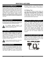
2.1 LOCATION & MOUNTING
Before mounting the cabinet, push the five white nylonmounting studs into the back of the cabinet. Pull all
cables into the cabinet and prepare them for connection
before mounting the circuit board into the back of the
cabinet. Select an installation site that is not easily
accessible to intruders and leave at least 2” around the
panel box to permit adequate ventilation and heat
dissipation. The installation site should be dry and close
to an AC source, ground connection and telephone line
connection.
2.4.1 Battery Test
The control panel conducts a dynamic battery test
under load every 64 seconds. If the battery is
disconnected, if its capacity is too low or if the battery
voltage drops to 10.5 volts or less when there is no
AC, the “Battery Trouble” message will appear in the
Trouble Display (see section 14). At 8.5 volts, the
panel shuts down and all outputs close.
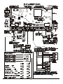
2.2 E ARTH GROUND
2.5 AUXILIARY POWER TERMINALS
Connect the zone and dialer ground terminals from
the control panel to the cabinet and cold water pipe
or grounding rod as per local electrical codes.
The Digiplex Control Panel has two auxiliary
outputs. For details on available output power of
each output, please refer to figure 2.2 on the
following page. You can use the auxiliary power
supply to power the motion detectors, keypads and
other accessories in your security system. A
fuseless circuit protects each auxiliary output
against current overload and automatically shuts
down if the current exceeds 1.1A. Auxiliary power
will resume once the overload condition has
restored.
For maximum lightning protection, use
separate earth grounds for the zone and dialer
grounds as shown in figure 2.2!
2.3 AC POWER
Use a 16.5VAC (50/60Hz) transformer with a minimum
20VA rating to provide sufficient AC power. For
increased power you can use a transformer with a 40VA
rating. For UL Listed systems, you can use Amseco
Models XP-1620 or XP-1640. Do not use any switchcontrolled outlets to power the transformer. Connect the
transformer as shown in figure 2.2.
2.6 TELEPHONE L INE C ONNECTION
Connect the incoming telephone company wires
into the TIP and RING connections of the control
panel. Then run the wires from T1 and R 1 to the
telephone system as shown in figure 2.1.
Do not connect the transformer or the backup battery until all wiring is completed!
2.4 B ACK- UP B ATTERY
In order to provide power during power loss, connect
a 12VDC 7Ah rechargeable acid/lead or gel cell backup battery as shown in figure 2.2. Connect the backup battery after applying AC power. When installing
verify proper polarity, as reversed connections will
- 6-
- 7-
wire smoke detector input. For more information,
refer to sections 2.15.1 and 11.3 of this manual.
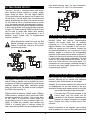
2.7 BELL/S IREN O UTPUT
The BELL+ and BELL- terminals power bells and/or
other warning devices requiring a steady voltage
output during an alarm. The bell output supplies
12VDC upon alarm and can support two 20-watt or two
30-watt sirens. The bell output uses a fuseless circuit
and will automatically shut down if the current exceeds
3A. If the load on the BELL terminals returns to normal
(≤3A), the control panel will re-instate power to the BELL
terminals. When connecting sirens (speakers with builtin siren drivers) please verify correct polarity as shown
in Figure 2.6. Please note that PGM5 is rated at 5A and
can be used to power bells and/or other warning
devices (see Figure 2.3) by programming it as a
bell/siren output. Please refer to Programmable
Outputs in section 11.
2.9 BUS ZONE CONNECTIONS
The DIGI-BUS is a 4-wire communication bus that
provides power and two-way communication
between the control panel and all modules
connected to it. All bus detectors, keypads and
Digiplex Modules are connected to the DIGI-BUS,
which can support up to 95 modules. Connect the
four terminals labeled RED , BLK, GRN and YEL of each
detector, keypad or module to the corresponding
terminals of the control panel as shown in figure 2.2.
Please note that all bus modules can be connected
in a star and/or daisy chain configuration. The final
device on the communication bus should not be
more than 3000 feet from the control panel. For
information on how to assign a detection device to
a zone in the control panel, please refer to Zone
Programming in section 5.
When the bell/siren output isn’t used, the “Bell
Absent” message will appear in the Trouble
Display. To avoid this, connect a 1KΩ resistor
across the bell output.
2.10 KEYPAD ZONE CONNECTIONS
2.8 PROGRAMMABLE O UTPUTS
Each keypad has one traditional hardwired-input
terminal, allowing you to connect one traditional
detector or door contact directly to the keypad.
The Digiplex Control Panel includes five programmable
outputs. When a specific event or condition occurs in
the system, a PGM can be programmed to reset smoke
detectors, activate strobe lights, open/close garage
doors and much more. For details on how to program
the PGMs, refer to section 11.
Example: A door contact located at the entry point of
an establishment can be wired directly to the input
terminal of the entry point keypad instead of wiring the
door contact all the way to the control panel.
PGM1 provides a maximum 100mA output, PGM2 to
PGM4 provide a maximum 50mA output and PGM5
provides a maximum 5A output. If the current draw
on the PGM is to exceed the current output, we
recommend the use of a relay as show in figure 2.4.
PGM1 to PGM4 are normally open outputs and
PGM5 is a normally open or normally closed 5A
relay. Also note that PGM1 can be programmed as 2-
Even with the ATZ feature enabled in the
control panel, only one device can be
connected to the keypad’s hardwired-input
terminal. No tamper recognition on keypad
zones. Keypad zone follows control panel’s EOL
definition.
Devices connected to the keypad’s input terminal
must be assigned to a zone in the control panel and
- 8-
the zone’s parameters must be defined. Please refer to
Zone Programming in section 5 for more information.
The keypad will communicate the status of the zone to
the control panel. The detection device is connected as
shown in figure 2.2.
zone’s parameters must be defined. Please refer to
Zone Programming in section 5 of this manual for
more information. Figure 2.5 demonstrates single
zone (ATZ disabled) hardwire-input terminal
connections recognized by the Digiplex system.
2.11 SINGLE ZONE CONNECTIONS
2.12 DOUBLE ZONE CONNECTIONS
In addition to the DIGI-BUS, the Digiplex Control Panel
includes four hardwired-input terminals for use with
traditional hardwired (non-bus) door contacts, smoke
detectors and/or detectors. ZX8 Zone Expander
Modules are available, which when connected to the
DIGI-BUS will provide eight additional hardwire-input
terminals. The control panel also supports one onboard Expansion Module, the ZX4. The ZX4 will add
four hardwired-input terminals to the control panel
(see section 2.13). Devices connected to hardwiredinput terminals must be assigned to a zone and the
Enabling the ATZ feature (see section 5.7), allows
you to install two detection devices per input
terminal. The ATZ feature is a software-oriented
feature. Therefore, there is no need for extra
modules, simply connect the devices as shown in
figure 2.6 on the following page. Devices connected
to input terminals must be assigned to a zone and
the zone’s parameters must be defined. Please
refer to Zone Programming in section 5 of this
manual for more information.
- 9-
2.13 CONNECTING THE ZX4
The ZX4 is a 4-Zone Expansion Module that connects directly to the control panel through its on-board
EXPANSION connector as shown in figure 2.7. The ZX4 provides four additional hardwired-input terminals.
Detection devices are connected to the ZX4’s terminals in the same way they are connected to the control panel
as shown in figures 2.5 and 2.6. Devices connected to hardwired-input terminals must be assigned to a zone
and the zone’s parameters must be defined. Please refer to Zone Programming in section 5 of this manual.
- 10 -
2.15.2 UL/ULC Installation
2.14 KEYSWITCH C ONNECTIONS
Connect the 4-wire smoke detectors and a relay as
shown in figure 2.10. In the event power is
interrupted, the relay will cause the control panel to
transmit the Global Fire Loop Trouble report if
programmed in section [697]. To reset (unlatch) the
smoke detectors after an alarm, verify that the
negative (-) of the smoke detectors are connected
to a PGM as shown in figure 2.10. Then program
the PGM with the “Smoke Reset” activation event
(see section 11.1 of this manual) to interrupt power
to the smoke detector for four seconds when the
[CLEAR ] and [ENTER] keys are pressed and held for
2 seconds.
Connect the keyswitches to the keypad, control
panel, or Zone Expander Module’s hardwired-input
terminals as shown in figure 2.8. Once a keyswitch is
connected, it must be assigned a keyswitch zone and
its parameters must be defined as described in
Keyswitch Programming (see section 6 of this
manual).
2.15 FIRE C IRCUITS
Connect the smoke detectors used in the security
system using any of the following methods. Smoke
detectors connected to the control panel or zone
expander input terminals must be assigned to a zone
in the control panel and the zone’s parameters must
be defined as a Fire Zone. For more details, refer to
Zone Programming in section 5 of this manual.
2.15.1 Standard Installation
PGM1 can be defined as a 2-wire smoke detector
input (see section 11.3); enabling smoke detectors to
be connected as shown in figure 2.12. Fire Zones
must use a 1KΩ EOL resistor. If there is a line short
or if the smoke detector becomes active, whether the
system is armed or disarmed, the control panel will
generate an alarm. If the line is open, the “Zone
Fault” trouble indication will appear in the Trouble
Display and will transmit the appropriate report code
to the central station (if programmed).
- 11 -
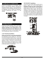
PROGRAMMING METHOD
The Digiplex Control Panel can be programmed using
the Paradox Upload/Download Software for
Windows or manually by using a keypad as
described below. We highly recommend programming
the control panel with the Upload/Download software,
as it greatly simplifies the process and reduces the
potential of data errors.
on an LED Keypad. You turn options ON and
OFF by pressing the corresponding buttons on
the keypad. Press the keys as many times as
you need until all 8 options in the current
section are set. When the options are set, press
the [ENTER] or [p
p ] key to save.
•
Certain sections may require the entry of one or
more Hexadecimal values from 0 to F:
[0] to [9] = values 0 to 9 respectively
[STAY] key = A
[DISARM ] key = D
[FORCE] key = B
[BYP] key = E
[ARM] key = C
[MEM] key = F
3.1 UPLOAD /D OWNLOAD SOFTWARE
Remotely program the Digiplex Control Panels using
the Paradox Upload/Download Software, or perform
on-site programming. Please refer to section 13 for
details on how to set up the control panel to function
with the upload/download software.
•
Certain sections may require the entry of a 3digit Decimal value from 000 to 255.
After entering the required data, the control panel
will save the data and automatically advance to the
next section, or press the [ENTER] key to save
whatever data has been entered and automatically
advance to the next section. Press the [CLEAR] key
to revert to the preceding step, unless you are entering
data, in which case it will erase the current data entry.
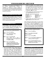
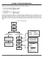
3.2 PROGRAMMING MODE
Use the supplied “Programming Guide” to keep track
of which sections were programmed and how. In
order to program anything in the Digiplex Control
Panel you must enter the programming mode.
To enter the Module Programming Mode:
To enter Control Panel Programming Mode:
Step 1 – Press & Hold [0] key
Step 1 – Press & Hold [0] key
Step 2 – Key in [INSTALLER CODE]
Default is 000000
Step 2 – Key in [INSTALLER CODE]
Default is 000000
Step 3 – Key in section [953]
Step 3 – Key in 3-digit [SECTION ]
Every feature and or option is
programmed into a three-digit section
from [001] to [979].
Step 4 – Key in 8-digit [SERIAL NUMBER] of the
module you wish to program
Step 5 – Key in 3-digit [SECTION ] & required
[DATA ] Refer to installation manual of
desired module for details.
Step 4 – Key in required [DATA ]
The type of data required will be
detailed in the “Programming Guide”
and/or explained in the appropriate
section of this manual.
•
3.3 PROGRAMMING BUS MODULES
Most of the Digiplex Control Panel Options are
programmed using the Feature Select Method,
where each number from 1 to 8 corresponds to a
specific feature or option. Set these options by
turning the number corresponding to the feature
ON or OFF. The option is considered ON when
the number appears within the brackets on the
LCD keypad or when the number is illuminated
The control panel will redirect all programming to the
selected module. To exit the Module Programming
Mode, press the [CLEAR] key as many times as
needed to return to the desired screen. Please note
that a module’s serial number can be located on the
module’s PC board or it may already be recorded in
the module’s Programming Guide.
- 12 -
ACCESS CODES
The Digiplex control panel supports the following
access codes:
• 63 User Access Codes
• 1 System Master Code
• 1 Installer Code.
Access Codes, User Options and User Partition
Assignments. The System Master Code can use
any digits from 0 to 9. The length of the System
Master Code is determined by the Access Code
Length feature (see section 4.2 above).
The System Master Code cannot be set to
less than 4-digits in length.
4.1 Installer Code
Section [800]
{Default: 000000} The Installer Code is used to enter
the control panel’s programming mode, which allows
you to program all the features, options and
commands of the control panel and any modules
connected to the DIGI-BUS. The Installer Code can not
program the User Access Codes. The Installer Code
is six digits in length where each digit can be any
value from 0-9.
4.3.1 System Master Code Reset
Using the Installer Code, enter section [950] to
reset the System Master Code to 123456.
The Installer can program the User Code
Options and Partition Assignment but
cannot program the System Master Code or
the User Access Codes.
Press & Hold [0] + [INSTALLER CODE ] + [800] + New
6-digit [INSTALLER CODE]
4.4 USER O PTIONS
The User Options define how each User Access
Code can arm or disarm the system. Regardless of
these settings, all users can Regular Arm (see
section 14) assigned partitions (see section 4.5 of
this manual) and all users except those with the
Arm Only option (see section 4.4.4) can disarm an
assigned partition. Select one or more of the
options described in the following sub-sections for
each User Access Code as shown in figure 4.1 on
the following page. The System Master Code or a
user with the Master Feature enabled can also
program the User Options using a different method
of programming (see section 14).
4.2 ACCESS C ODE LENGTH
Section [504] – Options [2] & [3]
[2]
Off
Off
On
On
[3]
Off
On
Off
On
Option
4-Digit Access Codes
6-Digit Access Codes
Same as On/On
Flexible Access Codes
Access codes can be between 1 and
6 digits in length. When programming
flexible access codes with less than 6digits, press the [ENTER] key.
When you change the Access Code Length from 4
digits to 6 digits, the control panel will automatically
add the last 2 digits by using the first 2 digits. For
example, if your Access Code is 1234 and you switch
to 6 digits the code will become 123412. When you
change the Access Code Length from 6 digits to 4
digits, the control panel will automatically remove the
last 2 digits.
4.4.1 Master Feature
Sections [802] to [864] – Options [1] & [2]
[1]
Off
Off
On
On
4.3 S YSTEM MASTER CODE
{Default: 123456} With the System Master Code a
user can use any of the available arming methods
with access to all partitions and can program all User
- 13 -
[2]
Off
On
Off
Option
Master Feature Disabled
Master Feature Disabled
Users can create or modify User
Access Codes that have the same
partition assignment.
On Users can create or modify User
Access Codes with the same partition
assignment and program the User
Options & Partition Assignment
(assigns only partitions the Master
Feature Code has access to).
4.4.2 Duress
4.5 USER P ARTITION A SSIGNMENT
Sections [802] to [864] – Option [3]
When a user is forced to arm or disarm their system,
entering a Duress enabled User Access Code (option
[3] on) will arm or disarm the system and, if
programmed, will immediately transmit a silent alert
to the Central Station.
Sections [802] to [864] – Options [1] to [4]
Each of the 63 User Access Codes can be assigned
to one or more partitions. A user can only arm, disarm
and view status of assigned partitions. Select one or
more of the partitions for each User Access Code
as shown in figure 4.1. The System Master Code or
a user with the Master Feature enabled can also
program the User Partition Assignment using a
different method of programming (see section 14).
4.4.3 Bypass Programming
Sections [802] to [864] – Option [4]
The User Access Code with option [4] enabled can
program bypass entries as described in section 14.
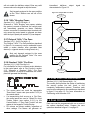
Figure 4.1 - Programming User Parameters
Using the method described below, the Installer can
program the User Code Options and User Code Partition
Assignment but can not program any User Access Codes.
4.4.4 Arm Only
Sections [802] to [864] – Option [5]
The User Access Code with option [5] enabled can
arm assigned partitions but can not disarm any
partitions. The type of arming is determined by the
other User Options selected. Please note that with
the Arm Only option, the user who just armed the
system can cancel arming by re-entering the same
User Access Code during the Exit Delay.
Press and hold
the [0] key
Where sections [802] to [864]
represent User Access Codes
002 to 064.
Key in the
[ INSTALLER CODE]
Key-in [SECTION]
User Code Options
[1]
off
off
on
on
[2]
off
on
off
on
4.4.5 Stay & Instant Arming
User Options
Sections [802] to [864] – Option [6]
The User Access Code with option [6] enabled, can
Stay Arm or Instant Arm (see section 14) assigned
partitions.
Feature Select
Programming
Press the [p] key
User Partition
Assignment
4.4.6 Force Arming
Feature Select
Programming
Sections [802] to [864] - Option [7]
The User Access Code with option [7] enabled will be
able to Force arm assigned partitions as described in
section 14.
Feature
Master Feature Disabled
Master Feature Disabled
User can program access codes
User can program access
codes, options & assignment
[3] Duress
[4] Bypass
[5] Arm only
[6] Stay & Instant
[7] Force
[8] Main Menu Access
*Note: all users can regular arm.
User Code Partition Assignment
[1] User
[2] User
[3] User
[4] User
Code
Code
Code
Code
Has
Has
Has
Has
Access
Access
Access
Access
to
to
to
to
Partition
Partition
Partition
Partition
1
2
3
4
Press [ENTER ] or the [p] key to
save and go to the next section.
4.4.7 User Menu Access Conditions
Sections [802] to [864] - Option [8]
This feature will govern which partitions users have
access to when entering their access codes. With
option [8] on, the control panel will grant access to all
partitions assigned to the User Access Code. With
option [8] off, the control panel will only grant access
to partitions that have been assigned to both the
User Access Code and the keypad.
4.6 MULTIPLE A CTION FEATURE
Section [504] – Option [1]
By enabling option [1] in section [504], users will
remain in the User Menu after entering their access
code. This allows users to perform more than one
action without having to re-enter their access code.
With option [1] off in section [504], the control
panel will exit the User Menu after every action.
- 14 -
ZONE PROGRAMMING
All detection devices, whether connected to the control panel, keypads or zone expander modules must be
assigned to a zone and that zone must be defined as described in this section:
}
}
•
•
Serial # of the Device/Module
Input # of the Device/Module
•
•
•
Zone Definition
Zone Partition Assignment
Zone Options
Zone Numbering
[001] to [048]
Zone Parameters
[101] to [148]
The Zone Numbering feature enables you to individually assign each detection device to any desired zone in the
Digiplex system. Please refer to section 5.1 of this manual for details. The Zone Parameters define the type of zone, the
zone’s partition assignment and how the control panel will react when an alarm condition occurs on that zone (see
sections 5.2 to 5.4). For more information on the installation of devices and modules, please refer to section 2 of this
manual.
Figure 5.1 - Zone Programming
Press & hold the
[0] key
Key-in
[INSTALLER CODE]
Key in 3-digit
[ SECTION ]
Zone Definitions
Zone Numbering
Sections [001] to [048] represent
zones 1 to 48 respectively
Zone Parameters
Sections [101] to [148] represent
zones 1 to 48 respectively
Enter 8-digit
[ SERIAL NUMBER ] of the bus
detection device or of the
module to which a hardwire
device is connected
Zone Definition
First Digit
Enter 3-digit [INPUT NUMBER ] of
module to which device is
connected
NOTE: For motion detectors and
keypads no input # is required
Zone Partition
Assignment
Second Digit
Select
only one
0- Disabled
1- Entry Delay 1
2- Entry Delay 2
3- Entry Delay 3
4- Entry Delay 4
5- Follow
6- Instant
7- 24Hr Buzzer
8- 24Hr Burglary
9- Delayed 24Hr Fire
A- Stand. 24Hr Fire
Zone Partition Assignment
Select one only
1- Zone Assigned to Partition 1
2- Zone Assigned to Partition 2
3- Zone Assigned to Partition 3
4- Zone Assigned to Partition 4
Zone Options
Zone Options
Feature Select
Select one
or more
Press [ENTER ]
- 15 -
[1] Auto Zone Shutdown
[2] Bypass Zone
[3] Stay Zone
[4] Force Zone
[5] [6] Zone Alarm Type
off off Audible Alarm (steady)
off on Audible Alarm (pulsed)
on off Silent Alarm
on on Generates only a report
[7] Intellizone
[8] Delay before transmission
5.2.1 Zone Disabled
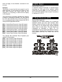
5.1 ZONE NUMBERING
Sections [101] - [148]: First digit = 0
Disables the corresponding zone.
Sections [001] to [048]
The Zone Numbering feature allows you to assign
any detection device in the system, to any of the 48
zones. This feature tells the control panel where the
device is connected and which of the 48 zones is
assigned to that device.
• To assign a bus detector connected to the DIGIBUS, program the detector’s serial number into
the section corresponding to the desired zone
(i.e. zone 34 = section [034]).
• To assign a detection device connected to a
module or control panel’s hardwired-input
terminal. Program the module’s or control
panel’s serial number and the number of the
input to which the device is connected into the
section corresponding to the desired zone. Refer
to the appropriate module’s Installation Manual
for details of its input numbers. Note: an input
number is not required for keypad zones.
5.2.2 Entry Delays 1 to 4
Sections [101] - [148]: First digit = 1 to 4
When an armed zone with the Entry Delay definition
opens, the control panel will not generate an alarm
until the programmed Entry Delay Timer has
elapsed. A zone can be defined with one of four
Entry Delays each with a separate Entry Delay
Timer. To program the Entry Delay Timer, key in the
desired 3-digit delay value (000-255 seconds) into
the corresponding section:
♦ Entry Delay 1 Timer : [230]
♦ Entry Delay 2 Timer : [231]
♦ Entry Delay 3 Timer : [232]
♦ Entry Delay 4 Timer : [233]
Entry Delay zones are commonly used at the
entry/exit points of the protected area (i.e. front/back
door, garage). Using different Entry Delays is useful
when, for example, one entry point requires a longer
delay than the other entry point, or in a partitioned
system where each partition may require a different
Entry Delay .
If PGM1 is defined as a smoke detector
input (see section 11.3), the control
panel will recognize it as input # 255.
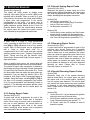
Figure 5.2 - Example of Zone Numbering
Bus Detector A
SN#: 20000125
Bus Detector B
SN#: 20000455
Digiplex
Control Panel
SN#:
00000000
Sections [101] – [148]: First digit = 5
If an armed Follow zone opens, the control panel will
immediately generate an alarm. If an armed Entry
Delay zone (see section 5.2.2) opens before the
Follow zone, the control panel will wait until the end
of the entry delay period before generating an alarm.
If more than one Entry Delay zone opens before the
Follow zone, the control panel will wait until the end
of the first entry delay period before generating an
alarm.
DIGI-BUS
Input Terminals
1
2
3
4
ZX8 Module
SN#: 30000041
2
Input Terminals
3 4 5 6
7
8
Input 8
1
Input 3
Input 2
Hardwired
Device C
5.2.3 Follow Zones
Bus Detector C
SN#: 21000033
Hardwired
Hardwired
Device A
Device B
Zone# Section#
Serial#
Bus Detector A:
1=
[001]
20000125
Bus Detector B:
2=
[002]
20000455
Bus Detector C:
3=
[003]
21000033
Hardwired Device A:4 =
[004]
30000041
Hardwired Device B:5 =
[005]
30000041
Hardwired Device C:6 =
[006]
00000000
5.2.4 Instant Zones
Sections [101] – [148]: First digit = 6
When an armed Instant zone opens, the control
panel immediately generates an alarm. Instant
zones are commonly used for windows, patio doors,
skylights and other perimeter type zones.
Input#
N/A
N/A
N/A
003
008
002
5.2.5 “24Hr” Buzzer Zones
Sections [101] – [148]: First digit = 7
Whenever a “24Hr” Buzzer zone opens, whether the
zone is armed or disarmed, the control panel will set
off the keypad buzzer to indicate the zone was
breached. The control panel will report the alarm, but
5.2 ZONE DEFINITIONS
Select one of the 11 available zone definitions
described below (also refer to figure 5.1).
- 16 -
will not enable the bell/siren output. Enter any valid
access code on the keypad to stop the buzzer.
intermittent
bell/siren
output
demonstrated in Figure 5-3.
Only keypads assigned to the same partition
as the “24HR” Buzzer zone will set off the
buzzer.
signal
as
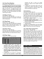
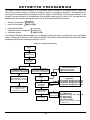
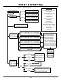
Figure 5.4 - Delayed 24Hr. Fire Zone
Delayed Fire Zone
Triggered
5.2.6 “24Hr” Burglary Zones
Activate bell/siren output & delay
report transmission for 30 seconds.
Sections [101] – [148]: First digit = 8
Whenever a “24Hr” Burglary zone opens, whether
the system is armed or disarmed, the control panel
will immediately generate an alarm. Detection
devices connected to hardwired-input terminals will
only cause the control panel to generate an alarm
after the Input Speed (see section 5.5) has elapsed.
Has the zone
closed within
30 seconds?
Yes
No
Has a 2nd
Delayed Fire
Zone opened in
30 sec.?
5.2.7 Delayed “24Hr.” Fire Zone
Sections [101] – [148]: First digit = 9
The Delayed “24Hr.” Fire Zone definition described
in figure 5.4 is commonly used in residential homes
where a smoke detector often generates false
alarms (i.e. cigarette smoke, burning bread, etc.).
Yes
Latch alarm and transmit
report code as described
in section 5.2.8
No
Any key on
keypad pressed
within 30
seconds?
Note only keypads assigned to the same
partition as the Delayed “24HR” Fire zone
will activate the buzzer.
No
Yes
Yes
Bell/siren silenced.
Delay report
transmission an additional 90 sec.
5.2.8 Standard “24Hr” Fire Zone
No
Sections [101] - [148]: First digit = A
For information on how to connect smoke detectors
to the control panel, refer to Fire Circuits in section
2.15. Whenever a Standard “24Hr.” Fire Zone
opens, whether it is armed or disarmed, the control
panel will generate the following:
Problem
corrected?
Yes
END
Alarm Disabled
5.3 ZONE P ARTITION ASSIGNMENT
§
§
•
Sections [101] - [148]: Second digit = 1-4
The control panel provides the option of partitioning
the security system into two, three, or four
completely independent systems. Therefore, each
zone must be assigned to one partition as described
in figure 5.1 on page 15. For more information on
Partitioning, refer to section 12.6.
The control panel can send the appropriate
“Zone Alarm” report code (see section 9.2.5) to
the central station.
If a tamper/wiring fault occurs on a Fire Zone,
the control panel can send a “Global Fire Loop
Trouble Report (see section 9.2.11) to the
Central Station. A “Zone Fault Trouble” will also
appear in the keypad’s Trouble Display.
Fire alarms are always audible, regardless of
other settings. Fire alarms will generate an
5.4 ZONE O PTIONS
Each zone can be programmed with one or more of
the options described below. Program the zone
options as described in figure 5.1 on page 15.
- 17 -
5.4.1 Auto Zone Shutdown
Sections [101] – [148]: Option [1]
If, in a single armed period, an Auto Zone Shutdown
zone communicates more than the number of alarm
transmissions defined by the Auto Zone Shutdown
Limit, the control panel will no longer generate an
alarm for that zone. To program the Auto Zone
Shutdown Limit, key in the desired 3-digit counter
(000-015) into section [217]. Entering 000 disables
this feature. The Auto Zone Shutdown Limit resets
upon arming the system.
§
activating any bells or sirens (e.g. keypad
indicates an alarm and the system must be
disarmed).
A “Report Only”, will send the report code to the
central station. Unlike a silent alarm, no access
codes are required to cancel the alarm. Fire
Zones cannot be set to “report only”.
5.4.6 Intellizone
Sections [101] – [148]: Option [3]
Only zones with option [3] enabled will be bypassed
when the system is Stay Armed (see section 14 for
details). All other zones will remain activated. Fire
Zones can not be set as Stay Zones.
Sections [101] – [148]: Option [7]
If an alarm condition occurs on a zone with option
[7] enabled, the control panel will trigger the
Intellizone Delay and will seek confirmation of the
alarm before generating an alarm. An alarm will only
be generated if one of the following conditions
occurs during the Intellizone Delay:
(a) An alarm condition occurs on any another
intellizone during the Intellizone Delay.
(b) The zone in alarm has restored and re-occurred
during the Intellizone Delay.
(c) The zone in alarm remains in alarm for the entire
Intellizone Delay.
To program the Intellizone Delay, key in the desired
3-digit delay value (010-255 seconds), into section
[200]. Fire Zones can not be set as Intellizones.
5.4.4 Force Zones
5.4.7 Delay Alarm Transmission
Sections [101] – [148]: Option [4]
Only zones with option [4] enabled can be bypassed
when the system is Force armed (see section 14 for
details). Fire Zones can not be set as Force Zones.
Sections [101] – [148]: Option [8]
When an alarm condition occurs on a zone with
option [8] enabled, the control panel will generate an
alarm but will not report the alarm to the central
station until the end of the Alarm Transmission
Delay. During this period, disarming the system will
cancel any report originating from this zone. To
program the Alarm Transmission Delay, key in the
desired 3-digit delay value (001-255 seconds, 000=
instant) into section [256]. This feature is commonly
used with Entry Delay zones in order to reduce the
occurrence of false alarms created by new users
who may not disarm the system in time.
5.4.2 Bypass Zones
Sections [101] – [148]: Option [2]
Only zones with option [2] enabled can be Manually
Bypassed (see section 14 for details). Fire Zones
can not be bypassed.
5.4.3 Stay Zones
5.4.5 Alarm Types
Sections [101] - [148]: Options [5] & [6]
Options
[5]
[6]
OFF OFF
OFF ON
ON OFF
ON
ON
§
§
§
Zone Alarm Type
Steady Audible Alarm
Pulsed Audible Alarm
Silent Alarm
Generates a report only
A “Steady Audible Alarm” will transmit the
appropriate report code (if programmed) and
generates an alarm providing a steady output for
any bells or sirens connected to the control panel.
A “Pulsed Audible Alarm” will transmit the
appropriate report code and generates an alarm
providing a pulsed output (see figure 5.3 on page
17) for any bells or sirens connected to the
control panel.
A “Silent Alarm” will transmit the appropriate
report code and generates an alarm without
5.5 INPUT S PEED
Sections [201] to [216]: 000-255 X 20msec.
{Default: 600mS} The Input Speed defines how
quickly the control panel will respond to an open zone
detected on any hardwired-input terminal. The control
panel will not display and/or respond to an open zone
until the programmed Input Speed elapses. All other
zone definitions and options do not come into effect
until the Input Speed has elapsed. The Input Speed
- 18 -
does not apply to bus detectors connected to the
DIGI-BUS.
5.6 EOL ZONES
Section [504]: Option [7]
If detection devices connected to hardwired-input
terminals use 1KΩ end of line resistors, enable
option [7] in section [504]. For more information on
the use of EOL resistors, refer to Input Connections
in sections 2.11 & 2.12.
Example:
The system is armed and the zone speed is set for
600m seconds. A zone opens and closes in less
than 600m seconds, the control panel will not
respond (i.e. no reporting, no alarm and no display
on the keypad).
This prevents any momentary glitches from causing
an alarm or unnecessary reporting. The Input Speed
for each input terminal can be set from 20ms to
5.1s, by programming the desired value (001-255 X
20ms) into the appropriate section.
[201]
[202]
[203]
[204]
[205]
[206]
[207]
[208]
5.7 ZONE DOUBLING (ATZ)
Section [504]: Option [8]
Enabling the ATZ feature allows you to install two
detection devices per zone input terminal. Each
detection device will have its own zone, displaying
zone status on the keypad and sending separate
alarm codes for each zone. The extra zones are
recognized as described in figure 5.5. For
information on how to connect the detection devices,
please refer to Double Zone Connections in section
2.12. Please note that Fire Zones can not be
doubled.
Control Panel Terminal 1/ Input 001 speed
Control Panel Terminal 2/ Input 002 speed
Control Panel Terminal 3/ Input 003 speed
Control Panel Terminal 4/ Input 004 speed
Control Panel Doubler 1/ Input 005 speed
Control Panel Doubler 2/ Input 006 speed
Control Panel Doubler 3/ Input 007 speed
Control Panel Doubler 4/ Input 008 speed
The optional ZX4 On-Board Zone Expander (see
section 2.13 for details):
[209] ZX4 Terminal 1/Input 009 speed
[210] ZX4 Terminal 2/Input 010 speed
[211] ZX4 Terminal 3/Input 011 speed
[212] ZX4 Terminal 4/Input 012 speed
[213] ZX4 Doubler 1/Input 013 speed
[214] ZX4 Doubler 2/Input 014 speed
[215] ZX4 Doubler 3/Input 015 speed
[216] ZX4 Doubler 4/Input 016 speed
- 19 -
KEYSWITCH PROGRAMMING
The Digiplex Control Panel can support up to 8 keyswitch zones in addition to 48 standard zones. A keyswitch
allows a user to arm or disarm a system by pressing a button or by toggling a keyswitch. The keyswitches are
connected to the hardwired-input terminals of either the Digiplex Control Panel, Zone Expander Modules or the
Keypad. For more information on the installation of keyswitches, please refer to in section 2.14. Keyswitches must
be assigned to a keyswitch zone and that zone must be defined as described in this section:
Keyswitch
• Serial # of the Module Numbering
• Input # of the Module
[049] to [056]
}
•
•
•
Keyswitch Definitions
Keyswitch Partition Assignment
Keyswitch Options
}
Keyswitch
Parameters
[149] to [156]
The Keyswitch Numbering feature enables you to individually assign each input to any keyswitch zone in the Digiplex
system. Please refer to section 6.1 of this manual for details. The Keyswitch Parameters define the keyswitch’s partition
assignment and its arming method (see sections 6.2 to 6.4).
Figure 6.1 - Keyswitch Programming
Press & hold the
[0] key
Key-in
[INSTALLER CODE]
Key in 3-digit
[ SECTION ]
Keyswitch Numbering
Sections[049] to [056] represent
keyswitches 1 to 8 respectively
Enter 8-digit
[ SERIAL NUMBER ] of module to
which keyswitch is connected
Keyswitch Parameters
Sections [149] to [156] represent
keyswitches 1 to 8 respectively
2- Maintained Keyswitch
Select
only one
Keyswitch Definition
First Digit
Keyswitch Partition
Assignment
Second Digit
Enter 3-digit [INPUT NUMBER ]
of module to which
keyswitch is connected
Keyswitch Definitions
1- Momentary Keyswitch
Keyswitch Options
Feature Select
Press [ENTER ]
Select one only
Set the [5] key
on/off and select
one arming option
1234-
Keyswitch Partition
Assignment
Keyswitch Assigned to
Keyswitch Assigned to
Keyswitch Assigned to
Keyswitch Assigned to
Partition
Partition
Partition
Partition
Keyswitch Options
[1] to [4]
Future Use
[5] On = Arm Only Off = Arm/Disarm
[6] * Stay Arming
[7] * Away Arming
[8] * Instant Arming
*Select one only; if all are off, defaults
to regular arming.
- 20 -
1
2
3
4
6.2.3 Maintained Keyswitch
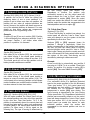
6.1 KEYSWITCH NUMBERING
Sections [149] – [156]: First digit = 2
To arm a partition using the Maintained Keyswitch,
turn the switch from the “on” to the “off” position. To
disarm a partition set the keyswitch in the “on”
position. In the case of an “Arm Only” option, the
control panel will not perform any action when the
switch is in the “on” position. The selected
Keyswitch Option (see section 6.4) determines the
type of arming.
Sections [049] to [056]
The Keyswitch Numbering feature allows you to
assign any hardwired-input in the system, to any of
the 8 keyswitch zones in the Digiplex Control Panel.
This feature tells the control panel where the
keyswitch is connected and which of the 8 keyswitch
zones is assigned to that keyswitch. To assign a
keyswitch connected to a hard-wired input terminal,
program the module’s serial number and the number
of the input to which the keyswitch is connected, into
the section corresponding to the desired keyswitch
zone (see figure 6.2).
6.3 KEYSWITCH P ARTITION
ASSIGNMENT
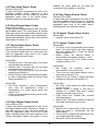
Figure 6.2 - Example of Keyswitch Numbering
Digiplex Control Panel
SN#: 000000A2
Input Terminals
2
3
DIGI -BUS
4
Zone Expander Module
SN#: 30000041
1
Input Terminals
3 4 5 6 7
Input 2
Keyswitch A
2
Keyswitch B
Keyswitch
Zone # Section
Keyswitch A:
1=
[049]
Keyswitch B:
2=
[050]
Keyswitch C:
3=
[051]
6.4 KEYSWITCH O PTIONS
8
Input 6
Input 1
1
Sections [149] to [156]: Second digit = 1 to 4
The control panel provides the option of partitioning
the security system into two, three, or four
completely independent systems. Therefore, each
keyswitch must be assigned to one partition as
described in figure 6.1 on page 20. For more
information on Partitioning, refer to section 12.6.
Each keyswitch zone can be programmed with one or
more of the options described below. Program the
zone options as described in figure 6.1 on page 20.
Keyswitch C
Serial# Input#
000000A2 001
30000041 002
30000041 006
6.4.1 Arm/Disarm Option (Keyswitch)
Sections [149] to [156]:
[5] ON = Arm Only
[5] OFF = Arm & Disarm
Please note that only one of the arming
options (Stay, Force, Instant, and Regular)
can be selected.
6.2 KEYSWITCH D EFINITIONS
Select one of the 2 available keyswitch definitions
described below (see figure 6.1 on page 20).
6.4.2 Stay Arming (Keyswitch)
6.2.1 Keyswitch Disabled
Sections [149] to [156]: Option [6]
Activating the keyswitch will bypass any zones
defined as Stay Zones (see section 5.4.3) in the
selected partition. All other zones will remain
activated. For more information on Stay Arming,
refer to section 14.
Sections [149] – [156]: First digit = 0
Disables keyswitch input.
6.2.2 Momentary Keyswitch
Sections [149] – [156]: First digit = 1
To arm a partition using the Momentary Keyswitch,
turn on the keyswitch for approximately three
seconds then turn it off. Repeating this sequence will
disarm the system. The selected Keyswitch Option
(see section 6.4) determines the type of arming.
6.4.3 Force Arming (Keyswitch)
Sections [149] to [156]: Option [7]
Activating the keyswitch will arm the selected
partition, bypassing any open zones defined as
- 21 -
Force Zones (see section 5.4.4) at the time of
arming. For more information on Force Arming, refer
to section 14.
6.4.5 Regular Arming (Keyswitch)
[149] to [156]: Option [6] to [8]
When options [6] to [8] are off, the keyswitch
arming option will default to Regular Arming (see
section 14).
6.4.4 Instant Arming (Keyswitch)
Sections [149] – [156]: Option [8]
This option is identical to Stay Arming except that all
armed zones will become Instant Zones (see section
5.2.4). For more information on Instant Arming, refer
to section 14.
- 22 -
ARMING & DISARMING OPTIONS
the Auto Arming Option (see section 7.6).
Regardless of whether the partition was
successfully armed or not, the control panel will
always transmit the “Late to Close” report code
programmed in section [618]. Since the control
panel can enable this feature for each individual
partition, select the section that corresponds to the
desired partition and turn on option [5].
7.1 ARMING F OLLOWS P ARTITION
Sections [505], [509], [513], [517]: Options [1] to [4]
A partition can be set to follow the arming and
disarming status of one or more partitions. If a
partition is set to follow more than one partition, the
partition will arm when all selected partitions are
armed. However, the partition will disarm as soon as
one of the selected partitions is disarmed. For more
details on how these options are programmed,
please refer to the Programming Guide.
7.4.1 Auto Arm Timer
Sections [271] to [274]
If Timed Auto-Arming is enabled (see above), the
control panel will send the “Late to Close” report
code and attempt to arm the system at the time
specified by the Auto-Arm Timer.
Example:
If options [2] and [3] are on in section [505], Partition
1 will automatically arm whenever partitions 2 and 3
are armed. Partition 1 will disarm when either
partition 2 or partition 3 is disarmed.
Sections [271] to [274] represent timers for
partitions 1 through 4 respectively. Select the
section corresponding to the partition and program
the time you wish the control panel to arm the
selected partition and/or send the “Late to Close”
report code. Please note that the control panel will
enter a 60-second Exit Delay period before arming
the system. At this point, Auto-Arming can be
cancelled by entering a valid access code.
7.2 NO A RMING O N B ATTERY F AIL
Section [503]: Option [8]
With option [8] on in section [503], the control panel
can restrict arming if the control panel detects a
battery loss or if the battery voltage is less than 10.5.
The control panel will not arm any partition until all
battery trouble conditions are rectified.
Example:
A user would like to automatically arm partition 2
everyday at 6:15PM. To do so, enable “Timed Auto
Arming” for partition 2 by turning on option [5] in
section [509]. Then enter 18:15 in section [272].
7.3 NO A RMING O N T AMPER
Section [501]: Option [8]
With option [8] on in section [501], the control panel
can restrict arming if the control panel detects a
tamper on a zone or module (see section 9.2.8). The
control panel will not arm any partition until all tamper
trouble conditions are rectified and the Installer Code
has been entered to clear the troubles.
7.5 NO MOVEMENT A UTO A RMING
Sections [505], [509], [513], [517]: Option [6]
If no movement occurs in a partition’s protected
area for the period specified by the No Movement
Timer (see section 7.5.1), the control panel will
automatically arm that partition. The control panel
will transmit the “no movement” report code
programmed in section [618] upon arming. The
type of arming is determined by the Auto Arming
Option (see section 7.6). Regardless of whether the
partition was successfully armed or not, the control
panel will always transmit the “Late to Close” report
code (see section 9.2.2 of this manual). As the
control panel can enable this feature for each
individual partition, select the section that
corresponds to the desired partition and turn on
option [6].
7.4 TIMED AUTO A RMING
Option [5] - Sections [505], [509], [513], [517]
With this option enabled, the control panel will arm
the selected partition every day at the time specified
by the Auto Arm Timer (see section 7.4.1). If the
partition is automatically armed, the control panel will
transmit the “auto arming” report code programmed
in section [618]. If the control panel cannot arm the
partition (i.e. open zone), it will try again on the
following day. The type of arming is determined by
- 23 -
Option [4] ON = Press and hold the [FORCE] key for
2 seconds to Force Arm (see section 14)
7.5.1 No Movement Timer
Sections [222] to [225]: 001-255 X 15min.
If No Movement Auto-Arming is enabled (see section
7.5), the control panel send the “No Movement”
report code and attempt to arm the system at the
time specified by the No Movement Timer.
Option [5] ON = Press and hold the [DISARM] key for
2 seconds to Disarm a Stay or Instant armed
partition (see section 14)
Option [6] ON = Press and hold the [BYP ] key for 2
seconds to perform Bypass Programming (see
section 14).
If No Movement Auto-Arming is disabled, the control
panel will still send the “No Movement” report code at
the time specified by the No Movement Timer.
Option [7] ON = Press and hold the [7] key for 2
seconds to access the Event Display.
Sections [222] to [225] represent timers for partitions
1 through 4 respectively. Select the section
corresponding to the desired partition and program
the interval of time (001-255 x15 minutes,
000=disabled) without movement you wish the
control panel to wait before arming and/or sending
the “No Movement” report code.
7.8 EXIT D ELAY
Sections [226] to [229]: 001-255 seconds
The Exit Delay determines the amount of time a
user has to leave the protected area before the
control panel arms the partition. Program the Exit
Delay from 001 to 255 seconds (000=60 seconds),
where sections [226] to [229] represent partitions 1
through 4 respectively. The Exit Delay applies to all
zones in the selected partition except 24Hr. Zones.
Example:
A user would like to arm partition 1 whenever there is
no movement for a period of 4 hours. First, enable the
"Auto Arm on No Movement" feature for partition 1 by
turning on option [6] in section [505]. Then in section
[222] enter 016 (16x15min. = 240min. = 4 hours).
7.8.1 Exit Delay Termination
Sections [505], [509], [513], [517]: Option [8]
The control panel can reduce the Exit Delay to 5
seconds when an Entry Delay zone (see section 5.2.2)
is opened and closed during the Exit Delay. As the
control panel can enable this feature for each individual
partition, select the section that corresponds to the
desired partition and turn on option [8].
7.6 AUTO ARMING O PTIONS
Section [505], [509], [513], [517]: Option [7]
When using the auto arming features (see sections
7.4 and 7.5), the control panel can Force Arm or Stay
Arm the selected partition. In the section
corresponding to the desired partition set option [7]:
Option [7] ON = Stay Arming (see section 14)
OFF = Force Arming (see section 14)
Example:
A user arms a partition with an “Exit Delay” of 45
seconds. After 15 seconds, the user leaves the
protected area through the front door (Entry Delay
zone). When the door closes, the control panel will
reduce the “Exit Delay” from 30 seconds to 5 seconds.
7.7 ONE-TOUCH FEATURES
[508], [512], [516], [520]: Options [1] to [6]
The One-Touch features allow users to arm or
disarm a partition without having to enter any access
codes. As the control panel can enable the Quick
Arming features for each individual partition. Select
the section that corresponds to the desired partition
and turn the desired options on or off as listed below.
7.8.2 No Exit Delay on Remote Arm
[508], [512], [516], [520]: Option [8]
When using the Impulse Wireless Module, the
control panel will cancel the Exit Delay and
immediately arm the system when a user has
activated arming using a remote control.
Option [1] ON = Press and hold the [ARM] key for 2
seconds to Regular Arm (see section 14)
7.9 KEYPAD LOCK-OUT F EATURE
Option [2] ON = Press and hold the [STAY] key for 2
seconds to Stay Arm (see section 14)
Option [3] ON = Press and hold the [5] key for 2
seconds to Instant Arm (see section 14)
- 24 -
Sections [220] & [221]
If a consecutive number of invalid codes are entered
into the keypad, the control panel can be set to
lockout access from a keypad for a specified period.
Program the number of consecutive invalid codes
from 001 to 255 (000=disabled) into section [220].
Program the duration of the keypad lockout from 001
to 255 minutes into section [221]. Although,
programming 000 into section [221] will not lockout the
keypad, but the control panel will transmit the “keypad
lockout” report code programmed in section [689].
seconds of the 60-second period, the bell or siren will
emit three half-second squawks at 1-second intervals.
Turning off option [3] will disable this feature.
Option [4] ON – BELL SQUAWK DURING EXIT DELAY
The bell or siren will emit half-second squawks at 1second intervals during the Exit Delay period.
During the final 10 seconds of the Exit Delay, the
bell or siren will emit three half-second squawks at
1-second intervals. Turning off option [4] will
disable this feature.
7.10 MAXIMUM B YPASS ENTRIES
Section [238] to [241]: 001-255
Sections [238] to [241] represent Maximum Bypass
Entries for partitions 1 through 4 respectively. Select
the section corresponding to the desired partition and
enter any value between 001 and 255 (000=no limit)
to determine the maximum number of zones that can
be bypassed in a selected partition.
Option [5] ON – BELL SQUAWK DURING ENTRY DELAY
The bell or siren will emit half-second squawks at 1second intervals during the Entry Delay period.
Turning off option [5] will disable this feature.
Option [6] ON – BELL SQUAWK ON REMOTE ARMING
When using the Impulse Wireless Module, the
bell or siren will emit a half-second “squawk” upon
arming or disarming with a remote control.
Example:
Section [238] is programmed with 010. When Bypass
Programming (see section 14), the control panel will
not let the user bypass more than 10 zones in
partition 1.
7.13 RING-B ACK
[507], [511], [515], [519]: Options [7] & [8]
After disarming the system, the control panel can
warn the user that there has been an alarm and
that it may be dangerous to enter by having the
keypad “beep” 10 times and/or by squawking the
bell 10 times. The user should leave immediately
and contact the central station from a secure
location. As the control panel can enable the RingBack features for each individual partition, select
the section that corresponds to the desired partition
and turn on the desired option as listed below.
7.11 DISPLAY “B YPASS” IF A RMED
Section [504]: Option [5]
When enabled (option [5] on), the keypad will not
display that there are bypassed zones when the
system is armed.
7.12 BELL S QUAWK
Options [1] to [6] – [507], [511], [515], & [519]
As the control panel can enable the Bell Squawk
features for each individual partition, select the
section that corresponds to the desired partition and
turn on the desired option as listed below.
Option [7] ON = Bell Squawk Ring-Back Enabled
Option [8] ON = Keypad Ring-Back Enabled
7.14 SWITCH TO STAY ARMING
Option [1] ON – BELL SQUAWK UPON DISARMING
The bell or siren will emit two half-second “squawks”
upon disarming. Turn off option [1] to disable this feature.
If no Entry Delay zone is opened and closed during
the Exit Delay after Regular Arming a partition, the
control panel can switch from Regular Arming to Stay
Arming. As the control panel can enable Switch to
Stay Arming for each individual partition, select the
section that corresponds to the desired partition and
turn on the corresponding option as listed below.
Partition 1 = Option [1] – Section [505]
Partition 2 = Option [2] – Section [509]
Partition 3 = Option [3] – Section [513]
Partition 4 = Option [4] – Section [517]
Option [2] ON – BELL SQUAWK UPON ARMING
The bell or siren will emit a half-second “squawk” upon
arming. Turning off option [2] will disable this feature.
Option [3] ON – BELL SQUAWK ON AUTO ARM
The bell or siren will emit half-second squawks at 1second intervals during the 60-seconds before a
partition automatically arms itself. During the final 10
- 25 -
ALARM OPTIONS
is the amount of time after Bell Cut-off the control
panel will wait before re-verifying the zone status.
8.1 BELL/ALARM O UTPUT
Section [500]: Options [5] to [8]
When a partition generates an alarm, the control
panel can toggle the onboard “BELL/ ALARM” output
enabling any bells or sirens connected to it. As the
control panel can enable this feature for each
individual partition, in section [500] turn on the option
that corresponds to the desired partition, where
options [5] to [8] represent partitions 1 through 4
respectively.
8.3 T AMPER RECOGNITION O PTIONS
Section [501]: Options [5] & [6]
If a tamper or wire fault occurs in an armed
partition, regardless of the Tamper Recognition
Options, the control panel will always generate an
alarm, unless Tamper Recognition has been
disabled as described below. Alarms will be silent
or audible depending on individual zone settings.
8.2 BELL C UT-O FF T IMER
Sections [234] to [237]: 001-255 minutes
After an audible alarm, the bell or siren will stop upon
disarming of the partition or when the Bell Cut-Off
Timer has elapsed. As the control panel can set a
Bell Cut-Off Timer for each individual partition, select
the section corresponding to the desired partition and
enter any value between 001 and 255 minutes
(000=5 minutes).
8.2.1 No Bell Cut-Off on Fire Alarm
Section [502]: Option [8]
The control panel can disable the Bell Cut-Off Timer
when alarms generated from zones defined as
Standard or Delayed Fire Zones (see section 5.2)
occur. The bell/siren output will remain enabled until
a user cancels the partition in alarm.
If a tamper or wire fault occurs in a disarmed
partition, the control panel will generate an incident
depending on the following settings:
[5] OFF / [6] OFF - TAMPER RECOGNITION DISABLED
The control panel will not perform any action other
than generate a standard alarm when a tamper or
wire fault occurs in an armed. If the system is
disarmed, the control panel will display the zone as
open in the keypad display but will not generate an
alarm or trouble. This option is not permitted on UL
systems.
[5] OFF / [6] ON - SILENT ALARM
Same as “Trouble Only”, but it will also generate a
silent alarm (no bells or sirens).
[5] ON / [6] OFF - TROUBLE ONLY
When a tamper wiring failure occurs, the “Zone
Fault” trouble will appear in the keypad’s Trouble
Display and the control panel will transmit the
appropriate report code (see section 9.2).
8.2.2 Recycle Alarm
Sections [242] to [249]
Once the Bell Cut-Off Timer has elapsed and after
the Recycle Delay has elapsed, the Recycle Alarm
feature will re-verify the zone status and if there are
any open zones, the control panel will generate
another alarm.
[5] ON / [6] ON - AUDIBLE ALARM
Same as “Trouble Only”, except it will also generate
an audible alarm.
8.3.1 Tamper Bypass Options
In the section corresponding to the desired partition,
program the number of times (001-255, 000=no limit)
in one armed period you wish the control panel to reverify the zone status after bell cut-off. Where sections
[242] to [245] represent partitions 1 through 4.
Section [501] - Option [7]
With option [7] enabled in section [501], Tamper
Recognition follows the zone bypass definition. This
means the control panel will not perform any action
if a tamper or wire fault occurs on a bypassed zone.
With option [7] disabled, the Tamper Recognition
ignores the bypass definition. This means the
control panel will generate an incident (see Tamper
In the section corresponding to the desired partition,
program the Recycle Delay from 001-255 minutes
(000=disabled). Where sections [246] to [249]
represent partitions 1 through 4. The Recycle Delay
- 26 -
Recognition) if a tamper or wire fault occurs on a
bypassed zone.
Option [4] ON = Panic 1 – Silent
OFF = Panic 1 – Audible
Option [5] ON = Panic 2 – Silent
OFF = Panic 2 – Audible
8.4 KEYPAD P ANIC OPTIONS
Sections [506], [510], [514], [518] - Options [1] to [6]
As the control panel can enable Keypad Panic
Options for each individual partition, select the
section that corresponds to the desired partition and
set options [1] through [6] on/off to obtain the desired
options as described below.
Option [6] ON = Panic 3 – Silent
OFF = Panic 3 – Pulsed (Fire)
Silent operation:
The control panel emits a single confirmation beep
and transmits the appropriate report code (see
section 9.2.5) to the central station.
Option [1] ON – PANIC 1
Pressing the [1] & [3] keys simultaneously on the
keypad for 2 seconds will generate a silent or audible
alarm as defined by option [4].
Audible operation:
The alarm output (bell/siren) activates until a user
cancels the alarm with a valid User Access Code or
when the Bell Cut-Off Timer elapses (see section 8.2).
Option [2] ON – PANIC 2
Pressing the [4] & [6] keys simultaneously on the
keypad for 2 seconds will generate a silent or audible
alarm as defined by option [5].
Fire operation:
Same as audible operation, except that the
bell/siren output will be pulsed as shown in figure
5.3 on page 17.
Option [3] ON – PANIC 3
Pressing the [7] & [9] keys simultaneously on the
keypad for 2 seconds will generate a silent or audible
alarm as defined by option [6].
- 27 -
EVENT REPORTING
Figure 9.1 - Event Reporting
Dialing Enabled/Disabled
Option [3] - Section [521]
Related Features
Partition 1
Reporting Account Number 1
3 or 4 digits (0-F) inSection [551]
Partition 2
Reporting Account Number 2
3 or 4 digits (0-F) inSection [552]
Partition 3
Reporting Account Number 3
3 or 4 digits (0-F) inSection [553]
Partition 4
Reporting Account Number 4
3 or 4 digits (0-F) inSection [554]
Reporting Account
Numbers
Delay Before Alarm Transmission
Section [256]
Pager Format Delay Transmission
Section [259]
Recent Closing Delay
Section [219]
Power Failure Report Delay
Section [260]
Auto Test Report
Sections [261] & [270]
Report Disarm Options - Option [7]
Section [506], [510], [514], [518]
Central Station Telephone
Numbers 1 through 4
32 digits Sections [561] to [564]
Report Zone Restore Options - Option [8]
Section [522]
Alternate Dial
Option [6] - Section [522]
Event Call Direction
Defines which Central
Station Telephone
Numbers each specific
group of events will be
reported to.
Dialing sequences forArm/Disarm Report Codes
Partition 1 =Section [523] Partition 3 = Section [529]
Partition 2 =Section [526] Partition 4 = Section [532]
Dialing sequences forAlarm/Restore Report Codes
Partition 1 =Section [524] Partition 3 = Section [530]
Partition 2 =Section [527] Partition 4 = Section [533]
Dialing sequences forTamper/Restore Report Codes
Partition 1 =Section [525] Partition 3 = Section [531]
Partition 2 =Section [528] Partition 4 = Section [534]
Dialing sequence forTrouble/Restore Report Codes
Section [535]
[1] =
[2] =
[3] =
[4] =
[5] =
[6] =
[7] =
[8] =
For each section (dialing sequence) you
can enable up to 4 central station telephone
numbers and 1 of four back-up telephone
numbers. The numbers are dialed
sequentially from 1 to 4 followed by the
back-up number. Continuing this sequence
until each number has been dialed at least
once.
Dialing sequence forSystem Special Report Codes
Section [536]
[0]
Ademco Slow
Pulse
[2]
Sescoa
Reporting Formats
Section [550]
1st digit = CSTN#1
2nd digit = CSTN#2
3rd digit = CSTN#3
4 th digit = CSTN#4
CSTN = Central Station
Telephone Number
[1]
Silent Knight Fast
Call Central Telephone 1
Call Central Telephone 2
Call Central Telephone 3
Call Central Telephone 4
Backup on Telephone 1
Backup on Telephone 2
Backup on Telephone 3
Backup on Telephone 4
Program 2-digit (00-FF)
report codes into sections
[600] to [702] where each
section represents up to 4
events in the system.
Maximum Dialing
Attempts
Section [257]
Delay Between
Dialing Attempts
Section [258]
[3]
Ademco Express
DTMF
(Tone)
[7]
Pager
[5]
Ademco Contact I.D.
[6]
SIA FSK
- 28 -
Sections [790] to [795]
Manual & Automatic programming of
report codes, please refer to sections
9.5.3, 9.5.4 and 9.13 for details
9.2.2 Special Arming Report Codes
9.1 REPORTING E NABLED
Sections [618] to [619]
Whenever the system is armed using one of the
special arming features listed below, the control panel
can send the appropriate report code to the central
station, identifying how the system was armed.
Section [521]: Option [3]
This option will either enable or disable event
reporting. With option [3] on in section [521] event
reporting will be enabled. When an event (e.g. open
zone) occurs in the system, the control panel verifies if
a report code was programmed in the section
corresponding to the event. If a report code is
programmed, the control panel will dial the central
station telephone number defined by the Event Call
Direction feature. When the central station answers,
the control panel will transmit the system account
code, followed by the programmed report code.
Section [618]
§ Auto Arming: see section 7.4
§ PC Arming: system armed using PC software
§ Late to Close: see section 7.4
§ No Movement: see section 7.5
Section [619]
§ Partial Arming: when partitions are Stay Armed,
Instant Armed or armed with bypassed zones
§ Quick Arming: partitions armed using any of the
One-Touch Arming features (see section 7.7)
9.2 REPORT C ODES
A report code is a 2-digit or 1-digit hexadecimal
value, consisting of digits from 0 to F. Each section
from [600] to [702] represents a set of four specific
events. Each of these events can be programmed
with a 1-digit or 2-digit report code. For a
comprehensive list of the events and their relevant
sections, please refer to the “Digiplex Programming
Guide”. Please note that only the Ademco Slow,
Silent Knight, Sescoa and Pager Formats support 1digit report codes.
9.2.3 Disarming Report Codes
Sections [620] to [637]
A report code can be programmed for each of the
sixty-four User Access Codes and 8 keyswitch
zones. Whenever an access code or keyswitch is
used to disarm one or more partitions, the control
panel can send the appropriate report code to the
central station, identifying which access code or
keyswitch was used to disarm the partition(s). The
control panel can transmit the report codes every
time a partition is disarmed or only when disarmed
following an alarm. Please refer to Disarm
Reporting Options in section 9.10.
When a specific event occurs, the control panel will
send the programmed report code to the central station.
The method of report code transmission is defined by
the following two items: Reporting Formats (see section
9.5) and Event Call Direction (see section 9.6). These
two items define how and where the report codes are
transmitted. If you are using the Ademco CID or SIA
formats an Auto Report Code Programming feature is
available. Using this feature, sections [600] to [702] do
not have to be manually programmed (see section
9.13). For more information, see Reporting Formats in
section 9.5. The following sub-sections provide a brief
description of the events that the control panel can
report.
9.2.4 Special Disarming Report Codes
Section [638]
Whenever using one of the special disarming
features listed below, the control panel can send
the report code to the central station, identifying
how the system was disarmed. The control panel
can transmit the report codes every time a partition
is disarmed or only when disarmed following an
alarm. Please refer to Disarm Reporting Options in
section 9.10.
Section [638]
§ Cancel Auto-Arm: if a user disarms the partition
during the auto-arm 60-second delay
§ Quick Disarm: partitions armed using the OneTouch Disarming feature (see section 7.7)
§ PC Disarm: when the PC software is used to
disarm the system
9.2.1 Arming Report Codes
Sections [600] to [617]
A report code can be programmed for each of the
sixty-four User Access Codes and 8 keyswitch
zones. When using an access code or keyswitch to
arm one or more partitions, the control panel can
send the appropriate report code to the central
station, identifying which access code or keyswitch
zone was used to arm the partition(s).
- 29 -
disabled, the control panel will not report the
occurrence of any tampers or wire faults.
9.2.5 Zone Alarm Report Codes
Sections [639] to [650]
A report code can be programmed for each of the
forty-eight available zones. Whenever a zone
generates an alarm, the control panel can send the
appropriate report code to the central station,
identifying which zone generated an alarm.
9.2.9 Zone Tamper Restore Codes
Sections [677] to [688]
A report code can be programmed for each of the
forty-eight available zones. Whenever a tampered
zone is restored, the control panel can send the
appropriate report code to the central station,
identifying which zone has been restored.
9.2.6 Zone Restore Report Codes
Sections [651] to [662]
A report code can be programmed for each of the fortyeight available zones. The control panel can transmit
these report codes to the central station when the zone
closes after generating an alarm or once the bell has cutoff after alarm generation. Please refer to Zone Restore
Report Options in section 9.11.
9.2.10 Special Tamper Report Codes
Section [689]
§ Keypad Lockout: (see section 7.9)
9.2.11 System Trouble Codes
Section [690]
§ AC Failure: no AC input detected on the control
panel. The control panel can delay reporting
this event, please refer to Power Fail Report
Delay in section 9.9.
§ Battery Failure: the back-up battery is
disconnected or the battery voltage is ≤ 10.5V
§ Auxiliary Supply: one of the auxiliary power
supplies current is ≥1.1A
9.2.7 Special Alarm Report Codes
Sections [663] to [664]
Whenever the system generates an alarm due to one
of the conditions listed below, the control panel can
send the appropriate report code to the central
station, identifying the type of alarm.
Section [663]
§ Emergency Panic: if the panic keys [1] & [3] have
been pressed (see section 8.4)
§ Auxiliary Panic: if the panic keys [4] & [6] have
been pressed (see section 8.4)
§ Fire Panic: if the panic keys [7] & [9] have been
pressed (see section 8.4)
§ Recent Closing: if after having armed the system,
an alarm is generated within the Recent Close
Delay (see section 9.7)
Section [691]
§ Bell Output: the bell/siren output is
disconnected or the current is ≥3A
§ Timer Loss: the control panel detects a loss in
panel time (see section 12.8)
§ Global Fire Loop Trouble: a tamper has been
detected on a fire zone (see section 5.2)
Section [692]
§ Bus Fault: a bus module has been removed
from the DIGI-BUS.
§ Module Tamper: a tamper or wire fault is
detected on a module other than a motion
detector connected to the DIGI-BUS
§ ROM Check Error: Problem with on-board
Read-Only Memory
§ Module TLM: TLM failure detected on back-up
voice dialer connected to the DIGI-BUS
Section [664]
§ Auto Zone Shutdown: a zone communicates
more than the programmed number of
transmissions in a single armed period (see
section 5.4.1)
§ Duress: a Duress enabled access code is keyedin (see section 4.4.2).
9.2.8 Zone Tamper Report Codes
Section [665] to [676]
A report code can be programmed for each of the
forty-eight available zones. Whenever a tamper or
wire fault occurs on a zone, the control panel can
send the appropriate report code to the central
station, identifying which zone was tampered. If the
Tamper Recognition Options (see section 8.3) are
Section [693]
§ Module Fail to Communicate: A Back-up voice
dialer has failed to communicate with the
central station
§ Printer Fault: the Digiprint has detected an error
(see Digiprint Manual for details).
§ Module AC Failure: Bus Power Supply
- 30 -
§
Module Battery Failure: Bus Power Supply
appropriate report code to the central station,
identifying the type of system occurrence.
Section [694]
§ Module Auxiliary Failure: Bus Power Supply
§ Wireless Module Battery Low
§ Wireless Module Supervision
Section [701]
§ Cold Start: the control panel was completely
shutdown (total power loss) and the control
panel was re-started
§ Warm Start: the control panel performs a reset
due to any sudden problem other than power
loss
§ Test Report: a test report has been generated
automatically (see section 9.8)
Section [695]
§ Phone Number 1 Fail to Communicate
§ Phone Number 2 Fail to Communicate
§ Phone Number 3 Fail to Communicate
§ Phone Number 4 Fail to Communicate
Please note there is no fail to communicate for Pager
telephone numbers.
Section [702]
§ Upload/Download Software Access: the control
panel has ended communication with the
Upload/Download software
§ Installer In: installer has entered the
programming mode
§ Installer Out: installer has exited the
programming mode
9.2.12 System Trouble Restore Codes
Section [696]
§ TLM: a TLM failure has restored.
If the Telephone Line Monitoring (see section
10.1) is disabled, the control panel will not
transmit this report code.
§
§
§
9.3 CENTRAL STATION PHONE #
AC Failure Restored
Battery Failure Restored
Auxiliary Supply Restored
Sections [561] to [564]
The Digiplex Control Panel can dial up to 4 different
central station telephone numbers. Sections [561]
to [564] represent central station telephone
numbers 1 through 4. You can enter any digit from
0 to 9 and any special keys or functions (see table
9.1) up to a maximum of 32 digits. Please refer to
Event Call Direction in section 9.6 & Reporting
Formats in section 9.5, for more information on how
these telephone numbers are used.
Section [697]
§ Bell Output Restored
§ Time programmed
§ Global Fire Loop Trouble Restored
Section [698]
§ Bus Fault Restored
§ Module Tamper Restore
§ ROM Check Error Restore
§ Module TLM Restore
Table 9.1 – Special Telephone Number Keys
[STAY] = *
[FORCE] = #
[ ARM] = Switch to Tone Dialing
[DISARM] = Wait for second dial tone
[BYP ] = 4-second pause
[MEM] = Insert
[TRBL] = Delete
[ ACC] = Delete from cursor to the end
Section [699]
§ Printer Fault Restored
§ Module AC Failure Restore
§ Module Battery Failure Restore
Section [700]
§ Module Auxiliary Failure Restore
§ Wireless Module Battery Low Restore
§ Wireless Module Supervision Restore
9.4 P ARTITION A CCOUNT #
Sections [551] to [554]
All report codes are preceded by a 4-digit or 3-digit
Partition Account Number to ensure correct
identification of active zones in a partitioned
system. Sections [551] to [554] represent Partition
9.2.13 Special Reporting Codes
Section [701] & [702]
Whenever the system generates one of the instances
listed below, the control panel can send the
- 31 -
Account Codes for partitions 1 through 4. Partition
account numbers can be any hexa-digit from 0 to F.
Example:
If a zone generates an alarm in Partition 1, the
control panel will send Partition Account Number 1
followed by the appropriate report code.
Codes List” in the Programming Guide into the
desired report codes in sections [600] to [702] (see
section 9.2 of this manual). You can also enter 00
to disable reporting or FF to use the default report
code from the “Automatic Report Code List” in the
Programming Guide. To automatically program a
set of default contact ID codes, refer to section 9.13
of this manual.
9.5 REPORTING FORMATS
9.5.4 SIA FSK
Section [550]
The Digiplex Control Panel can use a number of
different reporting formats and each of the four
Central Station Phone #’s (see section 9.3) can be
programmed with a different reporting format. The
first digit entered into section [550] represents the
reporting format (see table 9.2) used to communicate
with central station telephone number 1, the second
digit represents telephone number 2 and so forth.
SIA FSK is a fast communicator format that uses
tone reporting instead of pulse reporting. This
communicator format uses a pre-defined list of
industry standard messages and report codes that
will suit most of your basic installation needs. To
manually program the report codes, enter 00 to
disable reporting or FF to use the default report
code from the “Automatic Report Code List” in the
Programming Guide. To automatically program a
set of default SIA FSK codes, refer to section 9.13
of this manual.
Table 9.2 - Reporting Formats
0 = Ademco slow (1400Hz, 1900Hz, 10BPS)
1 = Silent Knight fast (1400Hz, 1900Hz, 20BPS)
2 = Secscoa (2300Hz, 1800Hz, 20BPS)
3 = Ademco Express (DTMF 4+2)
4 = Reserved for Future Use
5 = Ademco Contact ID
6 = SIA FSK
7 = Pager
9.5.5 Pager Reporting Format
Using this format allows the control panel to
transmit report codes to a pager. A pound “#” is
automatically generated. Please refer to Pager
Delay in section 9.12.
9.6 EVENT C ALL DIRECTION
9.5.1 Standard Pulse Formats
The Digiplex Control Panel can use the Ademco,
Silent Knight and Sescoa standard pulse reporting
formats (see table 9.2).
Sections [522] to [535]
As shown in figure 9.1, the Control Panel events are
divided into three event groups for each partition and
two global event groups. Each event group can be
programmed to dial up to four central station
telephone numbers and one of four back-up
telephone numbers for each partition. The numbers
are dialed sequentially starting from 1, skipping any
disabled numbers and stopping once all selected
telephone numbers have been reached. If the
control panel fails to report to one central station
telephone number. After the Maximum Dialing
Attempts (see section 9.6.1), the control panel will
dial the selected back-up telephone number, unless
the Alternate Backup Option is enabled (see section
9.6.3). In which case it will dial the backup number
after every failed attempt.
9.5.2 Ademco Express
The Ademco Express is a high-speed reporting
format, which communicates 2-digit (00-FF) report
codes programmed into sections [600] to [702], at a
speed of 2 seconds per report code. Unlike other
Ademco formats, the Ademco Express does not use
the Contact ID Report Codes.
9.5.3 Ademco Contact ID
Ademco Contact ID is a fast communicator format
that uses tone reporting instead of pulse reporting.
This communicator format also uses a pre-defined
list of industry standard messages and report codes
that will suit most of your basic installation needs. To
manually program the report codes, key in the 2-digit
hexadecimal values from the “Contact ID Report
- 32 -
Program the minute of each hour it sends the test
report into section [270].
9.6.1 Maximum Dialing Attempts
Section [257]: 001-255
The number (000=8; 001-255) programmed into
section [257] determines how many times the control
panel will dial the same central station telephone
number before proceeding to the next number. Also
refer to section 9.6.3.
9.9 POWER F AIL R EPORT D ELAY
Section [260]: 001-255 minutes
The control panel will delay transmission of the “AC
Failure” report code programmed into section [690]
by the period (000-255 minutes) programmed into
section [260].
9.6.2 Delay Between Dialing Attempts
Section [258]: 001-255 seconds
This delay will determine the amount of time the
control panel will wait between dialing attempts. This
delay can be set from 001 to 255 seconds (000 = 20
seconds).
9.10 DISARM REPORTING OPTIONS
Sections [506], [510], [514], [518]: Option [7]
As the control panel can enable the Disarming
Reporting Options for each individual partition, select
the section that corresponds to the desired partition
and turn option [7] on or off to set the desired option.
9.6.3 Alternate Backup Option
Section [522]: Option [6]
With option [6] enabled in section [522], the control
panel will dial the selected back-up telephone
number after every failed attempt to contact a central
station telephone number. Otherwise (option [6] off),
the control panel will only dial the back-up telephone
number after the Maximum Dialing Attempts (see
section 9.6.1) to one central station telephone
number have failed.
Option [7]
ON – REPORT ON DISARM AFTER ALARM ONLY
The Digiplex Control Panel will send Disarming Report
Codes (see section 9.2.3) to the central station only
when the system is disarmed following an alarm.
OFF –
REPORT ON DISARM
The Digiplex Control Panel will send the Disarming
Report Codes (see section 9.2.3) to the central
station whenever a partition is disarmed.
9.7 RECENT C LOSE DELAY
Section [219]: 000-255 seconds
If after having armed the system, an alarm is
generated within the period (000-255 seconds)
programmed into section [219], the control panel will
transmit the recent close report code programmed
into section [663].
9.11 ZONE RESTORE R EPORT
OPTIONS
Section [522]: Option [8]
ON – REPORT ON ZONE CLOSURE
The control panel will send the “Zone Alarm
Restore” report codes (see section 9.2.5) to the
central station as soon as the zone returns to
normal (zone closure) or upon disarming
OFF – REPORT ON BELL CUT-OFF
The control panel will send the zone alarm restore
report codes (see section 9.2.5) to the central station
when the Bell Cut-Off Timer has elapsed or when
the alarm has been cancelled (see section 8.2).
9.8 AUTO TEST REPORT
Sections [261] & [270]
The control panel will transmit the test report code
programmed into section [701] after the number of
days (000-255) programmed into section [261] has
elapsed and at the time (00:00 to 23:59) programmed
into section [270].
9.8.1 Hourly Test Transmission
Section [522]: Option [3]
Alternatively, the control panel can transmit the test
report code programmed into section [701] every
hour. Turn off option [3] to disable this feature.
- 33 -
Section [791] – ARMING & DISARMING CODES
Sets all report codes in sections [600] to [638] with
the default values from the “Automatic Report
Codes List” in the Programming Guide.
9.12 P AGER DELAY
Section [259]
When using the Pager Reporting Format (see section
9.5.5), the control panel will wait for the delay period
(001 to 060 seconds) programmed into section [259]
before uploading the report codes to the pager. This
is to allow time for the pager system to provide a dial
tone or to bypass the “welcome” message before
sending data.
Section [792] – ALARM RESTORE CODES
Sets all report codes in sections [639] to [664] with
the default values from the “Automatic Report
Codes List” in the Programming Guide.
Section [793] – TAMPER & TAMPER RESTORE CODES
Sets all report codes in sections [665] to [689] with
the default values from the “Automatic Report
Codes List” in the Programming Guide.
9.13 AUTO R EPORT CODE
PROGRAMMING
Section [794] – TROUBLE RESTORE CODES
Sets all report codes in sections [690] to [700] with
the default values from the “Automatic Report
Codes List” in the Programming Guide.
Sections [790] to [795]
When using either the Contact ID or SIA Reporting
Formats (see section 9.5), the Digiplex system can
automatically program a set of default report codes.
From programming mode (see section 3.2) enter any
of the following sections to set the indicated report
codes:
Section [795] – SPECIAL CODES
Sets all report codes in sections [701] to [702] with
the default values from the “Automatic Report
Codes List” in the Programming Guide.
Section [790] – ALL CODES
Sets all report codes in sections [600] to [702] with
the default values from the “Automatic Report Codes
List” in the Programming Guide.
Please note that even after automatic report
codes have been set, you can still use the
manual programming method (see sections
9.5.3 & 9.5.4) to program remaining report
codes or change some of the defaults.
- 34 -
DIALER OPTIONS
10.1 TELEPHONE L INE MONITORING
10.3 PULSE R ATIO
Options [1] & [2] - Section [520]
When enabled, the system verifies the existence of a
telephone line once every second. After each successful
test, the dialer LED (green light) on the control panel
flashes briefly. A line test failure occurs when the TLM
detects less than 3 volts for the period defined by the
TLM Fail Timer (see section 10.1.1). If the line test fails,
the dialer LED will flash and will generate one or more
conditions as defined by the TLM settings below, until
the control panel detects the telephone line again.
Please note that when the dialer detects a telephone
ring, the TLM test stops for 1 minute.
Section [521]: Option [5]
When using Pulse dialing (see section 10.2) you
can select one of two Pulse Ratios.
ON = NORTH AMERICAN PULSE RATIO OF 1:1.5
OFF = EUROPEAN PULSE RATIO OF 1:2
10.4 BUSY TONE DETECTION
Section [521]: Option [6]
The control panel can immediately hang-up if it
receives a busy signal when dialing an outside
number. Turn option [6] off to disable this feature.
[1] OFF / [2] OFF – TLM DISABLED
[1] OFF / [2] ON – ALARM IF SYSTEM ARMED
Upon line test failure, the “Communicator” trouble will
appear in the keypad’s Trouble Display and the control
panel will generate an alarm if the system is armed.
10.5 SWITCH TO PULSE
Section [521]: Option [7]
When reporting events to the central station, the
control panel can switch from tone dialing to pulse
dialing on the fifth attempt. The control panel
continues to use pulse dialing until it establishes
communication. If switching to another central station
telephone number, the control panel will return to tone
dialing and will switch back to pulse dialing on the fifth
attempt. Turn off option [7] to disable this feature.
[1] ON / [2] OFF – TROUBLE ONLY
Upon line test failure, the “Communicator” trouble will
appear in the keypad’s Trouble Display.
[1] ON / [2] ON – SILENT ALARM BECOMES AUDIBLE
Upon line test failure, the “Communicator” trouble
will appear in the keypad’s Trouble Display and
cause a silent zone or silent panic alarm to switch to
audible mode.
10.1.1 TLM Fail Timer
10.6 BELL ON COMMUNICATION F AIL
Section [255]: 016-255 X 2 seconds
If the TLM does not detect the existence of a
telephone line for the duration of this period, the
control panel will generate the condition(s) defined by
the TLM options (section 10.1). Enter any value
between 016 and 255 (value is X2 seconds) into
section [255]. Entering a value between 000 and 016
will set the TLM fail timer to 32 seconds.
Section [520]: Option [8]
If the control panel fails to communicate with the
central station when the system is armed, the
control panel can enable the BELL output, setting off
any bells or sirens connected to the output. Turn off
option [8] to disable this feature.
10.7 DIAL T ONE D ELAY
10.2 TONE/PULSE D IALING
Section [522]: Option [7]
OFF = Dialer will continue to dial if no dial tone is
present after 8 seconds (default).
ON = Dialer will hang-up if no dial tone is present
after 32 seconds
Section [521]: Option [4]
By turning on option [4], the control panel can dial
and transmit information using the tone/DTMF
format. If option [4] is off, the control panel will use
the pulse dialing format. Refer to section 10.3 below
for setting the pulse ratio.
- 35 -
PROGRAMMABLE OUTPUTS
A PGM is a programmable output that toggles to its
opposite state (i.e. a normally open PGM will close)
when a specific event has occurred in the system.
For example, a PGM can be used to reset smoke
detectors, activate strobe lights, open/close garage
doors and much more. When a PGM closes, the
control panel supplies a ground to the PGM
activating any device or relay connected to it. When a
PGM opens, the circuit opens from ground, therefore,
not providing any power to devices connected to it.
The control panel provides a maximum of 100mA
with PGM1 and 50mA with PGMs 2 to 4. PGM1 to
PGM4 are normally open outputs and PGM5 is a
normally open or normally closed 5A relay. For
information on how to connect a relay to a PGM
please refer to section 2.8.
Smoke Reset: Activates the PGM for a period of 4
seconds every time the [CLEAR ] and [ENTER] keys
are pressed and held for 2 seconds. Please refer to
section 2.15.2 for instructions on connecting the
PGM in order to perform a smoke detector reset.
Ground Start: Just before the control panel
attempts to dial an outside line when using ground
start telephone equipment, the PGM will activate for
the period defined by the PGM Delay (see section
11.2.2). Please note that the PGM De-activation
Option must be set to Timed (see section 11.2.2).
11.1 PGM ACTIVATION EVENT
Sections [400], [402], [404], [406], [408]
PGM Activation will activate the selected PGM when
a specific event(s) occurs in the system. For
example, the control panel can be programmed to
activate PGM2 whenever the system is Force Armed.
The control panel can set separate activation events
for each PGM. To program a PGM activation event:
Kissoff: After receiving a handshake from the
central station, the control panel activates the PGM
for the period defined by the PGM Delay (see
section 11.2.2). This can be used to latch the
central station connection to another device such
as a microphone/speaker module. Please note that
the PGM De-activation Option must be set to Timed
(see section 11.2).
1. Enter the section that represents the desired PGM.
PGM1 = [400]
PGM4 = [406]
PGM2 = [402]
PGM5 = [408]
PGM3 = [404]
2. Enter the first digit (see “PGM Programming
Table”) where each digit from 0 to F represents a
specific group of events.
Strobe: Activates the PGM whenever the system is
in alarm. The PGM will remain activated even after
bell cut-off and will wait until the alarm is cancelled
before deactivating the PGM.
3. Then enter the second digit (see “PGM
Programming Table”), which can be any digit
from 0 to F depending on the first digit.
Safety Mismatch: If a module is connected to the
DIGI-BUS after enabling the System Guard Lock (see
section 12.5), the control panel will activate the
PGM.
4. After entering the second digit use the feature
select method (enable/disable options [1] to [8])
to select up to eight specific events as detailed in
the “PGM Programming Table”.
11.2 PGM D E- ACTIVATION O PTION
For details on the available activation events please
refer to the “PGM Programming Table”. Below you
will find brief details on just a few of the available
activation events:
Section [502]: Options [1] to [5]
The control panel can de-activate an activated
PGM (see section 11.1) one of two ways:
- 36 -
Option OFF = Follow:
1. If the first digit of the PGM Activation Event is set
at 1, 2, 3, 4, 5, 6, or 7, the PGM will remain
activated until the PGM Activation Event has
ended. It will ignore the PGM De-activation
Event.
2. If the first digit of the PGM Activation Event is set
at 8, 9, A, B, C, D, E, or F, the PGM will remain
activated until the PGM De-activation Event
occurs.
11.2.2 PGM Delay
Option ON = Timed:
After activating the PGM, the control panel will start
the PGM delay timer (see section 11.2.2) and the
PGM will de-activate only when the PGM delay timer
has elapsed regardless of the PGM De-activation
Event.
11.2.3 PGM Time Base Selection
Sections [241] to [250]: 000-255
To program the PGM Delay, enter the section that
corresponds to the desired PGM Delay, where
sections [250] to [254] represent PGM1 to PGM5
respectively and enter a value from 001 to 255 (000
= 5). The value entered is in either in seconds or
minutes this is determined by the PGM Time Base
Selection (see section 11.2.3).
Section [503]: Options [1] to [5]
Options [1] through [5] in section [503] represent
the Time Base Selection for the PGM Delay (see
section 11.2.2) of PGMs 1 through 5 respectively:
Option ON = Minutes
Option OFF = Seconds
11.2.1 PGM De-Activation Event
Sections [401], [403], [405], [407], [409]
If the PGM De-activation Option is set to Follow (see
section 11.2), the PGM will de-activate when the
programmed event occurs. To program a PGM deactivation event:
11.3 PGM1 IS S MOKE INPUT
Section [502]: Option [7]
Enabling option [7] in section [502] will set PGM1
to act as a zone input for two-wire smoke detectors.
When programming Zone Numbering (see section
5.1), the control panel will recognize PGM1 as input
number 255. For more information on how to
connect two-wire smoke detectors, please refer to
section 2.15.1.
1. Enter the section that represents the desired PGM.
PGM1 = [401]
PGM4 = [407]
PGM2 = [403]
PGM5 = [409]
PGM3 = [405]
2. Follow steps 2 to 4 in section 11.1.
If the PGM De-activation Option is set for Timed, the
PGM will ignore the PGM De-activation Event.
- 37 -
PGM Programming Table
Note1*: 0 = All partitions enabled in the system (see section 12.6)
1 = Partition 1
3 = Partition 3
2 = Partition 2
4 = Partition 4
First
Digit
0
1
Event
Second
Digit
PGM Disabled N/A
Status 1
Note1*
1
N/A
2
N/A
3
N/A
Regular
Armed
Force
Armed
Stay
Armed
Feature Select Programming
4
5
N/A
N/A
Instant
Armed
Strobe
(until alarm
cancelled)
6
N/A
7
N/A
8
N/A
Silent
Alarm
Audible
Alarm
Fire Alarm
(until cancel
alarm/bell cut-off)
(until cancel
alarm/bell cut-off)
(until alarm
cancelled or
bell cut-off)
2
Status 2
Note1*
Ready
Status
Exit Delay
Entry Delay
Trouble
Alarm
Memory
Zones
Bypassed
(armed/not)
User or
Installer
Programming
Keypad
Lockout
3
Status 3
Note1*
Intellizone
Delay
Fire Delay
Auto Arm
Access
Tamper
Zone Low
Battery
Fire Loop
Zone
Supervision
4
Status 4
0
Chime
Partition 1
N/A
Chime
Partition 2
N/A
Chime
Partition 3
N/A
Chime
Partition 4
N/A
Siren
Partition 2
Ground Start
Siren
Partition 3
Kissoff
System
Trouble
AC Fail
TLM
Module
Tamper
Dialer
Trouble
Battery Fail
Fail to Com1
Module
ROM Error
6
Missing
Keypad
Missing Any
Module
1
2
3
4
5
Siren
Partition 1
Smoke
Reset
Bus Trouble
N/A
Siren
Partition 4
Safety
Mismatch
Module
N/A
N/A
Timer
Trouble
Loss
Aux. Limit
Bell Limit
No Bell
ROM Error
N/A
N/A
Fail to Com2 Fail to Com3 Fail to Com4 Fail to ComPC
N/A
N/A
Module
Module Fail Printer Fault Module AC
Module
Module
TLM
to Com
Fail
Battery Fail Aux. Fail
Phone#
N/A
N/A
N/A
Global Bus
Bus
Module
Failure
Overload
Bus Com
Fail
5&6
N/A
N/A
N/A
N/A
N/A
N/A
N/A
N/A
N/A
N/A
7
At the
Selected Time
0
1
2
3
4
5
6
7
8
9
A
B
00:00
02:00
04:00
06:00
08:00
10:00
12:00
14:00
16:00
18:00
20:00
22:00
00:15
02:15
04:15
06:15
08:15
10:15
12:15
14:15
16:15
18:15
20:15
22:15
00:30
02:30
04:30
06:30
08:30
10:30
12:30
14:30
16:30
18:30
20:30
22:30
00:45
02:45
04:45
06:45
08:45
10:45
12:45
14:45
16:45
18:45
20:45
22:45
01:00
03:00
05:00
07:00
09:00
11:00
13:00
15:00
17:00
19:00
21:00
23:00
01:15
03:15
05:15
07:15
09:15
11:15
13:15
15:15
17:15
19:15
21:15
23:15
01:30
03:30
05:30
07:30
09:30
11:30
13:30
15:30
17:30
19:30
21:30
23:30
01:45
03:45
05:45
07:45
09:45
11:45
13:45
15:45
17:45
19:45
21:45
23:45
8
Utility Keys
0
Keys 1-2
Keys 4-5
Keys 7-8
CLEAR-0
Keys 2-3
Keys 5-6
Keys 8-9
0-ENTER
9
Valid code
Access
0
1
2
3
Keypad 1
Keypad 9
Keypad 17
Keypad 25
Keypad 2
Keypad 10
Keypad 18
Keypad 26
Keypad 3
Keypad 11
Keypad 19
Keypad 27
Keypad 4
Keypad 12
Keypad 20
Keypad 28
Keypad 5
Keypad 13
Keypad 21
Keypad 29
Keypad 6
Keypad 14
Keypad 22
Keypad 30
Keypad 7
Keypad 15
Keypad 23
Keypad 31
Keypad 8
Keypad 16
Keypad 24
Keypad 32
User code
Entered
8
9
A
B
C
D
E
F
Code # 1
Code # 9
Code # 17
Code # 25
Code # 33
Code # 41
Code # 49
Code # 57
Code # 2
Code # 10
Code # 18
Code # 26
Code # 34
Code # 42
Code # 50
Code # 58
Code # 3
Code # 11
Code # 19
Code # 27
Code # 35
Code # 43
Code # 51
Code # 59
Code # 4
Code # 12
Code # 20
Code # 28
Code # 36
Code # 44
Code # 52
Code # 60
Code # 5
Code # 13
Code # 21
Code # 29
Code # 37
Code # 45
Code # 53
Code # 61
Code # 6
Code # 14
Code # 22
Code # 30
Code # 38
Code # 46
Code # 54
Code # 62
Code # 7
Code # 15
Code # 23
Code # 31
Code # 39
Code # 47
Code # 55
Code # 63
Code # 8
Code # 16
Code # 24
Code # 32
Code # 40
Code # 48
Code # 56
Code # 64
- 38 -
First
Digit
Event
A
B
C
D
1
2
3
Arming
0
1
2
3
4
5
6
7
Code # 1
Code # 9
Code # 17
Code # 25
Code # 33
Code # 41
Code # 49
Code # 57
Code # 2
Code # 10
Code # 18
Code # 26
Code # 34
Code # 42
Code # 50
Code # 58
Code # 3
Code # 11
Code # 19
Code # 27
Code # 35
Code # 43
Code # 51
Code # 59
Code # 4
Code # 12
Code # 20
Code # 28
Code # 36
Code # 44
Code # 52
Code # 60
Code # 5
Code # 13
Code # 21
Code # 29
Code # 37
Code # 45
Code # 53
Code # 61
Code # 6
Code # 14
Code # 22
Code # 30
Code # 38
Code # 46
Code # 54
Code # 62
Code # 7
Code # 15
Code # 23
Code # 31
Code # 39
Code # 47
Code # 55
Code # 63
Code # 8
Code # 16
Code # 24
Code # 32
Code # 40
Code # 48
Code # 56
Code # 64
Disarming
8
9
A
B
C
D
E
F
Code # 1
Code # 9
Code # 17
Code # 25
Code # 33
Code # 41
Code # 49
Code # 57
Code # 2
Code # 10
Code # 18
Code # 26
Code # 34
Code # 42
Code # 50
Code # 58
Code # 3
Code # 11
Code # 19
Code # 27
Code # 35
Code # 43
Code # 51
Code # 59
Code # 4
Code # 12
Code # 20
Code # 28
Code # 36
Code # 44
Code # 52
Code # 60
Code # 5
Code # 13
Code # 21
Code # 29
Code # 37
Code # 45
Code # 53
Code # 61
Code # 6
Code # 14
Code # 22
Code # 30
Code # 38
Code # 46
Code # 54
Code # 62
Code # 7
Code # 15
Code # 23
Code # 31
Code # 39
Code # 47
Code # 55
Code # 63
Code # 8
Code # 16
Code # 24
Code # 32
Code # 40
Code # 48
Code # 56
Code # 64
Zone is OK
0
1
2
3
4
5
Zone # 1
Zone # 9
Zone # 17
Zone # 25
Zone # 33
Zone # 41
Zone # 2
Zone # 10
Zone # 18
Zone # 26
Zone # 34
Zone # 42
Zone # 3
Zone # 11
Zone # 19
Zone # 27
Zone # 35
Zone # 43
Zone # 4
Zone # 12
Zone # 20
Zone # 28
Zone # 36
Zone # 44
Zone # 5
Zone # 13
Zone # 21
Zone # 29
Zone # 37
Zone # 45
Zone # 6
Zone # 14
Zone # 22
Zone # 30
Zone # 38
Zone # 46
Zone # 7
Zone # 15
Zone # 23
Zone # 31
Zone # 39
Zone # 47
Zone # 8
Zone # 16
Zone # 24
Zone # 32
Zone # 40
Zone # 48
Zone is
Open
8
9
A
B
C
D
Zone # 1
Zone # 9
Zone # 17
Zone # 25
Zone # 33
Zone # 41
Zone # 2
Zone # 10
Zone # 18
Zone # 26
Zone # 34
Zone # 42
Zone # 3
Zone # 11
Zone # 19
Zone # 27
Zone # 35
Zone # 43
Zone # 4
Zone # 12
Zone # 20
Zone # 28
Zone # 36
Zone # 44
Zone # 5
Zone # 13
Zone # 21
Zone # 29
Zone # 37
Zone # 45
Zone # 6
Zone # 14
Zone # 22
Zone # 30
Zone # 38
Zone # 46
Zone # 7
Zone # 15
Zone # 23
Zone # 31
Zone # 39
Zone # 47
Zone # 8
Zone # 16
Zone # 24
Zone # 32
Zone # 40
Zone # 48
Auto Zone
Shutdown
0
1
2
3
4
5
Zone # 1
Zone # 9
Zone # 17
Zone # 25
Zone # 33
Zone # 41
Zone # 2
Zone # 10
Zone # 18
Zone # 26
Zone # 34
Zone # 42
Zone # 3
Zone # 11
Zone # 19
Zone # 27
Zone # 35
Zone # 43
Zone # 4
Zone # 12
Zone # 20
Zone # 28
Zone # 36
Zone # 44
Zone # 5
Zone # 13
Zone # 21
Zone # 29
Zone # 37
Zone # 45
Zone # 6
Zone # 14
Zone # 22
Zone # 30
Zone # 38
Zone # 46
Zone # 7
Zone # 15
Zone # 23
Zone # 31
Zone # 39
Zone # 47
Zone # 8
Zone # 16
Zone # 24
Zone # 32
Zone # 40
Zone # 48
Zone
Bypass
(Upon Arming)
8
9
A
B
C
D
Zone # 1
Zone # 9
Zone # 17
Zone # 25
Zone # 33
Zone # 41
Zone # 2
Zone # 10
Zone # 18
Zone # 26
Zone # 34
Zone # 42
Zone # 3
Zone # 11
Zone # 19
Zone # 27
Zone # 35
Zone # 43
Zone # 4
Zone # 12
Zone # 20
Zone # 28
Zone # 36
Zone # 44
Zone # 5
Zone # 13
Zone # 21
Zone # 29
Zone # 37
Zone # 45
Zone # 6
Zone # 14
Zone # 22
Zone # 30
Zone # 38
Zone # 46
Zone # 7
Zone # 15
Zone # 23
Zone # 31
Zone # 39
Zone # 47
Zone # 8
Zone # 16
Zone # 24
Zone # 32
Zone # 40
Zone # 48
Zone
Fault
(Tamper /
Fire loop)
0
1
2
3
4
5
Zone # 1
Zone # 9
Zone # 17
Zone # 25
Zone # 33
Zone # 41
Zone # 2
Zone # 10
Zone # 18
Zone # 26
Zone # 34
Zone # 42
Zone # 3
Zone # 11
Zone # 19
Zone # 27
Zone # 35
Zone # 43
Zone # 4
Zone # 12
Zone # 20
Zone # 28
Zone # 36
Zone # 44
Zone # 5
Zone # 13
Zone # 21
Zone # 29
Zone # 37
Zone # 45
Zone # 6
Zone # 14
Zone # 22
Zone # 30
Zone # 38
Zone # 46
Zone # 7
Zone # 15
Zone # 23
Zone # 31
Zone # 39
Zone # 47
Zone # 8
Zone # 16
Zone # 24
Zone # 32
Zone # 40
Zone # 48
Fault RF Zone
8
9
A
B
C
D
0
1
2
3
Zone # 1
Zone # 9
Zone # 17
Zone # 25
Zone # 33
Zone # 41
Zone # 1
Zone # 9
Zone # 17
Zone # 25
Zone # 2
Zone # 10
Zone # 18
Zone # 26
Zone # 34
Zone # 42
Zone # 2
Zone # 10
Zone # 18
Zone # 26
Zone # 3
Zone # 11
Zone # 19
Zone # 27
Zone # 35
Zone # 43
Zone # 3
Zone # 11
Zone # 19
Zone # 27
Zone # 4
Zone # 12
Zone # 20
Zone # 28
Zone # 36
Zone # 44
Zone # 4
Zone # 12
Zone # 20
Zone # 28
Zone # 5
Zone # 13
Zone # 21
Zone # 29
Zone # 37
Zone # 45
Zone # 5
Zone # 13
Zone # 21
Zone # 29
Zone # 6
Zone # 14
Zone # 22
Zone # 30
Zone # 38
Zone # 46
Zone # 6
Zone # 14
Zone # 22
Zone # 30
Zone # 7
Zone # 15
Zone # 23
Zone # 31
Zone # 39
Zone # 47
Zone # 7
Zone # 15
Zone # 23
Zone # 31
Zone # 8
Zone # 16
Zone # 24
Zone # 32
Zone # 40
Zone # 48
Zone # 8
Zone # 16
Zone # 24
Zone # 32
(Low battery
Supervision)
E
Feature Select Programming
4
5
Second
Digit
Fire/Burg.
Alarms
- 39 -
6
7
8
First
Digit
F
Event
Second
Digit
1
4
Zone # 33
5
Zone # 41
2
Zone # 34
Zone # 42
3
Zone # 35
Zone # 43
Feature Select Programming
4
5
6
Zone # 36 Zone # 37 Zone # 38
Zone # 44 Zone # 45 Zone # 46
7
Zone # 39
Zone # 47
8
Zone # 40
Zone # 48
Fire/Burg.
Restore
8
9
A
B
C
D
Zone # 1
Zone # 9
Zone # 17
Zone # 25
Zone # 33
Zone # 41
Zone # 2
Zone # 10
Zone # 18
Zone # 26
Zone # 34
Zone # 42
Zone # 3
Zone # 11
Zone # 19
Zone # 27
Zone # 35
Zone # 43
Zone # 4
Zone # 12
Zone # 20
Zone # 28
Zone # 36
Zone # 44
Zone # 5
Zone # 13
Zone # 21
Zone # 29
Zone # 37
Zone # 45
Zone # 6
Zone # 14
Zone # 22
Zone # 30
Zone # 38
Zone # 46
Zone # 7
Zone # 15
Zone # 23
Zone # 31
Zone # 39
Zone # 47
Zone # 8
Zone # 16
Zone # 24
Zone # 32
Zone # 40
Zone # 48
Module
Troubles
0
Bus Fault
ROM error
Fail to
comm.
N/A
AC Fail
Auxiliary
Output fail
Bus Fault
Restore
Module
TLM
N/A
Printer Fault
1
Module
Tamper
N/A
N/A
N/A
Battery
Fail
N/A
Module
Tamper
Restore
N/A
ROM error
Restore
AC Fail
Restore
Batt. Fail
Restore
N/A
N/A
8
9
Aux Fail
N/A
N/A
Module
TLM
Restore
N/A
- 40 -
Fail to Com. Printer Fault
Restore
Restore
N/A
N/A
SYSTEM SETTINGS & COMMANDS
12.1 HARDWARE R ESET
•
Performing a hardware reset will set the Installer
Code, the System Master Code to factory default and
clears the Event Buffer.
1) Make sure the Installer Code Lock is disabled
(see section 12.4)
2) Remove the battery and AC power from the
control panel.
3) Set the “reset” jumper to on by placing a jumper
on the “reset” pins of the control panel.
4) Re-connect the AC power and the battery to the
control panel.
5) Wait 10 seconds and remove the jumper.
Section [973]: Entering this section will set the
following defaults for a system using 3 partitions:
•
•
•
•
•
•
12.2 SOFTWARE R ESET
Performing a software reset will set certain
parameters to default values or program certain
sections with a set of pre-defined values. To do so:
1. Make sure the “RESET” jumper on the control
panel is on.
2. Enter Programming Mode (see section 3.2).
3. Enter the 3-digit [SECTION ] corresponding to the
software reset you wish to perform:
•
•
Section [970]: Entering this section will reset all
programmable sections from [001] to [990] to default
values.
•
•
•
•
Partition 1 is enabled
Bell/Siren Output is enabled for partition 1
Zone 1 is Entry Delay1, Partition 1 and Bypass enabled
Zones 2 & 3 are Follow, Partition 1 and Bypass enabled
Zones 4 to 48 are Instant, Partition 1 and Bypass enabled
User #02 is assigned to partition 1 with the Master Feature,
Bypass Programming, Force and Stay Arming enabled
User #03 to 64 are assigned to partition 1 with Bypass
Programming, Force and Stay Arming enabled
•
•
•
•
Section [972]: Entering this section will set the
following defaults for a system using 2 partitions:
•
•
•
•
•
Partitions 1 to 3 are enabled
Bell/Siren Output is enabled for partitions 1 to 3
Zone 1 is Entry Delay1, Partition 1 and Bypass enabled
Zones 2 & 3 are Follow, Partition 1 and Bypass enabled
Zones 4 to 16 are Instant, Partition 1 and Bypass enabled
Zone 17 is Entry Delay2, Partition 2 and Bypass enabled
Zones 18 & 19 are Follow, Partition2 and Bypass enabled
Zones 20 to 32 are Instant, Partition 2 and Bypass enabled
Zone 33 is Entry Delay3, Partition 3 and Bypass enabled
Zones 34 & 35 are Follow, Partition 3 and Bypass enabled
Zones 36 to 48 are Instant, Partition 3 and Bypass enabled
User #02 is assigned to partition 1 with the Master Feature,
Bypass Programming, Force and Stay Arming enabled
User #03 to 21 are assigned to partition 1 with Bypass
Programming, Force and Stay Arming enabled
User #22 is assigned to partition 2 with the Master Feature,
Bypass Programming, Force and Stay Arming enabled
User #23 to 42 are assigned to partition 2 with Bypass
Programming, Force and Stay Arming enabled
User #43 is assigned to partition 3 with the Master Feature,
Bypass Programming, Force and Stay Arming enabled
User #44 to 64 are assigned to partition 2 with Bypass
Programming, Force and Stay Arming enabled
Section [974]: Entering this section will set the
following defaults for a system using 4 partitions:
Section [971]: Entering this section will set the
following defaults for a system using one partition:
•
•
•
User #03 to 31 are assigned to partition 1 with Bypass
Programming, Force and Stay Arming enabled
User #32 is assigned to partition 2 with the Master Feature,
Bypass Programming, Force and Stay Arming enabled
User #33 to 64 are assigned to partition 2 with Bypass
Programming, Force and Stay Arming enabled
Partition 1 & 2 are enabled
Bell/Siren Output is enabled for partition 1 & 2
Zone 1 is Entry Delay1, Partition 1 and Bypass enabled
Zones 2 & 3 are Follow, Partition 1 and Bypass enabled
Zones 4 to 24 are Instant, Partition 1 and Bypass enabled
Zone 25 is Entry Delay2, Partition 2 and Bypass enabled
Zones 26 & 27 are Follow , Partition2 and Bypass enabled
Zones 28 to 48 are Instant, Partition 2 and Bypass enabled
User #02 is assigned to partition 1 with the Master Feature,
Bypass Programming, Force and Stay Arming enabled
•
•
- 41 -
Partitions 1 to 4 are enabled
Bell/Siren Output is enabled for partitions 1 to 4
Zone 1 is Entry Delay1, Partition 1 and Bypass enabled
Zones 2 & 3 are Follow, Partition 1 and Bypass enabled
Zones 4 to 12 are Instant, Partition 1 and Bypass enabled
Zone 13 is Entry Delay2, Partition 2 and Bypass enabled
Zones 14 & 15 are Follow, Partition2 and Bypass enabled
Zones 16 to 24 are Instant, Partition 2 and Bypass enabled
Zone 25 is Entry Delay3, Partition 3 and Bypass enabled
Zones 26 & 27 are Follow, Partition 3 and Bypass enabled
Zones 28 to 36 are Instant, Partition 3 and Bypass enabled
Zone 37 is Entry Delay4, Partition 4 and Bypass enabled
Zones 38 & 39 are Follow, Partition 4 and Bypass enabled
Zones 40 to 48 are Instant, Partition 4 and Bypass enabled
User #02 is assigned to partition 1 with the Master Feature,
Bypass Programming, Force and Stay Arming enabled
User #03 to 16 are assigned to partition 1 with Bypass
Programming, Force and Stay Arming enabled
User #17 is assigned to partition 2 with the Master Feature,
Bypass Programming, Force and Stay Arming enabled
User #18 to 32 are assigned to partition 2 with Bypass
Programming, Force and Stay Arming enabled
User #33 is assigned to partition 3 with the Master Feature,
Bypass Programming, Force and Stay Arming enabled
User #34 to 48 are assigned to partition 3 with Bypass
Programming, Force and Stay Arming enabled
•
remove locked devices and install them in another
system as long as the Central Station Telephone
Numbers are the same. To enable this feature,
simply enter section [900]. The lock sequence can
only be cancelled by re-entering section [990] before
the end of the eight days.
User #49 is assigned to partition 4 with the Master Feature,
Bypass Programming, Force and Stay Arming enabled
User #50 to 64 are assigned to partition 4 with Bypass
Programming, Force and Stay Arming enabled
Section [975]: Entering this section will reset all
Zone and Keyswitch programming sections from
[001] to [156] to default values.
Once enabled, you can not remove the
System Guard Lock. To remove the
Installation Lock, contact your local
distributor.
Section [976]: Entering this section will reset all
programmable timers in sections [200] to [274] to
default values.
Section [977]: Entering this section will reset all
PGM and option sections from [400] to [522] to
default values.
12.6 P ARTITIONING
Section [500]: Options [1] to [4]
The Digiplex Control Panel can provide your system
with up to four completely independent partitions.
Most features and options in the Digiplex System can
be independently set for each partition such as event
reporting, entry/exit delay, bell squawk, quick arming,
panics and many more. All zones, keyswitch zones,
user codes and system modules are assigned to
specific partitions, making this a true partitioned
system. In section [500], enable the option(s) that
correspond to the desired partition(s). Where options
[1] to [4] represent partitions 1 through 4.
Section [978]: Entering this section will reset all
communication sections from [523] to [702] to default
values.
Section [979]: Entering this section will reset all user
code sections from [802] to [864] to default values.
12.3 B ATTERY C HARGE CURRENT
Section [503]: Option [6]
ON = Battery Charge Current – 700mA
OFF = Battery Charge Current – 350mA
12.6.1 Panel Partition Assignment
Section [450]
The control panel will report system events as
originating from the partitions enabled in this
section. The System Troubles (i.e. AC Failure, TLM
Failure, etc.) can only be viewed through the
partitions enabled in this section.
00 = All enabled partitions (see section [500])
01 = Control Panel installed in Partition 1
02 = Control Panel installed in Partition 2
03 = Control Panel installed in Partition 3
04 = Control Panel installed in Partition 4
12.4 INSTALLER C ODE LOCK
Section [801]
{Default: Unlocked} Program 147 into section [801]
to lock all programming. Hence, performing a
hardware reset as described in section 12.1 will not
affect the current panel settings. To remove the
Installer Lock, enter 000 into section [801].
12.5 S YSTEM G UARD L OCK
12.7 INSTALLER F UNCTION K EYS
Section [990]
The System Guard Lock will protect the entire system
from unauthorized access. By enabling this feature,
the control panel will wait 8 days before performing the
lock. At midnight on the eighth day, the control panel
will lock all modules on the communication bus to the
Central Station Telephone Numbers. Once locked, the
PC and Central Station Telephone Numbers cannot
be changed. Modules can be added to the system,
the control panel will automatically recognize the new
modules and lock them to the system. You can
Press and hold the [0] key and key in the
[INSTALLER CODE] in order to access the following
function keys.
[STAY] – TEST REPORT
Sends the “Test Report” report code programmed
in section [701] to the central station.
- 42 -
[FORCE] – CALL UPLOAD/DOWNLOAD SOFTWARE:
Will dial the PC telephone number programmed in
section [560] in order to initiate communication will a
computer using the Paradox Upload/Download software.
[ARM] – Answer UPLOAD/DOWNLOAD SOFTWARE:
Will force the control panel to answer a call made by
the Central Monitoring Station that is using the
Upload/download software.
[DISARM ] – CANCEL COMMUNICATION
Pressing this function key cancels all communication
with the Central Station or the Upload/Download
Software until the next reportable event.
12.11 LOCATE MODULE
Section [952]
If you wish to locate a specific module (e.g. detector,
zone expander, etc.) connected to the DIGI-BUS, key
in the module’s serial number into section [952]. The
green “LOCATE” LED on the module will begin to
flash until the serial number is re-entered into
section [952] or the appropriate “tamper” or
“unlocate” switch on the module is pressed.
12.12 MODULE PROGRAMMING
[TRBL] – START M ODULE SCAN
Starts a module scan where the keypad will display the
serial number of each module connected to the DIGI-BUS.
Section [953]
All modules connected to the DIGI-BUS are
programmed through the control panel. Therefore,
if you wish to program a module, enter section
[953] and key in the module’s serial number. At this
point, any sections entered will be those of the
selected module. For details on how to program the
modules, refer to the module’s instructions or
programming guide. To exit this mode, press the
[CLEAR ] key until you are in “Normal Mode”.
12.8 S YSTEM D ATE & T IME
12.13 MODULE BROADCAST
The System Date and Time is programmed through
the User Menu, please refer to section 14.
Section [954]
This feature allows you to copy the contents of all
programming sections from one bus module to one or
more of the same type of module. In section [954],
key in the serial number of the source module, then
enter the serial numbers of all the destination
modules you wish to program and press [ACC].
[MEM] – INSTALLER TEST M ODE
The installer test mode will allow you to perform walk
tests where the bell or siren will squawk to indicate
opened zones. Press [MEM] again to exit. Partitions
can not be armed if the Installer Test Mode is enabled.
12.8.1 Daylight Savings Time
Section [502]: Option [6]
By enabling option [6] in section [502], the control
panel will automatically adjust the system’s clock
(time) for daylight saving changes.
Section [522]: Option [4]
With option [4] on, all keypads in the system will no
longer display any system status through either the
LCD or the LEDs between midnight Friday and
midnight Saturday. The LCD will only display the date
and time and the backlight will be disabled. Pressing a
key will access all the usual commands and features.
Example:
You’ve completed the programming of a zone
expander module (sn#30540033) and you wish to
program another two zone expander modules
(sn#30540075 & sn#30412100) with the same
settings and options. Press and the [0] button + key
in the Installer Code + [954] + 30540033 +
30540075 + 30412100 + [ACC]. The control panel
will automatically copy the contents of 30540033
into the other two zone expander modules.
12.10 MODULE RESET
12.14 REMOVE MODULE
Section [951]
To reset a module that is connected to the DIGI-BUS
to its default values, key in the module’s serial
number into section [951].
Section [955]
After entering section [955], the control panel will
scan all modules connected to the DIGI-BUS
displaying their serial numbers on the keypad’s LCD
12.9 SHABBAT F EATURE
- 43 -
[218], the control panel will no longer report this
trouble. Please note that each trouble its own
counter. This counter is reset every day at midnight
or when a Module Scan is performed (see section
12.7 of this manual). Also note that it can not be set
to more than 15.
screen. If any missing modules are detected (i.e.
detector removed from the bus) during this scan, the
control panel will erase the module’s serial number,
removing the module from the control panel’s
memory.
12.15 POWER S AVE MODE
12.17 NO AC F AIL D ISPLAY
Section [504]: Options [4]
When the control panel is running on the back-up
battery (no AC), the control panel can set all keypads
into a “sleep mode”. In “sleep mode” the keypad’s
backlight and LEDs will be disabled and the LCD
screen will no longer display any messages until a key
is pressed, an alarm occurs or during an entry delay.
Section [503]: Option [7]
With option [7] in section [503] enabled, the control
panel will not display the AC Failure as a trouble.
This means that when an AC Failure occurs, the
AC LED will not illuminate, the trouble will not
appear in the Trouble Display and there will be no
trouble beep. The AC Failure report code, however,
will be reported.
12.16 AUTO TROUBLE SHUTDOWN
Section [218]: 001-015 (000=disabled)
If in a 24-hour period, a trouble has occurred more
than the number of times programmed in section
- 44 -
UPLOAD/DOWNLOAD SOFTWARE
13.1 P ANEL ANSWER OPTIONS
13.2 P ANEL IDENTIFIER
Sections [451] & [452]
The following two options define how the control
panel answers an incoming call from a computer
using the Upload/Download Software.
Section [555]
This four-digit code identifies the control panel to the
Upload/Download Software before initiating upload or
download. The control panel will verify if the panel
identifier in the Upload/Download Software is the
same; if the codes do not match, the control panel will
not establish communication. Therefore, be sure to
program the same panel identifier into both the
Digiplex Control Panel and the Upload/Download
Software. To program the Panel Identifier, key in the
desired 4-digit hexadecimal number into section [555].
13.1.1 Answering Machine Override
When using Upload/Download Software to
communicate remotely with an installation site that
uses an answering machine or service, the
answering machine override must be programmed.
Using the Upload/Download Software, call the
installation site and on the second ring press the
“Enter” key on the keyboard to hang-up. After
hanging up, the Upload/Download Software will
immediately call the installation site back. The value
(00-15 X 4 seconds) programmed in section [451]
represents the delay period the control panel will
wait between the first and second call. If the
installation site is called back within the programmed
delay period, the control panel will override the
answering machine or service by picking–up the line
on the first ring. To disable this option program “00”
in section [451].
13.3 PC P ASSWORD
Section [556]
This four-digit password identifies the PC to the panel,
before beginning the download process. Program the
same PC Password into both the Digiplex Control
Panel and the Upload/Download Software. If the
passwords do not match, the Upload/Download
Software will not establish communication. To program
the PC Password, enter the desired 4-digit
hexadecimal number into section [556].
Example: A security installation is using an
answering machine set to answer after three rings,
section [450] has been programmed with “10” (40
seconds). When you call the installation site with the
Upload/Download Software the first time, wait two
rings and press “Enter” on the keyboard. The
Upload/Download Software will immediately call the
installation site back. If the second call is made
within 40 seconds, the control panel will pick up the
line on the first ring. If it takes more than 40
seconds, the control panel will not answer on the
first ring and the answering machine will answer
after three rings.
13.4 PC TELEPHONE NUMBER
Section [560]
The control panel will dial this number when trying to
initiate communication with a computer using the
Upload/Download Software. You can enter any digit
from 0 to 9 and any special keys or functions (see
table 9.1 on page 31), up to a maximum of 32 digits
into section [560].
13.5 C ALL UPLOAD/D OWNLOAD
SOFTWARE
13.1.2 Number of Rings
The value (01-15, 000=disabled) programmed in
section [452] represents the number of rings the
control panel will wait before picking-up the line. If
the line is not answered after the number of
programmed rings, the control panel will answer the
call. Note the control panel resets the “ring” counter
every 10 seconds. Therefore, if there is more than
10 seconds between each ring, the control panel will
reset the counter on the next call.
Press and hold the [0] key, enter the [ INSTALLER
CODE] and press [FORCE] to dial the PC telephone
number programmed in section [560] in order to
communicate with the Upload/Download Software.
The control panel and the Upload/Download
Software will verify that the Panel Identifier and the
PC
Password
match
before
establishing
communication.
- 45 -
event buffer to the Upload/Download software. If
communication is interrupted before completing
transmission or if after two attempts, communication
is not established, the system will wait until the
event buffer attains another 50% capacity before
attempting to re-communicate with the central
station. When the Event Buffer is full, each
subsequent new event will erase the oldest event in
the buffer. The Digiplex Control Panel has a 736
Event Buffer.
13.6 ANSWER UPLOAD/D OWNLOAD
SOFTWARE
In order to perform on-site upload/download connect
your computer directly to the control panel using an
ADP-1 line adapter. In Upload/Download Software
set “Dialing Condition” to “Blind Dial”. Program the
panel telephone number in Upload/Download
Software and follow the instructions on the ADP-1
adapter. When the computer has dialed, press and
hold the [0] key, enter the [ INSTALLER CODE] and
press
[FORCE]
to
manually
answer
Upload/Download Software from the control panel.
13.8 C ALL B ACK FEATURE
Option [1] - Section [522]
For additional security, when a PC using the
Upload/Download
software
attempts
to
communicate with the control panel, the control
panel can hang-up and call the PC back in order to
re-verify identification codes and re-establish
communication. When the control panel hangs-up,
the Upload/Download software automatically goes
into “wait for call mode”, ready to answer when the
control panel calls back. Please note the PC
Telephone Number must be programmed in order to
use the Call Back feature.
13.7 EVENT BUFFER TRANSMISSION
Option [2] – Section [522]
When the event buffer reaches 50% capacity, the
control panel will make two attempts to establish
communication
with
a
PC
using
the
Upload/Download Software by calling the PC
Telephone Number programmed in section [560].
The Upload/Download software must be in “wait to
dial” mode. When the system establishes
communication, it will upload the contents of the
- 46 -
USER/KEYPAD FEATURES
This section will be included in future revisions of this manual. For the moment, all information that has been
referenced to this section can be found in the appropriate Keypad’s User Guide.
- 47 -
FCC WARNINGS
IMPORTANT INFORMATION
This equipment complies with Part 68 of the FCC rules subpart D and CS-03. Inside the cover of this equipment is a label that contains,
among other information, the FCC registration number of this equipment.
NOTIFICATION TO TELEPHONE COMPANY
Upon request, customer shall notify telephone company of particular line to which the connection will be made, and provide the FCC
registration number and the ringer equivalence of the protective circuit.
FCC REGISTRATION NUMBER :
RINGER EQUIVALENCE NUMBER :
USOC JACK:
5A7CAN-22633 - AL - E
0.1B (U.S. & Canada)
RJ31X (USA), CA31A (CANADA)
TELEPHONE CONNECTION REQUIREMENTS
Except for telephone company-provided ringers, all connections to the telephone network shall be made through standard plugs and
telephone company-provided jacks, or equivalent, in such a manner as to allow for easy, immediate disconnection of terminal equipment.
Standard jacks shall be so arranged that, if plug connected thereto is withdrawn, no interference to operation of equipment at customer's
premises which remains connected to telephone network shall occur by reason of such withdrawal.
INCIDENCE OF HARM
Should terminal equipment/protective circuitry cause harm to telephone network, telephone company shall, where practicable, notify
customer that temporary disconnection of service may be required; however, where prior notice is not practicable, the telephone company
may temporarily discontinue service if action is deemed reasonable in circumstances. In case of temporary discontinuance, telephone
company shall promptly notify customer and will be given opportunity to correct the situation.
CHANGES IN TELEPHONE COMPANY EQUIPMENT OR FACILITIES
The telephone company may make changes in its communication facilities, equipment operations or procedures, where such actions are
reasonably required and proper in its business. Should any such changes render customer's terminal equipment incompatible with the
telephone company facilities, the customer shall be given adequate notice to effect the modifications to maintain uninterrupted service.
GENERAL
This equipment shall not be used on coin telephone lines. Connection to party line service is subject to state tariffs.
RINGER EQUIVALENCE NUMBER (REN)
The ren is useful to determine the quantity of devices that you may connect to your telephone line and still have all of those devices ring
when your telephone number is called. In most, but not all areas, sum of the ren's of all devices connected to one line should not exceed
five (5.0). To be certain of the number of devices that you may connect to your line, you may want to contact your local telephone
company.
EQUIPMENT MAINTENANCE FACILITY
If you experience trouble with this telephone equipment, please contact facility indicated below for information on obtaining service or
repairs. The telephone company may ask that you disconnect this equipment from network until problem is corrected or until you are sure
that the equipment is not malfunctioning.
FCC PART 15, WARNINGS
INFORMATION TO USER
This equipment has been tested and found to comply with the limits for Class B digital devices, pursuant to Part 15 of FCC rules. These
limits are designed to provide reasonable protection against harmful interference in a residential installation. This equipment generates,
uses and can radiate radio frequency energy, and, if not installed and used in accordance with the instructions, may cause harmful
interference to radio communications.
However, there is no guarantee that interference will not occur in a particular installation. If this equipment does cause harmful
interference to equipment intermittently, the user is encouraged to try to correct the interference by one or more of the following
measures: (1) reorient or relocate the receiving antenna; (2) increase the separation between the equipment and receiver; (3) connect the
equipment to an outlet on a circuit other than the one to which the receiver is connected, or (4) consult the dealer or an experienced
radio/tv technician for assistance.
CAUTION:
Changes or modifications not expressly approved by PARADOX SECURITY SYSTEMS could void the user's authority to operate
the equipment.
- 48 -
ATTACHMENT LIMITATION NOTICE
The Industry Canada label identifies certified equipment. This certification means that the equipment meets certain telecommunications
network protective, operational and safety requirements. The Department does not guarantee the equipment will operate to the user's
satisfaction.
Before installing this equipment, users should ensure that it is permissible to be connected to the facilities of the local telecommunications
company. The equipment must also be installed using an acceptable method of connection. The customer should be aware that
compliance with the above conditions may not prevent degradation of service in some situations.
Repairs to certified equipment should be made by an authorized Canadian maintenance facility designated by the supplier. Any repairs or
alterations made by the user to this equipment, or equipment malfunctions, may give the telecommunications company cause to request
the user to disconnect the equipment.
Users should ensure for their own protection that the electrical ground connections of the power utility, telephone lines and internal
metallic water pipe system, if present, are connected together. This precaution may be particularly important in rural areas.
CAUTION: Users should not attempt to make such connections themselves, but should contact the appropriate electrical inspection
authority, or electrician, as appropriate.
The Load Number (LN) assigned to each terminal device denotes the percentage of the total load to be connected to a telephone loop
which is used by the device, to prevent overloading. The termination on a loop may consist of any combination of devices subject only to
the requirement that the total of the Load Numbers of all of the devices does not exceed 100.
Industry Canada certification is only applicable to installation of devices which include transformers approved by the Canadian Standards
Association (CSA).
RESTRICTIONS CONCERNANT LE RACCORDEMENT DE MATÉRIEL
L'étiquette d’Industrie Canada identifie le matériel homologué. Cette étiquette certifie que le matériel est conforme à certaines normes de
protection, d'exploitation et de sécurité des réseaux de télécommunications. Le Ministère garantir toutefois pas que le matériel
fonctionnera à la satisfaction de l'utilisateur.
Avant d'installer ce matériel, l'utilisateur doit s'assurer qu'il est permis de le raccorder aux installations de l'entreprise locale de
télécommunication. De plus, le matériel doit être installé en suivant une méthode acceptable de raccordement. L'abonné ne doit pas
oublier qu'il est possible que la conformité aux conditions énoncées ci-dessus n'empêchent pas la dégradation du service dans certaines
situations.
Les réparations de matériel homologué doivent être effectuées par un centre de service d'entretien canadien autorisé désigné par le
fournisseur. La compagnie de télécommunications peut demander à l'utilisateur de débrancher un appareil à la suite de réparations ou de
modifications effectuées par l'utilisateur ou à cause d’un mauvais fonctionnement.
Pour sa propre protection, l'utilisateur doit s'assurer que tous les fils de mise à la terre de la source d'energie électrique, des lignes
téléphoniques et des canalisations d'eau métalliques, s'il y en a, sont raccordés ensemble. Cette précaution est particulièrement
importante dans les régions rurales.
AVERTISSEMENT: L'utilisateur ne doit pas tenter de faire ces raccordements lui-même; il doit avoir recours à une service d'inspection
des installations électriques, ou à un électricien, selon le cas.
"L'indice de charge (IC) assigné à chaque dispositif indique, pour éviter toute surcharge, le pourcentage de la charge totale qui peut être
raccordée à un circuit téléphonique bouclé utilisé par ce dispositif. La terminaison du circuit bouclé peut être constituée de n'importe
quelle combinaison de dispositifs, pourvu que la somme des indices de charge de l'ensemble des dispositifs ne dépasse pas 100.
La certification d'Industrie Canada s'applique seulement aux installations d'appareils utilisant un transformateur approuvé par
l'Association Canadienne de Normalisation (CSA).
- 49 -
INDEX
Connecting the ZX4......................................................................... 10
Control Panel Programming........................................................... 12
Current Setting for Battery Charging ........................................... 42
A
AC Fail, No Trouble Display......................................................... 44
Access Code Length........................................................................ 13
Access Codes .................................................................................... 13
INSTALLER CODE .......................................................................... 13
Installer Lock................................................................................. 42
Account Codes ................................................................................. 31
Ademco Contact ID ......................................................................... 32
Ademco Express .............................................................................. 32
Advanced Technology Zoning (ATZ)............................................ 9
Alarm Event Codes ......................................................................... 30
Alarm Transmission Delay.........See Delay Before Transmission
Alarm Types ..................................................................................... 18
Alternate Backup Option................................................................ 33
Answer Espload ............................................................................... 46
Answer Options ............................................................................... 45
Arm Only........................................................................................... 14
Arming & Disarming Options....................................................... 23
Arming Event Codes ....................................................................... 29
Arming Follows Partition............................................................... 23
Assigning Keyswitch Partitions .................................................... 21
Assigning Partitions to Users ........................................................ 14
Assigning zone partitions............................................................... 17
ATZ.................................................................................................... 19
Audible Alarm..........................................................See Alarm Types
Auto Arming On No Movement ................................................... 23
Auto Arming Options ..................................................................... 24
Auto Arming, Timed ....................................................................... 23
Auto Test Report.............................................................................. 33
Auto Trouble Shutdown ................................................................. 44
Automatic Event Buffer Transmission ........................................... 46
Auxiliary Power Terminals .............................................................. 6
Away Arm/Disarm (keyswitch)..................................................... 21
Away Enabled Zones ...................................................................... 18
D
Daylight Savings Time.................................................................... 43
Delay Before Transmission............................................................ 18
Delay Between Dialing Attempts ................................................. 33
Delayed “24Hr.” Fire Zones .......................................................... 17
Dial Tone Delay ............................................................................... 35
Dialer Options .................................................................................. 35
Telephone Line Monitoring........................................................ 35
TLM Fail Timer............................................................................ 35
Dialing Options
Bell on Communication Failure .................................................. 35
Busy Tone Detection................................................................... 35
Pulse Ratio ..................................................................................... 35
Switch to Pulse............................................................................. 35
Tone/Pulse Dialing....................................................................... 35
Disarming Event Code Options..................................................... 33
Disarming Event Codes .................................................................. 29
Display “Bypass” If Armed............................................................ 25
Double zone input terminal connections ....................................... 9
Duress ................................................................................................ 14
E
Earth Ground ...................................................................................... 6
Enable Reporting.............................................................................. 29
Entry Delays 1 to 4.......................................................................... 16
EOL Zones ........................................................................................ 19
Event Codes ......................................... See Reporting Event Codes
Event Reporting................................................................................ 28
Events Call Direction ...................................................................... 32
Exit Delay.......................................................................................... 24
Exit Delay Cancelled on Remote Arm......................................... 24
Exit Delay Termination................................................................... 24
B
F
Back-up Battery.................................................................................. 6
Battery Charge Current................................................................... 42
Battery Test......................................................................................... 6
Bell Cut-Off Timer.......................................................................... 26
Bell on Communication Failure...................................................... 35
Bell Squawk...................................................................................... 25
Bell/Alarm Output........................................................................... 26
Bell/Siren Output............................................................................... 8
Broadcast Module............................................................................ 43
Burglary Zones “24Hr” ................................................................... 17
Busy Tone Detection....................................................................... 35
Buzzer Zones “24Hr.”..................................................................... 16
Bypass Arming................................................................................. 14
Bypass Enabled................................................................................ 18
Fire Circuits ...................................................................................... 11
Fire Zones, Delayed “24Hr.” ......................................................... 17
Fire Zones, Standard “24Hr.” ........................................................ 17
Follow Zones .................................................................................... 16
Force Arming.................................................................................... 14
Function Keys - Installer................................................................. 42
G
Grounding ........................................................................................... 6
Guard Lock........................................................................................ 42
H
Hardware Reset................................................................................ 41
Hourly Test Transmission.............................................................. 33
C
I
Call Back Feature............................................................................. 46
Call Direction ................................................................................... 32
Call Espload...................................................................................... 45
Central Station Telephone Numbers............................................. 31
Connecting Keyswitches ................................................................ 11
Identifier Code.................................................................................. 45
Input Numbers ...See Zone Numbering & Keyswitch Numbering
Input terminal connections for single zones.................................. 9
- 50 -
N
Input terminal connections for zone doubling .............................. 9
Installation
Advanced Technology Zone (ATZ) Connections.................... 9
Bell/Siren Output ........................................................................... 8
Earth Ground................................................................................... 6
Keypad Connections ...................................................................... 8
Keypad Zone Connections ........................................................... 8
Location & Mounting.................................................................... 6
PGM (Programmable Outputs).................................................... 8
Power................................................................................................ 6
Single Zone Input Terminal Connections.................................. 9
Telephone Line Connection ......................................................... 6
Installation ZX4................................................................................ 10
INSTALLER CODE .............................................................................. 13
Installer Function Keys................................................................... 42
Installer Lock.................................................................................... 42
Installing Keyswitches .................................................................... 11
Instant Arm/Disarm (keyswitch)................................................... 22
Instant Zones .................................................................................... 16
Intellizone.......................................................................................... 18
No AC Fail Trbl Display ................................................................ 44
No Arming On Power Failure ........................................................ 23
No Arming On Tamper Trouble.................................................... 23
No Bell Cut-Off on Fire Alarm...................................................... 26
No Exit Delay on Remote Arm...................................................... 24
No Movement, Auto Arming......................................................... 23
O
One-Touch Features ........................................................................ 24
P
Pager Delay....................................................................................... 34
Pager Reporting Format.................................................................. 32
Panel Answer Options .................................................................... 45
Panel Identifier................................................................................. 45
Panic Options ................................................................................... 27
Partition Assignment....................................................................... 17
Partition Assignment, User............................................................. 14
Partitioning........................................................................................ 42
PC Password ..................................................................................... 45
PC Telephone Number.................................................................... 45
PGM Activation Event.................................................................... 36
PGM De-Activation Event............................................................. 37
PGM De-activation Option ............................................................ 36
PGM Delay ....................................................................................... 37
PGM Programming Table........................................................... 38
PGM Time Base Selection ............................................................. 37
PGM1 is Smoke Input..................................................................... 37
Power.................................................................................................... 6
Auxiliary Power Terminals .......................................................... 6
Back-up Battery .............................................................................. 6
Battery Test..................................................................................... 6
Power Failure Report Delay........................................................... 33
Power Save Mode............................................................................ 44
Programming Bus Modules ........................................................... 12
Programming Keyswitches ............................................................ 20
Programming Mode......................................................................... 12
Programming Modules ................................................................... 43
Programming Zones ........................................................................ 15
Pulse Formats ................................................................................... 32
Pulse Ratio......................................................................................... 35
Pulse/Tone Dialing .......................................................................... 35
Pulsed Alarm ...........................................................See Alarm Types
K
Keypad Connections .......................................................................... 8
Keypad Lock-Out Feature .............................................................. 24
Keypad Panic Options .................................................................... 27
Keypad Zone Connections ............................................................... 8
Keyswitch Connections.................................................................. 11
Keyswitch Definitions .................................................................... 21
Maintained Keyswitch................................................................. 21
Momentary Keyswitch ................................................................ 21
Keyswitch Numbering .................................................................... 21
Keyswitch Options .......................................................................... 21
Away Arm/Disarm....................................................................... 21
Instant Arm/Disarm...................................................................... 22
Regular Arm Only ........................................................................ 21
Stay Arm/Disarm.......................................................................... 21
Keyswitch Partition Assignment................................................... 21
Keyswitch Programming ................................................................ 20
L
Length of Access Codes ................................................................. 13
Locate Module.................................................................................. 43
Location & Mounting........................................................................ 6
Lock System...................................................................................... 42
Lock-Out Keypad Feature .............................................................. 24
R
M
Recent Close Delay.......................................................................... 33
Recycle Alarm.................................................................................. 26
Regular Arm Only............................................................................ 21
Remote Arm Cancels Exit Delay .................................................. 24
Remove Module ............................................................................... 43
Report Only..............................................................See Alarm Types
Report Zone Restore Options ........................................................ 33
Reporting Enabled ........................................................................... 29
Reporting Event Codes ................................................................... 29
Alarm Event Codes...................................................................... 30
Arming Event Codes ................................................................... 29
Disarming Event Codes .............................................................. 29
Special Reporting Codes............................................................. 31
System Trouble Codes ................................................................ 30
Maintained Keyswitch .................................................................... 21
Master Feature.................................................................................. 13
Master User....................................................................................... 13
Maximum Bypass Entries............................................................... 25
Maximum Dialing Attempts .......................................................... 33
Module Broadcast............................................................................ 43
Module Locate.................................................................................. 43
Module Programming ..................................................................... 43
Module Reset.................................................................................... 43
Momentary Keyswitch.................................................................... 21
Multiple Action Feature .................................................................. 14
- 51 -
System Trouble Restore Codes.................................................. 31
Zone Tamper Codes..................................................................... 30
Reporting Formats ........................................................................... 32
Reset................................................................................................... 41
Reset System Master Code............................................................ 13
Reset Module.................................................................................... 43
Restrict Arming On Power Failure ............................................... 23
Restrict Arming On Tamper Trouble ........................................... 23
Ring-Back.......................................................................................... 25
Twenty-Four Hour Delayed Fire Zones....................................... 17
Twenty-Four Hour Standard Fire Zones...................................... 17
Types of Alarms ............................................................................... 18
U
Upload/Download Software ........................................................... 45
User Code Priorities
Arm Only ....................................................................................... 14
Bypass Arming ............................................................................. 14
Duress ............................................................................................ 14
Master User................................................................................... 13
Stay Arming .................................................................................. 14
User Menu Access Conditions...................................................... 14
User Options..................................................................................... 13
Force Arming................................................................................ 14
User Partition Assignment ............................................................. 14
User, Master...................................................................................... 13
User/Keypad Features..................................................................... 47
S
Serial Numbers ..See Zone Numbering & Keyswitch Numbering
Shabbat Feature................................................................................ 43
SIA FSK............................................................................................. 32
Silent Alarm .............................................................See Alarm Types
Single Zone Input Terminal Connections ..................................... 9
Software Reset.................................................................................. 41
Special Alarm Report Codes ......................................................... 30
Special Arming Report Codes ....................................................... 29
Special Disarming Report Codes .................................................. 29
Special Reporting Codes ................................................................ 31
Special Tamper Report Codes ....................................................... 30
Specifications ..................................................................................... 4
Standard “24Hr.” Fire Zones ......................................................... 17
Standard Pulse Formats .................................................................. 32
Stay Arm/Disarm (keyswitch)....................................................... 21
Stay Arming...................................................................................... 14
Stay Enabled Zones ......................................................................... 18
Swinger Shutdown........................................................................... 18
Switch to Pulse................................................................................. 35
Switch to Stay Arming.................................................................... 25
System Account Codes ................................................................... 31
System Guard Lock......................................................................... 42
System Master Code Reset............................................................. 13
System Trouble Codes .................................................................... 30
System Trouble Restore Codes ..................................................... 31
Z
Zone Definitions .............................................................................. 16
"24Hr." Burglary Zones .............................................................. 17
“24Hr.............................................................................................. 16
Delayed “24Hr.” Fire Zones ...................................................... 17
Entry Delays 1 to 4....................................................................... 16
Follow Zones ................................................................................ 16
Instant Zones ................................................................................. 16
Standard “24Hr.” Fire Zones ..................................................... 17
Zone Disabled............................................................................... 16
Zone Disabled................................................................................... 16
Zone Doubling (ATZ) ..................................................................... 19
Zone Numbering .............................................................................. 16
Zone Options.................................................................................... 17
Alarm Types ................................................................................. 18
Away Enabled Zones................................................................... 18
Bypass Enabled ............................................................................ 18
Delay Before Transmission........................................................ 18
Intellizone...................................................................................... 18
Stay Enabled Zones ..................................................................... 18
Swinger Shutdown ....................................................................... 18
Zone Partition Assignment............................................................. 17
Zone Programming.......................................................................... 15
Zone Restore Options ..................................................................... 33
Zone Restore Report Codes ........................................................... 30
Zone Speed ....................................................................................... 18
Zone Tamper Codes ........................................................................ 30
Zone Tamper Restore Codes ......................................................... 30
ZX4 Installation................................................................................ 10
T
Tamper Bypass Options ................................................................. 26
Tamper Recognition Options......................................................... 26
Telephone Line Connection............................................................. 6
Telephone Number (PC)................................................................. 45
Testing the battery ............................................................................. 6
Timed Auto Arming ........................................................................ 23
TLM Fail Timer................................................................................ 35
Tone/Pulse Dialing .......................................................................... 35
Twenty-Four Hour Burglary Zones .............................................. 17
Twenty-Four Hour Buzzer Zones ................................................. 16
- 52 -