1
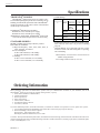
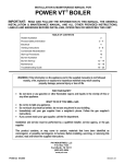
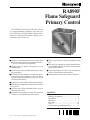
RA890F
Flame Safeguard
Primary Control
The RA890F Protectorelay™ Primary Control
is a nonprogramming, amplifying relay that provides solid state electronic flame safeguard protection for industrial and commercial gas, oil, or
combination gas-oil burners.
■ Employs rectification principle of electronic flame
detection using a flame rod, rectifying photocell, or
C7012A,C Ultraviolet Flame Detector.
■ Clipping pilot link jumper wire permits use with
standing pilots.
■ Can directly replace RA890E and mount on same
Q270A Subbase.
■ Solid state circuitry eliminates vacuum tube replacement and increases resistance to vibration. Power
application not required during Off cycle; no tube to
warm up before starting.
■ Push-to-reset safety switch in dust-resistant enclosure.
■ Built-in protection against ignition crossover in flame
rod systems.
■ Does not start if flame-simulating failure occurs in
flame detector circuit.
■ Automatic safety shutdown if flame fails on start, or
if flame not re-established after flame failure.
S.Y. • Rev. 11-94 • ©Honeywell Inc. 1994
■ Flame signal current is directly measurable at test
jack.
■ Line or 24 volt, automatic or manual controller can be
used. (Manual controller must open circuit on either
power or flame failure.)
■ Captive mounting screws allow easy mounting and
removal. Thermoplastic mounting base.
■ Optional alarm circuit indicates safety shutdown.
CONTENTS
Specifications ................................................. 2
Ordering Information ..................................... 2
Installation ..................................................... 4
Operation ....................................................... 7
Checkout ......................................................... 8
Service .......................................................... 10
Troubleshooting and Maintenance .............. 10
1
60-2034-7
60-2034—7
RA890F
SPECIFICATIONS • ORDERING INFORMATION
Specifications
TRADELINE® MODELS
Terminal Ratings:
®
TRADELINE models of this device are available. They
are selected and packaged to provide ease of stocking, ease of
handling, and maximum replacement value. TRADELINE®
model specifications are the same as those of the standard
model except as noted below.
TRADELINE® MODELS AVAILABLE:
RA890F for 120V, 50/60 Hz power supply.
RA890F for 240V, 50/60 Hz power supply.
ADDITIONAL FEATURES: TRADELINE® packed with
cross reference label and special cross reference listing.
Terminal
Electrical Load
3
Burner Full Load
Motor Locked
Rotor
(inrush)
Ignition a,b
Pilot Fuel Valve
4
5
STANDARD MODELS
Ignition a
Gas
Valveb
120 Vac 240 Vac
5.2A
2.6A
31.2A
15.6A
3.0A
1.5A
25 VA
25 VA
3.0A
1.5A
125 VA
125 VA
a
If ignition and motor are connected to terminal 3, terminal 4 cannot be used. This is to prevent overloading
relay 1K.
b
Alternate Rating: 25 VA pilot duty plus one or more
motorized valves with total rating 400 VA opening,
200 VA holding.
MODEL: RA890F Protectorelay™ Primary Control.
ELECTRICAL RATINGS:
Voltage and Frequency: 100V, 120V, 208V, 220V, or
240V, 50/60 Hz. As ordered.
Power Consumption:
60 Hz: 7.0W maximum, 1.7W standby.
50 Hz: 8.5W maximum, 3.0W standby.
VA Ratings:
60 Hz: 13.0 VA maximum, 8.3 VA standby.
50 Hz: 17.0 VA maximum, 13.6 VA standby.
Alarm Contacts: 3.0A at 24 Vac or 1.0A at 120 Vac in
suitable wiring enclosure.
Low Voltage Control Circuit (T-T): 0.3A.
Ordering Information
When purchasing replacement and modernization products from your TRADELINE® wholesaler or your distributor, refer to the
TRADELINE® catalog or price sheets for complete ordering number, or specify:
1. Order number (standard or TRADELINE®).
2. Voltage and frequency.
3. Flame response time.
4. Safety switch timing.
5. Alarm contacts, if desired.
6. Fast thermistor timing if desired.
7. Accessories, if desired.
If you have additional questions, need further information, or would like to comment on our products or services, please write or phone:
1. Your local Honeywell Home and Building Control sales office (check white pages of phone directory).
2. Home and Building Control Customer Logistics
Honeywell Inc., 1985 Douglas Drive North
Minneapolis, Minnesota 55422-4386 (612) 951-1000
In Canada—Honeywell Limited/Honeywell Limitée, 740 Ellesmere Road, Scarborough, Ontario M1P 2V9. International sales and service
offices in all principal cities of the world. Manufacturing in Australia, Canada, Finland, France, Germany, Japan, Mexico, Netherlands, Spain,
Taiwan, United Kingdom, U.S.A.
60-2034—7
2
RA890F
SPECIFICATIONS
NOTE: Allowable inrush can be up to ten times the pilot
duty rating.
RECYCLE TIME: Occurs immediately when flame loss
recognized. See Flame Failure Response Time.
THERMISTOR DELAY OF LOAD RELAY PULL-IN:
4 seconds nominal. Voltage level and ambient temperature affects delay time. Actual delay may be 2 to 30 seconds under ambient temperature extremes. Fast thermistor
model with 1 sec nominal delay time is available when
long delay is a problem. Fast delay model is available
only with the following specifications: 120V, 50/60 Hz,
15 sec safety switch, 0.8 flame response timing, for use
with flame rod detector only.
ALARM CONTACTS (Optional): Isolated spdt contacts.
Male quick-connect terminals (female quick-connects
included). See rating above.
DIMENSIONS: Approximately 5 x 5 x 5 in. (127 x 127 x
127 mm) including subbase.
MOUNTING: On Q270A Universal Mounting Base ordered separately.
APPROVALS: Underwriters Laboratories Inc Listed: 120V,
models only; File No. MP268, Guide No. MCCZ.
EXAMPLE: Pilot duty rating = 25 VA.
At 120V, running current is 25 = 0.21A.
Maximum allowable inrush is 10 times 0.21 = 2.1A.
Maximum Power Interruption: 12 milliseconds; longer
interruption causes 1K to drop out; burner shuts down.
After a short delay for component check, burner should
restart and operate normally.
FLAME FAILURE RESPONSE TIME: 0.8 seconds or
3 seconds nominal, as ordered. Three second response is
recommended for nonrecycling ignition cutoff service to
prevent nuisance shutdowns.
FLAME DETECTORS: Flame rod, rectifying photocell, or
C7012A,C Ultraviolet Flame Detector.
AMBIENT TEMPERATURE RATINGS:
Minimum:
Model
°F
°C
15 sec safety switch
-20
-29
30 sec safety switch
+10
-12
NOTE: All devices meeting UL components recognition
have the following symbol:
Replacement exchange controls that meet current UL
requirements are identified with the term REMFR’D
following the listing or component recognition mark.
Canadian Standards Association Certified: 120V models
only; File No. LR1620.
Factory Mutual Approved: Report No. 17678, 19417,
and 19784.
American Gas Association Design Certified for -20°F
(-29°C): Certificate No. 20-AL.
ACCESSORIES:
W136A Microammeter (includes 196146 Plug).
121708 Flame Simulator.
196146 Meter Connector Plug.
FSP1535 Tester for operational check of all RA890s.
Q270A1024 Mounting Subbase serves as junction box to
connect to external circuits. Q270A contains terminal
blocks with coded terminals and screws.
R482F Relay to provide safe-start checks when RA890F
is used in special standing pilot applications.
13891L Cover Assembly with reset button. 120 Vac model.
118702E Remote Reset Cover.
Maximum:
50 Hz
60 Hz
°F
°C
°F
°C
Without alarm contacts
115
46
125
52
With alarm contacts
105
41
115
46
Model
Models with 30 second safety switch operate safely at
temperatures to -30°F (-34°C) but may encounter difficulty
when resetting a tripped safety switch below the rated
temperature.
SAFETY SWITCH TIMING (LOCKOUT TIME): 15 or
30 seconds as ordered. Timings are proportional with
input voltages and temperatures. For RA890s that are
classified in Underwriters Laboratories Inc gas groups 6
and 6A and oil group 8, the maximum safety switch
timing with voltages ranging from 70 to 110 percent of
rated voltage and with ambients ranging from 32°F (0°C)
to 115°F (66°C) is allowed to be as high as 50 seconds.
FLAME ESTABLISHING PERIOD:
Models with 15 sec Safety Switch: Up to 15 sec.
Models with 30 sec Safety Switch: Up to 30 sec.
3
60-2034—7
RA890F
INSTALLATION
Installation
WHEN INSTALLING THIS PRODUCT…
1. Read these instructions carefully. Failure to follow them could damage the product or cause a hazardous
condition.
2. Check the ratings given in the instructions and on
the product to make sure the product is suitable for your
application.
3. Installer must be a trained, experienced, flame safeguard control technician.
4. After installation is complete, check out product operation as provided in these instructions.
Fig. 1—Mounting subbase in in. (mm).
VERTICAL
HORIZONTAL
45 DEGREES
MAXIMUM LEAN
2-7/8
(73.0)
CAUTION
1. Disconnect power supply before beginning installation to prevent electrical shock and equipment damage.
2. All external timers must be Listed or Component
Recognized by authorities that have jurisdiction
for the specific purpose for which they are used.
4-1/8 (104.8)
KNOCKOUTS (9) FOR
1/2 IN. (13) CONDUIT
WIRE SUBBASE
1. Disconnect power supply (see Fig. 2) before making
wiring connections to avoid electrical shock and equipment
damage. Assure all wiring complies with applicable electrical codes, ordinances, and regulations. Use NEC Class 1
(line voltage) wiring.
When wiring the Q270A Universal Mounting Base for
use with the RA890F, use the terminal designations 6, T and
T (printed in white).
2A. For normal installations, use moisture-resistant
No. 14 wire suitable for at least 167°F (75°C). For
high temperature installations, use moisture-resistant No. 14 wire selected for a temperature rating
above the maximum operating temperature for all
but the ignition and flame detector F leadwires.
a. For the ignition, use Honeywell Specification
no. R1061012 Ignition Cable or equivalent. (This
wire is rated at 350°F (175°C) for continuous
duty, and up to 500°F (260°C) for intermittent
use. It was tested to 25,000V.)
b. For the flame detector F leadwire, use Honeywell
Specification no. R1298020 or equivalent. (This
wire is rated up to 400°F (205°C) for continuous
duty. It was tested for operation up to 600V and
breakdown up to 7500V.)
2B. For ignition installations in a contaminating environment, use Honeywell Specification no. R1239001
High Tension Ignition Cable or equivalent. This
wire is very resistant to severe conditions of oil, heat,
and corona, and is tested to withstand high voltages
up to 25,000V rms in a salt bath for one minute
without breakdown. It is rated at 200°F (93°C) for
continuous duty, and up to 350°F (175°C) for intermittent use.
Refer to Fig. 3 and 4 for typical field wiring connections.
See Fig. 5 for schematic diagram. Follow the burner manufacturer’s instructions if supplied. Otherwise proceed as
follows.
LOCATION
Temperature
Install the RA890F where the surrounding temperatures
remain within the Ambient Operating Temperature Ratings
listed in the SPECIFICATIONS section.
Humidity
Install the RA890F where the relative humidity never
reaches the saturation point. Condensation of moisture on
the RA890F may cause enough leakage to short the flame
signal to ground and prevent the burner from starting.
Vibration
Do not install the RA890F where it could be subject to
excessive vibration. Vibration shortens the life of the electronic and mechanical components.
Weather
The RA890F is not designed to be weathertight. If it is
installed outdoors, use a suitable weathertight enclosure.
Mount Subbase
Locate the subbase where ambient temperature is within
the specified rating.
Mount the subbase so the top and bottom are horizontal
and the back is vertical. The subbase can lean backward as
much as 45 degrees when necessary. See Fig. 1.
60-2034—7
M8681
4
RA890F
INSTALLATION
IMPORTANT: Do not run high voltage ignition transformer
wires in the same conduit with the flame detector
wiring.
Fig. 3—Gas system with interrupted ignition.
POWER SUPPLY
L1
L2
(HOT)
5
IMPORTANT: When connecting wire to screw terminal of
terminal strip, wrap wire at least 3/4 of distance
around screw without overlapping. With appropriately sized screwdriver, tighten screw until wire is
snugly in contact with underside of screw and contact
plate. Tighten screw additional one-half turn. Do not
use a push-type ratchet screwdriver.
YES
NO
NO
NO
RA890F
NO
6
5
MAIN FUEL
7
VALVE(S)
T
4
IGNITION
T
3
F
1
G
2
LIMIT
CONTROLLER
1
2
3
PILOT VALVE
LOW VOLTAGE
CONTROLLER
M8717
HOOKUP
RA890E Replacement
When replacing an RA890E with an RA890F, no changes
are required in the wiring to the subbase. Leave the hot line
connected to terminal 1 even though it is not required to
operate the control.
TO FLAME
DETECTOR
(FLAME ROD OR
UV DETECTOR)
2
NC
USE TERMINALS
NC AND C FOR
NORMALLY CLOSED
ALARM INDICATOR
OR INTERLOCK
CIRCUIT IF DESIRED.
Fig. 2—Flame detector wiring.
6
NO
COM
4
5
LINE OR
LOW VOLTAGE
NO ALARM
LINE OR LOW
VOLTAGE ALARM
POWER SUPPLY
TYPICAL FLAME DETECTOR CONNECTIONS
PHOTOCELL
FLAME ROD
1
FOR INTERMITTENT IGNITION, CONNECT TO TERMINAL 3.
2
IF LINE VOLTAGE CONTROLLER IS USED, CONNECT IT BETWEEN
THE LIMIT CONTROLLER AND TERMINAL 6. JUMPER T-T.
3
HOOKUP FOR CONTINUOUS (STANDING) PILOT IS THE SAME AS
FOR INTERRUPTED IGNITION EXCEPT IGNITION AND PILOT
VALVE CONNECTIONS ARE NOT MADE.
4
SPDT ALARM TERMINALS OPTIONAL. IF LINE VOLTAGE IS USED,
RA890F MUST BE MOUNTED IN SUITABLE ENCLOSURE. ALARM
TERMINALS ARE ENERGIZED THROUGH RA890 SAFETY SWITCH.
ALARM WILL NOT SOUND UNTIL SAFETY SWITCH TRIPS OUT.
5
POWER SUPPLY. PROVIDE DISCONNECT MEANS AND OVERLOAD
PROTECTION AS REQUIRED.
6
FOR RA890E REPLACEMENT, LEAVE POWER CONNECTED TO
TERMINAL 1. SUBBASE WIRING CHANGES ARE NOT REQUIRED.
7
SOME AUTHORITIES HAVING JURISDICTION PROHIBIT THE WIRING
OF ANY LIMIT OR OPERATING CONTACTS IN SERIES WITH THE MAIN
FUEL VALVES (S).
X F
X F
X G
X G
C7012 ULTRAVIOLET DETECTOR
M8752
BLUE
YELLOW
BLACK
BLACK
X F
X G
POWER
SUPPLY
M8730
5
60-2034—7
RA890F
INSTALLATION
Fig. 4—Oil system with interrupted ignition.
POWER SUPPLY
L1
L2
(HOT)
1
2ND STAGE OIL
VALVE(S) (IF USED) 5
RA890F
6
5
T
4
T
3
LIMIT
CONTROLLER
IGNITION
3
2
BURNER
MOTOR
LOW VOLTAGE
CONTROLLER
F
4
1
TO FLAME
DETECTOR
(FLAME ROD OR
UV DETECTOR)
OIL VALVE(S) 5
2
1
POWER SUPPLY. PROVIDE DISCONNECT MEANS AND OVERLOAD
PROTECTION AS REQUIRED.
2
IF LINE VOLTAGE CONTROLLER IS USED, CONNECT IT BETWEEN
THE LIMIT CONTROLLER AND TERMINAL 6. JUMPER T-T.
3
FOR INTERMITTENT IGNITION, CONNECT TO TERMINAL 3.
4
FOR RA890E REPLACEMENT, LEAVE POWER CONNECTED TO
TERMINAL 1. SUBBASE WIRING CHANGES ARE NOT REQUIRED.
5
SOME AUTHORITIES HAVING JURISDICTION PROHIBIT THE WIRING
OF ANY LIMIT OR OPERATING CONTACTS IN SERIES WITH THE
MAIN FUEL VALVES (S).
2
G
M8753
Fig. 5—Schematic of the RA890F.
LINE VOLTAGE
CONTROLLER
LIMIT
CONTROLLER
3
RA890F
6
SAFETY SWITCH
HEATER
2K3
2
1K1
2K2
5
1K4
5
MAIN GAS VALVE(S)
OR SECOND STAGE
OIL VALVE(S)
7
(IF USED)
2K1
LOW VOLTAGE
CONTROLLER
3
INTERRUPTED
IGNITION
4
THERMISTOR
4
T
1K3
3
T
1K
2K
TEST
JACK
1K2
SAFETY
SWITCH
2
F
NOT
USED
1
ELECTRONIC
NETWORK
TO FLAME
DETECTOR
2
G
MASTER
SWITCH
WIRE JUMPER
(PILOT LINK)
1
PROVIDE DISCONNECT MEANS AND OVERLOAD PROTECTION AS REQUIRED.
2
RA890F IS POWERED AT TERMINAL 6 ONLY. WHEN REPLACING ANOTHER MODEL, LEAVE HOT LINE (L1) CONNECTED
TO TERMINAL 1, EVEN THROUGH IT IS NOT NECESSARY FOR OPERATION.
3
MAY USE LINE OR LOW VOLTAGE CONTROLLER. IF LINE VOLTAGE CONTROLLER IS USED, CONNECT IT BETWEEN THE LIMIT
CONTROLLER AND TERMINAL 6. JUMPER T-T.
4
FOR INTERMITTENT IGNITION, CONNECT TO TERMINAL 3.
5
OPENING OF A LIMIT CONTROL OR LINE VOLTAGE CONTROLLER INTERRUPTS ALL POWER TO THE CONTROL,
INCLUDING THE ELECTRONIC NETWORK.
6
ALL WIRING MUST BE NEC CLASS 1.
7
SOME AUTHORITIES HAVING JURISDICTION PROHIBIT THE WIRING OF ANY LIMIT OR OPERATING CONTACTS IN SERIES WITH
THE MAIN FUEL VALVES (S).
60-2034—7
6
PILOT GAS VALVE (S),
OR BURNER MOTOR
AND DELAYED OIL
VALVE; INTERMITENT
IGNITION
7
6
1
L2
L1
(HOT)
POWER
SUPPLY
M8754
RA890F
INSTALLATION • OPERATION
MOUNT RA890F
Disconnect power supply.
Remove relay cover (see Fig. 6) and position the RA890F
over the Q270A Subbase. Start all ten mounting screws and
tighten uniformly. These screws complete electrical circuits
(terminal 1 excepted) and hold the RA890F to the subbase.
As shipped from the factory, the RA890F is suitable for
use with interrupted or intermittent systems.
FOR STANDING PILOT SYSTEMS ONLY
For use with standing pilot systems. Clip the pilot link
(wire loop in Fig. 7) as follows:
1. Turn off power.
2. Clip pilot link with side cutters. Do not twist off
because damage to circuit board can result. Remove any
pieces of the wire.
3. Be sure there is electrical clearance between the two
ends of the link, and from link ends to the test jack or relay
frame. Then restore power.
Fig. 6—RA890F and Q270A Subbase.
Q270A
SUBBASE
TERMINAL
BLOCKS
CAPTIVE
MOUNTING
SCREWS (10)
Fig. 7—Location of arc gap protector on
RA890F.
LOAD RELAY (1K)
FLAME RELAY (2K)
COVER
SAFETY SWITCH
RESET
PUSHBUTTON
TEST
JACK
PILOT LINK
ARC GAP
PROTECTOR
FLAME
CURRENT
TEST JACK
ARC GAP
PROTECTOR
OPTIONAL
ALARM
CONTACT (3)
THUMBSCREW
PILOT LINK JUMPER WIRE
(0N BASE ALONGSIDE TEST JACK)
M8767
M8766
Operation
NORMAL OPERATION SUMMARY
Normal control operation is summarized below. Refer to
Fig. 5 for the internal schematic of the control.
1. Call for heat—Load relay pulls in after a slight delay
(flame relay must be out), ignition starts, pilot valve or burner
motor is powered. Safety switch heats.
2. Flame proved—Flame relay pulls in, safety switch
heater is de-energized, main valve is powered, ignition is cut
off (when used for interrupted ignition).
3. Call for heat satisfied—Load relay drops out, fuel
valves close, burner motor stops, and flame relay drops out.
NOTE: The pull-in of the load relay is delayed by a thermistor with a nominal delay time of 3 to 5 seconds. The
thermistor is affected by ambient temperature, and the
delay time may be as short as 2 seconds when the
temperature is high and as long as 30 seconds when the
temperature is low. As the thermistor warms up, the 1K
relay might hum slightly before it pulls in. This is normal.
7
60-2034—7
RA890F
CHECKOUT
Checkout
IF A STEADY READING OF AT LEAST MINIMUM
STRENGTH CANNOT BE OBTAINED, ONE OR MORE
OF THE FOLLOWING CONDITIONS CAN EXIST:
• Improper supply voltage.
• Defective flame detector wiring including:
— Open circuits.
—Short circuits.
— High resistance shorts caused by moisture, accumulated dirt, or improper choice of detector leadwire
for the particular installation.
• Improper sighting, improper viewing window, or dirty
viewing window for optical detectors.
• Improper application of a flame rod including:
— Insufficient ground area.
— Poor location of flame rod in flame.
— Excessive heat on flame rod insulator (greater than
600°F (316°C).
— Ignition interference.
• Improper application of a vacuum photocell, including:
— Temperature over 165°F (74°C) at photocell.
— Dirty photocell envelope.
• Defective sensor.
CAUTION
Use extreme care while testing the RA890F; line
voltage can be present on most terminals when
power is on.
PRELIMINARY CHECKS
Before placing the system in operation, complete the
following preliminary checks:
1. Check through wiring. Use a meter to check the continuity of all circuits. See Fig. 8.
2. Check flame detector installation.
3. Check burner adjustments.
4. Thoroughly purge gas piping.
5. Reset the safety switch by pushing in and then releasing the green safety switch button.
6. If the system has a standing pilot, make sure the pilot
link (Fig. 7) is removed and the pilot is lit.
CHECKOUT REQUIRED
Before the installation is complete, satisfactorily perform
all checkout tests indicated below.
Flame Current Check (all installations).
Pilot Turndown Test (all installations that require proof of
pilot before main fuel valve is opened).
Safe Shutdown Checks—Flame failure, power failure,
limit action (all installations).
Hot Refractory Hold-In (photocell applications only).
Fig. 8—Connecting meter to read flame
current.
196146 METER
CONNECTOR
PLUG (SUPPLIED
WITH W136)
W136
FLAME CURRENT CHECK
The flame current check is the best indicator of proper
flame detector application. Perform the check at the time of
installation, at any time service is done on the system, and at
least once a month or more often while the system is in
operation. This prevents shutdowns due to poor flame signal.
Perform test by connecting a W136 (or equivalent)
microammeter in series with the flame detector and reading
the flame signal while the burner is operating.
Insert a 196146 Meter Connector Plug, wired color-tocolor to the W136A leadwires, into the test jack on the
RA890F. This automatically puts the microammeter in series with the flame detector.
If a meter connector plug is not available, disconnect the
flame detector lead from the F terminal; then connect this
lead to the Black lead of the microammeter, and connect the
Red lead of the microammeter to the F terminal.
When reading the flame current, assure the following
criteria are met:
1. The flame current is steady; meter does not vary more
than a needle width.
2. The flame current is at least two microamperes for a
rectification type detector like used with the RA890F. The
normal operating range is 2 to 5 microamperes.
60-2034—7
RA890
CK
BLA
BLA
FLAME
CURRENT
TEST JACK
D
RE
CK
RED
IF 196146 METER CONNECTOR PLUG IS NOT AVALIABLE —
W136
F LEAD
FLAME
DETECTOR
G LEAD
BLACK
+
RED
F
G
RA890
M8755
8
RA890F
CHECKOUT
PILOT TURNDOWN TEST
10. Repeat the entire turndown test until the flame is
established promptly in step 7.
11. Turn up the pilot to full flame at the completion of the
test. Perform a flame current check before leaving the job.
CAUTION
The pilot turndown test should be performed only
by qualified personnel and the instructions should
be followed carefully.
SAFE SHUTDOWN CHECKS
Limit Action
With the burner operating, lower the high limit setting to
simulate an overheated boiler or furnace. Normal shutdown
should occur. Restore the normal limit setting and the burner
should restart.
Use manual reset limits with the RA890F to prevent the
system from cycling off the high limit and to assure that the
condition that causes the limit action is detected as soon as
possible.
On systems that prove a pilot before the main fuel valve
can be opened, perform a pilot turndown test to prove that the
main burner can be lighted by the smallest pilot that will hold
in the flame relay. Perform a flame current check before and
after the pilot turndown test.
1. Open the main power switch.
2. Shut off the fuel supply to the main burner only by
closing the manual main burner shutoff cock. Do not shut off
the fuel supply to the pilot valve.
3. Restore power to the relay.
4. Start the system by raising the setpoint of the controller (or pressing the Start button). The pilot will light and pull
in the flame relay.
5. Reduce the size of the pilot flame to the turndown
condition by slowly closing the manual valve on the pilot gas
line. At the turndown condition, the pilot will be small
enough to just hold in the flame relay (2K).
a. Turn down the pilot until relay 2K drops out.
b. Slowly turn up the pilot again just until relay 2K pulls
back in.
c. Again turn down the pilot slightly, but not enough so
the relay drops out.
If the relay drops out again, simply turn up the pilot and
try again. The closer the pilot is to the dropout condition, the
more conclusive the test will be.
6. Check that the pilot is lit and relay 2K is pulled in.
7. Open the manual main burner shutoff cock. Main
flame should light smoothly within one second. If the burner
does not light within one second, close the shutoff cock and
shut off power to the relay. Proceed to step 9.
8. If the burner lights, repeat step 7 two or three times to
verify smooth lightoff.
9. If the lightoff is unsatisfactory, readjust the flame
detector to require a larger pilot flame to hold in the flame
relay. This usually requires:
a. Resighting an ultraviolet or photocell type detector
farther out on the axis of a pilot flame, or
b. Adjusting a flame rod detector so that a larger minimum pilot is required.
Flame Failure
With the burner operating, close the manual fuel valves to
simulate a flame failure. System should lock out in safety
switch timing (15 or 30 seconds). After the safety switch
cools, open the manual valves and reset the safety switch.
The burner should restart.
Power Failure
With the burner operating, open and then immediately
close the line switch to simulate a power failure. Burner
should shut down. After a short delay for component check,
burner should restart and operate normally.
HOT REFRACTORY HOLD-IN (PHOTOCELL OIL
INSTALLATION ONLY)
If hot refractory holds in the flame relay at the end of the
burner-on cycle, the system cannot restart until the relay
drops out. Check for hot refractory hold-in by observing the
flame relay for immediate dropout at the end of a long
burner-on period. If the relay does not drop out, resight the
photocell so it does not sight the refractory, or decrease
photocell sensitivity using aperture disks or filters.
NOTE: At the completion of all checkout tests, make sure
that the RA890 is not on safety lockout, that the pilot is
turned up to its normal level, and that all limit settings are
correct. Operate the system through one normal cycle
before leaving the installation.
CAUTION
If the pilot needs to be adjusted and rechecked,
allow five minutes for the purge of unburned gases
in the firebox before proceeding to the next step.
9
60-2034—7
RA890F
SERVICE • TROUBLESHOOTING
Service
nuisance shutdown, etc. The following should be included in
any program:
1. Replace the vacuum tubes in the C7012 Flame Detector (when used) annually.
2. Perform a flame failure check and pilot turndown test
whenever the burner is serviced, and at least annually.
3. Inspect and clean the detector and any viewing windows as often as required by soot accumulation and heat
conditions at the detector.
4. Perform a flame current check at least monthly and
more often when a shutdown may be costly.
5. Clean contacts only when required by failure to operate properly.
GENERAL SERVICE
1. Only qualified personnel should attempt to service
heating equipment or controls.
2. Perform all checks required in the Checkout section
when replacing the RA890, or when relighting or restoring
power to the system after shutdown.
3. The captive mounting screws carry current; always
disconnect power before loosening or tightening the mounting screws.
4. On each service call, check the controller for the approximately correct calibration and differential; assure that it
is mounted securely. (See controller instructions.)
5. Never use oil on any part of the RA890F.
6. When cleaning the burner, clean the flame detector.
7. Do not manually push in the RA890 relays. This may
damage the relays and it is an unsafe practice because it
overrides the protective features of the relay. Clean relay
contacts only as instructed below.
CONTACT CLEANING
Clean the relay contacts on the RA890 only when required and then only with Honeywell part no. 132569 Contact Cleaner. The contact cleaner comes in pressurized spray
cans; directions for its use are printed on the can. Do not use
other commercial contact cleaners. Most cleaners tested
were found to leave deposits on the contact surfaces or to
attack RA890 chassis parts.
PERIODIC MAINTENANCE
The specific maintenance schedule setup depends on
several factors including type of equipment being controlled,
operating conditions (dirt and heat especially), cost of a
Troubleshooting
When trouble occurs in the heating system and its cause is
not immediately apparent, the service technician can apply
the following step-by-step checkout to locate the cause of
most problems. Refer to Fig. 3 and 4 for terminal locations,
and to Fig. 6 for location of component parts.
5. Check position of flame relay. (When a line voltage
controller is used, observe the action of the flame relay on a
call for heat.)
a. If the flame relay is out, proceed to step 6.
b. If the flame relay is pulled in, check for a flame simulating condition.
(1) Insert flame simulator plug or part no. 196146
Cable Plug into the test jack; do not ground the
other end.
(2) If flame relay holds in, replace the RA890.
(3) If flame relay drops out, trouble is in the flame
detector or external circuit. Check for light reaching the photocell, hot refractory hold-in, or defective wiring.
CAUTION
Use extreme care troubleshooting the RA890F;
line voltage can be present on most terminals when
power is on.
TEST STANDBY OPERATION
1. Set controller not to call for heat.
2. Reset the safety switch by pushing in and then releasing the green safety switch reset button.
3. Close the line switch.
4. Check for line voltage at terminals 2 and 6. (Voltage
will be zero when a line voltage controller is used; check for
line voltage when controller is set to call for heat.)
a. Voltage must be within +10 to -15 percent of the rated
voltage.
b. When voltage is zero (with low voltage controller), be
sure limit switch contacts are closed and check power
supply. Check for blown fuses, open circuit, or open
disconnect switch.
60-2034—7
TEST STARTING OPERATION
6. Set controller to call for heat . (If control uses a line
voltage controller, go back to steps 4 and 5.)
7. Observe load relay for pull-in.
a. Load relay pulls in to light pilot and start burner—
proceed to step 11.
b. Load relay does not pull in—proceed to step 8.
c. Load relay pulls in but does not light or burner does
not start—proceed to step 10.
8. Check line voltage controller, if used, and the limit; if
the load relay does not pull in, check again for power at
10
RA890F
TROUBLESHOOTING
Difficulty Resetting Safety Switch
(30 Second Safety Switch Models)_
Ambient temperature may be below +10°F (-12°C). Problem is corrected by warming the safety switch.
terminal 6 with the controller calling for heat. If there is
power at terminal 6 and a line voltage controller is used,
clean all relay contacts. Replace the RA890 if the relay still
does not pull in. If a low voltage controller is used, proceed
to step 9.
9. Check low voltage controller, if used, by jumping T-T.
a. Load relay pulls in with T-T jumpered; check controller and external circuit.
b. Load relay does not pull in with T-T jumpered; clean
all relay contacts. Replace the RA890 if the load relay
still does not pull in.
10. If the load relay pulls in but the pilot will not light or the
burner will not start, check voltage at terminals 3-2 or 4-2.
a. If no voltage at terminals 3-2 or 4-2 clean relay contacts. Replace the RA890 when trouble cannot be
corrected.
b. If normal line voltage at terminals 3-2 or 4-2, check
external burner, ignition, and valve circuits. Check
wiring, burner adjustment, ignition system including
electrode spacing and location, oil quality, character
and efficiency of oil atomization, fuel supply pressure,
flame pattern, flame character and quality, pilot location with respect to main burner, flame detector, or
other conditions that may delay lightoff.
Repeated Lockouts Or Control Failures
The most common causes of repeated failures of the control or flame detector or repeated lockouts are:
a. High ambient temperatures—over 125°F (52°C). Subtract 10°F (6°C) for alarm contacts and 10°F (6°C) for
50 Hz operation.
b. Supply voltage variation greater than +10 to -15 percent.
c. Electrical overloading of the contacts.
d. Marginal microampere signal.
e. Frequent cycling with high ambient temperatures.
IGNITION INTERFERENCE
(Flame Rod Detectors Only)
Ignition interference is a false signal from a spark ignition
system superimposed on the flame signal. The interference
may be additive or subtractive (increases or decreases the
flame current), and in some instances may be sufficient to
destroy the electronic network of the RA890E. The RA890F
network is protected against interference by the arc gap
shown in Fig. 7.
The arc gap conducts at high voltage levels. It also glows
when it conducts, providing a visual indication that interference is occurring. This prevents the control from operating
and causes a shutdown.
Ignition interference (below the arcing level) can be
determined by measuring the flame current with ignition and
pilot on, and then with only pilot on. Any significant difference may indicate interference.
TESTING FLAME DETECTING FUNCTION
11. Observe the flame relay (right relay) for pull-in when
flame is established.
a. Flame relay pulls in; proceed to step 13.
b. Flame relay does not pull in; proceed to step 12.
12. Check the flame relay with a 121708 Flame Simulator
if available (follow the instructions with the simulator), or
check the following:
a. Perform a flame current check according to the flame
current check section.
b. If the current is satisfactory, replace the RA890.
c. If the current is not satisfactory, check all items listed
in the Flame Current Check section.
IMPORTANT: When an RA890F replaces an RA890E,
there may be installations where ignition interference
is not sufficient to destroy the RA890E, but is sufficient
to prevent operation of the RA890F due to its arc gap
protection. Be very suspicious of ignition interference
on any installation where the RA890E operates and
the RA890F does not.
OBSERVE SEQUENCING OPERATION
13. Observe the second stage oil valve or main gas valve
for opening when flame relay pulls in.
a. If valve does not open, check for line voltage at terminals 2-5.
(1) Normal voltage—check valve and valve circuit.
(2) Zero voltage—clean relay contacts. Replace the
RA890 if this does not correct the problem.
14. Observe ignition for cutoff when flame relay pulls in
when connected to terminal 4.
a. If ignition stays on and wiring checks out, replace the
RA890.
HOW TO ELIMINATE INTERFERENCE
(Tabulated in Order of Importance)
1. Provide adequate flame grounding area.
2. Be sure the ignition electrode and the flame rod are on
opposite sides of the grounding area.
3. Check for correct spacing on the ignition electrode.
Spacing should be 1/16 in. to 3/32 in. (1.6 to 2.4 mm) for
6,000V systems and 1/8 in. (3.2 mm) for 10,000V systems.
4. Eliminate any marginal spacing at other areas along
the lead routes. Replace any deteriorated leads.
MISCELLANEOUS PROBLEMS
Relay Chatter
Load relay chatter can result from extreme low voltage
(notify power company) or from a loose connection (tighten).
Flame relay chatter may result from improper combustion (adjust burner) or soot or carbon on flame detector
(clean, and correct the cause).
11
60-2034—7
Home and Building Control
Honeywell Inc.
1985 Douglas Drive North
Golden Valley, MN 55422
60-2034—7
Printed in U.S.A.
Home and Building Control
Honeywell Limited—Honeywell Limitée
740 Ellesmere Road
Scarborough, Ontario
M1P 2V9
12
Helping You Control Your World
QUALITY IS KEY