1
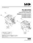
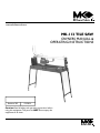
www.mkdiamond.com
MK-112 TILE SAW
OWNERS MANUAL &
OPERATING INSTRUCTIONS
Revision 202
02.2004
Caution: Read all safety and operating instructions before
using this equipment. This parts list MUST accompany the
equipment at all times.
SAFETY INSTRUCTIONS FOR THE MK-112 TILE SAW
Congratulations on your purchase of a MK-112 Tile Saw. We are certain that you will be pleased with your
purchase. MK Diamond takes pride in producing the finest construction power tools and diamond blades in the
industry.
Operated correctly, your MK-112 should provide you with years of service. In order to help you, we have
included this manual. This owners manual contains information necessary to operate and maintain your MK-112
safely and correctly. Please take a few minutes to familiarize yourself with the MK-112 by reading and reviewing
this manual.
If you should have questions concerning your MK-112, please feel free to call our friendly customer service
department at: 800 421-5830
Regards,
MK Diamond
2
TABLE OF CONTENTS
SAFETY
DAMAGE PREVENTION AND INFORMATION MESSAGES___________ 4
SAFETY MESSAGES_________________________________________ 4
GENERAL SAFETY PRECAUTIONS AND HAZARD SYMBOLS________ 4
CALIFORNIA PROPOSITION 65 MESSAGE_______________________ 6
ELECTRICAL REQUIREMENTS AND GROUNDING INSTRUCTIONS___ 8
TILE SAW SPECIFIC WARNINGS______________________________ 10
SAFETY LABEL LOCATIONS__________________________________ 10
PRODUCT SPECIFICATIONS_________________________________ 11
UNPACKING, TRANSPORT and ASSEMBLY
UNPACKING_______________________________________________
CONTENTS________________________________________________
TRANSPORT_ _ _____________________________________________
ASSEMBLY________________________________________________
12
12
12
13
SETUP, ADJUSTMENT & OPERATION
SETUP_ _ __________________________________________________ 14
ADJUSTMENT & OPERATION_________________________________ 16
CLEANUP_________________________________________________ 18
MAINTENANCE AND TROUBLESHOOTING
MAINTENANCE_ _ ___________________________________________ 19
TROUBLESHOOTING________________________________________ 21
EXPLODED VIEW AND PARTS LIST
EXPLODED VIEW___________________________________________ 22
PARTS LIST_______________________________________________ 23
THEORY
THEORY OF DIAMOND BLADES_ _ _____________________________ 26
ACCESSORIES_____________________________________________ 26
ORDERING & RETURN INSTRUCTIONS
ORDERING INFORMATION___________________________________
RETURN MATERIALS POLICY________________________________
PACKAGING INSTRUCTIONS_________________________________
AUTHORIZED SERVICE CENTERS__ ___________________________
3
27
27
27
27
SAFETY
Read and follow all safety, operating and maintenance instructions. Failure to read and follow these instructions
could result in injury or death to you or others. Failure to read and follow these instructions could also result in
damage and/or reduced equipment life.
SAFETY MESSAGES:
A safety message alerts you to potential hazards that could hurt you or others. Each safety message is preceded
by a safety alert symbol (
) and one of three words: DANGER, WARNING, or CAUTION.
DANGER
You WILL be KILLED or SERIOUSLY INJURED if you do not follow directions.
WARNING
You CAN be KILLED or SERIOUSLY INJURED if you do not follow directions.
CAUTION
You CAN be INJURED if you do not follow directions. It may also be used to alert against unsafe practices.
DAMAGE PREVENTION AND INFORMATION MESSAGES:
A Damage Prevention Message is to inform the user of important information and/or instructions that could lead
to equipment or other property damage if not followed. Information Messages convey information that pertains
to the equipment being used. Each message will be preceded by the word NOTE, as in the example below.
NOTE:
Equipment and/or property damage may result if these instructions are not followed.
GENERAL SAFETY PRECAUTIONS AND HAZARD SYMBOLS:
In order to prevent injury, the following safety precautions and symbols should be followed at all times!
Safety Precautions:
ALWAYS read this Owner’s Manual before operating the machine.
ALWAYS keep the Blade Guards in place.
REMOVE ADJUSTING KEYS AND WRENCHES
Form a habit of checking to see that keys and adjusting wrenches are removed from the power tool
before it is turned on.
KEEP WORK AREA CLEAN
Cluttered work areas and benches invite accidents.
DO NOT USE IN DANGEROUS PLACES
DO NOT use power tools in damp or wet locations nor expose them to rain. Always keep the work area
well lighted.
KEEP CHILDREN AWAY
All visitors and children should be kept a safe distance from work area.
4
SAFETY
MAKE THE WORKSHOP KID PROOF
Make the workshops kid proof by using padlocks, master switches or by removing starter keys.
DO NOT FORCE THE TOOL
A power tool will do a job better and safer operating at the rate for which it was designed.
USE THE RIGHT TOOL
DO NOT force a tool or an attachment, to do a job that it was not designed to do.
USE THE PROPER EXTENTION CORD
If using an extension cord make sure it is in good condition first. When using an extension cord, be
sure to use one heavy enough to carry the current your product will draw. An undersized cord will cause
a drop in line voltage that will result in a loss of power and overheating. TABLE 1, Page 9 shows the
correct AWG size to use depending on cord length and nameplate ampere rating. If in doubt, use the
next heavier gage. The smaller the gage number, the heavier the cord.
USE PROPER APPAREL
DO NOT wear loose clothing, gloves, neckties, rings, bracelets, or other jewelry that may be caught in
moving parts. Non-slip footwear is recommended. Wear protective hair covering to contain long hair.
ALWAYS wear approved eye protection.
ALWAYS wear approved respiratory protection.
SECURE WORK
Clamps or a vise should be used to hold work whenever practical. Keeping your hands free to operate
a power tool is safer.
DO NOT OVERREACH
Keep proper footing and balance at all times by not overreaching.
MAINTAIN TOOLS WITH CARE
Keep tools clean for the best and safest performance. Always follow maintenance instructions for
lubricating, and when changing accessories.
DISCONNECT TOOLS
Power tools should always be disconnected before servicing or when changing accessories, such as
blades, bits, cutters, and the like.
ON / OFF
ALWAYS place the power ON/OFF switch in the OFF position when the saw is not in use.
5
SAFETY
USE RECOMMENDED ACCESSORIES
Consult the owner’s manual for recommended accessories. Using improper accessories may increase
the risk of personal or by-stander injury.
NEVER STAND ON THE TOOL
Serious injury could occur if a power tool is tipped, or if a cutting tool is unintentionally contacted.
CHECK FOR DAMAGED PARTS
Before using a power tool, check for damaged parts. A guard or any other part that is damaged should
be carefully checked to determine it would operate properly and perform its intended function. Always
check moving parts for proper alignment or binding. Check for broken parts and mountings and all other
conditions that may affect the operation of the power tool. A guard, or any damaged part, should be
properly repaired or replaced.
DIRECTION OF FEED
ALWAYS feed work into a blade or cutter against the direction of rotation. A blade or cutter should
always be installed such that rotation is in the direction of the arrow imprinted on the side of the blade
or cutter.
NEVER LEAVE A TOOL UNATTENDED
TURN POWER OFF - Do not leave a tool until it comes to a complete stop. Always turn a power tool
OFF when leaving the work area, or, when a cut is finished.
CALIFORNIA PROPOSITION 65 MESSAGE:
WARNING
Some dust created by power sanding, sawing, grinding, drilling, and other construction activities contain
chemicals known [to the State of California] to cause cancer, birth defects or other reproductive harm. Some
examples of these chemicals are:
• Lead, from lead-based paints
• Crystalline silica, from bricks and cement and other masonry products and
• Arsenic and chromium, from chemically treated lumber
For further information, consult the following sources:
http://www.osha.gov/SLTC/silicacrystalline/index.html
http://www.oehha.org/prop65/out_of_date/6022kLstA.html
Your risk from these exposures varies depending on how often you do this type of work. To reduce your
exposure to these chemicals, work in a well-ventilated area, and work with approved safety equipment, such as
those dust masks that are specially designed to filter out microscopic particles.
6
SAFETY
Hazard Symbols:
ELECTRICAL SHOCK
NEVER touch electrical wires or components while the engine is running. They can be sources of
electrical shock which could cause severe injury or burns.
on
ROTATING PARTS
Keep hands, feet, hair, and clothing away from all moving parts to prevent injury. Never operate the
engine with covers, shrouds, or guards removed.
OVER SPEED
((
))
NEVER tamper with the governor components or settings to increase the maximum speed. Severe
personal injury and damage to the engine or equipment can result if operated at speeds above
maximum.
DO NOT EXPOSE TO RAIN
DO NOT expose to rain or use in damp locations.
WARNING
Sawing and drilling generates dust. Excessive airborne particles may cause irritation to eyes, skin and
respiratory tract. To avoid breathing impairment, always employ dust controls and protection suitable to the
material being sawed or drilled; See OSHA (29 CFR Part 1910.1200). Diamond Blades improperly used are
dangerous. Comply with American National Standards Institute Safety Code, B7.1 and, Occupational Safety and
Health Act covering Speed, Safety Guards, Flanges, Mounting Procedures, General Operating Rules, Handling,
Storage and General Machine Conditions
7
SAFETY
ELECTRICAL REQUIREMENTS AND GROUNDING INSTRUCTIONS:
In order to prevent potential electrical shock and injury, the following electrical safety precautions and symbols
should be followed at all times!
WARNING
In case of a malfunction or breakdown, grounding provides a path of least resistance for electric current
to reduce the risk of electric shock. This tool is equipped with an electric cord having an equipmentgrounding conductor and a grounding plug. The plug must be plugged into a matching outlet that is
properly installed and grounded in accordance with all local codes and ordinances.
• Do not modify the plug provided – if it will not fit the outlet; have the proper outlet installed by a
qualified electrician
• Improper connections of the equipment-grounding conductor can result in a risk of electric shock. The equipment-grounding conductor is the insulated conductor that has an outer surface that
is green, with or without yellow stripes. If repair or replacement of the electric cord or plug is
necessary, do not connect the equipment-grounding conductor to a live terminal
• Check with a qualified electrician or service personnel if the grounding instructions are not
completely understood, or if in doubt as to whether the tool is properly grounded
• Use only 3-wire extension cords that have 3-prong grounding plugs and 3-pole receptacles that
accept the tool’s plug
• Repair or replace a damaged or worn cord immediately
WARNING
This tool is intended for use on a circuit that has an outlet that looks like the one shown in Sketch A of
Figure 1. The tool has a grounding plug that looks like the plug illustrated in Sketch A of FIGURE 1. A
temporary adapter, which looks like the adapter illustrated in sketches B and C, may be used to connect
this plug to a 2-pole receptacle as shown in Sketch B, if a
properly grounded outlet is not available. The temporary adapter
should be used only until a properly grounded outlet can be
installed by a qualified electrician. The green-colored rigid ear,
lug, and the like, extending from the adapter, must be connected
to a permanent ground such as a properly grounded outlet box.
NOTE:
Use of a temporary adapter is not permitted in Canada
FIGURE 1
WARNING
To reduce the risk of electrocution, keep all connections dry and off the ground.
A Ground Fault Circuit Interrupter (GFCI) should be provided on the circuit(s) or outlet(s) to be used for
the Saw. Receptacles are available having built-in GFCI protections and may be used for this measure
of safety.
When using an extension cord, the GFCI should be installed closest to the power source, followed by the
extension cord and lastly, the saw.
8
SAFETY
To avoid the possibility of the appliance plug or receptacle getting wet, position the saw to one side of a
wall mounted receptacle. This will prevent water from dripping onto the receptacle or plug. A “drip loop,”
shown in FIGURE 2, should be arranged by the user to properly position the power cord relative to the
power source.
The “drip loop” is that part of the cord below the level of the receptacle, or the
connector, if an extension cord is used. This method of positioning the cord prevents
the travel of water along the power cord and coming in contact with the receptacle.
If the plug or receptacle gets wet, DO NOT unplug the cord. Disconnect the fuse or
circuit breaker that supplies power to the tool. Then unplug and examine for presence
of water in the receptacle.
Drip Loop
FIGURE 2
WARNING
Use only extensions cords that are intended for outdoor use. These extension cords are identified
by a marking “Acceptable for use with outdoor appliances; store indoors while not in use.” Use
only extension cords having an electrical rating not less than the rating of the product. Do not use
damaged extension cords. Examine extension cords before using and replace if damaged. Do not
abuse extension cords and do not yank on any cord to disconnect. Keep cords away from heat and
sharp edges. Always disconnect the extension cord from the receptacle before disconnection the
product form the extension cord.
WARNING
To reduce the risk of electrocution, keep all connections dry and off the ground. Do not touch the
plug with wet hands.
WARNING
Use of under size extension cords result in low voltage to the motor that can result in motor burnout
and premature failure. MK Diamond warns that equipment returned to us showing signs of being run
in a low voltage condition, through the use of undersized extension cords will be repaired or replaced
totally at the customers expense. There will be no warranty claim.
To choose the proper extension cord,
• Locate the length of extension cord needed in TABLE 1 below.
• Once the proper length is found, move down the column to obtain the correct AWG size required
for that length of extension cord.
Extension Cord Minimum Gage for Length
Volts
120 V
Total Length of Cord in Feet
25 ft.
50 ft.
100 ft.
150 ft.
AWG
AWG
AWG
AWG
14
12
TABLE 1
9
Not Recommended
SAFETY
SAFETY LABEL LOCATIONS
Safety labels are located according to Figures 1 through 3 below. The labels contain important safety
information. Please read the information contained on each safety label. These labels are considered a
permanent part of your saw. If a label comes off or becomes hard to read, contact MK Diamond or your dealer
for a replacement
Item
1A
1B
2
3
4
Location
Rail – Top/Left Upper
Rail – Top/Left Lower
Water Pan – Back/Left
Water Pan – Back/Right
Water Pan – Front
Description
Caution – Use with Ground Fault Circuit Interrupter
Warning – Read Owners Manual
MK-112 Serial Number
MK Service Information
MK-112 Title
B
A
1
2
3
4
TILE SAW SPECIFIC WARNINGS:
WARNING Wear eye protection.
Use splash hood for every operation for which it can be used.
Disconnect saw before servicing, when changing cutting blades, and cleaning.
Replace damaged cutting blade before operating.
10
Part No.
155678
155806
160469
155038
160468
SAFETY
PRODUCT SPECIFICATIONS
The MK-112 is a versatile Tile Saw. Operated and used according to this manual, the MK-112 will provide years
of dependable service.
General Description
The saw includes a powerful 115V electric motor. It is capable of cutting tile up to thirty-six (36) inches in length
and twenty four (24) inches diagonally. For cuts at 45°, the saw can cut to a depth of 1-3/4" and for cuts at 90°
it can cut up to a depth of 2-1/2".
Motor Specifications
Motor specifications for the MK-112 are listed in Table 2 below.
Voltage
Power Consumption
Frequency
RPM
Horse Power
115V
650W
60Hz
3400 rpm
1 hp
TABLE 2
Blade Capacity:
The MK-112 uses a eight (8) inch (203mm) diameter, wet cutting continuous rim, MK Diamond blade with a
seven-eighths (7/8) inch (22.225 mm) arbor.
Tile Types:
The MK-112 can cut a variety of tile types including stone, masonry, and lapidary products.
NOTE:
The MK-112 is not designed to cut plastic, wood or metals.
11
UNPACKING, TRANSPORT and ASSEMBLY
UNPACKING
CAUTION Use proper lifting techniques when lifting the MK-112
If not done yet, remove the MK-112 Saw and accessory box from the carton.
CONTENTS
In your container, you will find
A. One (1) MK-112 Saw
B. One (1) 8-inch wet cutting continuous rim blade,
C. One (1) Water Pump
D. One (1) 5mm wrench
E. One (1) 19mm wrench
F. One (1) 5mm Allen key
G. One (1) Protractor/Cutting guide
H. One (1) Side Table
I. One (1) owners manual and
J. One (1) warranty card.
A
B
C
D,E,F
G
H
I
J
TRANSPORT:
CAUTION 1. The MK-112 weighs approximately ninety-one (96) pounds; use care when transporting.
2. Never transport the MK-112 with water in the water pan.
The MK-112 is easy to carry by using the specially provided side handles.
Before carrying the machine make sure that:
* the motor slide is locked in place with the two Cutting Adjustment Knobs on the slide rail;
* the motor slide is completely lowered and locked with the locking lever;
* the machine is in the 45° position and that the Angle Adjustment Knobs are properly tightened;
* the feet are closed and the leg lock pin inserted.
Cutting Adjustment
Knobs
12
UNPACKING, TRANSPORT and ASSEMBLY
ASSEMBLY:
Remove the machine from the packaging with the aid of the side carrying handles.
To set up the machine for work proceed as follows:
1. Remove the leg lock pin and raise the rear side (pump side) of the machine with the handle until the leg is
fully extended (See Picture 1).
PICTURE 1
2. Raise the leg by sliding it inside the slot.
PICTURE 2
3. Repeat the operation for the front side of the machine (See Picture 2)
4. Insert the tube-holder rod in its seat (See Picture 3).
PICTURE 3
Should it be necessary to disassemble the machine, carry out the above operations in reverse order.
13
SETUP, ADJUSTMENT & OPERATION
SETUP:
Follow the assembly instructions to prepare your MK-112 for operation.
1. Checking before use:
CAUTION THE MK-112 TILE SAW IS DESIGNED TO WORK WITH WATER
Before any cutting operation, make sure that the water level inside the water pan reaches the pump.
Water
level
PICTURE 4
CAUTION ADJUSTMENT OF COOLING WATER
Through an on-off valve placed on the disk protection (SEE PICTURE 5) it is possible to adjust the water flow
according to the type of material to be cut. An innovative cooling system makes it possible and allows the blade
to be always wet.
PICTURE 5
14
SETUP, ADJUSTMENT & OPERATION
3. MK-112 Setup for Operation
CAUTION 1. Before powering or starting, check for damage that could prevent this equipment from proper
operation or performing it’s intended function. Check for binding and alignment of moving
parts. Check for damaged, broken, or missing parts.
2. Verify the On/Off switch is in the OFF position.
3. Before connecting the MK-112 to a power supply, be sure the voltage, cycle and phase
of the job site power source meet the requirements of TABLE 3
VOLTAGE
115V
CYCLE
60Hz
PHASE
1-phase
TABLE 3
4. Use an approved Ground Fault Circuit Interrupter (GFCI)
5. Do not cover the motor vents as this could lead to motor overheating.
NOTE: 1. In order to avoid breaker tripping, a 20-amp circuit breaker should be used.
2. If using an extension power cord, make sure the length and wire gauge correspond to he
requirements listed in TABLE 1 on page 9. An extension power cord that is too small in wire gauge
(diameter), or too long in length, will cause the motor to overheat and could cause premature failure.
(A)
Plug MK-112 into the GFCI
(B)
Plug the GFCI into the Power source
15
SETUP, ADJUSTMENT & OPERATION
ADJUSTMENT & OPERATION
1. Cutting at 90°:
CAUTION DO NOT FORCE THE TOOL. It will do the job better and safer at the rate for which it was
designed.
Thanks to the great versatility of the MK-112 Saw it is possible to carry out different types of cuts.
Take the blade to the 0° position with the angle adjustment knobs (See PICTURE 6). Position the tile on the
support table and make sure that it is properly positioned against the cutting guide.
CAUTION THE RULER PLACED ON THE WORKING TABLE HELPS ONLY WITH RIP CUTTING
Angle Adjustment Knob
PICTURE 6
PICTURE 7
In order to make any diagonal cuts, position the tile against the cutting guide as shown in PICTURE 8.
PICTURE 8
16
SETUP, ADJUSTMENT & OPERATION
2. Cutting 45° Miters:
The MK-112 is designed with an adjustable Cutting Head for precision 45º Miter Cuts.
CAUTION DO NOT FORCE THE TOOL. It will do the job better and safer at the rate for which it was
designed.
Take the blade to the 45° position with the Angle Adjustment Knobs (See picture 11).
Lock the motor carriage at the max. cutting depth with the locking lever (See Picture 10). Picture 10 shows the
proper way the machine should be used.
With the MK-112 Saw, it is possibe to set out:
a. the cutting length with the cut length adjustment knobs (See PICTURE 9)
b. the cutting depth with the locking lever (See picture 10)
Cut Length Adjustment Knobs
Locking Lever
PICTURE 9
PICTURE 10
Angle Adjustment Knob
PICTURE 11
CAUTION
Before any cutting, make sure that the tile to be cut is properly positioned against the cutting guide.
17
SETUP, ADJUSTMENT & OPERATION
CLEANUP
To clean the MK-112 Saw loosen the Side Knobs and remove the support tables.
Side Knobs
PICTURE 12
When necessary clean the water nozzles as shown in pictures 13 and 14.
PICTURE 14
PICTURE 13
Clean the remainder of the MK-112
PICTURE 15
18
MAINTENANCE AND TROUBLESHOOTING
MAINTENANCE
1. Disassembly of the Diamond Blade:
Loosen the two nuts on the blade guard and remove it. Remove the blade shaft nut with a 19mm wrench and a
5mm Allen key (provided).
Turn on this direction
to loosen
Hold in place
PICTURE 16
CAUTION THE BLADE SHAFT NUT HAS A LEFT-HAND THREAD.
After dismantling the blade guard assembly, clean the blade flanges carefully and check them for wear. You can
now install the new blade. Proceed to re-assemble the blade guard assembly and check for correct direction of
rotation as clearly indicated on the tool.
2. Motor Carriage Adjustment:
The motor carriage is provided with a register for the vertical play adjustment. If any excessive play of the motor
carriage should take place, act as follows:
1. Loosen the adjustment lock nut with a 10mm wrench (not provided);
2. Screw down the dowel with a 3mm Allen key (not provided) until the play is eliminated;
3. Tighten the adjustment lock nut.
PICTURE 17
19
MAINTENANCE AND TROUBLESHOOTING
3. Blade Dressing
Like most cutting tools, a diamond blade performs best when it is dressed. Over time and use, diamonds on the
outer edge of the blade will become smoothed or “glazed” over.
This will reduce grinding efficiency and may cause the blade to “wander” or bend giving the illusion of an
alignment problem. When this occurs, the blade will need to be dressed.
The diamond blade can be dressed using the MK Dressing Stick (part number 152792) and by following the
steps below.
(A)
Setup the MK-112 for
operation
(B)
Position the Dressing Stick
20
(C)
Cut the Dressing Stick 7 or 8
times to dress the Blade
MAINTENANCE AND TROUBLESHOOTING
TROUBLESHOOTING
HAVE YOUR TOOL REPAIRED BY A QUALIFIED PERSON
This electric tool complies with the relevant safety rules. Repairs should only be carried out by qualified persons
using original spare parts, otherwise this may result in considerable danger to the user.
PROBLEM
The machine does not work.
CAUSE
SOLUTION
The power supply cable is
damaged or not properly
connected.
Press the plug firmly into the power
socket. Check the power supply
cable.
No voltage in the socket.
Have the socket checked.
Control switch is damaged.
Consult local dealer for
replacement
If water does not flow at the blade
with the pump running.
The sprayer unit is clogged.
Dismantle the sprayer assembled
inside the blade and remove any
possible residuals.
Motor gives off unpleasant odor.
Water may have seeped through
inside the motor.
Unplug the power supply cable and
consult local dealer.
Capacitor is damaged
Unplug the power supply cable and
consult local dealer.
Motor bearings are damaged.
Unplug the power supply cable and
consult local dealer.
Machine is difficult to start.
21
EXPLODED VIEW AND PARTS LIST
MK-112
EXPLODED VIEW
22
MK-112 PARTS LIST
PARTS LIST:
Item
A
A1
A2
A3
A4
A5
A6
A7
Description
Assembly, Accessories
Blade, MK-200, 8x7/8 Arbor
5mm wrench
5mm Allen key
19mm wrench
Card, MK Warranty Registration (not shown)
Manual, MK-112 Owners (not shown)
Label, Do Not Return (not shown)
Qty
MK Part #
1
1
1
1
1
1
1
137158Y
160529
159979
160530
155037
160467
157063
B
B1
B2
B3
B4
B5
B6
B7
B8
B9
Assembly, Frame/Pan
Frame / Pan Weldment
Plug, Rubber Drain
Leg, Stand LT
Leg, Stand RT
Foot, Rubber
Label, MK-112 Title
Screw, Hex HD 5/16-18X1-1/2
Nut, Hex Nylock
Washer, 5/16 SAE Flat
1
1
1
1
4
1
4
4
8
160531
160532
160533
160534
160535
160468
152467
158289
151754
C
C1
C2
C3
C4
C5
C6
Assembly, Table
Table, MK 112
Knob, MK 112 Table
Mats, MK 112 Table
Holder, Accessory
Label, Serial #, MK-112
Label, MK Service Info. 2 1/8 X 1-13/16
2
4
4
1
 1
1
160536
160537
160538
160539
160469
155038
D
D1
D2
D3
D4
D5
D6
D7
D8
D9
Assembly, Pivot Post
Post, 112 (comp)
Post, 112 (raw)
Screw, Soc HD Cap M8X1.25X50MM
Nut, Hex Flange M8
Washer, 5/16 SAE Flat
Washer, Fender 5/16 IDX 1.0 OD
Nut, Hex Nylock 5/16-18
Knob, 3/16-18 MK Angle Adjustment
Handle, MK 112
Guard, Large Splash
2
2
4
2
2
2
2
2
1
160466
160417
160540
156624
151754
151053
158289
160541
160542
160543
E
E1
E2
E3
E4
E5
E6
E7
E8
E9
Assembly, Rail
Rail, MK 112
Knob, MK 112 Cut Length Adjustment
Spacer, Length Adjustment
Guide, Length Adjustment
Screw, Hex HD M6 x 20mm
Wawher, Lock Split 5/16
Label, Warning, Read Owners
Label, Caution, GFCI
Screw, Hex HD M6 x 20mm
1
2
2
2
2
6
1
1
2
160544
160545
160546
160547
158158
151747
155806
155678
158158
23
MK-112 PARTS LIST (Cont...)
F
F1
F2
F3
F4
F5
F6
Assembly, MK 112 Cutting Head
Block, Rail Saw Bearing
Spring, Cutting Head
Shaft, Cutting Head
Washer, 5/16 SAE Flat
Bearing, Radial Ball TYPE 608 ABEC-1
Rail, Vertical Guide
1
1
1
2
6
1
160548
160549
160550
151754
160551
160552
G
G1
G2
G3
G4
G5
G6
G7
G8
G9
G10
Assembly, 115V Motor
Motor, 115 Volt, 60Hz, 1 hp
Power, Water Pump
Relief, MK-112 Strain w/Lock Nut
Nut, Strain Relief Lock
Screw, Soc HD Cap M5 x 25mm
Cap, Motor
Nut, M5-.8 Hex
Fan, Motor
Handle, Motor
Cord, MK-112 Power
1
1
1
1
2
1
4
1
1
1
160553
160554
160555
160556
160557
160558
157405
160559
160560
160561
H
H1
H2
H3
H4
Assembly, MK 112 Switch
Switch, MK 112
Screw, Pan HD PHIL 4M x 12mm
Sleeve, Wire
Plate, MK 112 Switch
1
2
1
1
160562
160563
160564
160565
J
J1
J2
J3
J4
J5
J6
J7
J8
J9
Assembly, Inner Blade Guard
Guard, MK 112 Inner Blade (comp)
Screw, Socket Cap M5 X 10mm
Valve, Water
Guard, Splash
Spray, Water, Bottom (Fem)
Spray, Water, Top (Male)
Spacer, Steel
Bushing, Blade Guard
Connector, Blade Guard
1
1
1
1
1
1
1
1
1
160566
160567
160568
160310
160569
160570
160571
160572
160573
K
K1
K2
Assembly, Blade Guard
Blade Guard, 112 (comp)
Blade Guard, 112 (raw)
Nut, Hex Flange M5
1
1
2
160438
160437
160574
L
L1
L2
L3
Assembly, Water Pump
Pump, Water
Adapter, Brass
Hose, Vinyl
1
1
1
160575
160576
160577
M
M1
M2
Assembly, MK 112, Slide Protractor
Protractor, MK 112 Sub-assembly
Knob, Protractor
1
1
160578
160579
24
MK-112 PARTS LIST (Cont...)

N
N1
N2
Assembly, Antenna
Holder, Antenna
Antenna
1
1
160580
160581
P
P1
P2
P3
P4
P5
Assembly, Back Stop
Stop, Left
Stop, Right
Screw, Soc HD Cap M5 x 8mm
Nut, Hex Flange M5
Ruler, Stop
1
1
5
4
1
160582
160583
160584
160585
160586
R
R1
R2
R3
R3
R4
R6
Assembly, Side Table
Table, MK-112 Side
Mats, MK-112 Table
Stop, Right
Screw, Soc HD Cap M5 x 8mm
Nut, Hex Flange M5
Leg, MK-112 Side Table

1
3
2
4
4
1
160588
160538
160583
160584
160585
160589

25
THEORY
THEORY OF DIAMOND BLADES
Diamond blades do not really cut; they grind the material through friction.
Diamond crystals, often visible at the leading edge and sides of the rim/segment,
remove material by scratching out particles of hard, dense materials, or by
knocking out larger particles of loosely bonded abrasive material.
This process eventually cracks or fractures the diamond particle, breaking it
down into smaller pieces. As a result, a diamond blade for cutting soft, abrasive
material must have a hard metal matrix composition to resist this erosion long
enough for the exposed diamonds to be properly utilized.
Conversely, a blade for cutting a hard, non-abrasive material must have a soft bond to ensure that it will erode
and expose the diamonds embedded in the matrix. These simple principles are the foundation of “controlled
bond erosion”.
Types of Cutting
There
•
•
•
are two basic types of cutting-Dry or Wet. The choice of which type of blade to use depends on:
The requirements of the job
The machine/tool utilizing the diamond blade
The preference of the operator
In the case of DRY cutting, the overwhelming popularity and quantity of hand-held saws and the flexible nature
of MK Diamond blades to professionally handle most ceramic, masonry, stone and concrete materials, make the
DRY cutting blade a very attractive tool. When using a DRY blade, the user must be aware of distinct operating
practices to ensure optimum performance. DRY cutting blades require sufficient airflow about the blade to
prevent overheating of the steel core. This is best accomplished by shallow, intermittent cuts of the material with
periods of “free-spinning” (for several seconds) between each cut, to maximize the cooling process.
For WET cutting applications, MK has the exact blade to compliment both the material to be cut and the wet
cutting machine to be used. During cutting operations, liberal amounts of water act as a coolant to support the
cutting effectiveness and longevity of the WET blade. Additionally, using water adds to the overall safety of
cutting operations by keeping the dust signature down.
Know All You Can About the Material You Wish to Cut
ACCESSORIES
ITEM
NUMBER
DESCRIPTION
8.
152792
Dressing Stone
9.
152610
Ground Fault Circuit Interrupter
26
ORDERING & RETURN INSTRUCTIONS
ORDERING INFORMATION
You may order MK Diamond products through your local MK Diamond distributor or, you may order direct from
MK Diamond.
NOTE: There is a $25.00 minimum order when ordering direct from MK Diamond. All purchases must be made
using VISA or MasterCard.
When
•
•
•
•
•
ordering direct from MK Diamond, please have the following information ready before calling:
The Model Number of the saw
The Serial Number of the saw
Where the saw was purchased and when
The Part Number for the part(s) being ordered
The Part Description for the part(s) being ordered
All parts may be ordered by calling toll free to – 800 421-5830 or 310 539-5221 and asking for Customer
Service. For technical questions, call – 800 474-5594.
RETURN MATERIALS POLICY
To expedite the service relative to the return of a product purchased through MK Diamond, please observe the
following:
NOTE: When returning all items, they must have been purchased within the previous twelve (12) months.
• Have the Model Number of the saw
• Have the Serial Number of the saw
• Have the location of where the saw was purchased
• Have the date when the saw was purchased
• Contact Customer Service for approval to return the item(s)
• Obtain a Returned Goods Number (RGA) authorizing the return
• Follow the packaging instructions in the following section
• Ensure your item(s) are prepaid to the destination
For returned items, call toll free to – 800 421-5830 or 310 539-5221 and ask for Customer Service. For
technical questions, call – 800 474-5594 or 310 257-2845.
PACKAGING INSTRUCTIONS
•
•
•
•
•
Remove the Blade guard and Support Angle Assembly
Dry the saw before shipping
When packing, include the following: MK-112, Diamond Blade, Blade guard and Support Angle Assembly
and Adjustable Cutting Guide (Other Accessories are not required)
Package the unit in its original container or one of comparable size (do not ship the unit partially exposed)
Ensure all parts are secured in the packaging to prevent moving
AUTHORIZED SERVICE CENTERS
For quicker repair time, you may contact MK Diamond Customer Service, toll free, at 800 421-5830 or
310 539-5221 for the Authorized Service Center closest too you or visit our web site at www.mkdiamond.com.
For technical questions, call – 800 474-5594.
27
MK-112 TILE SAW
OWNERS MANUAL & OPERATING INSTRUCTIONS
DOCUMENT NO. 160467
REVISION 201
02/04
MK Diamond Products, Inc.
1315 Storm Parkway
Torrance, CA 90501
Toll-Free: (800) 845-3729
Phone: (310) 539-2221
Fax: (310) 539-5158
www.mkdiamond.com