1
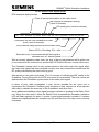
GEMINI2 Traffic Outstation Handbook
Siemens Mobility and Logistics, Traffic Solutions
Sopers Lane
Poole
Dorset
BH17 7ER
SYSTEM/PROJECT/PRODUCT: GEMINI2 Traffic Outstation
SIEMENS
GEMINI2
TRAFFIC OUTSTATION
HANDBOOK
Prepared: Paul Cox
Eric Burdis
Jim Ballantine
Mark Retallack
Function: Traffic Engineering
THIS DOCUMENT IS ELECTRONICALLY HELD AND APPROVED
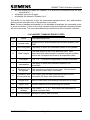
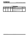
Issue
Change Ref.
Date
7
Mantis 6633,
6978
23-July-2009
TS004779
8
TS005210
22-February-2010
9
TS005647
29-November-2010
10
TS006234
09-November-2011
11
TS006588
09-July-2012
© Siemens plc 2010. All rights reserved.
The information contained herein is the property of Siemens plc and is supplied
without liability for errors or omissions. No part may be reproduced or used except as
authorised by contract or other written permission. The copyright and the foregoing
restriction on reproduction and use extend to all media in which the information may
be embodied.
667/HB/32600/000
Page 1
Issue 11
GEMINI2 Traffic Outstation Handbook
SAFETY WARNINGS
In the interests of health and safety, when using or servicing this equipment, the
following instructions must be noted and adhered to:
(i)
Only Skilled or Instructed personnel with relevant technical knowledge and
experience, who are also familiar with the safety procedures required when
dealing with modern electrical or electronic equipment, are to be allowed to
use and/or work on the equipment. All work shall be performed in accordance
with the Electricity at work Regulations 1989 and the relevant Highways
Agency (DoT) procedures of test and maintenance.
(ii)
Such personnel must take heed of all relevant notes, cautions and warnings in
this handbook, and any other documents and handbook associated with the
equipment including, but not restricted to, the following:
(a)
The equipment must be correctly connected to the specified incoming
power supply.
(b)
The equipment must be disconnected/isolated from the incoming power
supply before removing protective covers or working on any part from
which protective covers have been removed.
(c)
The equipment contains batteries that must be disposed of in a safe
manner. If in doubt of the correct procedure, refer to the Siemens
instructions.
667/HB/32600/000
Page 2
Issue 11
GEMINI2 Traffic Outstation Handbook
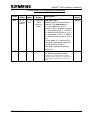
Maintenance Provision (MP)
1.
Product Reference
Siemens GEMINI2 Traffic Outstation
2.
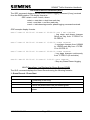
Specifications
The GEMINI2 Traffic Outstation is designed to meet the following Highways
Agency specifications:
MCE 0152
Monitoring and Control of Traffic Equipment via
the Public Switched Telephone Network.
MCE 0153
Functional Specification for the Monitoring and
Control of Variable Message Signs on Roads
Other Than Motorways
TR 2130, Issue C, Feb 2002
Environmental tests for motorway
communications equipment and portable and
permanent road traffic control equipment
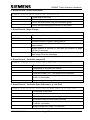
3.
Installation and Commissioning
Methods of Installation and Commissioning are detailed in the Siemens Traffic
Controls document:
667/HB/32600/000 GEMINI2 Traffic Outstation Handbook.
For Graphos, these methods are detailed in document 667/HB/31200/000
Graphos Product Handbook (Section 14 – Commissioning).
4.
Spares and Maintenance
All maintenance and repairs should be carried out in accordance with the
Siemens Traffic Controls document:
667/HB/32600/000 GEMINI2 Traffic Outstation Handbook.
For Graphos, see documents
667/HB/31200/000 Graphos Product Handbook, and
667/HE/31200/000 Fault Finding and Troubleshooting Guide.
5.
Modifications
There are no approved modifications, with the exception of those listed in the
following Siemens Traffic Controls Document:
667/HB/32600/000 GEMINI2 Traffic Outstation Handbook
667/HB/32600/000
Page 3
Issue 11
GEMINI2 Traffic Outstation Handbook
6.
Warning
Use of components other than those permitted above or modifications or
enhancements that have not been authorised by Siemens Traffic Controls
may invalidate Type Approval of this product.
MP 15/04/2003 Issue 1
667/HB/32600/000
Page 4
Issue 11
GEMINI2 Traffic Outstation Handbook
CONTENTS
1. INTRODUCTION .................................................................................................. 13
1.1 PURPOSE .......................................................................................................... 13
1.2 SCOPE ............................................................................................................... 13
1.3 RELATED DOCUMENTS ................................................................................... 13
1.4 ABBREVIATIONS .............................................................................................. 14
2. PRODUCT DESCRIPTION .................................................................................. 15
2.1 INTRODUCTION ................................................................................................ 15
2.2 SIEMENS GEMINI2 TRAFFIC OUTSTATION EQUIPMENT .............................. 18
2.2.1 The GEMINI2 Platform .............................................................................. 18
2.2.2 Basic OMCU ............................................................................................. 19
2.2.3 MOVA ....................................................................................................... 20
2.2.4 Bus Processing ......................................................................................... 21
2.2.5 UTMC Outstation ...................................................................................... 21
2.2.6 Graphos Outstation .................................................................................. 22
2.3 PROCESSOR UNIT ........................................................................................... 22
2.3.1 Processor Unit's Features ........................................................................ 22
2.4 LMU I/O BOARD ................................................................................................ 23
2.4.1 LMU I/O Board Features........................................................................... 23
2.4.2 3RD Party ELV AC LMU I/O Board ............................................................ 24
2.5 BUS / MOVA I/O BOARD ................................................................................... 24
2.5.1 BUS / MOVA I/O Board Features ............................................................. 25
2.6 THE MODEM UNIT ............................................................................................ 25
2.6.1 The PSTN Modem Unit............................................................................. 25
2.6.2 The GSM Modem Unit .............................................................................. 26
2.6.3 The PAKNET Modem Unit ........................................................................ 28
2.6.4 The DSL Modem Unit ............................................................................... 28
2.6.5 The MC35 GPRS Modem ......................................................................... 30
2.7 THE POWER SUPPLY UNIT (PSU) .................................................................. 30
2.7.1 The Power Supply Unit (PSU) Features ................................................... 30
2.8 THE EXPANSION BUS ...................................................................................... 31
2.8.1 The Expansion Bus Features ................................................................... 31
3. SPECIFICATIONS ............................................................................................... 32
3.1 INTRODUCTION ................................................................................................ 32
3.2 ELECTRICAL ..................................................................................................... 32
3.2.1 Mains Supply ............................................................................................ 32
3.2.2 Power Supply ........................................................................................... 32
3.2.3 Power Dissipation ..................................................................................... 33
3.2.4 Support Batteries ...................................................................................... 33
3.3 MECHANICAL .................................................................................................... 33
3.4 ENVIRONMENTAL ............................................................................................ 34
3.5 ISOLATED OUTPUTS ....................................................................................... 34
3.6 DIGITAL INPUTS ............................................................................................... 35
3.7 ISOLATED MAINS VOLTAGE INPUTS ............................................................. 35
3.8 3RD PARTY ELV AC INPUTS ............................................................................. 36
3.9 ANALOGUE INPUTS ......................................................................................... 36
3.10 COMMUNICATIONS ........................................................................................ 37
667/HB/32600/000
Page 5
Issue 11
GEMINI2 Traffic Outstation Handbook
3.10.1 Communications Channel 1 TR2210 (TR0141) Port .............................. 37
3.10.2 Communications Channel 2 (Modem Port) ............................................. 37
3.10.3 Communications Channel 3 (Handset) ................................................... 37
3.10.4 Communications Channel 4 (Ethernet) ................................................... 37
3.10.5 RS485 Communications Interfaces ........................................................ 37
3.10.6 RS232 Handset Interface ....................................................................... 39
4. FACILITIES .......................................................................................................... 40
4.1 INTRODUCTION ................................................................................................ 40
4.2 OMCU AND BUS PROCESSOR FACILITIES.................................................... 40
4.2.1 Signal Lamp Monitoring ............................................................................ 41
4.2.2 Detector and Push-Button Monitoring ....................................................... 41
4.2.3 Controller Status Checks .......................................................................... 42
4.2.4 Controller Timing Checks ......................................................................... 42
4.2.5 Bus Processor Functions .......................................................................... 42
4.2.6 ST800/700 Enhanced Link ....................................................................... 44
4.2.7 Car Park Count Detection ......................................................................... 46
4.2.8 PAKNET / GPRS interface ....................................................................... 46
4.2.9 DUSC Facility ........................................................................................... 47
4.2.10 Flow Facility ............................................................................................ 50
4.2.11 Occupancy Facility.................................................................................. 51
4.2.12 OMCU Events and Switch Override Facility ........................................... 51
4.2.13 SieClass Vehicle Classifier Facility ......................................................... 52
4.2.14 Graphos Facility ...................................................................................... 54
4.2.15 RMS Firmware Download Facility ........................................................... 57
4.3 UTMC FACILITIES ............................................................................................. 58
4.3.1 UTMC OTU Facility................................................................................... 58
4.3.2 UTMC VMS Facility .................................................................................. 59
4.4 GSM OMCU ....................................................................................................... 60
4.4.1 Remote Monitoring ................................................................................... 60
4.4.2 Bus Priority and Access Control ............................................................... 61
4.5 ETHERNET OMCU ............................................................................................ 61
5. INSTALLATION ................................................................................................... 63
5.1 INSTALLATION CHECK LIST ............................................................................ 63
5.1.1 Users Responsibilities .............................................................................. 64
5.1.2 UTMC OTU Installation Prerequisites ....................................................... 64
5.2 SET-UP .............................................................................................................. 70
5.2.1 I/O Board Position Selection (All Board Types) ........................................ 70
5.2.2 Modem Power Supply Selection (All Board Types) .................................. 71
5.2.3 50/60 Hz Operation .................................................................................. 74
5.2.4 120/230V AC Operation............................................................................ 74
5.2.5 RS485 Terminating Resistors (BUS / MOVA I/O Board Only) .................. 75
5.2.6 Output Resistor Options (BUS / MOVA & Digital I/O Boards Only) .......... 76
5.2.7 Welsh Office 50V – 0 – 50V Working (LMU I/O Board Only) .................... 76
5.2.8 RAM Battery Back-Up............................................................................... 77
5.3 INSTALLATION INTRODUCTION ..................................................................... 77
5.4 HARDWARE INSTALLATION ............................................................................ 77
5.4.1 General Installation ................................................................................... 77
5.4.2 Radio Clock Installation ............................................................................ 79
667/HB/32600/000
Page 6
Issue 11
GEMINI2 Traffic Outstation Handbook
5.5 CABLE AND WIRING ......................................................................................... 80
5.6 INTERFACING ................................................................................................... 80
5.6.1 Serial Linked ............................................................................................. 81
5.6.2 Freestanding............................................................................................. 81
5.6.3 CPU and BUS / MOVA (Digital) I/O .......................................................... 91
5.6.4 BUS / MOVA Board RS485 Serial Ports ................................................... 96
5.6.5 MOVA Digital I/O ...................................................................................... 97
5.6.6 Post Installation Checks ........................................................................... 97
5.6.7 Cable Form Identification .......................................................................... 98
5.6.8 TR0141 Cable Installation (Controller)...................................................... 98
5.6.9 TR0141 Cable Installation (OTU) ............................................................. 99
5.6.10 Mains Supply Connection ....................................................................... 99
5.6.11 Connect Unit Support Battery ............................................................... 100
5.6.12 Peek TRX Controller I/O connections ................................................... 100
5.7 INSTALLATION OF THE UNIT IN ADDITIONAL OUTERCASE ...................... 100
5.8 INSTALLATION OF THE GEMINI2 UPGRADE ................................................ 101
5.8.1 Additional Information for Old Installations ............................................. 101
6. TRAFFIC OUTSTATION COMMISSIONING ..................................................... 104
6.1 INTRODUCTION .............................................................................................. 105
6.2 OMCU, CAR PARK AND BUS PRIORITY COMMISSIONING CHECKLIST.... 105
6.3 VEHICLE CLASSIFIER, UTMC OTU AND VMS COMMISSIONING CHECKLIST
............................................................................................................................... 111
7. MAINTENANCE ................................................................................................. 117
7.1 INTRODUCTION .............................................................................................. 118
7.2 FIRST LINE ...................................................................................................... 118
7.3 FAULT FINDING .............................................................................................. 118
7.3.1 LED Indications ...................................................................................... 119
7.4 ROUTINE MAINTENANCE .............................................................................. 120
7.4.1 Annual Maintenance ............................................................................... 120
7.4.2 5-Yearly Maintenance ............................................................................. 121
7.5 PART NUMBERS ............................................................................................. 121
7.6 SPARES ........................................................................................................... 122
7.6.1 General ................................................................................................... 122
7.6.2 Interface Cables ..................................................................................... 123
7.6.3 Batteries ................................................................................................. 123
7.6.4 Fuses ...................................................................................................... 123
8. FAULT FINDING AND REPAIR......................................................................... 124
8.1 INTRODUCTION .............................................................................................. 124
8.2 BATTERY FAILURES ...................................................................................... 125
8.3 TELECOMMUNICATIONS APPROVAL WARNING ........................................ 125
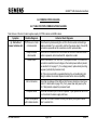
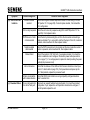
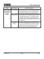
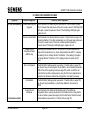
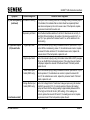
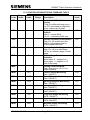
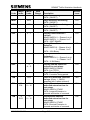
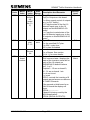
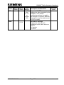
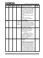
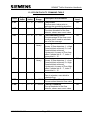
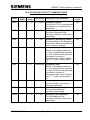
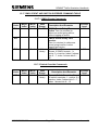
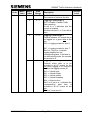
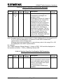
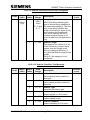
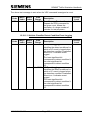
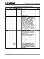
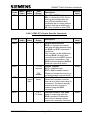
8.4 COMMUNICATIONS FAILURES ..................................................................... 126
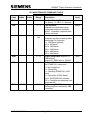
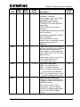
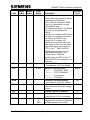
8.4.1 TABLE FOR PSTN COMMUNICATIONS FAILURES ............................ 126
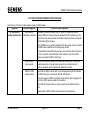
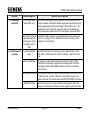
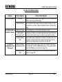
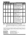
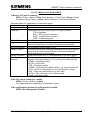
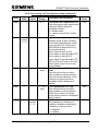
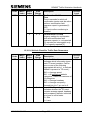
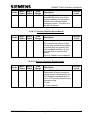
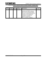
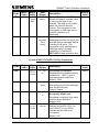
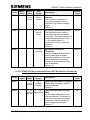
8.4.2 TABLE FOR GSM COMMUNICATIONS FAILURES .............................. 129
8.4.3 TABLE FOR PAKNET COMMUNICATIONS FAILURES ........................ 132
8.4.4 TABLE FOR UTMC COMMUNICATIONS FAILURES............................ 134
8.4.5 Modem Compatibility .............................................................................. 135
8.5 TABLE FOR EQUIPMENT FAILURES ............................................................. 136
8.6 TABLE FOR POWER FAILURES .................................................................... 139
667/HB/32600/000
Page 7
Issue 11
GEMINI2 Traffic Outstation Handbook
9. MOVA ................................................................................................................ 140
9.1 MOVA INTRODUCTION .................................................................................. 140
9.2 MOVA FREESTANDING INTERFACES .......................................................... 142
9.2.1 Detector Inputs and Push-Buttons .......................................................... 143
9.2.2 Confirms and Controller Ready Inputs .................................................... 144
9.2.3 Force Bits and Take Over Outputs ......................................................... 144
9.2.4 I/O Allocation .......................................................................................... 144
9.3 CONNECTION TO A SIEMENS T400.............................................................. 146
9.4 TELEPHONE LINE SHARING ......................................................................... 146
9.5 MOVA COMMISSIONING CHECKLIST ........................................................... 147
9.6 MOVA COMMISSIONING DETAIL .................................................................. 150
9.6.1 Communicating Locally with the MOVA Unit .......................................... 151
9.6.2 Complete Initialisation............................................................................. 152
9.6.3 Phone Line Sharing Facility (PLS) .......................................................... 152
9.6.4 Serial Link between MOVA and an ST800/700 (MIO) ............................ 153
9.6.5 MOVA Licence Codes ............................................................................ 154
9.6.6 Setting the Time and Date (CT) .............................................................. 155
9.6.7 Download New Site Data (RS, LD, CN and DS) ..................................... 156
9.6.8 Commissioning Screen (LOOK) ............................................................. 158
9.6.9 The Error Log (DE and CE) .................................................................... 160
9.6.10 Enabling MOVA Control........................................................................ 161
9.6.11 Modem Commissioning ........................................................................ 162
9.6.12 Completing MOVA Commissioning....................................................... 162
9.7 MOVA COMMUNICATIONS NOTES ............................................................... 163
9.7.1 Communicating Remotely....................................................................... 163
9.7.2 MOVA Flags (LF and SF) ....................................................................... 164
9.7.3 Phone Home Flag ................................................................................... 165
9.7.4 View MOVA Messages (VM) .................................................................. 166
9.7.5 Other Menu Options ............................................................................... 166
9.7.6 MOVA Detector Status Output................................................................ 167
9.8 DUAL STREAM MOVA .................................................................................... 167
9.8.1 Operator Interface .................................................................................. 167
9.8.2 Serial Interface to Controller ................................................................... 169
9.8.3 Parallel Interface ..................................................................................... 170
9.8.4 Advanced Programming of Stage Confirms with a Serial Interface to the
Controller ......................................................................................................... 173
9.8.5 Stream Interdependency ........................................................................ 174
9.9 MOVA 6 ENHANCEMENTS ............................................................................. 175
10. CAR PARKS .................................................................................................... 176
10.1 OVERVIEW .................................................................................................... 176
10.2 OUTSTATION STATUS MESSAGE TO SIESPACE ...................................... 177
10.2.1 Routine Poll .......................................................................................... 177
10.2.2 Loss of comms to PAKNET pad ........................................................... 177
10.2.3 Loss of Comms to GPRS Modem ......................................................... 178
10.3 DIFFERENCE COUNT AND THRESHOLDS ALGORITHM........................... 178
10.4 CONFIGURATION ......................................................................................... 181
10.4.1 Car Park Configuration ......................................................................... 181
10.4.2 Detector Fault Monitoring ..................................................................... 181
10.4.3 PAKNET Configuration ......................................................................... 182
667/HB/32600/000
Page 8
Issue 11
GEMINI2 Traffic Outstation Handbook
10.4.4 GPRS Configuration ............................................................................. 182
10.5 INSTALLATION .............................................................................................. 183
10.5.1 PAKNET Interface Connector ............................................................... 183
10.5.2 PAKNET Radio Pad Power .................................................................. 183
10.5.3 Door Switch .......................................................................................... 184
10.5.4 Count Detector Loops ........................................................................... 184
10.5.5 GPRS Modem Based Systems ............................................................. 184
10.6 APT SKIDATA INTERFACE ........................................................................... 184
10.6.1 Information required from APT Skidata................................................. 185
10.6.2 Configuration Handset commands ....................................................... 186
11. UTMC OTU ...................................................................................................... 187
11.1 INTRODUCTION ............................................................................................ 187
11.2 CONFIGURATION OF A FREESTANDING UTMC OTU INSTALLATION ..... 187
11.2.1 Configuration Data ................................................................................ 188
11.2.2 Example Configuration Commands ...................................................... 190
11.3 CONFIGURATION OF A SEMI-INTEGRAL UTMC OTU INSTALLATION ..... 195
11.3.1 Configuration Data ................................................................................ 196
11.3.2 Example Configuration Commands ...................................................... 196
11.4 INITIALISING THE OTU ................................................................................. 199
12. UTMC VMS ...................................................................................................... 200
12.1 INTRODUCTION ............................................................................................ 200
12.2 UTMC VMS CONFIGURATION ..................................................................... 200
12.2.1 Configuration Commands ..................................................................... 201
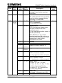
13. HANDSET FACILITIES ................................................................................... 204
13.1 INTRODUCTION ............................................................................................ 204
13.1.1 Command Format ................................................................................. 212
13.1.2 Display Format ..................................................................................... 213
13.1.3 Read Procedure (Monitor Existing Data) .............................................. 213
13.1.4 Write Procedure (Change Existing Data) .............................................. 214
13.1.5 Alternative Write Procedure (Change Data Following Read) ................ 214
13.1.6 Switchable Handset Facility .................................................................. 215
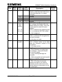
13.2 HANDSET COMMAND ERROR CODES ....................................................... 216
13.3 CONTROLLER MONITORING COMMAND TABLE ...................................... 217
13.4 INPUT MONITORING COMMAND TABLE .................................................... 220
13.4.1 Outstation Logical Input Ports (LIP) ...................................................... 221
13.5 LAMP MONITORING COMMAND TABLE ..................................................... 222
13.6 FAULT DATA COMMAND TABLE ................................................................. 224
13.6.1 Fault Diagnostics (FDC) ....................................................................... 225
13.6.2 General Fault Data Display Format ...................................................... 226
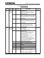
13.6.3 Green Conflict Fault Data (FLT CFL) .................................................... 232
13.6.4 Ignoring Demands Fault (FLT CID) ...................................................... 232
13.6.5 Dim/Bright Fault (FLT DBF) .................................................................. 232
13.6.6 Equipment Data Invalid Fault (FLT EDI) ............................................... 233
13.6.7 External Signal Active / Inactive Fault (FLT ESA / ESI) ........................ 233
13.6.8 Ferranti TSC Fault Data (FLT FFL) ...................................................... 233
13.6.9 GEC 3000 Fault Data (FLT GFL) .......................................................... 234
13.6.10 GPS Fault (FLT GPS) ......................................................................... 235
13.6.11 Mode Change Fault (FLT MCH) ......................................................... 235
667/HB/32600/000
Page 9
Issue 11
GEMINI2 Traffic Outstation Handbook
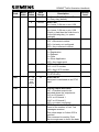
13.6.12 Stage Sequence Fault (FLT SEQ) ...................................................... 236
13.6.13 Site Power Fail/Clearance (FLT SOF/SON) ....................................... 236
13.6.14 Controller Stuck Fault (FLT STK) ....................................................... 236
13.6.15 Vehicle Absence Failure (FLT VAF) ................................................... 237
13.6.16 Vehicle Presence Failure (FLT VPF) .................................................. 237
13.6.17 Variable Message Sign Faults (FLG VMC, VMS) ............................... 237
13.6.18 Peek PTC1 Fault Data (FLT TFL) ....................................................... 238
13.7 PSTN COMMAND TABLE.............................................................................. 239
13.7.1 Call Disconnect Cause Statistics Log (CDC) ........................................ 241
13.7.2 Call Termination Record (CTR) ............................................................ 242
13.7.3 Modem Control Indicators (MCI) ........................................................... 242
13.7.4 Message Diagnostic Data (MDC) ......................................................... 243
13.7.5 Modem Power Cycle (MPC) ................................................................. 244
13.8 MAINTENANCE COMMAND TABLE ............................................................. 245
13.8.1 Outstation I/O Port State (IOP) ............................................................. 250
13.8.2 Outstation Operating Mode (OPM) ....................................................... 250
13.8.3 Outstation Power-Up Data (PUD) ......................................................... 251
13.8.4 Soft Error Buffer (SEB) ......................................................................... 251
13.8.5 Radio Clock Signal (RCS) .................................................................... 252
13.8.6 Green Record Command (GRC) .......................................................... 253
13.8.7 Operations Log Displays for Green Record (OLG) ............................... 253
13.8.8 RMS 8-Bit Comms ................................................................................ 255
13.9 BUS OPERATING COMMAND TABLE .......................................................... 256
13.9.1 Operations Log Display Formats (OLG) ............................................... 259
13.10 BUS CONFIGURATION COMMAND TABLE ............................................... 262
13.10.1 Generic Commands ............................................................................ 262
13.10.2 TfL Beacon Commands ...................................................................... 265
13.10.3 SIETAG Commands ........................................................................... 267
13.10.4 RTIG Commands ................................................................................ 270
13.11 BUS CONFIGURATION NOTES.................................................................. 273
13.12 CAR PARK COUNT COMMAND TABLE ..................................................... 274
13.13 PAKNET/GPRS COMMAND TABLE ............................................................ 279
13.14 DUSC COMMAND TABLE ........................................................................... 281
13.14.1 CLF Operating Commands ................................................................. 281
13.14.2 Accessing CLF Configuration Data Commands ................................. 285
13.14.3 CLF Time Commands......................................................................... 291
13.15 FLOW FACILITY COMMAND TABLE .......................................................... 293
13.16 OCCUPANCY FACILITY COMMAND TABLE.............................................. 294
13.17 OMCU EVENT AND SWITCH OVERRIDE COMMAND TABLE .................. 295
13.17.1 OMCU Events Commands ................................................................. 295
13.17.2 Switch Override Commands ............................................................... 295
13.18 VEHICLE CLASSIFIER COMMAND TABLE ................................................ 296
13.18.1 Vehicle Classifier Common Configuration .......................................... 296
13.18.2 Operations Log Capacity .................................................................... 307
13.18.3 Operations Log Display Formats (OLG) ............................................. 307
13.19 UTMC GENERAL COMMAND TABLE ......................................................... 310
13.20 UTMC OTU COMMAND TABLE .................................................................. 314
13.20.1 UTMC OTU Communication Set-Up Commands ............................... 314
13.20.2 UTMC OTU Control and Reply Bit Allocation Commands .................. 315
13.20.3 UTMC OTU Diagnostic Display Commands ....................................... 322
667/HB/32600/000
Page 10
Issue 11
GEMINI2 Traffic Outstation Handbook
13.20.4 UTMC OTU Test / Maintenance Commands ...................................... 324
13.20.5 UTMC OTU Output Override Commands ........................................... 325
13.20.6 UTMC OTU HIOCC Facility Commands ............................................. 326
13.20.7 UTMC OTU Environmental Sensor/SIETAG Interface Commands .... 327
13.20.8 UTMC OTU Engineering Commands ................................................. 328
13.21 UTMC VMS COMMAND TABLE .................................................................. 329
13.21.1 UTMC VMS Common Configuration ................................................... 329
13.21.2 UTMC VMS Sign Control Configuration.............................................. 329
13.22 GRAPHOS COMMAND TABLE ................................................................... 331
Appendix A MOVA INSTALLATION SHEETS ..................................................... 335
Appendix B GEMINI2 DRAWINGS ....................................................................... 339
B.1 INTRODUCTION ............................................................................................. 339
B.2 DRAWING LIST ............................................................................................... 339
Appendix C GNU Open Software License .......................................................... 341
Appendix D MOVA 4 and 5 .................................................................................. 346
D.1 COMPLETE INITIALISATION.......................................................................... 346
D.2 DOWNLOAD NEW SITE DATA (RS, LD, CN AND DS) .................................. 347
D.3 COMMISSIONING SCREEN (LOOK).............................................................. 350
INDEX .................................................................................................................... 354
667/HB/32600/000
Page 11
Issue 11
GEMINI2 Traffic Outstation Handbook
TABLE OF FIGURES
Figure 1 – Overview ................................................................................................. 15
Figure 2 – Basic OMCU to ST700 or ST800 ............................................................ 19
Figure 3 – Basic OMCU to Any Other Controller ...................................................... 19
Figure 4 – MOVA to ST700 or ST800 ...................................................................... 20
Figure 5 – MOVA to Any Other Controller ................................................................ 20
Figure 6 – BUS Processing to Any Controller .......................................................... 21
Figure 7 – UTMC OTU to ST700 or ST800 .............................................................. 21
Figure 8 – UTMC OTU to Any Other Controller ........................................................ 22
Figure 9 – SIETAG OMCU to OTU .......................................................................... 43
Figure 10 – Force Bit Control Set-up ........................................................................ 48
Figure 11 – ST800/700 Enhanced Serial Link Control Set-up .................................. 49
Figure 12 – Detector Control Set-up......................................................................... 50
Figure 13 – Graphos block diagram ......................................................................... 56
Figure 14 – Freestanding UTMC OTU Set-up .......................................................... 58
Figure 15 – ST800/700 Semi-Integral UTMC OTU Set-up ....................................... 59
Figure 16 – UTMC VMS System Overview .............................................................. 60
Figure 17 – I/O Board ............................................................................................... 71
Figure 18 – Radio Clock Unit ................................................................................... 80
Figure 19 – Current Sensor Connection ................................................................... 83
Figure 20 – Typical Green State Connections .......................................................... 87
Figure 21 – Dual Stream MOVA Stage Confirm Bit Field Designation ................... 169
Figure 22 – Dual Stream MOVA Force Bit Field Designation ................................. 170
Figure 23 – BUS/MOVA Card Pinout ..................................................................... 171
Figure 24 – Stage Confirm Allocation - Advanced Use .......................................... 173
Figure 25 – MOVA End Saturation Conditioning Word........................................... 174
Figure 26 – Extrapolation ....................................................................................... 180
LAST PAGE ........................................................................................................... 367
667/HB/32600/000
Page 12
Issue 11
GEMINI2 Traffic Outstation Handbook
1. INTRODUCTION
1.1 PURPOSE
This document is intended to provide sufficient information to the user to install,
configure and maintain the GEMINI2 Traffic Outstation, either as a Siemens RMS
OMCU, a Bus Processor, a Siemens MOVA unit, a SieClass (Vehicle Classifier) unit,
a UTMC OTU, a VMS unit or a Graphos unit.
The GEMINI2 Traffic Outstation is based on the original GEMINI Traffic Outstation
with an upgraded processor card containing additional memory. The GEMINI2 Traffic
Outstation provides additional functionality in terms of dual-stream MOVA 5 and
future expansion capability. See section 2.2.1 for additional information.
1.2 SCOPE
This document covers the Siemens OMCU, Bus Processor, MOVA, SieClass, UTMC
OTU and UTMC VMS units.
This document does not include any details about:
(a) MOVA strategy or how to generate the MOVA configuration. For details about
MOVA strategy and for more information about the operation of the MOVA unit, refer
to the MOVA documents listed below.
(b) The Graphos equipment or how to set up the Graphos configuration. For more
information about the operation of the Graphos unit, refer to the Graphos documents
listed below.
1.3 RELATED DOCUMENTS
GEMINI Traffic Outstation Handbook ............................................. 667/HB/30600/000
RMS Instation Users Handbook ..................................................... 667/HB/26131/000
RMS DUSC Users Handbook ........................................................ 667/HB/26131/100
TC12 Installation, Commissioning and Maintenance Handbook .. 667/HE/43100/000
Installation, Commissioning of GPRS Siespace Systems ............. 667/HE/30707/000
Monitoring and Control of Traffic control equipment via the PSTN .............. MCE 0152
Monitoring and Control of Variable Message Signs on Roads other than Motorways
.................................................................................................................... MCE 0153
TRL MOVA Traffic Control Manual ...................................................................... AG10
TRL MOVA Data Set-Up Guide .......................................................................... AG11
TRL MOVA Equipment User Guide ..................................................................... AG12
Installation Guide for MOVA (Issue B, December 1999) ............................. MCH 1542
Graphos Product Handbook ........................................................... 667/HB/31200/000
667/HB/32600/000
Page 13
Issue 11
GEMINI2 Traffic Outstation Handbook
Fault Finding and Troubleshooting Guide Handbook ..................... 667/HE/31200/000
1.4 ABBREVIATIONS
AC
CCITT
CLF
CPU
DC
DFM
DUSC
EMC
FLASH
GPRS
Graphos
GSM
I/O
LAN
LED
LMU
MOVA
OEM
OMU
OMCU
OTU
PCB
PIN
PROM
PSTN
PSU
RAM
RMS
RS232
RS485
SCOOT
STC
TfL
TRL
UTC
UTMC
UVMS
VC
Alternating Current
International Co-ordinating Committee for Telephony and Telegraphy
Cable-less Linking Facility
Central Processing Unit
Direct Current
Detector Fault Monitoring
Dial Up Strategic Control
Electromagnetic Compatibility
Non-volatile memory that may be programmed under software control
General Packet Radio System
Graphical Variable Message Sign / Vehicle Activated Sign
Global System for Mobile communication
Input and Output
Local Area Network
Light Emitting Diode
Lamp Monitoring Unit
Microprocessor Optimised Vehicle Actuation
Other Electrical Manufacturers
Outstation Monitoring Unit
Outstation Monitoring and Control Unit
Outstation Transmission Unit
Printed Circuit Board
Personal Identification Number
Programmable Read Only Memory
Packet Switched Telephone Network
Power Supply Unit
Random Access Memory
Root Mean Square or Remote Monitoring System
EIA Data Communications Interface - Level based serial
communications standard
EIA Differential Data Communications Interface - Differential serial
communications standard
Split, Cycle, Offset, Optimisation Technique
Siemens Traffic Controls
Traffic for London
Transport Research Laboratory
Urban Traffic Control
Universal Traffic Management and Control
Urban Variable Message Sign
Vehicle Classification
667/HB/32600/000
Page 14
Issue 11
GEMINI2 Traffic Outstation Handbook
2. PRODUCT DESCRIPTION
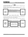
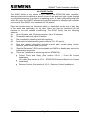
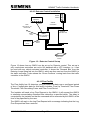
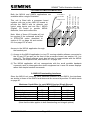
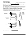
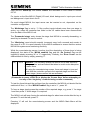
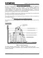
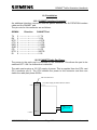
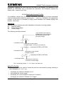
2.1 INTRODUCTION
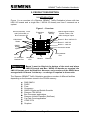
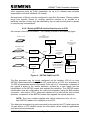
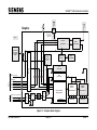
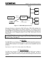
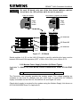
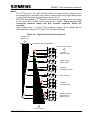
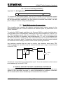
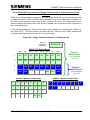
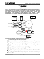
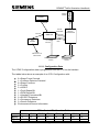
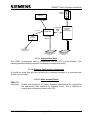
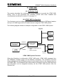
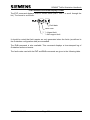
Figure 1 is an overview of a Siemens GEMINI2 Traffic Outstation (shown with two
LMU I/O boards and a single Bus / MOVA I/O board) and how it connects as a
system.
Figure 1 – Overview
MOVA Detectors, Force
and Confirm Bits, or
Bus Processor I/O
Expansion
Bus
RS485 to
SIETag
LMU Mains’
States
OMCU Digital Outputs,
Modem Power, and
LMU Analogue inputs
Board 3 - Bus / MOVA I/O
Board 2 - LMU I/O
Board 1 - LMU I/O
OMCU
Digital
Inputs
Processor Board
PSU and BATTERY
Local Handset
Port
Mains
To Controller
Handset Port
Telephone
Line
Modem
Ethernet
Board 1 must be fitted at the bottom of the stack and where
LMU I/O boards and Bus / MOVA I/O boards are required, the
LMU I/O boards must be fitted first. However, early versions of the OMCU were
arranged with I/O board 1 at the top – no change is required to these units.
Important
The Siemens GEMINI2 Traffic Outstation provides a number of different facilities
depending on the firmware stored in the FLASH memory:
RMS OMCU
DUSC
Flow
Occupancy
OMCU Events and Switch Override
Siemens TRL MOVA
Bus Processor applications
Siemens Vehicle Classifier (SieClass)
Car Park Count application
UTMC OTU
Graphos
667/HB/32600/000
Page 15
Issue 11
GEMINI2 Traffic Outstation Handbook
The RMS OMCU application monitors TR2210 intersection and ‘mid-block’ (or
‘stand-alone’) pedestrian controllers and most pre-TR0141/TR2210 traffic controllers.
It reports back faults and status of both the Traffic Controller and the OMCU itself to
the Instation. The configuration for the intersection to be monitored is downloaded
from the Instation to the OMCU. See section 4.1 for more information on the OMCU
application.
The DUSC application has the same facilities as the RMS OMCU application, but
can also control traffic controllers via timetable events (e.g. introduce a plan at 9am
on Monday, and isolate the plan at 6pm on Friday). See section 4.2.9 for more
information on the DUSC application.
The Flow application can be connected to up to 16 detectors. Each detector can
provide flow data over a configured period of time. If the flow data meets the ‘up
threshold’, a flow alarm is raised. If the flow data meets the ‘down threshold’, the flow
alarm is cleared. Flow data is stored in the ‘Operations Log’, and can be uploaded to
the RMS Instation. See section 4.2.10 for more information on the Flow application.
The Occupancy application can be connected to up to 16 detectors. Each detector
can provide occupancy data over a configured period of time. If the occupancy data
meets the’ up threshold’, an occupancy alarm is raised. If the occupancy data meets
the ‘down threshold’, the occupancy alarm is cleared. Occupancy data is stored in
the ‘Operations Log’, and can be uploaded to the RMS Instation. See section 4.2.11
for more information on the Occupancy application.
There are up to 16 OMCU Events, which are inputs to the OMCU and 16 Switch
Overrides, which are outputs from the OMCU. The OMCU Events are monitored and
when they meet predefined conditions a message is sent to the Instation. The
Instation can then make a decision as to whether a new plan and/or switch should be
introduced (Switch Overrides). By adjusting plans and/or switches at adjacent traffic
junctions the traffic flows within an area can achieve an increased flow capacity.
Switch Overrides are activated by the Instation when an OMCU Event has been
reported. A Switch Override will remain active for a fixed period of time, or until
cancelled by the Instation. See section 4.2.12 for more information on the OMCU
Events and Switch Override Facility.
The Bus Processor application can be connected to up to 12 SIETAG readers, TfL
microwave beacons or a single TfL RTIG radio link. The application provides both
logging and access control functions. See section 4.2.5 for more information on the
Bus Processor Functions.
The MOVA application is a new strategy for control of traffic light signals at isolated
junctions. See section 9 for more information on the MOVA application.
The Car Park application determines the current occupancy of a car park and sends
this to a ‘SIESpace’ Instation over a PAKNET communications interface. This
information can then be used by the Instation to guide vehicles to car parks that have
spaces. See section 10 for more information on the Car Park application.
667/HB/32600/000
Page 16
Issue 11
GEMINI2 Traffic Outstation Handbook
The UTMC OTU enables second-by-second control of the associated Traffic
Controller by the central UTC system, using open-standard protocols. See section
2.2.5 for outline layout, section 4.3.1 for overview, section 5.1.2 for installation prerequisites and cabling, and section 11 for configuration details.
The Graphos application is a new strategy for control of a cluster of Signs (up to 4
signs). See section 4.2.14 for more information on the Graphos application.
All of the applications within a unit (except the Car Park and the Graphos application)
can be used simultaneously; limited only by the number of I/O boards that can be
accommodated, and by the availability of the appropriate communications to the
relevant instation system.
The hardware platform is a self contained unit consisting of a CPU board that is
microprocessor based; one or more I/O Boards, the PSU, Battery and optionally a
Modem (see Figure 1 overleaf).
Note: Graphos has no I/O boards and uses a different PSU.
Where a Modem is present, it can be connected through a land line to the PSTN or
via a GSM 900 digital network. The unit can be communicated with and will report
back faults via the PSTN or GSM. When a modem is not present, all Instation
functions are available locally via a local RS232 ‘handset’ port. The platform has the
facility to share a PSTN connection with other compatible equipment. The GSM
version of the unit is available for situations where a PSTN connection is not
available or is not cost effective (see sections 2.6.2 and 4.2.9).
The unit is mains powered and is fitted with a battery to support the unit in the event
of a mains failure. This allows it to dial the Instation to report the mains failure.
The complete unit fits within a Traffic Controller’s Roadside Cabinet. It is designed to
fit within an existing 3U detector rack, in an additionally supplied 3U rack, or directly
onto the rack mounting uprights. It can be mounted in an ancillary housing if
necessary.
When fully configured it occupies 192mm of a standard 3U rack, and is of a modular
design. The boards are interconnected by way of an expansion bus and up to 3 I/O
boards may be fitted. The main features of each individual board, assembly and the
expansion bus are highlighted in the following sections.
This Unit meets all the Environmental and EMC requirements as specified in MCE
0152A, MCE 0153A and specifications TR2130C and EN50293.
667/HB/32600/000
Page 17
Issue 11
GEMINI2 Traffic Outstation Handbook
2.2 Siemens GEMINI2 Traffic Outstation Equipment
2.2.1 The GEMINI2 Platform
The GEMINI2 Traffic Outstation is based on the original GEMINI Traffic Outstation
with an upgraded processor card containing additional memory and a new version of
firmware. The GEMINI2 Traffic Outstation provides additional functionality in terms of
dual-stream MOVA 5 and future expansion capability.
Compatibility
The GEMINI2 Traffic Outstation is compatible with I/O boards and expansion kits as
supplied with the original GEMINI Traffic Outstation.
Identification
The GEMINI2 Traffic Outstation can be identified by the Gemini2 logo on the PSU
front panel. In addition, the GEMINI2 processor board is variant 999, as identified on
the right hand portion of the processor board serial number/bar code label
e.g. 999-01 identifies processor board variant 999, issue 1.
Firmware
The GEMINI2 Traffic Outstation runs a new version of firmware – latest part number
12687. The part number and issue state can be displayed on the handset using the
‘PIC’ command. The GEMINI2 Traffic Outstation can run firmware PB684 or PB683 if
required.
IMPORTANT: The new GEMINI2 firmware will not run on the original GEMINI Traffic
Outstation.
Top Level Variant Numbering
The GEMINI2 Outstation top level part numbers are now 667/1/32600/xxx, whereas
the original GEMINI Outstation part numbers were 667/1/30600/xxx. The /xxx variant
code remains the same, thus the original number 667/1/30600/001 becomes
667/1/32600/001 for GEMINI2. See section 7.5 for a full list.
Outstation Equipment Options
The Siemens OMCU (667/1/32600/001) together with the associated OMCU cables
is capable of monitoring a Traffic controller with up to 16 phases and up to 48 digital
inputs. It can also control a number of isolated outputs.
The OMCU normally uses one or more LMU I/O boards each providing up to 10
lamp monitor channels, 16 digital inputs, and 4 digital outputs. An alternative I/O
board providing 4 RS485 communication channels, 48 digital inputs and 16 digital
outputs may also be fitted. This board is primarily used by the Bus Processor and
MOVA applications and thus is known as the Bus / MOVA I/O board.
667/HB/32600/000
Page 18
Issue 11
GEMINI2 Traffic Outstation Handbook
A number of optional kits are available which, when added to the Basic OMCU, allow
connection to any Controller. MOVA and BUS Processing kits are also available. The
sections 2.2.2 etc. that follow show the combinations of facilities and the way the
components are connected.
It is also possible to upgrade an existing “old style” OMU/MOVA/Bus Processor with
a new GEMINI2 processor card to provide all the new facilities described in this
handbook. The installation details for this are described in section 5.8.
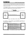
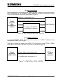
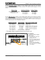
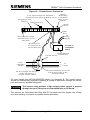
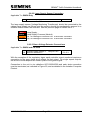
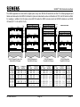
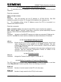
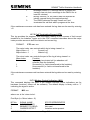
2.2.2 Basic OMCU
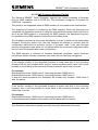
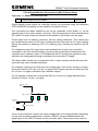
The PSTN GEMINI2 Traffic Outstation OMCU (667/1/32600/001) can be used with
an ST700 or ST800 Controller. See Figure 2 below for details.
Traffic
Outstation
(OMCU)
TR0141 Cable – see Section 5.6.8
ST700 or
ST800
Controller
Figure 2 – Basic OMCU to ST700 or ST800
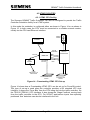
For connection to other Controllers, use the OMCU/LMU I/O Expansion kit
(667/1/28853/001). If additional I/O is required, also add the OMCU / LMU I/O
Expansion kit (667/1/28853/000).
Current Sensor – see Section 5.6.2.1
Lamp Supply Sensor – see Section 5.6.2.2
Traffic
Outstation
(OMCU)
Lamp Supply Cable – see Section 5.6.2.3
Any Other
Controller
Digital Monitor Connection – see Section 5.6.2.4
TR0141 Cable – see Section 5.6.8
Figure 3 – Basic OMCU to Any Other Controller
667/HB/32600/000
Page 19
Issue 11
GEMINI2 Traffic Outstation Handbook
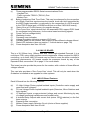
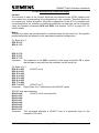
2.2.3 MOVA
2
A standard PSTN GEMINI Traffic Outstation will function as a MOVA unit if the
appropriate ‘enable code’ is used.
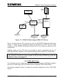
See Figure 4 below for details of the MOVA connections to an ST700 or ST800
Controller; connections to all other controllers are shown in Figure 5.
Lamp Supply Cable – see Section 5.6.2.3
Traffic
Outstation
(MOVA)
TR0141 Cable – see Section 5.6.8
ST700 or
ST800
Controller
Figure 4 – MOVA to ST700 or ST800
The MOVA unit described in Figure 4 may be used with other types of Controllers by
adding the MOVA I/O All Controller kit (667/1/28855/001).
If OMCU functionality is required in addition to MOVA, also add the cable kit(s)
described in Figure 3.
MOVA Detectors, Force and Confirm Bits – see
Section 9.2.4
Traffic
Outstation
(MOVA +
OMCU)
As Figure 3 if OMCU
functionality is required.
Any Other
Controller
Figure 5 – MOVA to Any Other Controller
667/HB/32600/000
Page 20
Issue 11
GEMINI2 Traffic Outstation Handbook
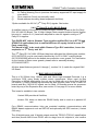
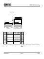
2.2.4 Bus Processing
Bus Processing may be performed by adding the Bus / MOVA I/O card and Cable kit
(667/1/28856/000) to the GEMINI2 Traffic Outstation. If OMCU functionality is also
required, also add the cable kit(s) described in Figure 3.
Digital I/O – see Section 5.6.3
RS485 to Reader/Beacon/RTIG – see Section 5.6.4
Traffic
Outstation
(Bus
Processing +
OMCU)
Any Controller
As Figure 3 if OMCU
functionality is required.
Figure 6 – BUS Processing to Any Controller
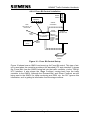
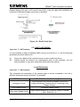
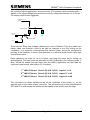
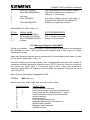
2.2.5 UTMC Outstation
A standard GEMINI2 Traffic Outstation will function as a UTMC Outstation if the
appropriate ‘enable code’ is used.
See Figure 7 below for details of the UTMC OTU connections to an ST700 or ST800
Controller; connections to all other controllers are shown in Figure 8.
Traffic
Outstation
(UTMC OTU)
TR0141 Cable – see Section 5.6.8
ST700 or
ST800
Controller
For configuration, see section 11.3
Figure 7 – UTMC OTU to ST700 or ST800
667/HB/32600/000
Page 21
Issue 11
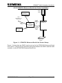
GEMINI2 Traffic Outstation Handbook
The UTMC Outstation unit described in Figure 7 may be used with other types of
Controllers by adding the UTMC O/S Kit (667/1/30625/000).
Traffic
Outstation
(UTMC OTU)
UTMC Detectors, Force and Confirm Bits – see
Section 11.2
Any Other
Controller
Figure 8 – UTMC OTU to Any Other Controller
2.2.6 Graphos Outstation
The Graphos Outstation consists of only the Gemini2 CPU Card, the battery and a
PSU which is different to the one normally used within a standard GEMINI2 Traffic
Outstation. It will function as a Graphos Outstation if the appropriate ‘enable code’ is
used.
See the Graphos Product Handbook 667/HB/31200/00 for more information.
2.3 PROCESSOR UNIT
This is a 3U 220mm long, 100mm wide and 17mm high extended Eurocard. It is a
multi-layer PCB, using mostly surface mount components. It provides the processing
power required by the unit. The processor unit is based on Motorola's Power PC
range of 32-bit microprocessors (MPC850) with highly sophisticated on-chip
peripheral capabilities. This offers much more capability with ‘built-in’ serial and
Ethernet ports.
The board provides the expansion bus that extends the system using one, two or
three I/O boards. For details see section 2.8 on page 31.
2.3.1 Processor Unit's Features
(a)
(b)
Battery backup of the entire RAM (see Section 7.6.3(b) on page 123). For Bus
Processor applications this board also provides capacitive support allowing
the RAM backup battery to be changed without loss of data.
The Expansion Bus for fast board to board data transfers. The CPU board can
address up to 3 I/O boards.
667/HB/32600/000
Page 22
Issue 11
GEMINI2 Traffic Outstation Handbook
(c)
(d)
(e)
(f)
(g)
(h)
(i)
(j)
(k)
(l)
(m)
Three programmable RS232 Serial communications Ports:
- Handset Port.
- Traffic controller TR2210 (TR0141) Port.
- Modem Port.
Battery backed-up Real Time Clock. This may be enhanced by the connection
of a Radio Clock that synchronises the internal clock with time transmitted by
the MSF Rugby transmitter (or optionally by the connection of a GPS receiver
to the TR2210 serial port (or RS485 serial port on a Bus / MOVA IO board)).
‘State of the art’ FLASH memory for program storage
‘Zero-Cross Over’ signal derived from the associated PSU support PCB. Used
for a software timing reference, for the mains based monitoring signals.
Power Fail (low voltage inhibit)
Watchdog monitor
Processor error indication
Voltage Regulation (allowing a range of DC input)
Provides power for the modem, with a choice of two different voltages offered.
Status LED indicators (also see section 7.3 which starts on page 118)
Power dissipation less than 100 mW.
2.4 LMU I/O BOARD
This is a 3U 220mm long, 100mm wide and 14mm high extended Eurocard. It is a
multi-layer PCB, using mostly surface mount components. When required for OMCU
monitoring, up to three LMU I/O boards may be fitted to meet the entire controller's
monitoring requirements. I/O boards access the processor board by way of the
Expansion Bus; see section 2.8 on page 31 for more details.
This board can also provide the power for the modem, with a choice of three different
voltages offered.
This card also provides a ‘Zero Cross Over’ circuit. This will only be used when the
Outstation is installed as an upgrade for older systems.
2.4.1 LMU I/O Board Features
Each I/O board has the following features:
(a)
(b)
(c)
(d)
(e)
(f)
(g)
10 High Voltage Photo-coupled Isolated Inputs (Controller mains supply and
green and wait voltages).*
16 Low Voltage Photo-coupled Isolated Inputs (Detectors, Micro Switches and
logic signals)
10 Analogue Inputs, surge protected (voltage and current Monitoring by way
of voltage monitoring transformers and toroidal coils).
4 Isolated Relay Outputs with current limit (series 182 resistors) on the first
three outputs.
Expansion Bus connection
Modem Power supply Selection Circuit (choice of three supplies)
Power dissipation less than 50 mW.
667/HB/32600/000
Page 23
Issue 11
GEMINI2 Traffic Outstation Handbook
(h)
(i)
(j)
5V Failing Warning Circuit (monitors the battery supported DC input supply for
a low level).
Zero crossover Circuit (not normally used).
Board address decoding (board expansion facilities).
*Option available for 48V AC (3RD Party ELV) signals. See below.
2.4.2 3RD Party ELV AC LMU I/O Board
A modified version of the LMU I/O Board has been created, known as the 3RD Party
ELV AC LMU I/O Board. The 10 High Voltage Photo-coupled Isolated Inputs (feature
list point ‘a’, section 2.4.1) have been adjusted to cater for signals running on 3RD
Party ELV supplies.
This DOES NOT refer to Siemens Type negative rectified ELV (as in ST750 and
ST900 ELV applications) but to nominal 48Vrms AC supply found in some 3RD
Party controllers.
This board is NOT to be used within Siemens Type ELV controllers, hence the
emphasis on ‘3RD Party’ and ‘AC’.
The 3RD Party ELV AC LMU I/O Board has been allocated the following part number,
667/1/26570/100, and is most easily identified by it’s ‘ELV ONLY’ warning labels
(667/2/32365/000) affixed to the boards two protective cover guards. For clarification
on the location of these cover guards, please refer to assembly drawing
667/GA/26570/ETC.
All other board features (points ‘b’ through ‘j’, section 2.4.1) match the original LMU
I/O Board.
2.5 BUS / MOVA I/O BOARD
This is a 3U 220mm long, 100mm wide and 18mm high extended Eurocard. It is a
multi-layer PCB, using mostly surface mount components. When used for Bus
Processor or MOVA applications, the unit can be fitted with up to three Bus / MOVA
I/O boards. If OMCU monitoring functions are also required, then a mix of LMU I/O
boards and Bus / MOVA I/O boards can be fitted. I/O boards access the processor
board by way of the Expansion Bus; see section 2.8 on page 31 for more details.
This board is available in two variants:
Variant /000 provides all facilities;
Variant /001 does not have the RS485 facility and is used as a parallel I/O
card.
Four RS485 communications links are provided enabling communications with
RS485 based equipment such as SIETAG and optionally the GPS receiver. (Variant
/000 only)
The 48 digital inputs and 16 digital outputs meet the TR2210 (TR0141) specification
and thus provide MOVA and DUSC with its stage force bit outputs to, and confirm
667/HB/32600/000
Page 24
Issue 11
GEMINI2 Traffic Outstation Handbook
inputs from, any traffic controller configured with a UTC/MOVA/DUSC interface. It
also provides MOVA and DUSC with its detector inputs that can be connected in
parallel to the controller.
Normally, modem power is provided by the CPU card. Alternatively, if required, this
board can also provide this supply, with a choice of three different voltages offered.
Unlike the LMU I/O board which uses one of its digital output relays to switch the
modem power, the Bus / MOVA I/O board has this switching capability built in.
2.5.1 BUS / MOVA I/O Board Features
Each I/O board has the following features:
(a)
4 x RS485 Channels (Bus Beacon and Radio LAN Interfaces) (variant /000
only)
48 x TR2210 (TR0141) Digital Inputs (MOVA Detectors and Stage Confirm
Inputs)
Note. When this board is configured as I/O board 1, the last four inputs are
reserved and should not be used.
16 x TR2210 (TR0141) Digital Outputs (relays) with current limit (182
resistors)
2 of the 16 outputs can be switched down to 22
Expansion Bus connection
Modem Power supply selection circuit (choice of three supplies)
Power dissipation less than 2.5W when not supplying a modem (up to 3.6W
when supplying the modem via the 5V supply and up to 5.3W supplying the
modem via the 13.65V supply)
5V Failing Warning Circuit (monitors the battery supported DC input supply for
a low level)
Board address decode (board expansion facilities)
(b)
(c)
(d)
(e)
(f)
(g)
(h)
(i)
2.6 THE MODEM UNIT
There are four options available, a PSTN modem, a GSM modem, a PAKNET
modem or a DSL modem.
2.6.1 The PSTN Modem Unit
This is an OEM unit for communication on the PSTN or private circuit.
a)
b)
c)
d)
e)
f)
Hayes 'AT' compatible
Auto dialling pulse and tone
Auto answering
CCITT from 300 bit/s up to 33,600 bit/s
Powered from the DC supply from the first I/O board
On line status indicators
667/HB/32600/000
Page 25
Issue 11
GEMINI2 Traffic Outstation Handbook
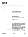
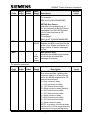
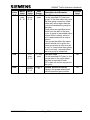
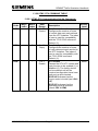
2.6.2 The GSM Modem Unit
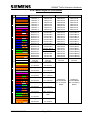
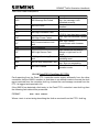
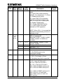
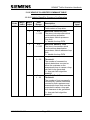
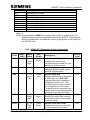
2.6.2.1 SQ864-GPRS Modem Unit
As of late 2011 Gemini units will be fitted with a Sequoia SQ864-GPRS modem
where connection through the GSM network is required. As its name suggest the
modem can also provide a GPRS connection.
The SQ-864 is quad band EGSM 850/900/1800/1900MHz which is compatible with
all GSM mobile networks in the UK. Installation requires an antenna which may be
either the standard cabinet mounted puck antenna (667/1/132600/005) or pole
mounted antenna (667/1/132600/002).
The pole top aerial feeder is a fixed length of 15 metres. Where no signal pole is
available within approximately 8 metres of the controller cabinet, suitable aerial
mounting arrangements will need to be provided. Alternatively the case mounted
antenna may be used.
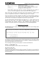
To use the GSM OMCU with the SQ864 modem the RMS Instation must be
equipped with a suitable PTSN modem. Operation of the SQ864 has been verified
with the Hayes Accura V.92 model 08-15328 and Dynalink PK5-5600 modems. It is
known not to operate with the Dynalink PK6. No others have been tried to date.
The user is responsible for setting up airtime agreements with their chosen network
supplier, ensuring that there is adequate signal coverage at the site and obtaining
the appropriate SIM card, which must be: 3V type
Phase 2
Data only
PIN disabled
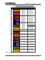
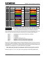
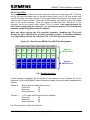
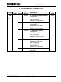
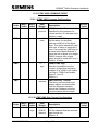
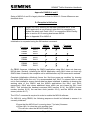
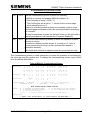
There are three LEDs on the SQ864 indicating modem status as follows:LED colour
Red (STAT_LED)
State
Flash rate once per second: Net search /
not registered / turning off
Slow rate once every 3 s: Registered full
service
Constant ON: Ringing OR call in
progress
OFF: Module power down
Green (TGPIO_01)
Reserved / test only
Blue (TGPIO_02)
Reserved / test only
See drawing 667/CF/26598/020 in Appendix B for installation and set-up instructions.
667/HB/32600/000
Page 26
Issue 11
GEMINI2 Traffic Outstation Handbook
GPRS Connection
The modem may also be used to provide a GPRS connection where Gemini is used
for carpark and VMS applications. In order to work with GPRS some service specific
information must be entered into the Gemini by way of handset commands (this is
normally done by way of a script file).
First enter the GPRS attachment and context AT commands into the Gemini MOS
command:mos=at+cgatt=1;+cgdcont=1,ip,APN
Where APN is the mobile service provider access point name eg. mobile.o2.co.uk for
O2. Note the format of this command string is different from that which would
previously have been entered for the MC35i. Next program the service username
and password:gup=username:password
Finally the ppp authentication mode i.e. PAP/CHAP PAP=1 CHAP=2 eg:ppa=1
Completion of this input should allow the Gemini to connect to the mobile service
provider over the GPRS service.
2.6.2.2 TC35 Modem Unit
This modem is a dual band GSM900/1800 unit but limitations of the aerial restrict its
use in this application to the GSM900 network (Vodafone or Cellnet). In older units it
will be a Siemens TC35 unit, more recent outstations will have been fitted with the
TC35i.
To use the GSM OMCU, the Instation must be equipped with the PACE PCM33.6 or
the Dynalink PK5-5600 Modem. See section 8.4.4 for compatibility details. Note that
new or additional Instation modems may be required to support the GSM OMCU
alongside other 5U and 3U units.
The user is responsible for setting up airtime agreements with their chosen network
supplier, ensuring that there is adequate signal coverage at the site and obtaining
the appropriate SIM card, which must be as follows:
SIM Card
3V type
Phase 2
Data only
PIN Disabled
667/HB/32600/000
Page 27
Issue 11
GEMINI2 Traffic Outstation Handbook
If a GSM OMCU is used, an aerial must be fitted close to the Controller. The aerial
feeder is a fixed length of 15 metres. Where no signal pole is available within
approximately 8 metres of the controller cabinet, suitable aerial mounting
arrangements will need to be provided. There is also a top level Outstation variant
which provides for a case mounted antenna (667/1/32600/005).
There is one LED on the TC35 GSM unit. When the TC35 is powered the LED will
flash; the LED comes on permanently once a GSM service is recognised.
See drawing 667/CF/26598/020 in Appendix B for installation and set-up instructions.
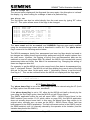
Note: The issue of the TC35 firmware must be 4.0 or above. To determine the issue
of the firmware connect the 9-pin port on the TC35 to a PC serial port running a
terminal emulator. Set the PC to 2400 bits per second, 8 bits no parity, 1 stop bit.
Press the return key several times and then enter ati<return>.
The TC35 should reply with:
Siemens
TC35
Revision 4.0
OK
Where a TC35i modem is fitted the firmware version should be 3.01 or above.
2.6.3 The PAKNET Modem Unit
This is an OEM unit for PAKNET communications via radio.
a)
b)
c)
d)
Auto transmit and receive
4,800 bit/s
Powered from the modem dc supply on the GEMINI2 processor board
On line status indicators
Due to its size, it is not possible to mount this modem onto the back of the GEMINI2
power supply unit. During installation of the Outstation a suitable place should be
found within the associated cabinet.
2.6.4 The DSL Modem Unit
This is an OEM unit for DSL communications over a single pair of copper wires.
a)
b)
c)
d)
Data speeds from 272 Kb/s to 2320 Kb/s
Ethernet Interface – RJ45 Connection
Line Interface – RJ45 Connection
On line status indicators
667/HB/32600/000
Page 28
Issue 11
GEMINI2 Traffic Outstation Handbook
Due to its size, it is not possible to mount this modem onto the back of the GEMINI2
power supply unit. During installation of the Outstation a suitable place should be
found within the associated cabinet.
667/HB/32600/000
Page 29
Issue 11
GEMINI2 Traffic Outstation Handbook
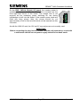
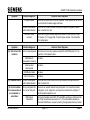
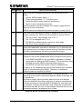
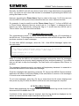
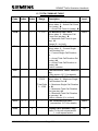
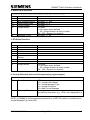
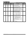
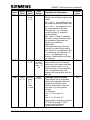
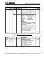
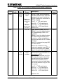
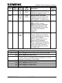
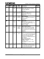
2.6.5 The MC35 GPRS Modem
The Siemens MC35 Terminal unit is a GSM modem capable of GPRS transmission.
The MC35 supports GPRS transmission up to 21.4Kbps per time slot.
Interfaces to the unit include an RS232 data port, power and an FME (male) aerial
connector. An integrated SIM card reader is included. A diagnostic LED shows the
current state of the unit.
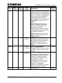
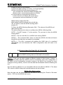
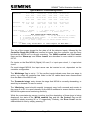
The MC35 Diagnostic LED is used to indicate the following states.
Operating state
Immediately after power up
Network search
or No SIM card inserted
or No PIN entered
or No GPRS network available
Standby GPRS Network
Data Transfer
LED
On for 2 seconds
Flashes approx 2 secs on, 2 secs off
Flashes twice quickly every 4 secs
approx
Flashes on for approx 1 sec when
data is transferred. (This flash usually
replaces the two quick flashes for the
Standby state above)
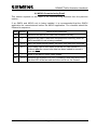
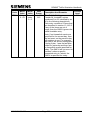
2.7 THE POWER SUPPLY UNIT (PSU)
This is a 127mm long, 76.2mm wide and 37mm high OEM unit, which supplies the
system with +13.65V. The Outstation uses a float charged battery held within the
PSU case to provide total system backup in the event of mains’ failure.
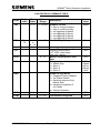
2.7.1 The Power Supply Unit (PSU) Features
(a)
(b)
(c)
(d)
(e)
(f)
(g)
(h)
(i)
Wide range of AC input voltage
3000V isolation from the mains
Can be powered by a 12V to 15V DC input supply. (Future enhancement)
Fitted with a single 12V sealed lead acid battery (see section 7.6.3(a) on page
123)
Automatic switching to the battery support in the event of mains failure to the
system
Automatic recharge on restoration of mains supply to the system
3 years minimum battery life (also see section 7.4 on page 120)
Zero Cross Over – mains supply voltage timing circuit.
2 x High Voltage photo-coupled isolated inputs. Normally used for monitoring
the states of the associated controller’s mains and signal supply voltages.
Note: Graphos has a different PSU. See Graphos Product Handbook
667/HB/31200/000 (Section 4.18 – Graphos Gemini CPU) for the PSU
features.
667/HB/32600/000
Page 30
Issue 11
GEMINI2 Traffic Outstation Handbook
2.8 THE EXPANSION BUS
This is a set of 64 way plugs and sockets. Each board in the system has a connector
fitted that passes through the PCB and becomes a socket on the component side
and a plug on the solder side. The boards connect using these sockets and plugs
through an additional connector, starting with the processor, by plugging an I/O
board into its socket, then an I/O board into the I/O's socket and so on.
All boards provide buffering for Address, Data and Control signals and also distribute
the logic supplies.
2.8.1 The Expansion Bus Features
(a)
(b)
(c)
(d)
(e)
(f)
(g)
24 Address lines
16 Data Lines
15 Control Lines
+5V supply
13.65V Supply (Battery supported when optional battery fitted)
Mechanical fixing at 25.4mm spacing
"Plug able" (to allow expansion)
667/HB/32600/000
Page 31
Issue 11
GEMINI2 Traffic Outstation Handbook
3. SPECIFICATIONS
3.1 INTRODUCTION
The following sections describe the full Electrical, Mechanical, Environmental,
Isolated Outputs, Isolated Extra Low Voltage Inputs, Isolated Low Voltage Inputs,
Analogue Inputs and Communications specifications of the unit.
3.2 ELECTRICAL
For Graphos see the Graphos Product Handbook 667/HB/31200/000 (Section 2.1 –
Electrical Specification) for the Electrical information.
3.2.1 Mains Supply
Normally the unit is powered from an auxiliary mains supply provided within the
controller. In controllers without this facility or if this is not convenient, a suitable
alternative mains supply must be provided, being careful not to compromise the
safety of the controller (Refer to Engineering if in doubt).
Voltage: 230V AC RMS, +15% to -20%
Frequency: 46 - 54 Hz
Mains fused: The recommended rating of this external fuse is 2A anti-surge.
(The mains cable is rated to 6A, fuses up to 5A may be used)
3.2.2 Power Supply
The unit incorporates its own internal power supply unit that provides the necessary
supply voltages to all of the boards and assemblies associated with the complete
unit. The boards are designed and implemented to operate from a single voltage
regulated supply.
Output Supply: Regulated 13.65V DC
Rating: 3.15A
Powering: Processor board, I/O board(s), Modem and Charging the Battery
667/HB/32600/000
Page 32
Issue 11
GEMINI2 Traffic Outstation Handbook
3.2.3 Power Dissipation
Low power CMOS devices are used throughout the unit to keep the power
dissipation as low as possible.
Total power consumption
8.0 W typical (using maximum configuration of 3 x I/O
boards and battery float charging)
3.2.4 Support Batteries
The Outstation unit is fitted with a rechargeable battery which supports the entire
unit, including the modem, for a minimum of four minutes under all conditions in
order that the Outstation may inform the Instation of a mains power failure. This
battery must not be operated in the inverted position (i.e. with the terminals pointing
downwards). See section 5.4.1 on page 77.
A Lithium coin cell battery is provided on the CPU and supports the RAM memory
and the Real Time Clock during power failures for in excess of 7 months. This
battery is plug-able to allow easy replacement.
The processor board also has a ‘Gold Cap’ capacitor fitted that allows the RAM
battery to be changed without loss of RAM data. The Gold Cap device provides a
minimum of 30 minutes support.
The two batteries have the following specifications:
Battery
Type
Support
Unit Battery
12V Lead Acid
20 minutes (Typical)
RAM Battery
Lithium
418/4/53433/000
In excess of 7 months after the
main support battery has expired.
3.3 MECHANICAL
The construction of the unit is based on the standard 3U high, IEC297 Eurocard rack
system. The unit does not use the conventional back plane approach. Instead it uses
an expansion bus (see section 2.8 on page 31), to interconnect the boards
electrically. It does not require the rack to have guide rails, but if present they need
to be on 25.8mm spacing. Mechanically the boards are held in a stack, by four sets
of pillars and fixings, and held in place on a mounting plate. The mounting plate also
accommodates the Modem and PSU assemblies, and is used to fix the total unit
assemblies to the 3U rack, or cabinet mounting side angle bracket.
667/HB/32600/000
Page 33
Issue 11
GEMINI2 Traffic Outstation Handbook
See the Graphos Product Handbook 667/HB/31200/000 (Section 4 – System
Elements) for Graphos mechanical information.
3.4 ENVIRONMENTAL
Temperature
-15°C to +60°C ambient
Humidity
20% to 95% non condensing at 40°C
3.5 ISOLATED OUTPUTS
GEMINI2 Traffic Outstation boards are each equipped with a number of relay isolated
outputs, two change-over contacts on the CPU board, four normally open contacts
on an LMU I/O board and 16 change-over contacts on a BUS / MOVA I/O board. The
following describes the electrical characteristics of these outputs:
CPU Board Output
On Output
Impedance
Off Output
Impedance
182
1%, 0.1
Watts
100k
LMU I/O Board
Output
MOVA I/O Board
Output
182
182
min.
1%, 0.5
Watts *
100k
min.
1%, 0.1
Watts †
100k
min.
Continuous
Current Sink
50mA ‡
50mA ‡
50mA ‡
Breakdown
Voltage
1500V
1500V
1500V
Isolated Voltage
1500V
1500V
1500V
Relay Type
Change-Over
Normally Open
Change-Over
Notes:
*
†
‡
Only the last three outputs on each LMU I/O board have the series resistor
fitted. On old installations the first output is used to control the modem power
(on the first board only) and so has no series resistor.
The last two isolated relay outputs (circuits 15 & 16) have a switch that
enables the resister value to be selected as either 182 or 22 (this allows
for different applications).
The continuous current sink is limited by the resistors.
667/HB/32600/000
Page 34
Issue 11
GEMINI2 Traffic Outstation Handbook
3.6 DIGITAL INPUTS
The CPU board supports 8 x TR2210 (TR0141) compliant digital inputs. Each LMU
I/O board supports 16 x fully software configurable photo-coupled extra low voltage
isolated digital inputs and each BUS / MOVA I/O board supports 48 x TR2210
(TR0141) compliant digital inputs. These digital inputs have the following input
electrical characteristics:
CPU Board
Inputs
Input Impedance
4300 *
LMU I/O
Board 5V
Working
4700
LMU I/O
Board 24V
Working
MOVA I/O
Board Inputs
>12000
4300 *
‘Off’ Threshold
> 50k
< 1V
< 12V
> 50k
‘On’ Threshold
< 600
> 3V
> 18V
< 600
25.6V
39.4V
n/a
49.4V
49.4V
2500V RMS
+1kV / -7V
n/a
Recommended Max.
n/a
Voltage
Absolute Max. Voltage +1kV / -7V
Isolation Voltage 2500V RMS
* Referenced to 13.8V
Each of the LMU I/O board inputs employs an opto-Isolator, with additional circuitry
to protect against reverse voltages and a degree of current limiting. The inputs are
polarity sensitive and one polarity sense give 5V working whilst the other gives 24V
working. (Also see 5.6.2.4 Digital Monitor Connections (LMU I/O Board Only))
3.7 ISOLATED MAINS VOLTAGE INPUTS
The processor board and the associated PSU PCB provide two photo-coupled mains
voltage inputs. Each LMU I/O board also supports 10 x fully software configurable
photo-coupled mains voltage inputs* and a fully configured OMCU provides 30 such
inputs. The function of these inputs is to provide an isolated means of detection of
the presence or absence, of the mains’ signal at the phase drive output terminal
blocks. The following describes the electrical characteristics of a single input.
Each of the inputs again uses an opto-isolator, with additional circuitry, to protect
against reverse voltages, to allow a wide range of mains inputs (including 50 – 0 –
50V AC working for Welsh Office application), also provides current and voltage
limiting.
* Not applicable to the 3RD Party ELV AC LMU I/O Board. See section 3.8.
667/HB/32600/000
Page 35
Issue 11
GEMINI2 Traffic Outstation Handbook
The High Voltage inputs have the following input electrical characteristic:
Input Impedance: 99k
Absolute Max. Applied Voltage: 580V RMS
Min. Voltage to guarantee signal on condition: 40V RMS
Isolation Voltage : 2500V RMS
Note: Graphos has no ZXO signal, therefore mains monitoring is not performed.
3.8 3RD PARTY ELV AC INPUTS
The 3RD Party ELV AC LMU I/O Board supports 10 photo-coupled 48Vrms AC inputs
rather than mains voltages. The function of these inputs is to provide an isolated
means of detection of the presence or absence of the 3RD Party ELV AC signal at the
phase drive output terminal blocks.
The 3RD Party ELV AC LMU I/O Board DOES NOT accept mains voltages of any
kind. The 10 ‘High Voltage’ inputs on this version of the I/O board will accept a
maximum of 50Vrms AC and are clearly labelled as such. The following input
electrical characteristics apply:
Input Impedance: 16.8k
Absolute Max. Applied Voltage: 50V RMS
Min. Voltage to guarantee signal on condition: 15.5V RMS
Isolation Voltage : 2500V RMS
3.9 ANALOGUE INPUTS
Each LMU I/O board supports 10 fully software configurable analogue inputs. The
function of these, when connected to appropriate current sensing toroidal
transformers, is to measure the current supply to the lamps, or when connected to
the appropriate voltage monitor transformer, measures the true level of the lamp
supply voltage (dim or bright). The following describes the electrical characteristics of
a single input.
Each of the inputs is multiplexed to an analogue to digital converter. The analogue
inputs are designed to work with both the current sensing transformer that will
measure currents from 0A to 6A peak (and will accept short term current flows of
12A) and the Voltage monitor transformers, which will measure voltages from 0 to
276V.
Current sensing:
Voltage monitor:
667/HB/32600/000
6A peak
9V peak to peak @ nominal mains
Page 36
Issue 11
GEMINI2 Traffic Outstation Handbook
3.10 COMMUNICATIONS
The processor board contains three serial RS232 and one Ethernet communication
port. The variant /000 of the Bus / MOVA I/O board contains four RS485
communications interfaces which are described on the following page. These
interfaces are fully software programmable in terms of their transmission
characteristic.
The three RS232 and the single Ethernet communications interfaces are shown on
667/GA/32600/000 in Appendix B and are as follows:
3.10.1 Communications Channel 1 TR2210 (TR0141) Port
Location: On back edge of Processor Board
(see 667/GA/32600/000 in Appendix B)
Connector Type: 25 Way ‘D’ Type on the end of a flying ribbon cable
connected to Plug PL4.
3.10.2 Communications Channel 2 (Modem Port)
Location: Towards the back edge of Processor Board
(see 667/GA/32600/000 in Appendix B)
Connector Type: 25 Way ‘D’ Type on the end of a flying ribbon cable
connected to Plug PL2
3.10.3 Communications Channel 3 (Handset)
Location: On front edge of Processor Board
(see 667/GA/32600/000 in Appendix B)
Connector Type: 25 Way ‘D’ Type mounted on board. See Section 3.10.6
for details.
3.10.4 Communications Channel 4 (Ethernet)
Location : On the back edge of CPU Board
(see 667/GA/32600/000 in Appendix B)
Connector Type: RJ45 Socket.
3.10.5 RS485 Communications Interfaces
In addition to the four RS232 communication interfaces, the Bus / MOVA I/O Board
(variant /000) includes four serial RS485 communication interfaces located on the 14
way IDC board connector mounted on the front of the board.
667/HB/32600/000
Page 37
Issue 11
GEMINI2 Traffic Outstation Handbook
Interface : RS485
Isolation : 1000V
Link Type: Master on Multi-drop line
Master Bias: 560
Bias Resistors
Line Termination: Two 120
667/HB/32600/000
Terminating Resistors (selected by switches)
Page 38
Issue 11
GEMINI2 Traffic Outstation Handbook
3.10.6 RS232 Handset Interface
Type
RS232C CCITT V24 and V28
Method of Connection
Traffic Outstation – Cannon DP 25-way socket connector
Terminal Device – Cannon DP 25-way plug connector
Pin Allocation
Pin 1 – Protective ground
Pin 2 – Transmit data from terminal to controller
Pin 3 – Received data from controller to terminal
Pin 4 – Request to send
Pin 5 – Clear to send
Pin 6 – Data set ready
Pin 7 – Signal ground
Pin 9 – 5V supply (see below)
Pin 10 – 5V supply (see below)
Pin 18 – 5V supply return
Pin 19 – 5V supply return
Pin 20 – Data terminal ready
Pins 9 and 10 are connected to the Outstation’s 5V logic supply and can supply a
maximum of 250mA in total.
Bit Format
START BIT
(SINGLE BIT)
1 2
3
4
5
6 7
PARITY
STOP BIT
(LSB •
•
•
•
• MSB)
(EVEN)
(SINGLE BIT)
Baud Rate
1200, 9600, 19200 and 57,600 Baud – Auto-detect
Mode
Full duplex
Character set
ISO alphabet No. 5 (ASCII)
667/HB/32600/000
Page 39
Issue 11
GEMINI2 Traffic Outstation Handbook
4. FACILITIES
4.1 INTRODUCTION
2
The Siemens GEMINI Traffic Outstation provides a flexible multi-function hardware
and software platform, with sufficient interfaces to allow sophisticated monitoring and
control tasks to be developed and executed.
Section 4.2 highlights the facilities available on the GEMINI2 Traffic Outstation when
used as a Siemens RMS OMCU, Bus Processor or Car Park Count OMCU.
Section 4.2.9 describes the DUSC facility.
Section 4.2.10 describes the Flow facility.
Section 4.2.11 describes the Occupancy facility.
Section 4.2.12 describes the OMCU Events and Switch Overrides facility.
Section 4.2.13 describes the Vehicle Classification facility.
Section 4.2.14 describes the Graphos facility.
Section 4.3.1 describes the UTMC OTU facility.
Section 4.3.2 describes the UTMC VMS facility.
Section 4.4 describes the facilities available with the GSM OMCU option.
In addition, the GEMINI2 Traffic Outstation may be used as the hardware platform for
the MOVA software developed in association with the Transport Research
Laboratory. See section 9 which starts on page 140.
4.2 OMCU AND BUS PROCESSOR FACILITIES
The following provides an outline of the facilities supported by the Siemens OMCU.
During the configuration process, timing limit, Bus data, DUSC data, Vehicle
Classification data, flow data, occupancy data, OMCU Event data, Switch Override
data, status check data and Graphos data is downloaded to the OMCU, via modem
or Ethernet link, to provide the following facilities:
Signal Lamp monitoring
Detectors and Push Button monitoring
Controller Status Checks
Controller Timing Checks
DUSC Facility
Flow Facility
Occupancy Facility
OMCU Events and Switch Overrides Facility
667/HB/32600/000
Page 40
Issue 11
GEMINI2 Traffic Outstation Handbook
Vehicle Classification Facility
Local bus priority facilities in association with the Siemens SIETAG reader system
or certain TfL London Bus Priority beacons or an RTIG radio link.
Vehicle selective access control, also in association with the Siemens SIETAG
reader system or certain TfL London Bus Priority beacons or an RTIG radio link.
Graphos Facility
Any fault detected is logged and reported to the Instation identifying the type (i.e.
signal lamp or detector, etc.) and location (i.e. Phase A-RED or stage 2 demand,
etc.).
Some reported faults are automatically ‘cleared’ by the OMCU itself; others can only
be ‘cleared’ by manual means at the Instation. The following lists indicate which
reports clear automatically.
In addition to the OMCU Fault Log, an Operations Log is also maintained which
records all activity related to Vehicle Classification, Bus / Access control actions,
Flow statistics and Occupancy statistics. This may be interrogated locally at the
OMCU or uploaded to the Instation for further analysis.
Note: Not all of the following will be applicable to every controller.
4.2.1 Signal Lamp Monitoring
Under this category the following is provided:
(a)
(b)
(c)
(d)
(e)
(f)
(g)
(h)
Signal lamp bulb failure (phase and colour) – automatically cleared.
Wait lamp bulb failure – automatically cleared.
Regulatory Sign tube failure – automatically cleared.
Dim/Bright change failure – automatically cleared.
Pedestrian Flash Failure – automatically cleared.
Switch Sign bulb failure – automatically cleared.
Signal Lamps on or off – automatically cleared.
Signal lamps flashing or not flashing – automatically cleared. (Applicable to
export sequences only.)
4.2.2 Detector and Push-Button Monitoring
Under this category the following is provided:
(a)
(b)
(c)
(d)
(e)
Detector Fault – both stuck active and inactive
Push Button fault – both stuck active and inactive
Dual or Single Fault Timer monitoring – on any selected digital input
Detector Transition Counting
Detector Counting – N and N + 1 algorithms
667/HB/32600/000
Page 41
Issue 11
GEMINI2 Traffic Outstation Handbook
4.2.3 Controller Status Checks
Under this category the following is provided:
(a)
(b)
(c)
(d)
(e)
(f)
(g)
(h)
(i)
Controller mode, i.e. Manual, Fixed-Time, V.A
Controller Stuck – applicable to Fixed-Time mode only
Controller ignoring demands – including call/cancel and filter demands
Controller mains supply re-applied.
Conflicting Phase Greens
Stage sequencing fault
External signal active, e.g. cabinet door open
TR2210 (TR0141) controller fault log
Controller/OMCU Handset Terminal connected
4.2.4 Controller Timing Checks
(These checks are not normally required on a TR2210 [TR0141] controller)
Under this category the following is provided:
(a)
(b)
(c)
(d)
(e)
(f)
(g)
(h)
(i)
Short Stage Minimum
Short and Long Stage Extensions
Long Stage Maximum
Long Alternative Stage Maximum
Short Phase Inter-green
Long Inter-Stage
Long All-Red
Variable Maximum Timing Log
SDE/SA Extension Request Log
4.2.5 Bus Processor Functions
When used for Bus Processor applications, the unit can be connected to up to 12
SIETAG readers, City of London (TfL) bus priority beacons or a single RTIG radio
sub-system (see section 5.6.4 for wiring) to provide logging, priority and access
control functions.
Vehicles to be given access / priority via SIETAG are fitted with an electronic tag that
may be programmed with, amongst other things, vehicle operator identification and
individual vehicle number. A loop is located in each access lane, which is used by a
reader to interrogate tags as they pass over.
Vehicles to be given access / priority via beacons and RTIG are generally fitted with
intelligent in-vehicle systems capable of providing a level of real-time information
based on current position and adherence to a known timetable.
Data from the vehicles is filtered by the Bus Processor which will log the information.
The Bus Processor can be programmed to output access requests to barriers or
667/HB/32600/000
Page 42
Issue 11
GEMINI2 Traffic Outstation Handbook
other equipment such as Traffic Controllers, via up to 16 isolated relay contacts
(expandable to 48 with additional I/O boards).
Several levels of filtering may be configured in each Bus Processor. Filtering options
range from specific access for uniquely identified vehicles to all vehicles of a
particular operator. Access may be restricted by time of day and individual or groups
of vehicles may be blacklisted.
4.2.5.1 Routing SIETAG Vehicle Detections to an OTU
An overview of the SIETAG OMCU – OTU facility is shown in the following figure.
FOR
CONFIGURATION
& DIAGNOSTICS
VEHICLE TAG
LOCAL
HANDSET
TAG DETECTOR
LOOP(S)
TC12
PROTOCOL TO
UTC CENTRAL
OFFICE
RS232
READER
RS232 to OTU
HANDSET
PORT for UTC
LOG
RS485
TC12 OTU
OMCU
READER
OUTPUT BITS DIRECT
FROM READER OR
OMCU FOR SCOOT
BUS PRIORITY
READER
UTC
CONTROL &
REPLY BITS
TRAFFIC
CONTROLLER
RADIO CLOCK
ETC
Figure 9 – SIETAG OMCU to OTU
The Bus processor may be locally configured via the handset (LDV=4) to route
SIETAG vehicle detections through the 141 serial port to an OTU as a sequence of
13 GED environmental sensor commands. Each set of 13 commands comprises of
the original 8 bytes of the vehicle detection, prefixed by a time stamp and the
identification of the SIETAG reader that supplied the detection. The SIETAG reader
identification must be configured by the user via the handset (using the BID handset
command – see section 13.10), otherwise a default of 0 is returned for each vehicle
detection, irrespective of the SIETAG reader that supplied the vehicle detection.
NOTE: The Loop number supplied with vehicle detections from V3.3 or
later SIETAG readers is not supplied to the OTU.
The data byte accompanying each command is decoded by the OTU and relayed as
16 reply bits to a UTC Instation where the information can be used for applications
such as travel times analysis.
667/HB/32600/000
Page 43
Issue 11
GEMINI2 Traffic Outstation Handbook
This facility uses the standard 141 serial cable 667/1/26579/000 to connect the unit
to the OTU handset port.
Once the OMCU – OTU cable is connected and LDV=4 entered, the XXC command
can be used to gain access to the OTU handset (XXO is used to revert to the OMCU
handset).
The OTU must be appropriately configured to provide the throughput to the UTC
using the following handset commands. Normal OTU configuration parameters, such
as:
Mnemonic
GAD
GMM
GNO
GRW
GOE
Description
OTU Address
Line Characteristics of OTU / UTC Link
Total Number of OTUs on the same OTU / UTC Link
Number of Reply Bytes (2 required for this application)
Enable UTC Reply / Control Byte Interface
Plus the following to configure and enable the environmental sensor interface:
Mnemonic
GRL r b = 57
GEC n = 1
Description
Assign Environmental Sensor Data to Reply Bytes (16 bits),
starting at reply byte ‘r’ bit ‘b’
Enable Environmental Sensor Channel ‘n’ (repeat for n = 1 to
13)
Details on the use of the OTU handset commands can be obtained from the TC12
Installation, Commissioning and Maintenance Handbook 667/HE/43100/000.
NOTE: When this facility is configured, the unit cannot perform controller monitoring
via the 141 serial port.
The following version of firmware is required for the standard Bus Processor
functionality plus the routing of the vehicle detections to an OTU.
4.2.6 ST800/700 Enhanced Link
The ST800/700 enhanced serial link provides a new high data rate link over the
standard 141 cable between the Siemens ST800/700 traffic controller and the
Siemens GEMINI2 Traffic Outstation. This link allows the two units to continuously
communicate with each other in order to provide a more integrated overall traffic
product.
Normally, an Outstation requires lots of wires to be connected to various points in the
traffic controller to allow the OMCU to monitor and control the controller. This new
enhanced link has removed the need for much of the wiring and less wiring not only
simplifies the installation, but also should provide a more reliable product – fewer
wires mean fewer connections that can fail.
667/HB/32600/000
Page 44
Issue 11
GEMINI2 Traffic Outstation Handbook
As a more integrated product, the traffic controller provides some of the facilities that
previously only the OMCU could provide. The controller performs the lamp
monitoring and detector fault monitoring, passing any fault information to the OMCU
for reporting to the RMS Instation. The controller’s digital inputs and mains states,
etc. are also passed over the serial link allowing the OMCU and MOVA applications
to read them as though they were connected directly to the unit.
For more information on MOVA using the enhanced 141 link, see section 9.6.4 on
page 153.
The OMCU enhanced 141 link is configured on RMS screen 010, by selecting the
Monitoring Type as “Serial” rather than “Full” when the controller type is “800P”. The
ST800/700 traffic controller itself does not need to be configured to enable the
enhanced serial link to the OMCU application.
However, the ST800/700 traffic controller needs to be configured to use ‘Serial
MOVA’ rather than its normal digital I/O UTC interface. Also, the “MIO” handset
command may be required to configure MOVA to use the enhanced 141 link rather
than its I/O board. Again, see section 9.6.4 on page 153 for more information on
MOVA and the enhanced 141 serial link.
The OMCU handset command EEL can be used to examine the state of the
enhanced link (see section 13.8 on page 245).
When the enhanced ST800/700 link is enabled, the OMCU handset commands
operate as described below (any commands not listed operate as before):
Command
Operation (when enhanced link enabled)
LMR, KAC,
KLS, KAS
These commands are inactive – use the corresponding lamp monitor
commands directly on the controller.
KDB
Displays dim/bright state based on the controller lamp supply voltage
received via the serial link.
KLM
Displays the lamps’ on/off state as received from the controller via
the serial link. The OMCU reverts to using the state of its second
mains’ state input, if the controller link fails. If the mains state input is
not connected and the link fails, then ‘lamps off’ is reported.
PGS
Displays the phase green states received from the controller via the
serial link
CPP
Current Phase Pattern, derived from phase green states (the phase
patterns are defined on the configuration data screens for the
OMCU).
667/HB/32600/000
Page 45
Issue 11
GEMINI2 Traffic Outstation Handbook
Command
Operation (when enhanced link enabled)
CST
Displays the current stage for stream 0, received from the controller
via the serial link
MDE
Displays the controller mode for stream 0, received from the
controller via the serial link
MSI
Displays the OMCU mains state inputs (not controller greens)
DIP
Displays the OMCU digital inputs (not controller inputs)
SOB & SOP
Displays/sets the OMCU digital outputs (not controller outputs)
4.2.7 Car Park Count Detection
A mechanism is provided to enable car park occupancy to be determined.
A total of 10 detector loops can be connected to the OMCU. These are configured as
either car park entry or exit loops. The occupancy of the car park is determined by
the difference in the number of vehicles entering and exiting the car park.
Car park counts can also directly from an APT Skidata system instead of from
individual loops.
See section 10 for more details.
The following data is transmitted to the Instation:
Car park Occupancy
Failed Detector Loops (both stuck active and inactive)
Power Fail
Cabinet Door open
Car park state (Full, Almost Full, Empty or Closed)
Loop Counts
4.2.8 PAKNET / GPRS interface
When the OMCU is used to detect car park occupancy, the information is passed to
the SIESpace Instation via either a PAKNET interface or by GPRS, rather than the
PSTN.
PAKNET is Vodafone’s packet data network. This is connected to the Instation via a
‘Radio-Pad’, which is an asynchronous terminal device that replaces the modem on
the OMCU.
GPRS provides radio communications utilising GSM public mobile telephone
networks provided by the likes of O2, Vodafone and Orange. GPRS provides a
TCP/IP based link where data is charged by the amount transferred and not the
duration of the connection.
667/HB/32600/000
Page 46
Issue 11
GEMINI2 Traffic Outstation Handbook
4.2.9 DUSC Facility
The DUSC facility is very similar to CLF used in the ST800/700 traffic controller,
whereby plans are introduced at specific times of day and each plan cycles through
a configured sequence of groups in a repeating cycle. At each configured group time
within the cycle, the OMCU activates the specified outputs to influence the controller
movements (See DUSC user handbook for full details).
Plans are introduced by the timeswitch table i.e. dependent on the time of day, day
of the week and (optionally) on the date. Plans can also be introduced via the
handset or via user defined conditioning. The DUSC facility has the following
features:
(a)
Up to 16 plans, with 32 groups per plan. Up to 32 streams.
(b)
Timeswitch table with up to 64 entries.
(c)
Plan compliance checking and fault reporting.
(d)
Fault report of simultaneous green confirms (G1, G2 active).
(e)
Real time update information includes current plan, current group, forces,
confirms, on/off control and cycle time.
(f)
“Remote Reconnect” (RR) input available on OMCU to disable plan control for
maintenance purposes.
(g)
There are 3 methods of interfacing with an ST800/700…
Control Force and Reply (See section 4.2.9.1 – Force Bit Control
Installation)
141 cable (See section 4.2.9.2 – ST800/700 Enhanced Serial Link Control
Installation)
Detector Control (See section 4.2.9.3 – Detector Control Installation)
667/HB/32600/000
Page 47
Issue 11
GEMINI2 Traffic Outstation Handbook
4.2.9.1 Force Bit Control Installation
SIGNAL
HEADS
LOCAL
HANDSET
RMS
PROTOCOL TO
INSTATION
RS232
GREEN
CONFIRMS
STAGE
CONFIRMS
PSTN or
GSM
OPTION:
GPS Receiver
(clock)
TRAFFIC
CONTROLLER
OMCU
(with LGD Battery
& MODEM)
FORCE
BITS
RS232/
RS485
DETECTOR
LOOPS
Figure 10 – Force Bit Control Set-up
Figure 10 shows how an OMCU can be set up for Force Bit control. This type of setup is used when the controller provides a UK standard UTC style interface. It shows
the ‘Force Bits’ from the OMCU being fed into the traffic controller, via the TR0141
UTC Interface. It also shows the ‘Stage Confirms’ coming back from the traffic
controller to the OMCU. Although the ‘Demand Bits’ and ‘Green Confirms’ are still
being sent to the OMCU for lamp monitoring and DFM, etc, the CLF ignores this
information, as it is getting its information from the stage confirms.
667/HB/32600/000
Page 48
Issue 11
GEMINI2 Traffic Outstation Handbook
4.2.9.2 ST800/700 Enhanced Serial Link Control Installation
SIGNAL
HEADS
LOCAL
HANDSET
RMS
PROTOCOL TO
INSTATION
PSTN or
GSM
OPTION:
GPS Receiver
(clock)
RS232
OMCU
(with LGD Battery
& MODEM)
FORCE
BITS,
CONFIRMS,
ETC
TRAFFIC
CONTROLLER
ST800
ENHANCED
SERIAL
LINK
RS485
DETECTOR
LOOPS
Figure 11 – ST800/700 Enhanced Serial Link Control Set-up
Figure 11 shows how an OMCU can be set up for the ST800/700 Enhanced Serial
Link control. It shows all the information being fed between the OMCU and the traffic
controller, via the ST800/700 Enhanced Serial Link.
667/HB/32600/000
Page 49
Issue 11
GEMINI2 Traffic Outstation Handbook
4.2.9.3 Detector Control Installation
SIGNAL
HEADS
LOCAL
HANDSET
RMS
PROTOCOL TO
INSTATION
PSTN or
GSM
OPTION:
GPS Receiver
(clock)
RS232
GREEN
CONFIRMS
TRAFFIC
CONTROLLER
OMCU
(with LGD Battery
& MODEM)
RS232/
RS485
DEMAND BITS
DETECTOR
LOOPS
Figure 12 – Detector Control Set-up
Figure 12 shows how an OMCU can be set up for Detector control. This set-up is
only used where controllers are not to UK standard with a UTC interface, i.e. it can
be used with any vehicle actuated controller. It shows the ‘Demand Bits’ from the
Detector Loops being fed into the OMCU, which are then sent out from the OMCU to
the traffic controller. It also shows the ‘Green Confirms’ coming back from the traffic
controller to the OMCU.
4.2.10 Flow Facility
The Flow facility has 16 detectors; each provides flow data over a configured period
of time. Configuration data for this facility includes: Flow Up Threshold, Flow Down
Threshold, Flow Smoothing Factor and Flow Count Period.
The Instation will send a Log Flow Request to the OMCU. It will request the OMCU
to start/stop accumulating smoothed flow data after a specified delay. The delay is
computed by the Instation so that the command will be executed by the OMCU at the
time of day specified by the user.
The OMCU will reply to the Log Flow Request with a message indicating that the Log
Flow Request has been received.
667/HB/32600/000
Page 50
Issue 11
GEMINI2 Traffic Outstation Handbook
For each interval completed a report is generated and stored in the Operations Log.
When the final interval has been completed and report generation has been enabled,
a report is written to the Fault Log to indicate that Flow Logging has been completed
and is ready for uploading.
More accurate values of flow data can be obtained at 2 or 3 sites, using the N+1
Count Data. The flow threshold would be for the complete carriageway rather than
individual lanes.
In addition to the collation of the flow data, the flow data can be monitored and
compared to the configured up/down thresholds. If the flow data meets the ‘up’ or
‘down’ threshold, the related OMCU Event can be activated/deactivated and the flow
alarm is raised/cleared.
4.2.11 Occupancy Facility
The Occupancy facility has 16 detectors; each provides occupancy data over a
configured period of time. Configuration data for this facility includes: Occupancy Up
Threshold, Occupancy Down Threshold, Occupancy Smoothing Factor and
Occupancy Count Period.
The Instation will send a Log Occupancy Request to the OMCU. It will request the
OMCU to start/stop accumulating smoothed occupancy data after a specified delay.
The delay is computed by the Instation so that the command will be executed by the
OMCU at the time of day specified by the user.
The OMCU will reply to the Log Occupancy Request with a message indicating that
the Log Occupancy Request has been received.
For each interval completed a report is generated and stored in the Operations Log.
When the final interval has been completed and report generation has been enabled,
a report is written to the Fault Log to indicate that Occupancy Logging has been
completed and is ready for uploading.
In addition to the collation of the occupancy data, the occupancy data can be
monitored and compared to the configured up/down thresholds. If the occupancy
data meets the ‘up’ or ‘down’ threshold, the related OMCU Event can be
activated/deactivated and the occupancy alarm is raised/cleared.
4.2.12 OMCU Events and Switch Override Facility
The maximum number of OMCU Events and Switch Overrides is 16. Each OMCU
Event and Switch Override is independent and more than 1 can be active
simultaneously.
Configuration data for the OMCU Events facility includes Debounce Active Delay and
Debounce Inactive Delay.
667/HB/32600/000
Page 51
Issue 11
GEMINI2 Traffic Outstation Handbook
An OMCU Event has to be continuously active for the configured active debounce
time, before a report is written to the Fault Log, indicating the OMCU Event is active.
Conversely, an OMCU Event has to be continuously inactive for the configured
inactive debounce time, before a similar report is written to the Fault Log, indicating
the OMCU Event is inactive. The Instation then processes these events via a
decision tree and takes the appropriate configured response (Switch Override).
The RMS Instation can request a Switch Override at the OMCU, when the OMCU
Event becomes active. The OMCU will reply to the Switch Override Request with a
message indicating that the Switch Override Request has been received.
When the OMCU starts the Switch Override (start time is reached) and report
generation is enabled, a report will be written to the Fault Log to identify the start of
the Switch Override.
The Switch Override will remain active for a fixed period of time, or until cancelled
from the Instation.
A similar report will be generated at the end of the Switch Override, (end time is
reached, assuming that an indefinite override period has not been specified) if
enabled.
4.2.13 SieClass Vehicle Classifier Facility
The Vehicle Classification facility provides classification of vehicles by length into a
maximum of 14 user specified length categories. Vehicles that exceed the length in
the longest length category are assigned to the “Unassigned” length category.
Vehicles that are not able to be measured (e.g. transit one of the loops only) have
zero length and are assigned to the “Unmeasured” category. Each length category is
configurable to provide user names for the categories, e.g. “Car / Small Van”.
Vehicles may be logged on up to 8 loop pairs distributed across up to 4 sites, each
site containing up to 8 lanes. It is recommended that the facility use standard
SDE/SA loops of typically, 2m loop length and 3.5m loop separation. The ST4R loop
detector is also recommended.
It is important to note that differently sized loop pair configurations must be assigned
to different sites.
The vehicles may be individually logged in the Operations Log when they are
detected as VC events. The VC event identifies the vehicle type, length, speed,
headway and action taken (if any) on detecting the vehicle. Each value may be
optionally configured for inclusion / exclusion from the VC event. VC event logging
may be enabled / disabled for any given lane within a given site via the configuration
download.
The user is able to freely specify up to 32 detection conditions via special
conditioning e.g. vehicles of between 2m and 5.5m in length occurring at a given site
667/HB/32600/000
Page 52
Issue 11
GEMINI2 Traffic Outstation Handbook
travelling in excess of 80kph. Of these 32 detection conditions, up to 16 may be
selected for statistical collection purposes.
NOTE: Non-vehicle classifier special conditioning mnemonics may be used in the
definition of the detection conditions, however they should not be mixed with the
vehicle classifier special conditioning mnemonics.
Vehicle detections may be collected over a user specified averaging period of
between 1 and 60 minutes to be summarised in the Operation Log as TD events by
average speed, average occupancy and average headway. The average speed,
headway and occupancy values may be recorded on a site or a lane basis or be
omitted entirely. The statistic categories increment during the averaging period to
reflect the occurrence of user defined detection conditions. These category counts
are presented in the Operations Log alongside the summary information in the TD
event described above. The statistic categories may be omitted from the TD event.
The data collection is synchronised to the minute boundary. The time stamp
associated with the TD event corresponds to the end of the averaging period.
TD event generation may be enabled / disabled via the configuration download.
When vehicle detection satisfies a detection condition, a DC event may be recorded
in the Operations Log identifying the detection condition. It is possible for a single
vehicle detection to satisfy more than one detection condition (depending on how the
detection conditions have been defined) and hence there may be more than one DC
event associated with single vehicle detection.
The DC, VC and TD events in the Operations Log may be selectively uploaded to the
RMS Instation for analysis.
The occurrence of a user-defined condition may be used to force the activation of
one or more OMU outputs (up to a maximum of 16 allocated across 2 output ports)
to trigger an action in an external device such as a traffic controller. A configurable
text message may also be presented to one or more message signs such as UVMS
or a SIESPACE sign. A sign may be connected to the 141 serial port or one of the
available RS485 serial ports on a 1 to 1 basis. The text message is displayed for a
configurable period and may be subsequently blanked by a blanking message
applicable to the sign or be replaced by a second text message. NOTE: If a second
text message is output to the sign, the message will remain on the sign until another
action causes the same sign to be addressed. Alternatively, the sign configuration
could perform a self-blanking using a suitable inactivity timeout.
Confirmation checks are carried out to detect the absence / presence of an expected
input state arising from an output activation. The absence of an expected input state
for a configured period generates a fault in the Fault Log. The presence of the
expected input state for a configured period clears the fault (if the fault is present).
The RMS Instation operator may manually reset the fault.
NOTE: Confirmation checks are not performed on sending text messages to a sign.
667/HB/32600/000
Page 53
Issue 11
GEMINI2 Traffic Outstation Handbook
Vehicle absence / presence faults are generated in the Fault Log if a vehicle is not
detected over a loop / detected over a loop for longer than the configured absence /
presence time. Both fault types are automatically cleared by the OMU. The RMS
Instation operator may manually reset both fault types.
The Vehicle Classification facility also supports a loop pair fault algorithm. This
algorithm identifies a loop pair as faulty if one of the loops is activated on N
consecutive occasions with no activations on the other loop. The fault is cleared by
the OMU if there are M activations (not necessarily consecutive) of both loops. N and
M are configurable values.
The RMS Instation operator may manually reset the loop pair fault.
There is a set of read only handset commands to allow the user to examine the
Vehicle Classifier configuration data items – see section 13.18.
The Vehicle Classification facility requires the use of an STC supplied licence
code in order to be activated. The licence code is based on the OMU telephone
number and is downloaded as part of the Vehicle Classification configuration
data from an RMS Instation. See section 6.3, step 23 on page 115.
4.2.14 Graphos Facility
The Graphos facility provides communication to a range of variable message signs.
The signs are characterised into three types:
● Speed warning signs. These signs are activated by speed measuring
detectors. The detectors can be loop or microwave based. The signs are blank for a
great proportion of the time but illuminate when vehicles are detected travelling in
excess of the speed limit and display the speed limit to remind drivers of the speed
limit in force.
● General purpose warning signs. These are used to warn motorists of potential
hazards such as sharp bends ahead. They are similar in function to Speed Warning
signs but are usually larger and use symbols mostly within the red warning triangle.
They usually are activated by vehicles travelling over a speed threshold but other
activation methods are possible. Alternative activation methods are axel
measurement via loops for weight restrictions or high detection for low bridges, etc.
● Variable speed limit signs. These signs are used to set the speed limits and
allow them to be changed, usually at certain times of the day. Typical applications
are for use around school entrances, to reduce the speed limit, for example to 20
mph, at times of the day when school entrances are active. These signs usually do
not have any form of detection present as the variable speed limit is activated by a
time table held within or communicated to the sign.
667/HB/32600/000
Page 54
Issue 11
GEMINI2 Traffic Outstation Handbook
The Graphos facility can generate and report the following failures to RMS:
(a)
(b)
(c)
(d)
(e)
(f)
(g)
(h)
(i)
(j)
(k)
Communication Fault/Power Fail – automatically cleared.
Invalid set message – manually cleared.
Receiving data from unconfigured signs – manually cleared.
Radar has not triggered – manually cleared.
Voltage on LDB board is missing – manually cleared.
LED driver board system fault – manually cleared.
Invalid picture number in last Set – manually cleared.
Ambient Light Sensor failure – manually cleared.
LED Failure Detected – automatically cleared.
Incorrect Picture being Displayed – manually cleared.
LDB board is missing or defect– manually cleared.
Figure 13 gives the Graphos Block diagram.
667/HB/32600/000
Page 55
Issue 11
GEMINI2 Traffic Outstation Handbook
Graphos
Rx/Tx
N
Either wire or radio
engineering RS232
is fitted but not both
5
Optional
5
5
9
18
SK2
SMA
2
PL3
P
Gemini CPU
PL5
PL4
9
PL2
667/1/26608/001
Modem
PSTN or GPRS
Q
2
R
RJ11
PL7
6
AGD 200 ‘Live
Wire’ Vehicle
Over-Speed
Detector
M
2
C
5
A
Battery Control
Circuitry
Toroidal
Transformer
1:10
2
Battery
M
418/4/42314/010
2
BT Cable
M
PSU
13.8 V d.c. 40W
24
way
Term.
Block
9
BT Line (6 way cable)
5
D
2
F
18
B
4
H
Spare (2 way)
Graphos
Comms
20 way Cable
PSU
48 V d.c. 70W
G
2
2
2
S
2
24 v a.c. (2 way)
X9
X9
Engineering RS232 (5 way)
SD4 Detector inputs (9 way)
3
E
X1
X10
30
J
X1
Mains Flex
LSCU Control Board
Mains 230 V a.c. (3 way cable)
Line 1
N
Earth
6
way
Term.
Block
Mains
Filter
6
way
Term.
Block
S24777-A3340-A25
X12
X2
X9
30
L
X3
X4
16
X5
16
X6
16
X10
X1
1
X12
LED Driver
Board #2
X1
S24777-A3380-A21
16
2
X1
1
LED Driver
Board #1
X4
Slave RS485 (2 way)
Neutral
X10
X2
X2
S24777-A3380-A21
X3
X4
X5
16
16
16
X6
16
X6
Configuration key
32 LED Strings
32 LED Strings
Figure 13 – Graphos block diagram
667/HB/32600/000
Page 56
Issue 11
GEMINI2 Traffic Outstation Handbook
4.2.15 RMS Firmware Download Facility
The Siemens GEMINI2 Traffic Outstation supports the remote download of firmware
from an RMS Instation over a PSTN link. The Outstation configures its modem for
19200,8,N,1 operation.
This facility is not supported when an RMS Instation is connected to the local handset.
The download of firmware is initiated by the RMS operator. When the download has
completed the Outstation switches to using the downloaded firmware when instructed to
do so by the RMS Instation. If required by the RMS operator, the Operations Log may
be uploaded to the RMS Instation, before the switch takes place.
The Outstation performs a reboot and initialisation in order to switch to the downloaded
firmware. During the switch over, the new firmware will attempt to execute with the
configuration data that the previous version of firmware used. If the new firmware
requires configuration data items not contained within the recovered configuration data,
the unit must be reloaded with a new configuration.
The RMS operator is informed of firmware download completion, switch firmware
request and switch firmware completion only when the unit has been configured.
If the version number of the download firmware is lower than that of the executing
firmware OR the part numbers differ and the version numbers match, then it will not be
possible to revert back to the executing firmware once the switch has occurred.
For example
Downloaded firmware 12686 Issue 2, executing firmware 12686 Issue 3
Downloaded firmware 12686 Issue 2, executing firmware 12687 Issue 2
In both the above scenarios, the Outstation will contain only firmware 12686 Issue 2
after the switch.
If the version number of the download firmware is higher than that of the executing
firmware, then it will be possible to revert back to the executing firmware once the
switch has occurred.
For example
Downloaded firmware 12686 Issue 3, executing firmware 12686 Issue 2
In this scenario the Outstation will contain both firmwares after the switch.
The Outstation continues to operate normally during the download of firmware.
667/HB/32600/000
Page 57
Issue 11
GEMINI2 Traffic Outstation Handbook
4.3 UTMC FACILITIES
4.3.1 UTMC OTU Facility
2
The Siemens GEMINI Traffic Outstation can also be configured to provide the Traffic
Controller Outstation facility for a UTMC system.
In this mode the outstation is configured either as shown in Figure 14 or as shown in
Figure 15. In both cases the OTU must be connected to a suitable network modem,
usually via the CPU card Ethernet interface.
SIGNAL
HEADS
LOCAL
HANDSET
RS232
STAGE
CONFIRMS
TRAFFIC
CONTROLLER
Ethernet
UTMC OTU
DSL
MODEM
SCOOT
INPUTS
FORCE
BITS
UTMC
PROTOCOL TO
INSTATION
SCOOT DETECTOR
LOOPS
VA DETECTOR
LOOPS
Figure 14 – Freestanding UTMC OTU Set-up
Figure 14 shows how a Freestanding UTMC OTU can be set up for Force Bit control.
This type of set-up is used when the controller provides a UK standard UTC style
interface. It shows the ‘Force Bits’ from the OTU being fed into the traffic controller, via
the TR2210 (TR0141) UTC Interface. It also shows the ‘Stage Confirms’ coming back
from the traffic controller to the OTU. For SCOOT applications inputs from specially
positioned ‘flow’ detectors can also be interfaced to the unit.
667/HB/32600/000
Page 58
Issue 11
GEMINI2 Traffic Outstation Handbook
SIGNAL
HEADS
LOCAL
HANDSET
RS232
EHANCED
SERIAL
LINK
Ethernet
ST700/800
TRAFFIC
CONTROLLER
UTMC OTU
DSL
MODEM
SCOOT
INPUTS
UTMC
PROTOCOL TO
INSTATION
SCOOT DETECTOR
LOOPS
VA DETECTOR
LOOPS
Figure 15 – ST800/700 Semi-Integral UTMC OTU Set-up
Figure 15 shows how an OTU can be set up for the ST800/700 Enhanced Serial Link
control. It shows all the information being fed between the OTU and the traffic
controller, via the ST800/700 Enhanced Serial Link. No I/O cards are required in this
configuration.
Separate inputs on the CPU card are provided to permit connections for up to 8
associated SCOOT detectors. This requires cableform part number 667/1/30607/000.
The UTMC OTU facility requires the use of an STC supplied licence code in order
to be activated. The licence code is based on the Processor PCB being used. See
section 6.3, step 23 on page 115.
4.3.2 UTMC VMS Facility
The Outstation can be configured to provide an interface between a SIESpace Instation
and up to 8 UVMS signs via an IP based network using the UTMC VMS system.
The following diagram (Figure 16) shows an example configuration of the UTMC VMS
System:
667/HB/32600/000
Page 59
Issue 11
GEMINI2 Traffic Outstation Handbook
RS485 Bus
Channel 0
Sign 0
Sign 1
CH #0
Ethernet
DSL Modem or
other Ethernet
Converter
Local
Handset
Gemini Traffic
Outstation
CH #1
RS232
Sign 2
CPU Card
Bus Mova Expansion I/O
Card
PSU & Chassis
Sign 3
RS485 Bus
Channel 1
Figure 16 – UTMC VMS System Overview
When the Outstation is configured in UTMC VMS mode, UTMC VMS messages from
the SIESpace Instation arrive via the Ethernet connection. The Outstation converts
these messages into the SIESpace protocol and transmits them to the required sign via
the RS485 Bus. The Outstation also collects status information from the VMS signs and
this information can be integrated remotely via the UTMC VMS protocol over the
Ethernet link.
The UTMC VMS facility requires the use of an STC supplied licence code in order
to be activated. The licence code is based on the Processor PCB being used. See
section 6.3, step 23 on page 115.
4.4 GSM OMCU
The GSM OMCU is an extension to the Siemens RMS OMCU described in section 4.2.
It provides an extremely cost effective means to monitor and control equipment where
standard PSTN connection is not available or where the line installation costs are
prohibitive.
See Sections 2.1 and 2.6.2 for further details of the GSM option.
4.4.1 Remote Monitoring
The GSM version provides all the facilities of a standard 3U OMCU and is capable of
monitoring a wide variety of traffic signal and pedestrian controllers. The unit is
configured from a RMS via a dial-up link to perform the monitoring and control functions
required.
667/HB/32600/000
Page 60
Issue 11
GEMINI2 Traffic Outstation Handbook
When a fault or other defined event is detected, it is logged at the unit and a call is
made to the Instation to report the occurrence. If required, particular types of fault or
event can be configured as “non urgent” so that these are logged but not reported to the
Instation, unless a more urgent fault is detected or a call is made from the Instation.
Integral n+1 count units allow simple detector equipment to be used to monitor traffic
flows, which are reported to the Instation automatically or on operator request.
Direct connection to a wide range of traffic controllers via their handset port allows an
operator at the Instation to interrogate the controller remotely and make changes to the
controller operation.
Variable Message Signs and access control equipment such as barriers may also be
controlled.
4.4.2 Bus Priority and Access Control
When used for Bus Priority and access control applications, the GSM OMCU is able to
connect up to 12 SIETAG readers using a suitable I/O board to provide logging, priority
and access control functions.
Vehicles to be given access / priority are fitted with an electronic tag that may be
programmed with, among other things, vehicle operator identification and individual
vehicle number. A loop is located in each access lane, which is used by a SIETAG
reader to interrogate tags as they pass over.
Data from the tags may be filtered by the GSM OMCU, which logs the information and
can be programmed to output access requests to barriers or other equipment such as
Traffic Controllers, via up to 16 isolated relay contacts. (These may be expanded up to
48 by the addition of extra I/O boards.)
Several levels of filtering may be configured from the Instation and downloaded to the
GSM OMCU. Filtering options range from specific access or priority just for uniquely
identified vehicles through to all vehicles of a particular operator. Access / priority may
be restricted by time of day and individual or groups of vehicles may be blacklisted.
Bus Processor and OMCU functions can be performed simultaneously, limited only by
the number of I/O boards that can be accommodated.
4.5 Ethernet OMCU
The OMCU may also be connected to the RMS instation via an Ethernet connection.
Once an IP address has been assigned to the OMCU it can then be configured to
operate as a Gemini OMCU with communication to the RMS instation across a network.
Initially the IP address must be setup manually using the IPM handset command to
setup a static IP address and then IPR=2 to activate the IPM settings. This will most
probably be done locally via the handset port, though it could be done remotely if a
modem is fitted. Once the IP address has been assigned configuration data that
667/HB/32600/000
Page 61
Issue 11
GEMINI2 Traffic Outstation Handbook
designates the OMCU as an IP outstation can be downloaded from the instation and
from that point the OMCU will operate as normal but via an Ethernet link.
667/HB/32600/000
Page 62
Issue 11
GEMINI2 Traffic Outstation Handbook
5. INSTALLATION
WARNING
THIS EQUIPMENT MAY ONLY BE INSTALLED IN A RESTRICTED ACCESS
LOCATION BY SIEMENS TRAFFIC CONTROLS OR BY TRAINED PERSONNEL.
AUTHORISED INSTALLER MUST ENSURE THAT INSTALLATION OF THIS
EQUIPMENT DOES NOT INTERFERE OR DEGRADE THE DESIGN SPECIFICATION
OF THE HOST EQUIPMENT IN ANY WAY WHATSOEVER.
ENSURE THAT THE UNIT IS NOT CONNECTED TO THE PSTN LINE DURING
INSTALLATION AND SWITCH OFF ALL MAINS TO CABINET PRIOR TO
STARTING.
THIS UNIT CONTAINS BATTERIES WHICH, UNDER FAULT CONDITIONS, MAY
LEAK HAZARDOUS SUBSTANCES.
CARE MUST BE TAKEN WHEN FITTING BATTERIES OR HANDLING THE UNIT.
FIT BATTERIES ONLY WITH SPECIFIED OR EQUIVALENT TYPE. BATTERIES
FITTED INCORRECTLY COULD CAUSE AN EXPLOSION.
THE UNIT IS ONLY COMPLETELY DISCONNECTED AND ISOLATED FROM THE
INCOMING MAINS SUPPLY WHEN THE MASTER SWITCH IN THE CONTROLLER
IS TURNED TO THE OFF POSITION. REMOVING THE MAINS LEAD IS NOT
SUFFICIENT.
During a unit change out, the Green Voltage Detector connections can be left
intact on cableform 667/1/26586/000 that connects to the controller (as defined in
section 5.6.3 which starts on page 91).
For Graphos see the Graphos Product Handbook 667/HB/31200/000 (Section 2.3 –
Site Selection and Installation Guidelines) for the Installation Sequence.
5.1 INSTALLATION CHECK LIST
The checklist on the following pages should be used to install the unit together with the
Instation computer printout for the equipment to be monitored. For further guidance on
each step refer to the appropriate section in the REFERENCE column. ‘WORKS
ORDER’ indicates that the relevant Works Order or Works Specification should be
consulted.
Installation techniques are shown on drawing 667/GA/26577/000 in Appendix B.
For GSM OMCU installation, see also 667/GA/32600/002 in Appendix B.
The checklist should be followed in sequence unless a particular step is not required.
Refer to the relevant column (OMCU, C/P [Car Park Count O/S], BUS [Processor],
MOVA, VC [Vehicle Classifier], UTMC OTU and UTMC VMS) to determine whether the
step applies to the application or applications that are required. For example, if the unit
is to perform both OMCU and Bus Processor facilities, then all activities in both the
‘OMCU’ and ‘BUS’ columns should be undertaken.
667/HB/32600/000
Page 63
Issue 11
GEMINI2 Traffic Outstation Handbook
5.1.1 Users Responsibilities
It is the responsibility of the user (or purchasing authority) to:
(a)
Provide a Telephone connection (if PSTN connection with the unit is required).
(b)
If the unit is to be installed within an existing controller – ensure that adequate
space is available for mounting the unit (dimensions are given in section 2.1) and
fixings are available. An ancillary outer-case will be required if space is not
available (see section 5.7 on page 100).
(c)
Provide at least one auxiliary mains supply or suitable alternative mains supply
outlet for the unit’s power supply (supply capability to be at least 1A RMS, and
limited to a maximum of 6A). For a UTMC application a second mains supply
outlet is required for the associated DSL modem power unit. A suitable
disconnect device must be provided for this supply.
(d)
For the GSM Option, arrange the following:
i) Ensure that good GSM coverage is available at the point where the aerial will
be mounted.
ii) Arrange the airtime agreement and SIM card for the GSM modem. The SIM
should be configured ‘Data only’ and must not have the PIN enabled. For
details see section 2.6.2.
5.1.2 UTMC OTU Installation Prerequisites
Note that modem facilities are dependent upon the customer’s implementation.
(a)
The modem may be DSL, Fibre, or Radio, and all that is required is that it
presents an Ethernet port. The need for a modem shelf and modem power
supply socket will also be dependent on the customer’s requirements and should
be confirmed when an order is placed for UTMC OTUs.
(b)
For 19" Rack Version the following parts apply:
667/1/31600/019
Gemini OTU including 19" rack and 3 prewired detector
backplanes.
667/1/31625/019 Modem Shelf 2U to fit 19" rack
667/1/31620/000 Modem supply socket including RCD (only available if modem
rack called up)
(c)
For 11" Rack Version the following parts apply:
667/1/31600/011
Gemini OTU including 11" rack and 3 prewired detector
backplanes.
667/1/31625/011 Modem Shelf 2U to fit 11" rack
667/1/31620/000 Modem supply socket including RCD (only available if modem
rack called up)
667/HB/32600/000
Page 64
Issue 11
GEMINI2 Traffic Outstation Handbook
(d)
A maximum of 3 off blanking plate kits 667/1/31614/000 or ST4R Detectors
667/1/27663/000 or any combination thereof are also required. That is:
If there are no detectors, 3 off blanking plates are required.
If there is one detector, 2 off blanking plates are required.
If there are two detectors, 1 off blanking plate is required.
If there are three detectors, no blanking plates are required.
If you remove the main rack blanking plate on a 19" rack (in order to fit more than
3 detector backplanes) you will need to order and install blanking plates to fill
unused positions in the rack. A total of 7 blanking plates, minus the number of
backplane/detector card combinations fitted, will be needed.
NB: The outputs from detectors are pre-wired to Outstation digital inputs, starting
from digital input 17 onward.
(e)
The 11" rack can only support the 3 detector backplanes currently available.
The 19" rack can support up to 7 backplanes.
(f)
A supply for the detectors is required either from the controller or a standalone
detector supply kit. For example, a standard STC 24 AC detector supply kit may
be fitted, which will supply at least 15 Detector cards - 667/1/20292/008.
(g)
For the semi-integral UTMC OTU, any loops required for SCOOT, N+1 count, or
occupancy should be wired directly to the Gemini unit, rather than via the STC
controller.
Front of UTMC OTU with 2U modem shelf and detector blanking panels
667/HB/32600/000
Page 65
Issue 11
GEMINI2 Traffic Outstation Handbook
Rear of UTMC OTU with 2U modem shelf (earlier metalwork),
modem, modem power supply, and supply socket fitted
667/HB/32600/000
Page 66
Issue 11
GEMINI2 Traffic Outstation Handbook
5.1.2.1 UTMC OTU Default Digital I/O Connections
Pin
1
2
3
4
5
6
7
8
9
10
11
12
13
14
15
16
17
18
19
20
21
22
23
24
25
26
27
28
29
30
31
32
33
34
35
36
37
38
39
40
41
42
43
44
45
46
47
48
49
50
Wire Colour
Blue
Yellow
Brown
Violet
Orange
Slate
Pink
Red / Blue
Red / Green
Red / White
Red / Brown
Red / Orange
Red / Slate
Blue / Green
Blue / White
Blue / Brown
Blue / Orange
Blue / Slate
Green / Orange
Green / Brown
Green / Slate
Brown / Slate
Orange / Brown
Orange / Slate
White
White
Blue
Yellow
Brown
Violet
Orange
Slate
Pink
Red / Blue
Red / Green
Red / White
Red / Brown
Red / Orange
Red / Slate
Blue / Green
Blue / White
Blue / Brown
Blue / Orange
Blue / Slate
Green / Orange
Green / Brown
Green / Slate
Brown / Slate
Orange / Brown
Orange / Slate
Board 1 PL1
Reply Bit 1
Reply Bit 2
Reply Bit 3
Reply Bit 4
Reply Bit 5
Reply Bit 6
Reply Bit 7
Reply Bit 8
Reply Bit 9
Reply Bit 10
Reply Bit 11
Reply Bit 12
Reply Bit 13
Reply Bit 14
Reply Bit 15
Reply Bit 16
Detector 1
Detector 2
Detector 3
Detector 4
Detector 5
Detector 6
Detector 7
Detector 8
Input 0V
Input 0V
Control Bit 1 n/open
1 common
Control Bit 2 n/open
2 common
Control Bit 3 n/open
3 common
Control Bit 4 n/open
4 common
Control Bit 5 n/open
5 common
Control Bit 6 n/open
6 common
Control Bit 7 n/open
7 common
Control Bit 8 n/open
8 common
Board 1 PL2
Detector 9
Detector 10
Detector 11
Detector 12
Spare input
Spare input
Spare input
Spare input
Spare input
Spare input
Spare input
Spare input
Spare input
Spare input
Spare input
Spare input
Spare input
Spare input
Spare input
Spare input
Do Not Use
Do Not Use
Do Not Use
Do Not Use
Input 0V
Input 0V
Control Bit 9 n/open
9 common
Control Bit 10 n/open
10 common
Control Bit 11 n/open
11 common
Control Bit 12 n/open
12 common
Control Bit 13 n/open
13 common
Control Bit 14 n/open
14 common
Control Bit 15 n/open
15 common
TC n/open (optional)
TC common
NB: The wire colours above relate to the cable form 667/1/26585/005
667/HB/32600/000
Page 67
Issue 11
GEMINI2 Traffic Outstation Handbook
INSTALLATION CHECKLIST
STEP
OMCU
C/P
BUS
MOVA
1
OMCU
C/P
BUS
MOVA
2
OMCU
C/P
BUS
3
OMCU
C/P
BUS
4
5
6
7
8
OMCU
C/P
BUS
MOVA
OMCU
C/P
BUS
MOVA
OMCU
C/P
OMCU
—
—
—
—
—
BUS
—
—
—
9
—
—
BUS
MOVA
10
OMCU
—
—
—
11
OMCU
C/P
BUS
MOVA
12
OMCU
C/P
BUS
MOVA
13
OMCU
—
—
—
14
OMCU
—
—
15
OMCU
—
—
16
OMCU
C/P
—
17
OMCU
C/P
—
18
19
—
—
—
—
BUS
20
—
—
—
21
22
23
24
—
—
—
OMCU
C/P
BUS
OMCU
C/P
BUS
OMCU
C/P
BUS
25
OMCU
—
—
26
—
—
BUS
27
28
29
30
31
32
33
OMCU
C/P
BUS
MOVA
OMCU
C/P
BUS
MOVA
OMCU
C/P
BUS
OMCU
C/P
—
OMCU
—
—
BUS
BUS
C/P
—
667/HB/32600/000
—
—
FUNCTION
Check unit supplied is as per installation
computer print out
Check unit contains correct I/O boards.
MOVA Ensure LMU I/O boards are issue 3 or
later if fitted with Bus/MOVA boards.
Check unit has the correct firmware loaded
MOVA
into the FLASH memory.
Set up board address switches
Set up modem power selection
Set up 50/60Hz operation selection
Set up 120/230V AC operation selection
Set up RS485 terminating resistors
Set up Bus/MOVA (Digital) output relay
resistors
50V-0-50V voltage monitor required?
Switch the RAM battery on and confirm the
watchdog link is correctly installed
Install unit and connect safety earth lead to
cabinet earth point
Connect serial linked Gemini
Connect lamp current sensors (Unless using
— ST800/700 enhanced serial link)
Connect lamp supply sensor (Unless using
— ST800/700 enhanced serial link)
Connect mains voltage / 3RD Party ELV AC
— detector cableforms
Connect digital monitors cables (Unless
— using ST800/700 enhanced serial link)
— Connect CPU & Bus Processor digital I/O
— Connect RS485 cables, e.g. for SIETAG
Connect MOVA digital I/O cables (Unless
MOVA
using ST800/700 enhanced serial link)
MOVA Step deleted
Complete post installation check
MOVA Identify all connectors/cable forms
MOVA Connect all connectors to the unit
Connect 141 cable to controller handset port
MOVA
(req’d for MOVA if using ST800/700 link)
Connect 141 cable to OTU handset port
— (req’d for BUS if using OTU link)
MOVA
Connect the unit to mains outlet
Restore controller and unit mains supply
MOVA Switch on unit supply
— Connect unit support battery
—
—
Commission the OMCU / BUS applications
Commission the Car Park Count unit
MOVA COMMISSION THE MOVA APPLICATION
Page 68
REFERENCE
WORKS
ORDER
WORKS
ORDER
WORKS
ORDER
5.2.1
5.2.2
5.2.3
5.2.4
5.2.5
5.2.6
5.2.7
5.2.8
5.3 to 5.5
5.6.1
5.6.2.1
5.6.2.2
5.6.2.3
5.6.2.4
5.6.3
5.6.4
9.2 & 9.3
5.6.6
5.6.7
–
5.6.8
5.6.9
5.6.10
–
–
5.6.11
6
6
9.5
Issue 11
GEMINI2 Traffic Outstation Handbook
INSTALLATION CHECKLIST (contd.)
STEP
VC
UTMC
OTU
UTMC
VMS
1
VC
OTU
VMS
2
VC
OTU
VMS
3
VC
OTU
VMS
4
5
6
7
8
9
10
VC
OTU
VMS
VC
OTU
VMS
—
—
—
—
VMS
—
—
—
—
—
—
—
11
VC
OTU
VMS
12
VC
OTU
VMS
13
—
—
—
14
—
—
—
15
—
—
—
16
—
—
—
17
VC
—
—
18
19
VC
OTU
VMS
VC
—
VMS
20
—
—
—
21
22
23
24
—
OTU
—
VC
OTU
VMS
VC
OTU
VMS
VC
OTU
VMS
25
—
—
—
26
—
—
—
27
28
29
30
31
32
VC
OTU
VMS
VC
OTU
VMS
VC
OTU
VMS
VC
OTU
VMS
—
—
—
—
—
—
VC
667/HB/32600/000
—
—
FUNCTION
REFERENCE
Check unit supplied is as per installation computer
print out
Check unit contains correct I/O boards. Ensure LMU
I/O boards are issue 3 or later if fitted with
Bus/MOVA boards.
Check unit has the correct firmware loaded into the
FLASH memory.
WORKS
ORDER
Set up board address switches
Set up modem power selection
Set up 50/60Hz operation selection
Set up 120/230V AC operation selection
Set up RS485 terminating resistors
Set up Bus/MOVA output relay resistors
50V-0-50V voltage monitor required?
Switch the RAM battery on and confirm the watchdog
link is correctly installed
Install unit and connect safety earth lead to cabinet
earth point
Connect serial linked Gemini
Connect lamp current sensors (Unless using
ST800/700 enhanced serial link)
Connect lamp supply sensor (Unless using
ST800/700 enhanced serial link)
Connect mains voltage / 3RD Party ELV AC detector
cableforms
Connect digital monitors cables (Unless using
ST800/700 enhanced serial link)
Connect CPU & Bus Processor digital I/O
Connect RS485 cables, e.g. for SIETAG
Connect MOVA digital I/O cables (Unless using
ST800/700 enhanced serial link)
Connect SCOOT, count and occupancy detectors
Complete post installation check
Identify all connectors/cable forms
Connect all connectors to the unit
Connect 141 cable to controller handset port (req’d
for if using ST800/700 link)
Connect 141 cable to OTU handset port (req’d for
BUS if using OTU link)
Connect the unit to mains outlet
Restore controller and unit mains supply
Switch on unit supply
Connect unit support battery
Commission the OMCU / BUS applications
Commission the Car Park Count unit
Page 69
WORKS
ORDER
WORKS
ORDER
5.2.1
5.2.2
5.2.3
5.2.4
5.2.5
5.2.6
5.2.7
5.2.8
5.3 to 5.5
5.6.1
5.6.2.1
5.6.2.2
5.6.2.3
5.6.2.4
5.6.3
5.6.4
9.2 & 9.3
5.1.2(g)
5.6.6
5.6.7
–
5.6.8
5.6.9
5.6.10
–
–
5.6.11
6
6
Issue 11
GEMINI2 Traffic Outstation Handbook
INSTALLATION CHECKLIST (contd.)
STEP
VC
UTMC
OTU
UTMC
VMS
FUNCTION
REFERENCE
33 —
—
— COMMISSION THE MOVA APPLICATION
9.5
34 VC
—
— Commission the Vehicle Classifier unit
6.3
OTU
35 —
— Commission the UTMC OTU unit
6.3
VMS Commission the UTMC VMS unit
36 —
—
6.3
THE REST OF SECTION 5 TAKES YOU THROUGH THE STEPS IN THE
INSTALLATION CHECKLIST (FROM THE PREVIOUS PAGES) IN MORE DETAIL…
Section 5.2 takes you through the steps that ‘configure’ the hardware before the unit it
is installed.
Sections 5.3, 5.4 and 5.5 take you through the steps to install the unit.
And finally, section 5.6 takes you through all the steps involved in connecting up all the
various interfaces to the unit.
5.2 SET-UP
Applicable To: OMCU, C/P, Bus, MOVA, VC, UTMC OTU & UTMC VMS
STEP
1
2
3
FUNCTION
Check unit supplied is as per installation
computer print out
Check unit contains correct I/O boards.
Ensure LMU I/O boards are issue 3 or
later if fitted with Bus/MOVA boards.
Check unit has the correct firmware loaded
into the FLASH memory.
REFERENCE
WORKS
ORDER
WORKS
ORDER
WORKS
ORDER
The unit, prior to its installation and commissioning, requires configuring for the type of
application, either on site or at a depot.
The hardware has a number of options as follows, which require selection before power
is applied to the unit…
5.2.1 I/O Board Position Selection (All Board Types)
Applicable To: OMCU, C/P, Bus, MOVA, VC, UTMC OTU & UTMC VMS
4
Set up board address switches
5.2.1
Each LMU I/O board has a 4-way DIL switch S1 and each Bus MOVA I/O (Digital I/O)
board has two 2-way DIL switches S5 and S6.
Three of these four switches provide the I/O board with its own unique address within
the Outstation unit.
667/HB/32600/000
Page 70
Issue 11
GEMINI2 Traffic Outstation Handbook
Caution
On each I/O board, only one of the three board address switches
should be in the ‘ON’ position while the unit is powered.
LMU I/O Board
4 3 2 1
ON
Bus MOVA (Digital) I/O Board
Edge
of the
board
ON
ON
1 2
1 2
5
Edge
of the
board
6
S1
LMU I/O
Board
4
3
2
1
Bus / MOVA
(Digital) I/O
Board
ON
ON
OR
ON
4
3
2
1
1
2
ON
1
ON
I/O Board #2
OR
ON
4
PSU
CPU
Card
3
2
1
1
2
ON
1
2
ON
I/O Board #1
OR
ON
S1
1
2
S5
1
I/O Board #3
2
2
S6
Figure 17 – I/O Board
Switch position 4 of S1 on the LMU I/O board is used for switching the lamp monitor
between 50Hz and 60Hz operation (OFF = 50Hz, ON = 60Hz), see section 5.2.3.
5.2.2 Modem Power Supply Selection (All Board Types)
Applicable To: OMCU, C/P, Bus, MOVA, Vehicle Classification, UTMC OTU & UTMC
VMS
5
Set up modem power selection
5.2.2
The Processor card normally provides the modem power. Two voltage supplies are
available on this card 5V (400mA) and 12V (1000 mA). If required an 8V (300mA)
supply is available on the LMU I/O, Bus/MOVA I/O and Digital I/O cards.
Check which supply is required by the modem using the Modem Supply List shown on
667/GA/32600/000 Sheet 2 in Appendix B.
667/HB/32600/000
Page 71
Issue 11
GEMINI2 Traffic Outstation Handbook
On the Processor board, insertion of the modem power lead into the relevant
connector socket in the Modem Power connector PL3 selects which supply to use as
follows.
Modem Type
Dynalink PKS-5600-A-P/M
GPRS/GSM TC35
Cableform Position
PL3 socket 3
PL3 socket 2
PL3 socket 1
Voltage Supply
5V Supply
12V Supply
0V Supply
On the LMU I/O board, insertion of the modem power lead into the relevant connector
socket in the LMU analogue connector PL1 selects which supply to use as follows. The
orange link wire connects to the first relay on the board, which is used to control power
to the modem as part of its initialisation sequence.
Cableform Position
PL1 socket 27
PL1 socket 28
PL1 socket 29*
PL1 socket 30
PL1 socket 33*
PL1 socket 34
Voltage Supply
Supply to Modem
Link (see below)
12V Supply
8V Supply
5V Supply
Common Return
Wire colour of power cable
Yellow wire
Orange wire
Orange wire (if 12V required)
Orange wire (if 8V required)
Orange wire (if 5V required)
Black wire
* - This supply voltage is normally provided by the Processor card.
PL1 Connector Viewed from the BACK
33
1
34
2
0v
Black Wire:
Common Return
from the Modem
667/HB/32600/000
-
8v
Relay
33 31 29 27
5v - 12v
34 32 30 28
Yellow Wire:
Supply To The
Modem
Orange Wire:
Link To Required
Voltage For The
Modem, e.g. 5v
Page 72
For Example:
To select 5V as the modem
power supply:
1) Insert the black wire into
socket 34 for 0V.
2) Insert the orange link wire
into sockets 28 and 33 to
select 5V.
3) Finally insert the yellow
wire into socket 27 (Modem
+ve supply).
Issue 11
GEMINI2 Traffic Outstation Handbook
On the BUS / MOVA (Digital) I/O board, the modem power is
available on a separate connector PL4 which is located near the
front right-hand corner of the board. The orange wire is not
required as the necessary power switching for use during
initialisation is built into this board. If the modem power leads are
fitted with berg crimps, then the crimps should be cut
approximately in half to form a bullet which can be inserted into this
connector.
0
12
8
5
PL4
As with the LMU I/O card, the 12V and 5V connections are not normally used.
IMPORTANT
Before connecting the plug into the modem with the unit powered up, check with
a multi-meter that the correct power supply selection has been made.
667/HB/32600/000
Page 73
Issue 11
GEMINI2 Traffic Outstation Handbook
5.2.3 50/60 Hz Operation
Applicable To: OMCU and C/P
6
5.2.3
Set up 50/60Hz operation selection
The Outstation can operate with 50Hz or 60Hz mains’ supplies, for export purposes.
The mains timing reference circuit is provided by the Outstation power supply unit in
most applications.
If the Processor PCB is added as an upgrade to an old style OMCU, then refer to
section 5.8 for further details.
5.2.4 120/230V AC Operation
Applicable To: OMCU only
7
5.2.4
Set up 120/230V AC operation selection
If the Outstation is connected to a 110V/120V supply then a wire link is required on the
supply input connector (PL1 on supply unit) between pins 4 and 5 to provide the correct
mains timing reference for ZXO.
The power supply itself operates from 85V to 265V AC and therefore needs no further
modification.
PSU Connectors
PSU Connector Pinout 5-1
10
9
EXT
Power
8
7
6 5
HIV No.
1
HIV
Return
4
Link for
110V
HIV No.
2
3
2
1
Neutral
Earth
Live
Note 1: Connection to these two inputs is only necessary if there is no associated LMU
I/O card.
Note 2: High voltage inputs 1 and 2 replace the function of inputs 1 and 2 of the first
LMU I/O card.
Note 3: The state of these inputs can be displayed using the MSI 0 command (see
section 13.4).
Note 4: To connect the High Voltage input 2 on an ELV controller - allowing a Serial
OMU to report Lamp Supply status to the RMS Instation if the serial link to the
controller fails or is unplugged - see ELV Lamp Supply Monitor Kit
667/1/32612/000 (details on drawing 667/GA/32612/000).
667/HB/32600/000
Page 74
Issue 11
GEMINI2 Traffic Outstation Handbook
Connector Wire Colour
Position
1
Brown
Description
Mains supply live
2
Blue
Mains supply Neutral
3
Green / Yellow
Mains supply Earth
4
Link to 5 for 110V working
5
Link to 4 for 110V working
6
Red
High voltage I/P No. 2 for Lamp Supply
Monitoring (see Notes. Not to be connected
when using the 3RD Party ELV AC LMU I/O
Board)
7
Yellow
High voltage I/P No. 1 for Controller Main
monitoring (not normally used for ST800/700)
(see Notes)
8
Black
High voltage I/P Return (Neutral)
9
External Power (GND)
10
External Power (13.8V)
Before applying the mains’ power, recheck the correct voltage setting has been
selected for the Zero Crossover Mains’ Input (ZXO Mains I/P).
If 120V operation is required then a different variant of the Voltage Monitor Transformer
must be used. The 100V Welsh Office version is 667/7/25172/500, see section 5.2.7. A
design for a 120V version would need to be requested.
5.2.5 RS485 Terminating Resistors (BUS / MOVA I/O Board Only)
Applicable To: OMCU, VC & UTMC VMS
8
Set up RS485 terminating resistors
5.2.5
RS485 communication channels must be correctly terminated to allow reliable
operation. The termination load of each channel on the Bus / MOVA I/O board can be
set up using a number of switches as defined below.
Channel
1
2
3
4
Switch
Settings
S2/1 on
S2/2 on
S4/1 on
S4/2 on
S3/1 on
S3/2 on
S1/1 on
S1/2 on
667/HB/32600/000
Term’
Load
60
60
60
60
Switch
Settings
S2/1 on
S2/2 off
S4/1 on
S4/1 off
S3/1 on
S3/2 off
S1/1 on
S1/2 off
Page 75
Term’
Load
120
120
120
120
Switch
Settings
S2/1 off
S2/2 off
S4/1 off
S4/2 off
S3/1 off
S3/2 off
S1/1 off
S1/2 off
Termination
Load
Not
Terminated
Not
Terminated
Not
Terminated
Not
Terminated
Issue 11
GEMINI2 Traffic Outstation Handbook
The total termination impedance (the ‘sum’ of both ends) for each channel should be
60 . For links up to 250m the I/O board can provide the total termination. If a longer
link is required, the far end of the link should be terminated with 120 and the I/O board
set to only provide a 120 termination.
The total termination impedance must be calculated, based on the terminal impedance
provided by all other equipment connected to the communication channel. So in some
circumstances, where termination is provided by that equipment, the I/O board may
need to be set to ‘not terminated’ (no resistors selected).
5.2.6 Output Resistor Options (BUS / MOVA & Digital I/O Boards Only)
Applicable To: Bus, MOVA & UTMC VMS
9
Set up Bus/MOVA (Digital) output relay resistors
5.2.6
The BUS / MOVA and Digital I/O boards have two switches to select the resistor values
on the last two outputs:
Output
15
22
180
Output
16
Back
of the
Board
ON
1
2
The first switch selects the resistor values for output 15,
while the second switch selects the resistor value for
output 16.
The ‘ON’ position selects 22 , while ‘OFF’ selects the
normal 180 . Unless 22 is specifically required, the
180 position should be selected.
S7
Edge of the Board
5.2.7 Welsh Office 50V – 0 – 50V Working (LMU I/O Board Only)
Applicable To: OMCU Only
10
50V-0-50V voltage monitor required?
5.2.7
To set the OMCU to work on the Welsh Office 50V-0-50V system, a different variant of
the Voltage Transformer 667/7/25172/500 is required. Also the current sensor
667/7/25171/000 is limited to half the normal number of lamps.
Note: The 3RD Party ELV AC LMU I/O Board does not accept mains voltages of any
kind and cannot be used for this application.
667/HB/32600/000
Page 76
Issue 11
GEMINI2 Traffic Outstation Handbook
5.2.8 RAM Battery Back-Up
Applicable To: All Products
11
Switch the RAM battery on and confirm the
watchdog link is correctly installed.
5.2.8
RAM Battery
The processor board has a Lithium Coin Cell battery fitted to support the RAM and Real
Time Clock during periods of mains’ failure. When dispatched from the factory this
battery has a small piece of film inserted between itself and the associated holder. This
must be ‘pulled out’ to enable the battery to function.
Watchdog link
Ensure the watchdog link is correctly installed across pins 1 and 2 of PL6 on the
processor board.
5.3 INSTALLATION INTRODUCTION
Applicable To: All Products
12
Install unit and connect safety earth lead to cabinet earth point
5.3 to 5.5
A standard hardware installation, in terms of location and cable routing, is not possible,
as different manufacturer’s cabinets differ in size, model and occupancy. Use of the
following guidelines provides a level of standardisation. Any new controller that is not
covered in this handbook will require the form 667/ST/17500/000 to be completed and
returned to Poole Engineering to ensure that BS5750 and approval requirements are
met. (A copy of this document is available from Siemens Poole when required.)
5.4 HARDWARE INSTALLATION
5.4.1 General Installation
The unit assembly is a 3U extended unit, requiring 192mm of 3U Rack space. This
feature, together with the configurable cableforms, provides sufficient flexibility to install
the hardware in most controllers, in one of the three positions described below. Also
see Appendix B for details of part numbers.
(a)
The unit may occupy unused space, in a suitable rack with sufficient space,
which exists in a controller’s cabinet. See bottom half of 667/GA/26577/000
drawing in Appendix B.
(b)
If no suitable rack space exists as in (a), the unit rack mounting facility can be
used (the M6 screws in rack angles) to allow the unit installation. See top half of
667/GA/26577/000 drawing in Appendix B.
(c)
If all fails, then an alternative suitable method should be adopted, with the
collaboration of Poole Engineering using form 667/ST/17500/000 as defined in
667/HB/32600/000
Page 77
Issue 11
GEMINI2 Traffic Outstation Handbook
section 5.3, or use an Additional Outercase. If the Additional Outercase method
is used, then additional installation work is required (see section 5.7 on page
100).
(d)
If the unit is to be mounted in such a way that the ‘Battery Warning Label’ is
visible on the bottom of the unit then the following modifications are necessary.
This is to ensure that the battery is not operating upside down.
Ensure the Battery Fuse is not installed;
Temporarily dismantle the power supply unit;
Remove the metal cover (NB Do not remove any modem attached
to this cover);
Disconnect the battery connection leads;
Cut away the Battery retention tywraps;
Rotate the battery through 180 degrees;
Re-secure the battery using new tywraps, ensuring that the other
set of 4 holes is used. (See 667/GA/32600/000)
Replace the cover;
The Outstation is now ready for installation.
The unit is shipped with a label affixed to the front panel which clearly identifies the
battery terminal orientation, see below. This label should be removed when the unit
has been installed. If the arrows on the unit would point downwards after installation,
the battery must be rotated as detailed above.
The Outstation comes in a number of basic units depending on the required
communication system:
with PSTN Modem
with GSM Modem
with Car Park
with UTMC
with GSM Modem
667/1/32600/001
667/1/32600/002 – Pole mounted antenna
667/1/32600/003
667/1/32600/004
667/1/32600/005 – Case mounted antenna
These part numbers provide a GEMINI2 PSU (complete with LGD battery) together with
a GEMINI2 Processor card and 0141 cable. The Basic Unit may require further
667/HB/32600/000
Page 78
Issue 11
GEMINI2 Traffic Outstation Handbook
Expansion kits (either LMU I/O cards and/or Bus/MOVA (Digital) I/O cards) to support
the required application. Before the Outstation can be installed, these expansion kits
require assembling to the Basic Unit. To assemble these expansion kits to the Basic
unit, use the methods and Items Lists on General Assembly drawing 667/GA/32600/000
in Appendix B.
The following are important points to remember during assembly and installation when
the Outstation is fitted with LMU I/O boards:
Ensure that the rear cables (High Voltage and Low Voltage), are connected to
their monitoring points and plugged into the unit, before installing the unit into the
Rack or Cabinet.
If applicable – ensure that the Mains’ feed from the PSU assembly to the High
Voltage cable form is connected for the correct voltage; see section 5.2.4, which
starts on page 74.
Ensure that the voltage protection covers on the I/O board or boards are fitted and
securely fixed.
5.4.2 Radio Clock Installation
[This section only applies to Bus applications]
The optional Radio Clock is a separate unit that is mounted external to the Outstation
using a bracket supplied with the unit. It provides a time signal to the traffic outstation
received from the MSF Rugby transmitter. This is used to synchronise the internal real
time clock.
The system has good tolerance to interference and only requires valid reception for a
few minutes each day to maintain the accuracy of the clock. It is however a sensitive
radio receiver operating at 60 KHz (for Rugby MSF transmissions) and certain
precautions are necessary.
It should not be located near to radio transmitters.
It should be kept as far away as practicable from a SIETAG reader or vehicle
detector loops. In some cases detector loops might have to be set to operate
on different channels as they can radiate at the same frequency as the
Rugby transmitter.
It must be orientated correctly to point towards the Rugby transmitter. See
below and also see ‘RCS’ on page 252 for details on the use of the handset
for verifying radio reception.
Cabling to the Radio Clock should be separate from other intersection cables,
particularly detector loop feeders, to avoid electrical noise being injected into the Radio
Clock via its supply. A screened cable is recommended.
The Radio Clock is required to be connected to a digital input on either the Processor or
the Bus / MOVA (Digital) I/O Boards (defined during the configuration process) and to
signal ground. The current version of the radio clock derives power from its internal
battery and no additional power connection is required. Earlier versions (with 3-core
connection cable) require an external supply, which may be derived from the Processor
667/HB/32600/000
Page 79
Issue 11
GEMINI2 Traffic Outstation Handbook
Modem Supply (PL3 pin2 [+12V] and PL3 pin3 [0V. If the I/O cable 667/1/26585/010 is
used then a dedicated supply connection is provided.
Figure 18 – Radio Clock Unit
5.5 CABLE AND WIRING
Applicable To: All Products
It is not possible to adopt a standard cable routing, as mention in 5.1, but the following
guidelines should be adhered to:
(a)
(b)
Secure all cables to the controller frame or other suitable locations.
Cables should not obstruct the maintenance work on the controller, the unit
being installed, or any other equipment fitted within the cabinet.
5.6 INTERFACING
Applicable To: All Products
This comprises the connection of the various types of circuits contained in the unit to
different equipment being monitored. For example:
OMCU Circuit
Traffic Controller Monitoring Point
Analogue Circuits
Current sensors for monitoring Aspect Current and
Voltage Monitoring Transformer for monitoring Lamp
Supply voltage.
Low Voltage Circuit
To monitor Phase Greens
Extra Low Voltage Circuit
Digital Signal Monitors e.g. Detector Inputs, Controller
Micro Switches, etc.
667/HB/32600/000
Page 80
Issue 11
GEMINI2 Traffic Outstation Handbook
This is not an exhaustive list and other applications exist. The following sub-sections
detail the methods for the interfaces mentioned...
The connection methods to be used when monitoring Controller Lamp Voltages are as
described in sections 5.6.1 and 5.6.2 below:
5.6.1 Serial Linked
13
5.6.1
Connect serial linked Gemini
The basic Lamp Monitoring configuration requires a TR0141 cable connection back to
the Controller (see Figure 2 on page 19). The cableform (667/1/26579/000) is installed
between PL4 on the Outstation and the handset connector on the Controller CPU.
Note that the cableform 667/1/26586/800 (High Voltage Serial Link) is not required as
the high voltage monitoring is wired as defined below.
Connect the wires from PL1 on the Outstation PSU as follows:
PL1.6
PL1.8
Wire
Colour
RED
BLACK
Leave coiled
YELLOW
Pin No.
Lamp Supply
Neutral
MDU on ST800
controller
PL2.10
PL2.224 (or Neutral
connection on back
panel)
Not required
Phase Driver PCB on
ST700 controller
SK2 Pin 6
SK1 Pin 3
Not required
Note: for Lamp Supply connection on an ELV controller, see Note 4 of section 5.2.4.
5.6.2 Freestanding
For Lamp Monitoring purposes, the cable required for a freestanding Outstation (used
with any controller other than ST800/700) is the High Voltage Detector cableform
667/1/26586/000. Refer to Figure 3 on page 19 for details.
Note: For Lamp Monitoring purposes, the Outstation in freestanding mode is equivalent
to the older freestanding OMU.
For the connections required, see sections 5.6.2.1 to 5.6.2.4 and Figure 19. Do not
connect the Red, Yellow or Black leads from PL1 on the PSU.
5.6.2.1 Current Sensors and Digital Outputs Connections
Applicable To: OMCU Only
14
5.6.2.1
Connect lamp current sensors
The current sensors must not be fitted to mains’ leads carrying current
unless they are plugged into their respective LMU I/O boards to
terminate them; otherwise they may produce a high voltage.
Warning
667/HB/32600/000
Page 81
Issue 11
GEMINI2 Traffic Outstation Handbook
Each controller signal output, which is to be monitored, requires one current sensor as
described on the RMS Instation computer printout. Examples of output types to be
monitored are indicated in the following list. They all require one current sensor unless
otherwise stated:
(a)
(b)
(c)
(d)
(e)
(f)
(g)
(h)
(i)
Each 3-aspect vehicle phase
Each 2-aspect pedestrian phase
A 3-aspect pelican vehicle phase
A 2-aspect pelican pedestrian
Each group of wait lamps associated with the same pedestrian phase
Each green arrow (or filter) phase
Each switched sign phase
If regulatory signs are to be monitored then they need to be grouped together
Each “flashing amber signal group” phase requires one or two current sensors,
depending on monitoring requirements (this phase type is applicable to export
signal sequences only)
Each current sensor can monitor currents up to 4.25A RMS.
If the nominal load current (not including the red/ambers) of a particular controller
output exceeds approximately 4.0A RMS, then that output should be split and treated
as two separate outputs.
The maximum regulatory sign load is restricted to 7 signs (21 tubes) per input
(choke/ballast types only allowed).
The current sensors measure the current flowing in the wires that are passing through
their core. To maintain the correct relationship between the current flowing in the
conductor and the output from the sensor, the sensors must be connected the correct
way round (see following diagram).
667/HB/32600/000
Page 82
Issue 11
GEMINI2 Traffic Outstation Handbook
Figure 19 – Current Sensor Connection
Volt a ge
F ir st Cu r r en t In pu t on I/O Boa r d 1
Mon it or in g
(Secon d Cu r r en t In pu t on Boa r ds 2 & 3) Tr a n sfor m er
In pu t on I/O
Ber g Min i-La t ch
Boa r d 1
H ou sin g
P ola r isa t ion P ip
Or a n ge
Wir e
1
33
34
2
E n d Con n ect or Socket
P osit ion s Not Used a t
bot h en ds
Red Wir e m u st
be Con n ect ed t o
t op of Con n ect or
Wh it e
Wir e
To
La m p
Su pply
Not used on
serial linked
OMCU
Volt a ge Mon it or
Tr a n sfor m er
Cu r r en t Sen sor
R
To
A
La m ps
G
F r om
Con t r oller
Ou t pu t
(In t h is exa m ple t h e Ou t pu t
bein g m on it or ed is a
3 Aspect Veh icle P h a se)
Red Spot Ma r kin g on Cu r r en t
Sen sor m u st poin t in t h e
dir ect ion sh own
For more details see 667/GA/32600/000 sheet 2 in Appendix B. The current sensor
should be mechanically secured by passing a tywrap or equivalent through the sensor
hole and around a suitable fixing point.
Caution
The sensors may produce a high voltage when current is passed
through the core if they are not terminated into an I/O Board.
The sensors are terminated with Berg Mini PV terminals and are clipped into a Berg
mini latch housing, to provide a complete sensor assembly...
667/HB/32600/000
Page 83
Issue 11
GEMINI2 Traffic Outstation Handbook
P ola r in g
P ip
33
1
34
2
E n d Con n ect or Socket P osit ion s Not Used
Con n ect or Viewed fr om t he BACK
The mini latch housing is the Analogue connector 508/4/26138/002, which plugs into
PL1 on the I/O Board. The PL1 circuit allocation is as follows:
Pin No.
PL1 pin 1
PL1 pin 2
PL1 pin 3
PL1 pin 4
PL1 pin 5
PL1 pin 6
PL1 pin 7
PL1 pin 8
PL1 pin 9
PL1 pin 10
PL1 pin 11
PL1 pin 12
PL1 pin 13
PL1 pin 14
PL1 pin 15
PL1 pin 16
PL1 pin 17
PL1 pin 18
PL1 pin 19
PL1 pin 20
[2]
[2]
[2]
[2]
[2]
[2]
[2]
[2]
[2]
[2]
Also see 667/GA/32600/000 sheet 2 in Appendix B
Description
Pin No.
Description
PL1 pin 21
Analogue Input 1 [1]
Isolated Relay Output 1
PL1 pin 22
PL1 pin 23
Analogue Input 2
Isolated Relay Output 2
PL1 pin 24
PL1 pin 25
Analogue Input 3
Isolated Relay Output 3
PL1 pin 26
PL1 pin 27
Analogue Input 4
Isolated Relay Output 4 [3]
PL1 pin 28
Analogue Input 5
Pin No.
Description
Analogue Input 6
PL1 pin 29
+12V modem supply
[4]
Analogue Input 7
PL1 pin 30
+8V modem supply
[4]
Analogue Input 8
PL1 pin 31
PL1 pin 32
Not used
Analogue Input 9
PL1 pin 33
+5V modem supply
[4]
Analogue Input 10
PL1 pin 34
0V common return
[4]
Notes:
[1] ‘Analogue Input 1’ on I/O Board 1 is reserved for the voltage monitor transformer.
[2] Pins 2, 4, 6, 8, 10, 12, 14, 16, 18 and 20 are commoned on the LMU I/O Board.
[3] Reserved for controlling the modem power on the first LMU I/O board.
[4] See section 5.2.2 on page 71 for details on the modem power connections.
667/HB/32600/000
Page 84
Issue 11
GEMINI2 Traffic Outstation Handbook
5.6.2.2 Lamp Supply Sensor Connection
Applicable To: OMCU Only
15
Connect lamp supply sensor
5.6.2.2
The lamp supply sensor (Voltage Monitoring Transformer) should be connected to the
cabinet lamp supply as follows and the sensor should be mechanically secured to a
suitable location within the controller. See the previous page for details on PL1.
Red
Black
Orange
White
Lamp Supply
Lamp Supply Common (Neutral)
Pin 1 of Analogue Connector PL1 of first LMU I/O Board
Pin 2 of Analogue Connector PL1 of first LMU I/O Board
5.6.2.3 Green Voltage Detector Connections
Applicable To: OMCU and Car Park
16
Connect mains voltage / 3RD Party ELV AC
detector cableforms
5.6.2.3
With the exception of the regulatory signs, each controller output monitored requires a
connection to the green lamp drive voltage for that output. For single aspect outputs,
the drives to those aspects are used in place of the green signal.
Connection to the unit is via cableform 667/1/26586/000 and each state connection
must be terminated, as indicated in Figure 20, and as detailed in the Instation Computer
Printout.
667/HB/32600/000
Page 85
Issue 11
GEMINI2 Traffic Outstation Handbook
Mains Voltages:
Pin No.
Wire Colour
PL2 PIN 1
PL2 PIN 2
PL2 pin 3
PL2 pin 4
PL2 pin 5
PL2 pin 6
PL2 pin 7
PL2 pin 8
PL2 pin 9
PL2 pin 10
PL2 pin 11
WHITE
GREY
VIOLET
BLUE
YELLOW
ORANGE
RED
BROWN
GREEN
PINK
RED
PL2 pin 12
PL2 pin 13
BLACK
PL2 pin 14
BLACK
Description
Input 1
Input 2
Input 3
Input 4
Input 5
Input 6
Input 7
Input 8
Input 9
Input 10
All Controllers
(except
ST800/700)
Controller Mains
Green Drive A
Green Drive B
Etc…
See note below
Leave open circuit ZXO derived from PSU
module.
Common NEUTRAL (for above inputs).
Leave open circuit ZXO derived from PSU
module.
Leave open circuit ZXO derived from PSU
module.
Note: This connector is also used by the OMCU to monitor the state of other mains
level signals, such as the controller’s mains supply (after its switches and fuses) for
example, which is normally connected to the first mains state input on the first LMU I/O
board. Does not apply to the 3RD Party ELV AC LMU I/O Board. Please see below.
3RD Party ELV AC Voltages:
Pin No.
Wire Colour
PL2 PIN 1
PL2 PIN 2
PL2 pin 3
PL2 pin 4
PL2 pin 5
PL2 pin 6
PL2 pin 7
PL2 pin 8
PL2 pin 9
PL2 pin 10
PL2 pin 11
WHITE
GREY
VIOLET
BLUE
YELLOW
ORANGE
RED
BROWN
GREEN
PINK
RED
PL2 pin 12
PL2 pin 13
BLACK
PL2 pin 14
BLACK
667/HB/32600/000
Description
Input 1
Input 2
Input 3
Input 4
Input 5
Input 6
Input 7
Input 8
Input 9
Input 10
3RD Party ELV
Controllers
Unused *
Green Drive A
Green Drive B
Green Drive C
Etc…
Leave open circuit ZXO derived from PSU
module.
Common NEUTRAL (for above inputs). **
Leave open circuit ZXO derived from PSU
module.
Leave open circuit ZXO derived from PSU
module.
Page 86
Issue 11
GEMINI2 Traffic Outstation Handbook
Notes:
*
The 3RD Party ELV AC LMU I/O Board does not accept mains voltages of any
kind. Monitoring of controller mains can be achieved by using High Voltage Input
1 on the PSU connector as described in section 5.2.4†.
**
NEUTRAL here refers to 3RD Party ELV Neutral and this cable is to be connected
to the same ELV Neutral block used by the signals. There must be NO
connection between mains and ELV neutrals anywhere within the
controller.
†
High Voltage input 2 on the PSU connector (section 5.2.4) must not be
connected when using the 3RD Party ELV AC LMU I/O Board.
Figure 20 – Typical Green State Connections
To LMU I/O
Board PL2
Cableform 667/1/26586/000
From The Controller
R
A
3 Aspect
Vehicle Phase
G
G
R
G
W
Single Aspect
Green Arrow
2 Aspect
Pedestrian Phase
Wait Indicator
R
A
3 Aspect
Vehicle Phase
G
R
A
Flashing Amber
Signal Group
(Export Only)
G
To The Lamps
667/HB/32600/000
Page 87
Issue 11
GEMINI2 Traffic Outstation Handbook
5.6.2.4 Digital Monitor Connections (LMU I/O Board Only)
Applicable To: OMCU, VC and Car Park
17
Connect digital monitors cables
5.6.2.4
Digital Monitor points within the controller should be connected using the cableform
667/1/26585/000 as detailed on the Instation Computer Printout.
The connectors for these cableforms are on the underside of the board; i.e. on the
opposite side to the mains’ states connector. The silk-screening for their identifications
(PL3 and PL4) and arrows are located on the topside of the board, near the edge.
These Inputs are not polarity conscious, but are voltage conscious. This means they
are connected one way for 24V logic working and the other way for 5V logic working.
Hence the method of selecting 24V or 5V working is by reversing the inputs to the I/O
Board.
For installations with 24V working the odd numbered pin on each input should be
connected to the 24V controller supply, and the even numbered pin connected to the
controller input / detector output. For Installations with 5V working the opposite is true,
with the even numbered pin being connected to the controller 5V supply.
The ribbon cable should not be connected to 0V in either situation as this will invert the
input and may cause unstable operation.
For example, referring to the first extra low voltage input, then for 24V working, connect
the brown lead from PL4 pin 1 to the +ve signal (24V Supply) and the red lead from PL4
pin 2 to the –ve signal (controller input / detector output).
For 5V working, connect the red lead from PL4 pin 2 to the +ve signal and the brown
lead from PL4 pin 1 to the –ve signal.
Controller +24V
supply
OMCU Inputs
Controller
Input
Detector Relay
0V
If the correct method is used for the inputs voltage level, but occasional false detections
or drop outs are being experienced, a diode (1N4007) can be installed between the
digital input on the LMU I/O board and the controller input. This prevents any noise on
667/HB/32600/000
Page 88
Issue 11
GEMINI2 Traffic Outstation Handbook
the controller input triggering the ‘reverse circuits’ (For example, when monitoring 24V
signals, if the signal voltage goes above the common voltage by between 1V to 3V the
5V monitor circuit will be triggered.)
Controller +24V
supply
OMCU Inputs
Controller
Input
Optional Diode
0V
There are two Extra Low Voltage cableforms to each I/O Board. They are made from
ribbon cable and therefore need to be spilt as required to suit the routing at the
installation. It is therefore recommended that care be taken during the configuration
process at the Instation, to ensure that detectors on a terminal block should not be split
over different ports.
Each cableform can cater for up to 8 inputs, and have the same colour coding, as
defined below. The input ports are allocated to LMU I/O Boards in the following order. If
Bus / MOVA I/O boards are also fitted, then the OMCU application can also read the
inputs on those boards, see section 5.6.3 overleaf.
1st LMU I/O Board Ports 0 (PL4) & 1 (PL3) Inputs 1 to 16
2nd LMU I/O Board Ports 2 (PL4) & 3 (PL3) Inputs 17 to 32
3rd LMU I/O Board Ports 4 (PL4) & 5 (PL3) Inputs 33 to 48
The connectors for these cableforms are on the underside of the board; i.e. on the
opposite side to the mains’ states connector. The silk-screening for their identifications
(PL3 and PL4) and arrows are located on the topside of the board, near the edge.
667/HB/32600/000
Page 89
Issue 11
5V
24V
GEMINI2 Traffic Outstation Handbook
+
+
+
+
+
+
+
+
+
+
+
+
+
+
+
+
-
PORT 0 – PL4
Connector
Ribbon
and Pin
Wire Colour
PL4 PIN 1
BROWN
PL4 pin 2
RED
PL4 pin 3
ORANGE
PL4 pin 4
YELLOW
PL4 pin 5
GREEN
PL4 pin 6
BLUE
PL4 pin 7
VIOLET
PL4 pin 8
SLATE
PL4 pin 9
WHITE
PL4 pin 10
BLACK
nd
PL4 pin 11
2 BROWN
PL4 pin 12
2nd RED
PL4 pin 13 2nd ORANGE
PL4 pin 14 2nd YELLOW
PL4 pin 15
2nd GREEN
PL4 pin 16
2nd BLUE
Input
No.
1
2
3
4
5
6
7
8
PORT 1 – PL3
Connector
Ribbon
and Pin
Wire Colour
PL3 pin 1
BROWN
PL3 pin 2
RED
PL3 pin 3
ORANGE
PL3 pin 4
YELLOW
PL3 pin 5
GREEN
PL3 pin 6
BLUE
PL3 pin 7
VIOLET
PL3 pin 8
SLATE
PL3 pin 9
WHITE
PL3 pin 10
BLACK
PL3 pin 11 2nd BROWN
PL3 pin 12
2nd RED
PL3 pin 13 2nd ORANGE
PL3 pin 14 2nd YELLOW
PL3 pin 15
2nd GREEN
PL3 pin 16
2nd BLUE
Input
No.
9
10
11
12
13
14
15
16
The supplied crimp on the end of the cable should be inserted
into the appropriate terminal block and spare wire should be tied
back. The cable should not be cut in order to shorten it.
Important
Any of these ports, up to a total of four, may be used for N+1 flow counting. If this is the
case, the uses of the first five inputs on the port have the following fixed allocation:
Input 0
Input 1
Input 2
Input 3
Input 4
Input 5
Input 6
Input 7
-
“A” detector (by convention furthest from the Kerb)
“B” detector
“C” detector
“D” detector
“U” detector (U/D loop for “A”)
Available for use as a normal OMCU digital input
Available for use as a normal OMCU digital input
Available for use as a normal OMCU digital input
Once the N+1 flow-counting function has been allocated to a port, the use of the five
input lines is fixed as indicated. If some of these five inputs are not required (e.g. for a 2
lane approach, “D” would not be required) they must be left unconnected. Where U/D
operation is not required, the “U” input must be left unconnected.
THEY MUST NOT BE USED FOR ORDINARY DETECTOR OR DIGITAL INPUTS.
However, inputs 5 to 7 on a ‘count’ port can be used as normal OMCU digital inputs.
667/HB/32600/000
Page 90
Issue 11
GEMINI2 Traffic Outstation Handbook
5.6.3 CPU and BUS / MOVA (Digital) I/O
Applicable To: Bus, VC, UTMC OTU and UTMC VMS
18
Connect CPU & Bus Processor digital I/O
5.6.3
The Processor and Bus / MOVA (Digital) I/O Boards have different digital input and
output connectors than the LMU I/O board described in section 5.6.2.4. If a Bus / MOVA
(Digital) I/O board is fitted to an Outstation to perform Bus Processor, Vehicle
Classification, UTMC OTU or UTMC VMS functions, then this section details the digital
I/O connections on that I/O board. However, if the I/O board is used for MOVA, see
sections 9.2 and 9.3 which start on page 142.
The tables on the following pages show the functions associated with the digital I/O
connectors on the CPU and Bus / MOVA (Digital) I/O boards. It shows the Buffered
Input’s and Isolated Output’s numbering allocation for the first and second I/O boards,
although the actual I/O line numbers used by the unit will depend on the position of the
boards in the stack.
The cableform used for the CPU is 667/1/30607/000.
There are different cableforms that may be connected to PL1 and PL2 connectors of
the BUS / MOVA (Digital) I/O board. These are to cover differing connection
requirements. For the relevant cableforms and their wire colours and terminal block
allocations see drawing 667/GA/30607/000, 667/GA/26585/003, 667/GA/26585/004 and
667/GA/26585/010 at the back of this handbook.
Processor Board Connector PL5 Connector Allocation
Pin
1
2
3
4
5
6
7
8
9
10
11
12
13
14
15
Processor PL5
n/open O/P 1
common 1
n/closed O/P 1
n/open O/P 2
common 2
n/closed O/P 2
I/P Common Ret
Buffered I/P 1
Buffered I/P 2
Buffered I/P 3
Buffered I/P 4
Buffered I/P 5
Buffered I/P 6
Buffered I/P 7
Buffered I/P 8
Note
Handset commands and displays use numbering of inputs and outputs starting from 0 rather than 1.
667/HB/32600/000
Page 91
Issue 11
GEMINI2 Traffic Outstation Handbook
Bus / MOVA (Digital) I/O Board Connector PL1 and PL2 Connector Allocation
Pin
Board 1 PL1
Board 1 PL2
Pin
Board 2 PL1
Board 2 PL2
1
Buffered I/P 1
Buffered I/P 25
1
Buffered I/P 49
Buffered I/P 73
2
Buffered I/P 2
Buffered I/P 26
2
Buffered I/P 50
Buffered I/P 74
3
Buffered I/P 3
Buffered I/P 27
3
Buffered I/P 51
Buffered I/P 75
4
Buffered I/P 4
Buffered I/P 28
4
Buffered I/P 52
Buffered I/P 76
5
Buffered I/P 5
Buffered I/P 29
5
Buffered I/P 53
Buffered I/P 77
6
Buffered I/P 6
Buffered I/P 30
6
Buffered I/P 54
Buffered I/P 78
7
Buffered I/P 7
Buffered I/P 31
7
Buffered I/P 55
Buffered I/P 79
8
Buffered I/P 8
Buffered I/P 32
8
Buffered I/P 56
Buffered I/P 80
9
Buffered I/P 9
Buffered I/P 33
9
Buffered I/P 57
Buffered I/P 81
10
Buffered I/P 10
Buffered I/P 34
10
Buffered I/P 58
Buffered I/P 82
11
Buffered I/P 11
Buffered I/P 35
11
Buffered I/P 59
Buffered I/P 83
12
Buffered I/P 12
Buffered I/P 36
12
Buffered I/P 60
Buffered I/P 84
13
Buffered I/P 13
Buffered I/P 37
13
Buffered I/P 61
Buffered I/P 85
14
Buffered I/P 14
Buffered I/P 38
14
Buffered I/P 62
Buffered I/P 86
15
Buffered I/P 15
Buffered I/P 39
15
Buffered I/P 63
Buffered I/P 87
16
Buffered I/P 16
Buffered I/P 40
16
Buffered I/P 64
Buffered I/P 88
17
Buffered I/P 17
Buffered I/P 41
17
Buffered I/P 65
Buffered I/P 89
18
Buffered I/P 18
Buffered I/P 42
18
Buffered I/P 66
Buffered I/P 90
19
Buffered I/P 19
Buffered I/P 43
19
Buffered I/P 67
Buffered I/P 91
20
Buffered I/P 20
Buffered I/P 44
20
Buffered I/P 68
Buffered I/P 92
21
Buffered I/P 21
Do Not Use
21
Buffered I/P 69
Buffered I/P 93
22
Buffered I/P 22
Do Not Use
22
Buffered I/P 70
Buffered I/P 94
23
Buffered I/P 23
Do Not Use
23
Buffered I/P 71
Buffered I/P 95
24
Buffered I/P 24
Do Not Use
24
Buffered I/P 72
Buffered I/P 96
25 I/P Common Ret I/P Common Ret
25 I/P Common Ret I/P Common Ret
26 I/P Common Ret I/P Common Ret
26 I/P Common Ret I/P Common Ret
27
n/open O/P 1
n/open O/P 9
27
n/open O/P 17
n/open O/P 25
28
n/closed O/P 1
n/closed O/P 9
28
n/closed O/P 17
n/closed O/P 25
29
common 1
common 9
29
common 17
common 25
30
n/open O/P 2
n/open O/P 10
30
n/open O/P 18
n/open O/P 26
31
n/closed O/P 2
n/closed O/P 10
31
n/closed O/P 18
n/closed O/P 26
32
common 2
common 10
32
common 18
common 26
33
n/open O/P 3
n/open O/P 11
33
n/open O/P 19
n/open O/P 27
34
n/closed O/P 3
n/closed O/P 11
34
n/closed O/P 19
n/closed O/P 27
35
common 3
common 11
35
common 19
common 27
36
n/open O/P 4
n/open O/P 12
36
n/open O/P 20
n/open O/P 28
37
n/closed O/P 4
n/closed O/P 12
37
n/closed O/P 20
n/closed O/P 28
38
common 4
common 12
38
common 20
common 28
39
n/open O/P 5
n/open O/P 13
39
n/open O/P 21
n/open O/P 29
40
n/closed O/P 5
n/closed O/P 13
40
n/closed O/P 21
n/closed O/P 29
41
common 5
common 13
41
common 21
common 29
42
n/open O/P 6
n/open O/P 14
42
n/open O/P 22
n/open O/P 29
43
n/closed O/P 6
n/closed O/P 14
43
n/closed O/P 22
n/closed O/P 30
44
common 6
common 14
44
common 22
common 30
45
n/open O/P 7
n/open O/P 15
45
n/open O/P 23
n/open O/P 31
46
n/closed O/P 7
n/closed O/P 15
46
n/closed O/P 23
n/closed O/P 31
47
common 7
common 15
47
common 23
common 31
48
n/open O/P 8
n/open O/P 16
48
n/open O/P 24
n/open O/P 32
49
n/closed O/P 8
n/closed O/P 16
49
n/closed O/P 24
n/closed O/P 32
50
common 8
common 16
50
common 24
common 32
Notes:
1. Handset commands and displays use numbering of inputs and outputs starting from 0 rather than 1
2. See figure 9.2.4.1 on page 145 for associated cable form wire colours.
667/HB/32600/000
Page 92
Issue 11
GEMINI2 Traffic Outstation Handbook
The OMCU application can also read the digital inputs on any Bus / MOVA I/O boards that are fitted. The following diagrams and
tables summarise where the OMCU’s 64 detector inputs are located when various combinations of CPU and I/O boards are fitted.
For example, in addition to the 32 inputs on two LMU I/O boards, the OMCU can also monitor all 32 MOVA detectors on a MOVA
I/O board (PL1 1 to 24 and PL2 1 to 8):
PL4
PL3
33 - 40
41 - 48
PL4
PL3
17 - 24
25 - 32
PL4
PL3
1-8
9 - 16
3rd
I/O
Board
2nd
I/O
Board
PL5
Board
No. Type
1 LMU
1 LMU
2 LMU
2 LMU
3 LMU
3 LMU
CPU
667/HB/32600/000
57 - 64
33 - 56
PL4
PL3
17 - 24
25 - 32
PL2
PL1
SOP 2
SOP 2
49 - 64
PL2
PL1
Viewed from Rear
SOP 1
SOP 1
41 - 48
17 - 40
PL2
PL1
SOP 1
SOP 1
41 - 64
17 - 40
1st
I/O
Board
PL4
PL3
PL4
PL3
PL4
PL3
1-8
9 - 16
1-8
9 - 16
1-8
9 - 16
CPU
Board
PL5
3 LMU I/O Boards (Or Less), But
No Bus/MOVA I/O Boards
OMCU
Detectors
1–8
9 – 16
17 – 24
25 – 32
33 – 40
41 – 48
49 – 56
57 – 64
SOP 2
SOP 2
Connector
and Pins
PL4 1 – 16
PL3 1 – 16
PL4 1 – 16
PL3 1 – 16
PL4 1 – 16
PL3 1 – 16
PL5 7 – 15
1 LMU I/O Board plus
2 Bus/MOVA I/O Boards
2 LMU I/O Boards plus
1 Bus/MOVA I/O Board
Board
No. Type
1
LMU
1
LMU
2
LMU
2
LMU
3 B/M
3 B/M
3 B/M
3 B/M
PL5
PL5
Connector
and Pins
PL4 1 – 16
PL3 1 – 16
PL4 1 – 16
PL3 1 – 16
PL1
1–8
PL1 9 – 16
PL1 17 – 24
PL2
1–8
Board
No. Type
1
LMU
1
LMU
2 B/M
2 B/M
2 B/M
2 B/M
3 B/M
3 B/M
Page 93
Connector
and Pins
PL4 1 – 16
PL3 1 – 16
PL1
1–8
PL1 9 – 16
PL1 17 – 24
PL2
1–8
PL1
1–8
PL1 9 – 16
Board
No. Type
1
LMU
1
LMU
2 B/M
2 B/M
2 B/M
2 B/M
2 B/M
2 B/M
1 LMU I/O Board plus
1 Bus/MOVA I/O Board
Connector
and Pins
PL4 1 – 16
PL3 1 – 16
PL1
1–8
PL1 9 – 16
PL1 17 – 24
PL2
1–8
PL2 9 – 16
PL2 17 – 24
OMCU
Detectors
1–8
9 – 16
17 – 24
25 – 32
33 – 40
41 – 48
49 – 56
57 – 64
Issue 11
GEMINI2 Traffic Outstation Handbook
Viewed from Rear
1st
I/O
Board
CPU
Board
PL5
CPU card only
OMCU
Detectors
1–8
9 – 16
17 – 24
25 – 32
33 – 40
41 – 48
49 – 56
57 – 64
Board
No. Type
CPU
SOP 2
SOP 2
57 - 64
33 - 56
PL2
PL1
PL5
CPU card + 1 Bus/MOVA I/O Board
Connector
and Pins
PL5
7 – 15
Board
No. Type
1 B/M
1 B/M
1 B/M
1 B/M
1 B/M
1 B/M
CPU
Connector
and Pins
PL1
1–8
PL1 9 – 16
PL1 17 – 24
PL2
1–8
PL2 9 – 16
PL2 17 – 24
PL5 7 – 15
OMCU
Detectors
1–8
9 – 16
17 – 24
25 – 32
33 – 40
41 – 48
49 – 56
57 – 64
The table on the following page identifies the board, connector, pin and wire colour for each input, of the first four cases shown
above.
667/HB/32600/000
Page 94
Issue 11
OMCU Detectors On Bus / MOVA I/O Boards
667/HB/32600/000
Page 95
PL4 Ribbon 16W
PL3 Ribbon 16W
PL1 Berg 50W
I/O Board #1 – LMU I/O Board
PL2 Berg 50W
1
2
3
4
5
6
7
8
9
10
11
12
13
14
15
16
17
18
19
20
21
22
23
24
25
26
27
28
29
30
31
32
33
34
35
36
37
38
39
40
41
42
43
44
45
46
47
48
49
50
51
52
53
54
55
56
57
58
59
60
61
62
63
64
1 LMU I/O Board plus
1 Bus / MOVA I/O Board
1 BRO
2 RED
3 ORA
4 YEL
5 GRN
6 BLU
7 VIO
8 SLA
9 WHI 10 BLA
11 BRO 12 RED
13 ORA 14 YEL
15 GRN 16 BLU
1 BRO
2 RED
3 ORA
4 YEL
5 GRN
6 BLU
7 VIO
8 SLA
9 WHI 10 BLA
11 BRO 12 RED
13 ORA 14 YEL
15 GRN 16 BLU
1 BLU
2 YEL
3 BRO
4 VIO
5 ORA
6 SLA
7 PIN
8 RED BLU
9 RED GRN
10 RED WHI
11 RED BRO
12 RED ORA
13 RED SLA
14 BLU GRN
15 BLU WHI
16 BLU BRO
17 BLU ORA
18 BLU SLA
19 GRN ORA
20 GRN BRO
21 GRN SLA
22 BRO SLA
23 ORA BRO
24 ORA SLA
1 BLU
2 YEL
3 BRO
4 VIO
5 ORA
6 SLA
7 PIN
8 RED BLU
9 RED GRN
10 RED WHI
11 RED BRO
12 RED ORA
13 RED SLA
14 BLU GRN
15 BLU WHI
16 BLU BRO
17 BLU ORA
18 BLU SLA
19 GRN ORA
20 GRN BRO
21 GRN SLA
22 BRO SLA
23 ORA BRO
24 ORA SLA
I/O Board #2 – BUS/MOVA I/O Board
PL4 Ribbon 16W
I/O Board #1 – LMU I/O Board
PL3 Ribbon 16W
PL1 Berg 50W
I/O Board #2 – BUS/MOVA I/O Board
PL2 Berg 50W
PL1 Berg 50W
PL4 Ribbon 16W
PL3 Ribbon 16W
PL4 Ribbon 16W
PL3 Ribbon 16W
PL1 Berg 50W
I/O Board #1 – LMU I/O Board
I/O Board #2 – LMU I/O Board
1
2
3
4
5
6
7
8
9
10
11
12
13
14
15
16
17
18
19
20
21
22
23
24
25
26
27
28
29
30
31
32
33
34
35
36
37
38
39
40
41
42
43
44
45
46
47
48
49
50
51
52
53
54
55
56
57
58
59
60
61
62
63
64
1 LMU I/O Board plus
2 Bus / MOVA I/O
Boards
1 BRO
2 RED
3 ORA
4 YEL
5 GRN
6 BLU
7 VIO
8 SLA
9 WHI 10 BLA
11 BRO 12 RED
13 ORA 14 YEL
15 GRN 16 BLU
1 BRO
2 RED
3 ORA
4 YEL
5 GRN
6 BLU
7 VIO
8 SLA
9 WHI 10 BLA
11 BRO 12 RED
13 ORA 14 YEL
15 GRN 16 BLU
1 BLU
2 YEL
3 BRO
4 VIO
5 ORA
6 SLA
7 PIN
8 RED BLU
9 RED GRN
10 RED WHI
11 RED BRO
12 RED ORA
13 RED SLA
14 BLU GRN
15 BLU WHI
16 BLU BRO
17 BLU ORA
18 BLU SLA
19 GRN ORA
20 GRN BRO
21 GRN SLA
22 BRO SLA
23 ORA BRO
24 ORA SLA
1 BLU
2 YEL
3 BRO
4 VIO
5 ORA
6 SLA
7 PIN
8 RED BLU
1 BLU
2 YEL
3 BRO
4 VIO
5 ORA
6 SLA
7 PIN
8 RED BLU
9 RED GRN
10 RED WHI
11 RED BRO
12 RED ORA
13 RED SLA
14 BLU GRN
15 BLU WHI
16 BLU BRO
I/O Board #3 – BUS/MOVA I/O Board
COMMN
PL2 Berg 50W
7 WHI
1
2
3
4
5
6
7
8
9
10
11
12
13
14
15
16
17
18
19
20
21
22
23
24
25
26
27
28
29
30
31
32
33
34
35
36
37
38
39
40
41
42
43
44
45
46
47
48
49
50
51
52
53
54
55
56
2 LMU I/O Boards plus
1 Bus / MOVA I/O Board
1 BRO
2 RED
3 ORA
4 YEL
5 GRN
6 BLU
7 VIO
8 SLA
9 WHI 10 BLA
11 BRO 12 RED
13 ORA 14 YEL
15 GRN 16 BLU
1 BRO
2 RED
3 ORA
4 YEL
5 GRN
6 BLU
7 VIO
8 SLA
9 WHI 10 BLA
11 BRO 12 RED
13 ORA 14 YEL
15 GRN 16 BLU
1 BRO
2 RED
3 ORA
4 YEL
5 GRN
6 BLU
7 VIO
8 SLA
9 WHI 10 BLA
11 BRO 12 RED
13 ORA 14 YEL
15 GRN 16 BLU
1 BRO
2 RED
3 ORA
4 YEL
5 GRN
6 BLU
7 VIO
8 SLA
9 WHI 10 BLA
11 BRO 12 RED
13 ORA 14 YEL
15 GRN 16 BLU
1 BLU
2 YEL
3 BRO
4 VIO
5 ORA
6 SLA
7 PIN
8 RED BLU
9 RED GRN
10 RED WHI
11 RED BRO
12 RED ORA
13 RED SLA
14 BLU GRN
15 BLU WHI
16 BLU BRO
17 BLU ORA
18 BLU SLA
19 GRN ORA
20 GRN BRO
21 GRN SLA
22 BRO SLA
23 ORA BRO
24 ORA SLA
1 BLU
2 YEL
3 BRO
4 VIO
5 ORA
6 SLA
7 PIN
8 RED BLU
I/O Board #3 – BUS/MOVA I/O Board
PL4 Ribbon 16W
PL3 Ribbon 16W
PL4 Ribbon 16W
PL3 Ribbon 16W
PL4 Ribbon 16W
PL3 Ribbon 16W
PL5 Phoenix 15 Way
CPU Board Inputs
I/O Board #3 – LMU I/O Board
I/O Board #2 – LMU I/O Board
I/O Board #1 – LMU I/O Board
3 LMU I/O Boards (no Bus / MOVA
I/O Boards)
1 BRO
2 RED
3 ORA
4 YEL
5 GRN
6 BLU
7 VIO
8 SLA
9 WHI
10 BLA
11 BRO
12 RED
13 ORA
14 YEL
15 GRN
16 BLU
1 BRO
2 RED
3 ORA
4 YEL
5 GRN
6 BLU
7 VIO
8 SLA
9 WHI
10 BLA
11 BRO
12 RED
13 ORA
14 YEL
15 GRN
16 BLU
1 BRO
2 RED
3 ORA
4 YEL
5 GRN
6 BLU
7 VIO
8 SLA
9 WHI
10 BLA
11 BRO
12 RED
13 ORA
14 YEL
15 GRN
16 BLU
1 BRO
2 RED
3 ORA
4 YEL
5 GRN
6 BLU
7 VIO
8 SLA
9 WHI
10 BLA
11 BRO
12 RED
13 ORA
14 YEL
15 GRN
16 BLU
1 BRO
2 RED
3 ORA
4 YEL
5 GRN
6 BLU
7 VIO
8 SLA
9 WHI
10 BLA
11 BRO
12 RED
13 ORA
14 YEL
15 GRN
16 BLU
1 BRO
2 RED
3 ORA
4 YEL
5 GRN
6 BLU
7 VIO
8 SLA
9 WHI
10 BLA
11 BRO
12 RED
13 ORA
14 YEL
15 GRN
16 BLU
8 BLU
9 YEL
10 BRO
11 VIO
12 ORA
13 SLA
14 PIN
15 BLU
GRN
OMCU Inputs
GEMINI2 Traffic Outstation Handbook
1
2
3
4
5
6
7
8
9
10
11
12
13
14
15
16
17
18
19
20
21
22
23
24
25
26
27
28
29
30
31
32
33
34
35
36
37
38
39
40
41
42
43
44
45
46
47
48
49
50
51
52
53
54
55
56
57
58
59
60
61
62
63
64
Issue 11
GEMINI2 Traffic Outstation Handbook
5.6.4 BUS / MOVA Board RS485 Serial Ports
Applicable To: Bus, VC and UTMC VMS
19
5.6.4
Connect RS485 cables, e.g. for SIETAG
The following Table shows the RS485 connector pin assignments on each BUS/MOVA
I/O board.
Polaring Pip
1
2
End Connector Socket Positions Not Used
Connector Viewed from the BACK
PL3 Pin
Number
RS485 Connections (PL3)
Board 1 Pin
Board 2 Pin
Function
Function
Board 3 Pin
Function
1
2
Serial port 0 A
Serial port 0 B
Serial port 4 A
Serial port 4 B
Serial port 8 A
Serial port 8 B
3&4
not used
not used
not used
5
6
Serial port 1 A
Serial port 1 B
Serial port 5 A
Serial port 5 B
Serial port 9 A
Serial port 9 B
7&8
not used
not used
not used
9
10
Serial port 2 A
Serial port 2 B
Serial port 6 A
Serial port 6 B
Serial port 10 A
Serial port 10 B
11 & 12
not used
not used
not used
13
14
Serial port 3 A
Serial port 3 B
Serial port 7 A
Serial port 7 B
Serial port 11 A
Serial port 11 B
Note that the RS485 serial port numbers are determined by the board address (set as
described in section 5.2.1). For example, the second I/O board is always allocated
RS485 serial port numbers 4 to 7, even if the first I/O board is a LMU I/O type.
For the relevant cableform, wire colours and terminal block allocations, see drawing
667/GA/26585/004 at the back of this handbook.
The SIETAG readers, TfL beacons and RTIG link are connected to the Bus Processor
via these RS485 serial ports. An overview of these Bus Processor functions is given in
section 4.2.5.
The wiring to a SIETAG reader backplane is as follows:
‘A’ connects to SIETAG backplane pin 21
667/HB/32600/000
Page 96
Issue 11
GEMINI2 Traffic Outstation Handbook
‘B’ connects to SIETAG backplane pin 15
Ensure that the SIETAG backplane is fitted with a link connecting the through-hole
immediately above silk screen number “14” to the through-hole above silk screen
number “21”.
The line termination resistors on the BUS/MOVA I/O board should be set to 120
described in section 5.2.5.
as
The RS485 serial port configuration must match the external device settings to receive
and transmit data.
SIETAG Reader : 9600baud, parity disabled, 1 stop bit and 8 data bits.
TfL Beacon : 2400 baud, parity disabled, 1 stop bit and 8 data bits.
RTIG Link : 9600 baud, parity disabled, 1 stop bit and 8 data bits.
The serial ports are configured by RMS or by the POC and POS handset commands in
section 13.10. The SOP handset command can be used to check that the BUS/MOVA
I/O boards are being correctly detected by the Outstation, see page 249.
The DBM command (see section 13.8.8) can be used to display received characters on
the RS485 serial ports. For example, early versions of SIETAG reader output an “LI”
text string repeatedly in the idle state. While a vehicle tag is being detected, the reader
outputs the tag number in HEX, e.g. “LM 123456789ABCDEF”
5.6.5 MOVA Digital I/O
Applicable To: MOVA
20
21
Connect MOVA digital I/O cables (Unless using ST800/700 enhanced
serial link)
Step deleted.
9.2 & 9.3
The MOVA digital I/O connections are detailed in sections 9.2 and 9.3, which start on
page 142.
5.6.6 Post Installation Checks
Applicable To: All Applications
22
Complete post installation check
5.6.6
(a) Routing of cables
Signals for the following groups may be bunched together but must not be grouped to
other cables or other cabinet signals to reduce the occurrence of extraneous signals
upsetting the monitoring unit.
Group 1 – Digital Monitoring Signals.
Group 2 – Analogue Monitoring Signals.
667/HB/32600/000
Page 97
Issue 11
GEMINI2 Traffic Outstation Handbook
Group 3 – Green Volts Detect Signals.
(b) Earth Continuity
The EARTH CONTINUITY RESISTANCE must not exceed 0.5
on exposed metal
parts of the unit when measured with reference to the EARTHING TERMINATION
POINT of the cabinet.
(c) Check On Integrity of Neutral Connections (OMCU Applications)
With the controller switched on and cycling and a multi-meter set to measure AC volts –
measure the voltage between each green feed and neutral, when the green is off. The
voltage should be less than 5V RMS to meet IEE Regulations BS7671, if it is not then
the neutral connection between the controller and the signal head(s) being tested may
be faulty. Inspect all neutral runs that appear faulty, to ensure they are not loose or
corroded.
5.6.7 Cable Form Identification
Applicable To: All Applications
23
24
Identify all connectors/cable forms
Connect all connectors to the unit
5.6.7
–
The label sleeve attached to all Monitoring Cable Form Assemblies, with the specific
purpose of identifying the I/O Board and connector to which the cable form assembly is
connected, should be marked with a permanent marker pen to identify its connector ID
and board location, as follows:
For example:
‘PL1/1’ = Plug 1 – Board 1
‘PL4/3’ = Plug 4 – Board 3
All the cables should be connected to the unit at this point.
5.6.8 TR0141 Cable Installation (Controller)
Applicable To: OMCU and MOVA
25
Connect 141 cable to controller handset port
(req’d for MOVA if using ST800/700 link)
5.6.8
The Outstation communicates with a controller using ribbon cable 667/1/26579/XXX.
The variant depends on the type of controller being monitored. Section 7.5 on page 121
lists the different variants of this cable.
Insert this cable into plug PL4 (SIL 18 way) on the processor board (see drawing
667/GA/32600/000 in Appendix B), and the other end (25 way ‘D’ Type), into the
appropriate ‘Handset Socket’ of the controller.
667/HB/32600/000
Page 98
Issue 11
GEMINI2 Traffic Outstation Handbook
Note: This cable is required if MOVA is to use the enhanced serial link to an
ST800/700 even if the OMCU application is not required, see section 4.2.6 on
page 44.
5.6.9 TR0141 Cable Installation (OTU)
Applicable To: Bus Only
26
Connect 141 cable to OTU handset port
(req’d for BUS if using OTU link)
5.6.9
The Outstation communicates with an OTU using ribbon cable 667/1/26579/000.
Insert this cable into plug PL4 (SIL 18 way) on the processor board (see drawing
667/GA/32600/000 in Appendix B), and the other end (25 way ‘D’ Type), into the
appropriate ‘Handset Socket’ of the OTU.
Note: This cable is required if the unit is to use the 141 serial link for routing SIETAG
vehicle detections to an OTU.
5.6.10 Mains Supply Connection
Applicable To: All Applications
27
28
29
Connect the unit to mains outlet
Restore controller and unit mains supply
Switch on unit supply
5.6.10
–
–
IMPORTANT
The wires in the mains’ lead are coloured as follows:
BROWN – LIVE
BLUE – NEUTRAL
GREEN / YELLOW – EARTH
Mains’ power is supplied to the unit through 6A rated cables.
Normally the unit is powered from an auxiliary mains supply provided within the
controller. In controllers without this facility or if this is not convenient, a suitable
alternative mains supply must be provided, being careful not to compromise the safety
of the controller. A suitable disconnect device must be provided for this supply. (Refer
to Poole Engineering if in doubt).
Do not connect the mains supply input of the unit to the lamp supply of the controller, as
this will cause the unit to operate incorrectly.
Mains fused: The recommended rating of this external fuse is up to 5A anti-surge.
667/HB/32600/000
Page 99
Issue 11
GEMINI2 Traffic Outstation Handbook
5.6.11 Connect Unit Support Battery
Applicable To: All Applications
30
5.6.11
Connect unit support battery
To connect the Unit Support Battery, the fuse (Part Number 518/4/90285/008 supplied
separately), is inserted in the Battery Fuse Holder on the front panel. If the unit is to be
left not powered after installation, this fuse should be removed and stored in a safe
place, ready for insertion during commissioning.
5.6.12 Peek TRX Controller I/O connections
When installing the Outstation the detector monitoring inputs require access to the
same 24VDC supply as is used to reference the detector inputs. At present this is not
directly available.
To make the 24VDC supply available to the Siemens OMU the supply should be taken
from the back of the TRX backplane. Soldering a wire to the connector pin “+24VDC” on
the TRX backplane should make the connection. This wire is then connected to the
wires from the OMU I/O connector, odd numbered pins (1, 3, etc). It is suggested that
the first wire (brown) is used and all other odd numbered pins connected to this brown
wire using a connector block. The detectors being monitored using this method should
not exceed a current loading of 250mA under normal operating conditions.
Any detectors monitors that are used to monitor loop detectors wired using TRX
detector backplanes can still access the relevant detector input using a screw terminal
on the IOT PCB.
N.C.
Loop
Detector
IOT i/p1
N.O
MCM
M
0V
Therefore if a loop detector is configured as input 1 it can be monitored on the terminal
block labelled i/p1 on the IOT PCB.
5.7 INSTALLATION OF THE UNIT IN ADDITIONAL OUTERCASE
When considering installation of a unit it is not always possible to mount it in the same
cabinet as the associated controller. In these circumstances an additional Outercase
will be needed which can be installed up to 8 metres from the controller.
667/HB/32600/000
Page 100
Issue 11
GEMINI2 Traffic Outstation Handbook
5.8 INSTALLATION OF THE GEMINI2 UPGRADE
Existing 3U OMUs can be enhanced by replacing the old CPU card with a GEMINI2
version. All the wiring to the existing interface cards (LMU I/Os and BUS/MOVA I/Os)
need not be disturbed.
The GEMINI2 upgrade kit (667/1/32600/100) comprises:
GEMINI2 CPU card
Power supply cable and connection
Fixings
When carrying out the upgrade, please refer to 667/GA/32600/100 for details of what
changes need to be made to the wiring of the existing unit.
The following steps should be taken to complete the change:
1. Remove power from the existing OMU.
2. Disconnect all the interface connections to the existing cards.
NOTE: Take great care when doing this as high voltages will be present on
some of the LMU I/O interfaces. If at all possible, you should switch the
associated controller off during this upgrade.
3. Remove the whole of the OMU from the cabinet.
4. Remove the LMU and BUS/MOVA I/O cards (if fitted).
5. Remove the old processor card.
6. Cut off the old OMU power connector and strip back the wires to the PSU and
attach the new connector provided in the upgrade kit (see 667/GA/32600/100).
7. Install the power supply cable onto the plug mounted on the back of the
processor card.
8. Attach the processor card to the old PSU with the aid of the additional fixings
provided in the upgrade kit, and connect the power cable.
9. Reinstall any LMU and BUS/MOVA cards.
10. Install the OMU back into the cabinet and reinstall any connectors removed
during step 2. Ensure that the two “in line bullet connectors” for LMU I/O card No.
1 are reconnected.
11. Before reapplying the mains supply, inspect all connectors and associated
cables (see additional information below).
12. Apply mains power and commission the unit as described in section 5.1.
5.8.1 Additional Information for Old Installations
It is not normally necessary to change any card address or general switch settings
when upgrading a site.
However, the following information is provided which explains some of the old
configuration settings:
667/HB/32600/000
Page 101
Issue 11
GEMINI2 Traffic Outstation Handbook
5.8.1.1 50/60Hz Operation (LMU I/O Board only)
Applicable To: OMCU and C/P
If the Processor is added as an upgrade to an old style OMCU then the associated LMU
I/O card will supply the timing reference signal. This will not normally require any
change to the existing wiring. However the following information is provided should any
changes be necessary.
To ensure the OMCU’s lamp monitoring circuit operates correctly, set the timing
to the required frequency using the fourth switch on the DIL 4-way switch S1 on
the LMU I/O boards. See section 5.2.1 on page 70 for the position of this switch.
ON
For 60Hz operation.
OFF
For 50Hz operation.
5.8.1.2 120/230V Operation (LMU I/O Board only)
Applicable To: OMCU only
The following information is applicable if the Processor is added as an upgrade to an
old style OMCU. This will not normally require any change to the existing wiring.
However the following information is provided should any changes be necessary.
Note: The 3RD Party ELV AC LMU I/O Board does not accept mains voltages of any
kind and cannot be used within this application.
WARNING
ZX0 WIRES FROM THE UNIT TO THE FIRST LMU I/O BOARD (NEAREST CPU)
The red and black wires that come from under the power supply cover through
the ferrite are at mains potential when the unit is switched on.
For 230V operation, these wires connect to pins ‘14’ and ‘11’ on the expansion
board connector PL2 (for full details of the connections see section 5.2.4 which
starts on page 75).
The mains supply must be completely removed from the unit prior to:
Disconnecting these wires for any reason, e.g. replacing the unit.
Any ZX0 circuit setting adjustments as defined in this section.
Any operation that would leave these wires exposed.
If, for any reason, these wires are left exposed and unattended (e.g. change out
unit) they must be safely terminated with the unit unplugged from the mains’
supply. The unit must not have mains applied to it until the wires are connected
or safely terminated, for example by removing additional wires so that only the
bullet connections, which provide protection against accidental contact with
mains potentials, remain.
667/HB/32600/000
Page 102
Issue 11
GEMINI2 Traffic Outstation Handbook
The Power Supply operates from 85 to 265V AC, and therefore needs no external setup to operate from either 120 or 230V AC.
However the OMCU’s lamp monitor Zero Crossover circuit requires setting. This setting
is achieved by selecting the correct input connector socket on the High Voltage cable
form.
If 120V setting is required, change the setting as detailed, before applying mains. The
relevant connector socket positions for the 120V or 230V setting is described below.
Note that if OMCU lamp monitoring is not required, then the wires from the PSU can be
left unconnected since the female bullets have plastic covers that naturally insulate
them.
Cableform Position
Voltage Supply
PL2 pin 11
ZXO Mains Input (Mains Live)
PL2 pin 13
Neutral Return 120V Operation
PL2 pin 14
Neutral Return 230V Operation
14 13 12 11 10 9
230V 120V
Neutral
ZXO Mains
Input Live
Note 1: Before applying the mains’ power, recheck the correct voltage setting has been
selected and the Zero Crossover Mains’ Input (ZXO Mains I/P) has been
connected.
Note 2: Pins 11, 13 and 14 should be connected as shown on the first LMU I/O board
only. These pins should be left unconnected on the second and third boards
fitted to a unit.
If 120V operation is required then a different variant of the Voltage Monitor Transformer
must be used. The 100V Welsh Office version is 667/7/25172/500, see section 5.2.7. A
design for a 120V version would need to be requested.
667/HB/32600/000
Page 103
Issue 11
GEMINI2 Traffic Outstation Handbook
6. TRAFFIC OUTSTATION COMMISSIONING
WARNING
THIS EQUIPMENT MAY ONLY BE COMMISSIONED BY SIEMENS TRAFFIC
CONTROLS OR BY TRAINED PERSONNEL.
ENSURE THAT THE UNIT IS NOT CONNECTED TO THE PSTN LINE JACK UNIT AT
THE COMMENCEMENT OF COMMISSIONING TESTS.
For Graphos see the Graphos Product Handbook 667/HB/31200/000 for the
Commissioning Sequence (Section 14).
The following instructions are only relevant if the Traffic Outstation is
being upgraded with a GEMINI2 Processor card:
ZX0 WIRES FROM THE PSU TO THE FIRST LMU I/O BOARD (NEAREST
CPU).
The red and black wires, which come from under the power supply cover
through the ferrite, are at mains potential when the unit is switched on. For
230V operation, these wire connect to pins ‘14’ and ‘11’ on the expansion
board connector ‘PL2’ (for full details of the connections see section 5.2.4
of this handbook which starts on page 74.)
The mains supply must be completely removed from the unit prior to:
Disconnecting these wires for any reason, e.g. replacing unit.
Any ZX0 circuit setting adjustments as defined in section 5.2.4.
Any operation that would leave these wires exposed.
If, for any reason, these wires are left exposed and unattended (e.g. change
out unit) they must be safely terminated with the unit unplugged from the
mains’ supply. The unit must not have mains applied to it until the wires
are connected or safely terminated, for example by removing additional
wires so that only the bullet connections, which provide protection against
accidental contact with mains potentials, remain.
General instruction - applicable to all versions of the Outstation:
During a unit change out, the Green Voltage Detector connections can be left
intact on cableform 667/1/26586/000, which connects to the controller (as defined
in section 5.6.2.3 which starts on page 85).
667/HB/32600/000
Page 104
Issue 11
GEMINI2 Traffic Outstation Handbook
6.1 INTRODUCTION
The checklist on the following pages should be used to commission the Outstation
applications if they are required.
The checklist should be followed in sequence unless a particular step is not required.
Refer to the ‘OMCU’, ‘Car Park [Count OMCU]’, ‘Bus [Processor]’, VC [Vehicle
Classifier], UTMC OTU and UTMC VMS columns to determine whether the step applies
to the type of unit being commissioned. If the unit is to perform both OMCU and Bus
Processor facilities for example, then all activities in both the ‘OMCU’ and ‘BUS’
columns should be undertaken.
Section 9, which starts on page 140, describes MOVA and includes its commissioning
steps. If the OMCU and MOVA applications are required within the same unit, then the
OMCU commissioning checklist must be followed and then the MOVA commissioning
checklist.
In most cases, the unit has all of its timing and configuration data downloaded from the
central office. On site set-up can be performed where required for Bus Processing
functions, see section 13.10.
6.2 OMCU, Car Park and Bus Priority COMMISSIONING CHECKLIST
OMCU
1
BUS
2
3
Car
Park
667/HB/32600/000
CHECK
Installation check
Check all the connections have been installed
in accordance with the Customer Supplied
Instation instructions.
Count Outstation Checks
The car park to be monitored should be
checked to verify that:
a) All the detection is working;
b) Correct detectors are wired to the entry
and exit loops.
That the SYSTEM LED (LP1) is indicating the
OMCU is powered and running.
Controller Checks
The controller to be monitored should be
checked to verify that:
a) All lamps are working, including WAIT
lamps;
b) All the detection is working;
c) All push buttons are working;
d) The controller is fully serviceable and
servicing all demands and extensions;
e) The controller timing is correct;
That the SYSTEM LED (LP1) is indicating the
OMCU is powered and running.
Page 105
REFERENCE
Installation spec.
produced by RMS
Instation if
available
Issue 11
GEMINI2 Traffic Outstation Handbook
OMCU
Car
Park
BUS
4
5
6
7
8
9
10
11
12
667/HB/32600/000
CHECK
Ensure the RAM backup battery and the
Support battery are both connected. If the
modem has an on/off switch, ensure it is
switched on.
Plug the handset into the HANDSET connector
and hit the <return> key a number of times,
until the sign-on message ‘SIEMENS OMCU’ or
the prompt character is displayed.
NB: The firmware will auto-baud to 1200, 9600,
19200 and 57600 baud and requires the key
presses to determine the baud rate. (Terminal
should be set for: 1 x start bit, 7 x data bits,
even parity and 1 x stop bit).
Check using the FLT code that the Outstation
Fault logs only contain the ‘Equipment Data
Invalid’ report – if not then initialise the OMCU
and Bus Processor applications, using INI=1
and recheck.
Important: Use INI=3 to completely re-initialise
a combined OMCU and MOVA unit. See
section 9.6.2 on page 152.
Check with the Handset that the Outstation
Operating Mode is “FIRST POWER UP”, i.e.
OPM <CR> responds with ‘OPM:5’.
Use the TOD command to set up the correct
day, date and time.
If digital I/O Ports are connected, check that
they respond to detector and controller mode
changes, etc, using the DIP handset command.
Check the OMCU mains state inputs respond to
the monitored controller signals (phase greens,
wait indicators, controller supply etc) using the
MSI handset command.
Where fitted, check the current sensor input
gives appropriate readings for the phase,
during red, green, amber, etc. Also check that
the magnitude of the reading corresponds with
that expected for the phase lamp load using the
KAC handset command. Typical values can be
found in the Fault finding section.
Check that, where dimming is fitted, the KAC1
1 code shows the correct readings for both dim
and bright states.
Page 106
REFERENCE
5.2.8
&
5.6.11
13.8
13.8
13.8
Instation config
sheet & 13.4
Instation config
sheets and
13.4
Instation config
sheets & 13.5
Instation config
sheets & 13.5
Issue 11
GEMINI2 Traffic Outstation Handbook
OMCU
Car
Park
BUS
13
14
15
16
17
18
667/HB/32600/000
CHECK
REFERENCE
DUSC Facility Check (If Configured)
The OMCU provides the ability to copy the
detector inputs through to the outputs. This is
controlled using the ‘COD’ handset command.
This allows the VA operation to be maintained
even though the OMCU is unconfigured.
The BUS/MOVA I/O board provides
changeover output relays. The ‘inverse’ sense
would be selected when the ‘normally closed’
13.14
output relay contact is being used.
Check that the Outputs from the OMCU are
connected to the correct inputs on the
Controller. Use handset command SOP to
display OMCU outputs.
Check that the green confirm inputs on the
OMCU are connected to the correct outputs on
the Controller. Use handset command DIP to
display OMCU outputs.
If the OMCU is connected to a TR 0141
controller handset port, check that the controller
can be interrogated through the OMCU using
the XXC and XXO handset commands.
13.8
Since the OMCU is not configured at this stage
the SCT code may be used to initialise the
OMCU UART to the appropriate configuration.
If the controller is an ST800/700 and will be
monitored using the enhanced 141 serial link,
See 4.2.6 for
check that the OMCU and ST800/700 firmware
required
issues will support the link (use PIC
firmware issues
commands).
If required, set up the OMCU ID using the JID
command (only necessary if customer requires
13.10
ID to be configured before PSTN
communication is established, e.g. TfL).
If present, ensure the radio clock is functioning
13.8.5
correctly using the RCS command.
Use the DBM command to confirm that the
RS485 channels are correctly connected and
working. Monitor actual vehicles or use a
dummy transponder or Protocol analyser to
5.6.4 and
simulate messages.
13.8.8
Note: If both LMU and Bus/MOVA I/O boards
are used on the same unit, ensure the LMU I/O
boards are issue 3 or later (otherwise the
RS485 channels may not function).
Page 107
Issue 11
GEMINI2 Traffic Outstation Handbook
OMCU
Car
Park
BUS
19
20
21
22
23
24
25
667/HB/32600/000
CHECK
If the telephone line exists, plug in a telephone
and dial the OMCU number, which should give
engaged tone.
If the telephone works, and there is someone at
the Instation, it is possible to check the
download and monitoring.
Normally the Instation is notified that the OMCU
is ready to be tested at a later date. Go to step
29.
Dial Out & Dial In Checks
Connect OMCU Telephone Connector and a
Telephone Handset (e.g. BT ref. 248/2) into a
Dual Outlet Adapter (BT ref. LJU10/3A).
Connect the Dual Output Adapter into the line
Jack Unit.
Use the Telephone handset to dial the Instation
Operators and inform them the OMCU is ready
for Configuration Data Download. (Preferably
within an agreed time, e.g. 5 minutes.)
DO NOT FORGET TO REPLACE
TELEPHONE RECEIVER.
Check that, within the agreed time, the
Telephone Handset Bell (Bleeper, etc.) rings
twice at which point the OMCU answers.
The Comms LED (LP2) on the processor
should show data being transmitted in both
directions by flashing.
(If the LED does not flash, lift the telephone
receiver, it is probably a voice call.)
OMCU Handset “Operating Mode” should show
“CONFIG DOWNLOAD” (OPM : 2).
After a period of time, the Comms LED (LP2)
on the processor should go off, indicating that
the call has terminated.
The OMCU Handset “Operating Mode” should
show “MONITORING” (OPM : 0) in which case
continue with the following steps.
If OPM is not 0, go back to step 20.
Page 108
REFERENCE
7.3.1
13.8
13.8
Issue 11
GEMINI2 Traffic Outstation Handbook
OMCU
26
27
28
Car
Park
29
30
BUS
667/HB/32600/000
CHECK
Support Battery Check
With the battery connected, check that when
the power is removed from the OMCU, the
OMCU within one minute dials the Instation and
a mains failure report’ is logged on the Instation
system printer. If the battery does not support
the OMCU, then charge the Support battery for
at least 10 minutes by restoring the mains and
repeat this test.
Restore power to the OMCU and check that the
OMCU reports “mains restoration” to the
Instation within one minute.
OMCU-ST800/700 Link
If the controller is an ST800/700, monitored
using the enhanced 141 serial link, check that
the enhanced link is operating, using the EEL
command (EEL:3 is OK).
Car Park Count Check
When OMCU is being used to provide car park
count facility then all configuration data is set
up via the handset.
Use handset command ‘LDV=3’ to set up the
default car park count data.
See section 10 for details of this facility.
SIETAG Vehicle Detections Routed via 141
Port Check
When the OMCU is being used to provide
routing of SIETAG vehicle detections via the
141 serial port then all configuration data is set
up via the handset.
Use handset command ‘LDV=4’ to set up the
default configuration data.
PAKNET check (if fitted)
With car park count systems the PAKNET
interface is used to transmit data to the
Instation. The following parameters must be
set-up via the handset.
a) Enable the PAKNET interface via handset
command RCT.
b) Set the Instation PAKNET address via
handset command RCA.
c) Set the address of the OMCU via handset
command ADR.
Ensure that the pad is powered via a din rail
mounted 12V relay. See section 10.5.2.
Page 109
REFERENCE
4.2.6 for facility
description &
13.8 for EEL
command
Section 10 for
facility
description
Section 10 for
facility
description
Issue 11
GEMINI2 Traffic Outstation Handbook
OMCU
31
32
33
34
Car
Park
BUS
667/HB/32600/000
CHECK
Conclusion Of Tests
Remove the Dual Outlet telephone adapter
from the Line Jack Socket and insert the OMCU
Telephone connector.
Check that the OMCU Fault Log is clear using
the FLT handset code.
Disconnect any other test equipment.
The OMCU is Ready For Service
If the OMCU is to be left not powered after the
commissioning is complete, then both the RAM
Backup and UNIT Support Batteries must be
disconnected. For RAM backup – re-insert the
insulating strip. For the Support Battery –
remove the Battery Fuse and ‘tape’ it to the
front panel of the unit.
Page 110
REFERENCE
13.6
5.2.8 & 5.6.11
Issue 11
GEMINI2 Traffic Outstation Handbook
6.3 Vehicle Classifier, UTMC OTU and VMS COMMISSIONING CHECKLIST
VC
1
2
3
UTMC
OTU
UTMC
VMS
667/HB/32600/000
CHECK
Installation check
Check all the connections have been installed
in accordance with the Customer Supplied
instructions.
Vehicle Classifier Outstation Checks
Any associated controller should be checked
to verify that:
a) All the detection is working;
For a ‘stand-alone’ VC outstation check that:
a) The VC has been assembled as
defined in ‘Vehicle Classifier Build
Method’ (667/CC/30460/000);
b) All the detection is working.
The Outstation should be checked to verify
that:
a) Any modem has been installed
correctly and connected to the
outstation;
The System LED (LP1) is indicating the
Outstation is powered and running.
UTMC Outstation Checks
The Outstation should be checked to verify
that:
a) The UTMC modem has been installed
and connected to the appropriate
communications line;
b) The modem Ethernet cable is
connected to the outstation;
c) If additional SCOOT detectors are fitted
then check that these are functioning
correctly;
d) The System LED (LP1) is indicating the
Outstation is powered and running.
The UTC interface is functioning:
Freestanding unit – using commands GOO
and GOD to simulate force data to the
controller. The reply data can be viewed using
the DIP command.
For the semi-integral unit – use EEL
command to check that the enhanced serial
link is established.
Page 111
REFERENCE
13.20.5
13.4
13.8
Issue 11
GEMINI2 Traffic Outstation Handbook
VC
UTMC
OTU
UTMC
VMS
4
5
6
7
8
9
10
667/HB/32600/000
CHECK
REFERENCE
Variable Message Sign Checks
The variable message sign being controlled
should be checked to verify that:
a) The control logic is functioning;
b) The communications interface to the
Outstation is working;
c) Any associated sign solar cells are
working.
The Outstation should be checked to verify
that:
a) The UTMC modem has been installed
and connected to the appropriate
communications line;
b) The modem Ethernet cable is
connected to the outstation;
c) The System LED (LP1) is indicating the
Outstation is powered and running.
Ensure the RAM backup battery and the
Support battery are both connected. If the
5.2.8 &
modem has an on/off switch, ensure it is
5.6.11
switched on.
Plug the handset into the HANDSET
connector and hit the <return> key a number
of times, until the sign-on message
‘SIEMENS’ or the prompt character is
displayed.
NB: The firmware will auto-baud to 1200,
9600, 19200 and 57600 baud and requires the
key presses to determine the baud rate.
(Terminal should be set for: 1 x start bit, 7 x
data bits, even parity and 1 x stop bit).
Check using the FLT code that the Outstation
Fault logs only contain the ‘Equipment Data
13.8
Invalid’ report – if not then initialise the
Outstation using INI=1 and recheck.
Check with the Handset that the Outstation
Operating Mode is “FIRST POWER UP”, i.e.
13.8
OPM <CR> responds with ‘OPM:5’.
Use the TOD command to set up the correct
13.8
day, date and time.
If digital I/O Ports are connected, check that
Instation
they respond to detector and controller mode
config sheet
changes, etc, using the DIP handset
& 13.4
command.
Page 112
Issue 11
GEMINI2 Traffic Outstation Handbook
VC
11
UTMC
OTU
UTMC
VMS
12
13
14
15
16
17
18
19
667/HB/32600/000
CHECK
REFERENCE
If the outstation is connected to a TR 0141
controller handset port, check that the
controller can be interrogated through the
Outstation using the XXC and XXO handset
13.8
commands.
Since the outstation is not configured at this
stage the SCT code may be used to initialise
the UART to the appropriate configuration.
If the controller is an ST800/700 and will be
See 4.2.6 for
monitored/controlled using the enhanced 141
required
serial link, check that the ST800/700 firmware
firmware
issues will support the link (use PIC
issues
commands).
If present, ensure the radio clock is
13.8.5
functioning correctly using the RCS command.
If the telephone line exists, plug in a telephone
and dial the Outstation number, which should
give engaged tone.
If the telephone works, and there is someone
at the Instation, it is possible to check the
download and monitoring.
Dial Out & Dial In Checks
Connect Outstation Telephone Connector and
a Telephone Handset (e.g. BT ref. 248/2) into
a Dual Outlet Adapter (BT ref. LJU10/3A).
Connect the Dual Output Adapter into the line
Jack Unit.
Use the Telephone handset to dial the
Instation Operators and inform them the
Outstation is ready for Configuration Data
Download. (Preferably within an agreed time,
e.g. 5 minutes.)
DO NOT FORGET TO REPLACE
TELEPHONE RECEIVER.
Check that, within the agreed time, the
Telephone Handset Bell (Bleeper, etc.) rings
twice at which point the Outstation answers.
The Comms LED (LP2) on the processor
should show data being transmitted in both
directions by flashing.
7.3.1
(If the LED does not flash, lift the telephone
receiver, it is probably a voice call.)
Outstation Handset “Operating Mode” should
13.8
show “CONFIG DOWNLOAD” (OPM : 2).
Page 113
Issue 11
GEMINI2 Traffic Outstation Handbook
20
21
22
UTMC
OTU
UTMC
VMS
CHECK
REFERENCE
After a period of time, the Comms LED (LP2)
on the processor should go off, indicating that
the call has terminated.
The Outstation Handset “Operating Mode”
should show “MONITORING” (OPM : 0) in
which case continue with the following steps.
If OPM is not 0, go back to step 15.
13.8
Communications to Associated UVMS
Sign Control via Serial Port:
With reference to the site’s configuration
information, use the test Handset commands:
VRX=x y <CR>
VRC=1 <CR>
This will force the Vehicle Classifier to
simulate a trigger for the particular event (‘x y’)
and to send a message to the associated
sign.
Check that the sign displays the expected
message.
Other VC Control Inputs & Outputs:
With reference to the site’s configuration
information, use the test Handset commands:
SOP (for outputs)
DIP (for inputs)
VC
667/HB/32600/000
13.18.1.10
13.8
13.4
VC Detector Loop Configuration
Loop Sensitivity: 0.08%
Loop Size:
Each loop pair typically 2
metres long and spaced 3.5 metres apart.
These dimensions are Instation configured
items.
Note: This information only applies to
Siemens ST4R detectors.
Specific loop installation details can be found
in 667/HE/20663/000
Page 114
Issue 11
GEMINI2 Traffic Outstation Handbook
VC
23
24
UTMC
OTU
UTMC
VMS
25
26
667/HB/32600/000
CHECK
REFERENCE
Software Licence Codes
Vehicle Classifier:
The VC software licence code is controlled by
the Instation and is downloaded along with the
VC configuration data. The licence code is
obtained from Poole.
UTMC OTU & VMS:
The UTMC software licence codes are
supplied from Poole and before this can be
13.20.4
done the Serial Number of the associated
GEMINI2 Processor must be obtained. This
can be found by either looking on the card
itself or using the Handset code HIC.
Poole will then supply two numbers:
1. One represents the code;
2. The other represents the
facilities enabled.
The ‘code’ is then entered into the Outstation
using the following command:
13.19
LIN=xxxx xxxx <CR> where xxxx xxxx
represents the unique ‘code number’
for the site.
The ‘facility’ is then entered into the Outstation
using the following command:
LIF=yyyyyyyy <CR> where yyyyyyyy
represents the ‘facilities’ available on
13.19
the site.
Emergency Licence Codes
In cases of emergency when it is not possible
to contact Poole for licence codes the
13.19
following ‘Emergency Code’ can be used
LIN=9999 9999 <CR>
This will enable all facilities for a period of 7
days only.
Support Battery Check
With the battery connected, check that when
the power is removed from the Outstation the
unit still functions correctly. If the battery does
not support the outstation, then charge the
Support Battery for at least 10 minutes by
restoring the mains and repeat this test.
Restore power to the unit.
ST800/700 Link
4.2.6 for
If the associated controller is an ST800/700 it
facility
can be monitored/ controlled using the
description &
enhanced 141 serial link, check that the
13.8 for EEL
enhanced link is operating, using the EEL
command
command (EEL:3 is OK).
Page 115
Issue 11
GEMINI2 Traffic Outstation Handbook
VC
UTMC
OTU
UTMC
VMS
27
28
29
30
31
32
667/HB/32600/000
CHECK
Configuring the UTMC OTU
Configuration of the OTU Outstation is
described section 11.
Configuring the UTMC VMS
Configuration of the VMS Outstation is
described in section 12.
Conclusion Of Tests
Remove the Dual Outlet telephone adapter
from the Line Jack Socket and insert the
Outstation Telephone connector.
Check that the Outstation Fault Log is clear
using the FLG and FLT handset codes.
Disconnect any other test equipment.
The Outstation is Ready For Service
If the Outstation is to be left not powered after
the commissioning is complete, then the UNIT
Support Batteries must be disconnected –
remove the Battery Fuse and ‘tape’ it to the
front panel of the unit.
Page 116
REFERENCE
11
12
13.6
5.6.11
Issue 11
GEMINI2 Traffic Outstation Handbook
7. MAINTENANCE
WARNING
THE MAINS SUPPLY TO THE UNIT AND THE ASSOCIATED TRAFFIC
CONTROLLER MUST BE SWITCHED OFF PRIOR TO ANY MAINTENANCE WORK
BEING CARRIED OUT ON THE UNIT.
ANY UNAUTHORISED USE OF COMPONENTS OR MODIFICATIONS OR
ENHANCEMENTS WITHOUT PRIOR APPROVAL BY SIEMENS TRAFFIC
CONTROLS COULD RESULT IN INVALIDATION OF THE TYPE APPROVAL OF
THIS PRODUCT.
THIS EQUIPMENT MAY ONLY BE MAINTAINED BY SIEMENS TRAFFIC
CONTROLS OR BY TRAINED PERSONNEL.
THIS UNIT CONTAINS BATTERIES WHICH, UNDER FAULT CONDITIONS, MAY
LEAK HAZARDOUS SUBSTANCES. CARE MUST BE TAKEN WHEN REPLACING
BATTERIES OR HANDLING THE UNIT.
REPLACE BATTERIES WITH ONLY THE SAME OR EQUIVALENT TYPE. DISPOSE
OF USED BATTERIES BY RETURNING TO POOLE SITE OR DEPOT. BATTERIES
REPLACED INCORRECTLY COULD CAUSE AN EXPLOSION.
For Graphos see the Graphos Product Handbook 667/HB/31200/000 (Section 16 –
Periodic Inspection and Preventative Maintenance) for the Maintenance
Sequence.
The following instructions are only relevant if the Traffic Outstation is
being upgraded with a GEMINI2 Processor card:
ZX0 WIRES FROM THE PSU TO THE FIRST LMU I/O BOARD (NEAREST CPU).
The red and black wires, which come from under the power supply cover,
through the ferrite are at mains potential when the unit is switched on. For 230V
operation, these wire connect to pins ‘14’ and ‘11’ on the expansion board
connector ‘PL2’ (for full details of the connections see section 5.2.4 of this
handbook which starts on page 74.)
The mains supply must be completely removed from the unit prior to:
Disconnecting these wires for any reason, e.g. replacing unit.
Any ZX0 circuit setting adjustments as defined in section 5.2.4.
Any operation that would leave these wires exposed.
If, for any reason, these wires are left exposed and unattended (e.g. change out
unit) they must be safely terminated with the unit unplugged from the mains’
supply. The unit must not have mains applied to it until the wires are connected
or safely terminated, for example by removing additional wires so that only the
667/HB/32600/000
Page 117
Issue 11
GEMINI2 Traffic Outstation Handbook
bullet connections, which provide protection against accidental contact with
mains potentials, remain.
General instruction – applicable to all versions of the Outstation:
During a unit change out, the Green Voltage Detector connections can be left
intact on cableform 667/1/26586/000, which connects to the controller (as defined
in section 5.6.2.3 which starts on page 85).
7.1 INTRODUCTION
With authorisation from Siemens Traffic Controls, the user or a third party may carry out
first line maintenance work on the unit. To obtain authorisation the user or third party
must undergo a basic training course, provided by Siemens Traffic Controls.
7.2 FIRST LINE
The authorised agent is restricted to first line maintenance work only. Maintenance work
beyond first line should be referred to Siemens Traffic Controls.
The authorised agent may carry out the first line maintenance, detailed as follows:
(a)
(b)
(c)
(d)
(e)
(f)
(g)
Board Replacement
Fuse Replacement
Connector Replacement
Interface Cable Replacement
Battery Replacement
Modem Replacement
PSU Replacement
7.3 FAULT FINDING
The unit is a modular design, which simplifies fault finding to a board or assembly level.
Section 8, which starts on page 124, provides guidelines to fault finding and repair to
modular level. The status LED indicators on the processor board provide a visual
identification of the fault condition existing on the unit.
The OMCU software has a diagnostic routine, which when accessed by the handset,
can identify many other types of fault conditions. See section 11 for detailed handset
command codes and replies, along with their associated fault indications.
Note that the handheld handsets commonly used to interrogate traffic controllers and
other traffic equipment (including Outstations) cannot be used to interrogate the MOVA
application since it requires menu driven application running on a PC. See section 9,
which starts on page 140, for more information about the MOVA unit.
667/HB/32600/000
Page 118
Issue 11
GEMINI2 Traffic Outstation Handbook
7.3.1 LED Indications
The three LED indicators on the processor board give the following status or fault
indication:
LP1
GREEN
System LED
GREEN
Communications LED
RED
Watchdog LED
LP3
LED Name
System LED
(GREEN)
State
OFF
Slow Flash *
Fast Flash *
Heart Beat *
Communications
LED (GREEN)
Watchdog LED
(RED)
ON Steady
OFF
OFF with brief
flashes ON
ON with brief
flashes OFF
ON
OFF
ON
*
Indication
No power or processor error
Normal operation
Abnormal condition detected – check fault log.
Example conditions are shown in the table below.
Main software not executing. Awaiting software
update.
Processor error
No data being received from the network
Data being transmitted/received but
communications not established
Communications established and data being
transmitted/received.
Communications established, but no data being
transmitted/received.
NB: For PAKNET, the LED remains on after a
call, until the next periodic modem initialisation.
The processor is running and keeping the
watchdog triggered.
The hardware watchdog has timed out
The slow flash rate is 1.6sec ON / 1.6sec OFF, whereas the fast flash rate is 4
times faster. The heart beat is a regular double flash.
NB: See section 13.20.4 for LED displays during self-test.
667/HB/32600/000
Page 119
Issue 11
GEMINI2 Traffic Outstation Handbook
Possible Causes for Fast Flashing System LED
Application
Possible Condition
Any
The outstation may be unconfigured, monitoring turned off, config data
invalid or config being downloaded. Check the OPM value to determine
if any of these conditions apply. Also check FLT and FLG for any
active/logged faults.
Any
The outstation may have detected a ‘hard’ error condition, e.g. repeated
failure of internal software check. Check if the outstation is transmitting
an error code on the handset port i.e. connect a terminal configured for
1200 baud, 7 bits, even parity and note any error messages.
Alternatively, power the unit off/on and use the handset to examine fault
data – see handset commands PUD, SEC and SEB.
OMCU
There may be urgent faults present which have not yet been reported to
the Instation (the OMCU will be either dialling the Instation or in PSTN
retry).
MOVA
MOVA may be disabled or may have been switched off control. NB:
After any power break, the MOVA unit will remain off control until the
controller has performed one complete cycle in its fallback mode. This is
known as the MOVA warm-up cycle.
MOVA
The MOVA unit may have confirmed one or more faulty detectors (the
‘fault’ will not be cleared until the error log is manually cleared).
MOVA
The MOVA software may have failed internally.
UTMC OTU
The outstation may have lost communications with the UTC Instation.
Check GOE and GCT. Also check the communication configuration
parameters IPA and GCW.
7.4 ROUTINE MAINTENANCE
Units only require annual maintenance, which can be performed at the same time as
the inspection of associated controller or other equipment. On these visits, trained
personnel must switch off the mains power to the controller and the unit.
7.4.1 Annual Maintenance
Switch the mains power off and check the unit is supported by the battery for a
minimum of 10 minutes. Do this by inspecting the SYSTEM LED and waiting until the
power failure has been reported to the Instation. This tests the condition of the Unit
Support battery, and if the unit loses support within 10 minutes, the battery must be
replaced. After the 10 minutes is up, remove the battery fuse, which will power down
the unit.
Now carry out all the following procedures:
(a)
General inspections of the unit in situ for any contamination, overheating of
components, corrosion or battery leakage. Rectify where necessary.
667/HB/32600/000
Page 120
Issue 11
GEMINI2 Traffic Outstation Handbook
(b)
Check the tightness of all interface cables and re-tighten where necessary.
(c)
Check the condition of the interface cables; that there is no chafing of the
insulation and that the general condition of the insulation is good. Replace any
damaged or worn cables.
(d)
Check the mechanical tightness of the main securing screws of unit and retighten where necessary.
(e)
Restore mains power to the controller and the unit. Check the controller and
other associated equipment is operating correctly. Then check the unit has
retained its configuration by observing the SYSTEM LED returns to its normal
operating state, i.e. flashing slowly. In the case of an OMCU, this will be after the
power restoration has been reported to the Instation; or in the case of a MOVA
unit, once the controller has performed one complete cycle.
(f)
If the SYSTEM LED continues flashing quickly then see section 7.3.1 and use
the handset port to examine the unit. This check only tests the RAM memory
support battery has not failed. It does not check its capacity and ability to support
the RAM during long power cuts.
If the unit is connected to the PSTN and has not already reported the power off/on to
the Instation in step (e), force the unit to call the central office and prove
communications to the operator. This can be achieved using the OMCU handset
command CAL=1.
Note: Routine replacement of fuses is NOT considered necessary.
This completes the annual maintenance of the unit.
7.4.2 5-Yearly Maintenance
It is recommended that every five years, in addition to the annual maintenance routine
described above, all batteries be replaced. See Section 7.6.3 for part numbers.
7.5 PART NUMBERS
Plug 3 pin Rectangular 3A ...................................................................... 508/4/29174/004
Detector 11” Rack Kit ............................................................................. 667/1/20690/000
Detector 19” Rack Kit ............................................................................. 667/1/20690/001
Traffic O/S Mounting Kit ......................................................................... 667/1/26577/000
GEMINI2 PSTN Outstation ..................................................................... 667/1/32600/001
GEMINI2 GSM Outstation....................................................................... 667/1/32600/002
GEMINI2 Car Park Outstation ................................................................. 667/1/32600/003
GEMIN2I UTMC Outstation .................................................................... 667/1/32600/004
GEMINI2 Upgrade Kit ............................................................................. 667/1/32600/100
667/HB/32600/000
Page 121
Issue 11
GEMINI2 Traffic Outstation Handbook
I/O Expansion Kit (with cable & voltage transformer) ............................. 667/1/28853/001
I/O Expansion Kit (with cable only) ......................................................... 667/1/28853/000
Bus/MOVA I/O Expansion Kit (with cables) ............................................ 667/1/28856/000
Digital I/O Expansion Kit (with cables).................................................... 667/1/28856/001
3RD Party ELV AC I/O Expansion Kit (with cable & voltage transformer) 667/1/28857/001
3RD Party ELV AC I/O Expansion Kit (with cable only) ........................... 667/1/28857/000
PSTN Modem Kit.................................................................................... 667/1/26598/005
GSM Modem Kit ..................................................................................... 667/1/26598/020
UTMC Outstation Kit .............................................................................. 667/1/30625/000
GEMINI2 Processor PCB Assembly ...................................................... 667/1/26608/999
GEMINI2 Aux PSU PCB Assembly ........................................................ 667/1/26560/000
Current Monitoring Transformer ............................................................. 667/7/25171/000
Voltage Monitoring Transformer ............................................................. 667/7/25172/000
TR0141 Cable Standard ......................................................................... 667/1/26579/000
TR0141 Cable Peek/C3000/TCL/Monitron ............................................. 667/1/26579/001
TR0141 Cable Microsense ..................................................................... 667/1/26579/002
Cableform Low Voltage (1.5m) ............................................................... 667/1/26585/000
Cableform Low Voltage (1m) .................................................................. 667/1/26585/001
Bus/MOVA I/O Expansion Cable ............................................................ 667/1/26585/003
Bus/MOVA RS485 I/O Cable ................................................................. 667/1/26585/004
Cableform High Voltage ......................................................................... 667/1/26586/000
Cableform Low Voltage Output .............................................................. 667/1/26589/000
CPU I/O Cable ....................................................................................... 667/1/30607/000
Basic GEMINI2 Outstation (CPU & PSU only, no modem) ..................... 667/1/32605/000
MOVA I/O All Controllers........................................................................ 667/1/28855/001
OMU/OTU Supply Kit ............................................................................. 667/1/20244/000
7.6 SPARES
The following spares should be held by the authorised maintenance agent. Some of the
parts listed in Section 7.5 above are also available as spares. Contact Siemens Poole
for details.
7.6.1 General
LMU I/O PCB Assembly ......................................................................... 667/1/26570/000
3RD Party ELV AC LMU I/O PCB Assembly............................................ 667/1/26570/100
BUS / MOVA I/O PCB Assembly ............................................................ 667/1/27881/000
Digital I/O PCB Assembly ....................................................................... 667/1/27881/001
667/HB/32600/000
Page 122
Issue 11
GEMINI2 Traffic Outstation Handbook
PSU I/P 85-264V AC O/P 13.65V 3A ..................................................... 667/7/30613/000
Voltage Sensor (for Welsh Office only) .................................................. 667/7/25172/500
7.6.2 Interface Cables
OMCU/LMU High Voltage Cable ............................................................ 667/1/26586/800
BUS / MOVA I/O Cable (Without T/Bs) .................................................. 667/1/26585/005
BUS / MOVA I/O Cable (TfL).................................................................. 667/1/26585/010
Analogue Connector............................................................................... 508/4/26352/017
MOVA to T400/ST800/700 Cable ........................................................... 667/1/26604/000
MOVA Terminal Block Kit ....................................................................... 667/1/26605/000
CPU I/O Cable ....................................................................................... 667/1/30607/000
7.6.3 Batteries
RAM Back-up Battery – 3V Coin Cell ..................................................... 418/4/53433/000
Outstation Back-up Battery – 12V Sealed Lead Acid ............................. 418/4/42314/010
Note:
1. Lead Acid Batteries have a one-year shelf life, if stored at below 20°C, at which
stage they must be recharged to maintain their efficiency. Consult the
manufacturer’s data for this recharge procedure. It is recommended that
batteries should not be held as spares, but ordered as and when required from
Siemens Poole.
2. When replacing the battery take particular note of its orientation. The battery
must not be installed upside down (i.e. The connections tags must be pointing
upwards). See section 5.4.1 on page 77.
7.6.4 Fuses
Lead Acid Battery Fuse (5mm x 20mm – 5A 250V QB) ......................... 518/4/90285/008
Processor (5mm x 20mm – 250mA 250V QB) ....................................... 516/4/90285/011
BUS/MOVA I/O (5mm x 20mm – 250mA 250V QB) ............................... 518/4/90285/011
Fuse Holder for BUS/MOVA I/O Fuse .................................................... 516/4/97060/000
667/HB/32600/000
Page 123
Issue 11
GEMINI2 Traffic Outstation Handbook
8. FAULT FINDING AND REPAIR
For Graphos see the Fault Finding and Troubleshooting Guide 667/HE/31200/000 for
the Fault Finding and Repair Sequence.
8.1 INTRODUCTION
The following section comprises of battery, telephone connection information and
warnings, together with quick reference tables, to provide a guide to aid fault tracing on
the unit for first line maintenance purposes:
Table 8.4.1 : PSTN Comms. Failures
Table 8.4.2 : GSM Comms. Failures
Table 8.4.3 : PAKNET Comms. Failures
Table 8.4.4 : UTMC Comms. Failures
Table 8.4.5 : Modem Compatibility
Table 8.5 : Equipment Failures
Table 8.6 : Power Failures
Section 11 provides a description of the codes that can be used in fault finding. These
codes are often referred to in tables 8.4 to 8.6 as HANDSET CODE.
667/HB/32600/000
Page 124
Issue 11
GEMINI2 Traffic Outstation Handbook
8.2 BATTERY FAILURES
If one of the batteries has failed, it must be replaced with the specified battery or
equivalent (see section 7.6.3 on page 123). Exercise great care when handling old
batteries, which may be leaking, and during replacement of new ones, to ensure no
damage occurs to either.
WARNING
OLD BATTERIES MUST BE DISPOSED OF IN ACCORDANCE WITH THE
‘CONTROL OF SUBSTANCES HAZARDOUS TO HEALTH REGULATIONS 1988’.
SPENT BATTERIES MUST BE DISPOSED THROUGH AN APPROVED
HAZARDOUS WASTE DISPOSAL CONTRACTOR.
DO NOT PUNCTURE BATTERIES.
DO NOT DISPOSE OF BATTERIES IN ANY FIRE.
DO NOT ATTEMPT TO RECHARGE FAILED BATTERIES.
THE NEW BATTERY MUST BE INSTALLED THE SAME WAY ROUND.
FOR THE LEAD ACID – CONNECTION TAGS MUST POINT UPWARDS.
FOR THE COIN CELL – ‘+’ SYMBOL UPPERMOST
8.3 TELECOMMUNICATIONS APPROVAL WARNING
The PSTN Modem is approved for connection to the Public Switched Telephone
Network. This approval may be invalidated if any authority other than the original
manufacturer repairs the equipment.
667/HB/32600/000
Page 125
Issue 11
GEMINI2 Traffic Outstation Handbook
8.4 COMMUNICATIONS FAILURES
8.4.1 TABLE FOR PSTN COMMUNICATIONS FAILURES
Note that use of the term ‘modem’ applies equally to PSTN modems and GSM modules.
Symptom
Possible Diagnosis
Action to Check Diagnosis
(a) Unit will not
answer Instation calls
PSTN line out of order
or disconnected
Check the line by disconnecting the unit from the line socket and inserting a
telephone handset. Try a voice call to and from the service depot. If line is OK,
the modem is powered and its connections are OK, replace modem.
Telephone cable
disconnected
Check the PSTN connections to the modem and the Line connection socket. If
modem is powered, and connections OK, replace the modem.
Modem failed
Check if the modem’s ‘‘ON” LED is lit, if yes replace modem. If no check that
the modem is switched on and voltage on the modem power cable is present
(see section 5.2.2 on page 71). If no voltage present, replace board providing
the power (normally the processor card).
NB: If the unit comms LED is repeatedly flashing, the unit is attempting (but
failing) to initialise the modem. Replace modem and/or check compatibility.
Unit out of service
Check that the statuses of the LEDs on the Processor board are correct (see
section 7.3 which starts on page 118). If not, power down and power up the
unit. If fault persists, replace the processor board.
Unit power failed
Check that the mains input to the unit is present. If yes, replace the unit’s PSU.
If no, then check the mains supply and fuses.
Modem incompatible
with Instation modem
667/HB/32600/000
Check that the unit and Instation are using compatibly configured modems.
Refer to section 8.4.4.
Page 126
Issue 11
GEMINI2 Traffic Outstation Handbook
Symptom
Possible Diagnosis
(b) Unit will not dial
Instation
Instation Number
incorrect.
Action to Check Diagnosis
Check the configured Instation telephone number is correct using CTN and
TNP (section 13.7 on page 239). If correct replace modem, if not reload the
unit’s configuration.
Unit in a retry sequence Check the unit is in a retry sequence using RSC and RTR (section 13.7 on
page 239). If not replace modem.
PSTN line out of order
or disconnected
Check the line by disconnecting the unit from the line socket and inserting a
telephone handset. Try a voice call to and from the depot. If line OK, modem is
powered, and connections OK, then replace modem.
Telephone cable
disconnected
Check the PSTN connections to the modem and the Line connection socket. If
modem is powered, and connections OK, then replace modem.
Modem failed
Check if the modem’s ‘‘ON” LED is lit, if yes replace modem. If no check the
modem is switched on and voltage on the modem power cable (see section
5.2.2 on page 71). If no voltage present, replace the board providing the power
(normally the processor card).
Unit out of service
Modem incompatible
with Instation modem
(c) Download failure
667/HB/32600/000
Check that the statuses of the LEDs on the Processor board are correct (see
section 7.3 which starts on page 118). If not power down and power up the
unit. If fault persists, replace the processor board.
Check that OMCU and Instation are using compatibly configured modems.
Refer to section 8.4.4.
Wrong configuration for Check unit can support facilities being configured. If not, load the corrected
the unit or faulty unit
configuration. If yes, replace the unit’s processor board and re-configure. If
fault still persists replace the unit.
Page 127
Issue 11
GEMINI2 Traffic Outstation Handbook
Symptom
Possible Diagnosis
Action to Check Diagnosis
(d) Unit to Instation
link communications
not completed or
intermittent
PSTN line intermittent
Check using handset codes CDC, CTR and MDC, what types of faults and the
rate of their occurrences (see section 13.7). If this information indicates an
intermittent PSTN line, request a line check by the appropriate authority.
Modem intermittent
Check using handset codes CDC, CTR and MDC, what types of faults and the
rate of their occurrences (see section 13.7). If this information indicates an
intermittent Modem, check if the modem power and data connectors are
securely inserted. If yes, then replace the modem and its cables. If the fault still
persists, replace the unit.
Communications
Problems
Check the modem power supply is stable and to specification (see section
5.2.2 on page 71). If yes, replace the modem and its cables. If no, replace the
board that provides the modem power (normally the processor card). If
problems persist, request a line check by the appropriate authority.
667/HB/32600/000
Page 128
Issue 11
GEMINI2 Traffic Outstation Handbook
8.4.2 TABLE FOR GSM COMMUNICATIONS FAILURES
Note that use of the term ‘modem’ applies equally to GSM modules.
Symptom
Possible Diagnosis
(a) Unit will not
answer Instation calls
Action to Check Diagnosis
GSM Network
Check with the Service provider (e.g. BT Cellnet or Vodaphone), that the
unavailable or blocked. particular SIM Card / phone number are enabled for DATA and are not in any
way blocked. The service provider will be able to check the phone number and
SIM card through their network.
Note: PLEASE note any network restrictions that may apply, which are noted in
the GSM modem installation and commissioning section.
It is possible that some SIM cards may have one number for data and another
for voice. It must be ensured that the correct number is used. If only ONE
number is provided it MUST be DATA only.
Antenna cable
disconnected
OMCU to GSM
communications
Check the connections between the modem and the antenna. The antenna
should be mounted on the signal pole closest to the controller cabinet. If
modem is powered, and connections OK, replace the modem.
Check that the OMCU comms LED is not continually flashing as this indicates
the OMCU is failing to communicate with the GSM modem.
Check the modem to OMCU connections; check that the cable is plugged into
PL2 on the OMCU processor and into the modem.
Check that the modem comms are set up correctly as described in section
2.6.2.
Replace cable / OMCU / Modem until successful comms achieved.
667/HB/32600/000
Page 129
Issue 11
GEMINI2 Traffic Outstation Handbook
Symptom
Possible Diagnosis
(a) Unit will not
answer Instation calls
(continued)
GSM Modem failed
Action to Check Diagnosis
Check if the modem’s ‘‘ON” LED is lit. (NB On the GSM modem this is a small
LED on the top surface of the modem near the SIM Card entry point. Once
installed it is likely to be on the modem surface nearest the Outstation PSU
plate and so its reflection may be easier to see.
The Cinterion modem LED has 3 states –
Constant On – Powered correctly and service available.
Flashing – Powered but GSM service is not available.
Off – No power to GSM modem.
The Sequoia SQ864 is slightly different:Flash rate once per second - Net search / not registered / turning off
Slow rate once every 3 s - Registered full service
Constant ON - Ringing OR call in progress
OFF - Module powered down
Check that the modem is switched on and voltage on the modem power cable
is present (see section 5.2.2 on page 71). If no voltage present, replace the
board providing the power (normally the processor card).
NB: If the OMCU’s comms LED is repeatedly flashing, the unit is attempting
(but failing) to initialise the modem. Replace modem and/or check compatibility.
See section 8.4.4 Modem Compatibility or 2.6.2.1 SQ864 modem
Unit out of service
667/HB/32600/000
Check that the statuses of the LEDs on the Processor board are correct (see
section 7.3 which starts on page 118). If not, power down and power up the
unit. If fault persists, replace the processor board.
Page 130
Issue 11
GEMINI2 Traffic Outstation Handbook
Symptom
Symptom
(b) Unit will not dial
Instation
(c) Download failure
(d) Unit to Instation
link communications
not completed or
intermittent
667/HB/32600/000
Possible Diagnosis
Action to Check Diagnosis
Unit power failed
Check that the mains input to the unit is present. If yes, replace the unit’s PSU.
If no, then check the mains supply and fuses.
Modem incompatible
with Instation modem
Check that the unit and Instation are using compatibly configured modems.
Refer to section 8.4.4 and
Instation number
incorrect
Check the configured Instation telephone number is correct using CTN and
TNP (section 13.7 on page 239). If correct replace modem, if not reload the
unit’s configuration.
Possible Diagnosis
Action to Check Diagnosis
Unit in a retry sequence Check the unit is in a retry sequence using RSC and RTR (section 13.7 on
page 239). If not replace modem.
GSM Network
unavailable or blocked
Ref above
Antenna cable
disconnected
Ref above.
GSM Modem failed
Ref above
Unit out of service
Ref above
Modem incompatible
with Instation modem
Check that OMCU and Instation are using compatibly configured modems.
Refer to section 8.4.4.
Wrong configuration for Check unit can support facilities being configured. If not, load the corrected
the unit or faulty unit
configuration. If yes, replace the unit’s processor board and re-configure. If
fault still persists replace the unit.
GSM Service
Intermittent
Check using handset codes CDC, CTR and MDC, what types of faults and the
rate of their occurrences (see section 13.7). If this information indicates an
intermittent GSM Service, request a check by the appropriate Service provider.
Page 131
Issue 11
GEMINI2 Traffic Outstation Handbook
Symptom
Possible Diagnosis
Action to Check Diagnosis
Modem intermittent.
Check using handset codes CDC, CTR and MDC, what types of faults and the
rate of their occurrences (see section 13.7). If this information indicates an
intermittent modem, check if the modem power and data connectors are
securely inserted. If yes, then replace the modem and its cables. If the fault still
persists, replace the unit.
Communications
Problems
Check the modem power supply is stable and to specification (see section
5.2.2 on page 71). If yes, replace the modem and its cables. If no, replace the
board that provides the modem power (normally the processor card). If
problems persist, request a service check by the appropriate authority.
8.4.3 TABLE FOR PAKNET COMMUNICATIONS FAILURES
Note that use of the term ‘modem’ applies equally to PAKNET modules.
Symptom
Possible Diagnosis
(a) Unit will not
communicate with the
Instation
PAKNET Network
unavailable.
Antenna cable
disconnected
Action to Check Diagnosis
Check with the Service provider (e.g. Vodafone), that the there is no problem
with the PAKNET service from the site’s base-station or call the Siemens UTC
Support number 01202 782440.
Check the connections between the modem and the antenna. The antenna
should be mounted on the signal pole closest to the controller cabinet.
Outstation power failed Check that the mains input to the unit is present. If yes, replace the unit’s PSU.
If no, then check the mains supply and fuses.
Outstation out of service Check that the statuses of the LEDs on the Processor board are correct (see
section 7.3 which starts on page 118). If not, power down and power up the
unit. If fault persists, replace the processor board.
667/HB/32600/000
Page 132
Issue 11
GEMINI2 Traffic Outstation Handbook
Symptom
(a) Unit will not
communicate with the
Instation (continued)
Possible Diagnosis
Action to Check Diagnosis
Examine Fault Log
Check using handset codes FLG and FLT for PAKNET related comms faults
(PCF see section 13.6.2). This will give information on when faults have
occurred.
Processor to PAKNET
connections
Check the modem to processor connections; check that the cable is plugged
into PL2 on the processor and into the modem. Check the power cable is
correctly installed at both the modem and processor.
Modem power supply
failure
Check if the modem’s ‘‘ON” LED is lit. The LED has 3 states –
Constant On – Powered correctly and service available.
Flashing – Either Powered but Paknet service is not available or
communicating with the Instation (confirm by looking for a similar state
on the CPU card Comms Led (LP 2)).
Off – No power to modem. This may be because the software is timing a
retry delay, before attempting to restore communications.
Power the outstation off/on so that it will attempt to restore PAKNET modem
operation. Check that voltage on the modem power cable is present (see
section 5.2.2 on page 71). If no voltage present, replace the processor card.
Note: If communications cannot be established then power is only
applied to the modem for approximately 5 seconds, before the software
enters a retry delay sequence.
Modem Failure
667/HB/32600/000
If all the above checks have shown no problems then replace the modem.
Page 133
Issue 11
GEMINI2 Traffic Outstation Handbook
8.4.4 TABLE FOR UTMC COMMUNICATIONS FAILURES
Note that use of the term ‘modem’ applies equally to DSL Modem modules
Symptom
Possible Diagnosis
(a) Unit will not
communicate with the
Instation
Telephone cable
disconnected
Check the telephone connections to the modem and the Line connection
socket. If modem is powered, and connections OK, replace the modem.
Ethernet cable
disconnected
Check the Ethernet cable connections between the modem and the processor
card. If modem is powered, and connections OK, replace the modem.
Modem failed
Check if the modem’s ‘‘ON” LED is lit (see appropriate modem section), if yes
replace modem. If no check that the modem is powered and voltage on the
modem power cable is present.
Unit out of service
Check that the statuses of the LEDs on the Processor board are correct (see
section 7.3 which starts on page 118). If not, power down and power up the
unit. If fault persists, replace the processor board.
Unit power failed
Check that the mains input to the unit is present. If yes, replace the unit’s PSU.
If no, then check the mains supply and fuses.
Modem incompatible
with Instation modem
667/HB/32600/000
Action to Check Diagnosis
Check that the unit and Instation are using compatibly configured modems.
Refer to section 8.4.4.
Page 134
Issue 11
GEMINI2 Traffic Outstation Handbook
8.4.5 Modem Compatibility
GEMINI2 Firmware
Any
Any
667/HB/32600/000
Outstation
Modem
Dynalink
PKS-5600
TC35 GSM
RMS Instation
Pace PMC33.6 or Lasat 288
forced V21
auto baud
(300baud)
OK
OK
Not Compatible
OK
Page 135
RMS Instation
Dynalink PKS-5600
forced V21
auto baud
(300baud)
OK
OK
Not Compatible
OK
Maximum Data
Rate with auto
baud Instation
Modem
19200 baud
9600 baud
Issue 11
GEMINI2 Traffic Outstation Handbook
8.5 TABLE FOR EQUIPMENT FAILURES
Symptom
(a) Unit not operating
Possible Diagnosis
Software watchdog has Check the state of the Watchdog LED (see section 7.3 which starts on page
triggered
118), if lit power down and power up the unit to cause a reset. If Watchdog LED
lights again, replace the processor board. If the Watchdog LED lights again,
replace the unit.
Processor board failed
(continued overleaf)
667/HB/32600/000
Action to Check Diagnosis
Check the state of the System LED (see section 7.3 which starts on page 118),
it should be flashing. If it is either permanently on or off power down and power
up the unit to cause a reset. If the error condition persists replace the
processor board. If the System LED lights again, replace the unit.
Voltage Monitor
Transformer failed
(OMCU only)
Check using the Handset code FLT for fault LOF. If the fault exists and the
lamps at the intersection are on, check using handset code KAC1 1 to display
the reading from the Voltage Monitor Transformer. If the reading is 0 replace
the Voltage Monitor Transformer. If the reading is above 0 replace the I/O
board.
Unit not configured
If the RUN LED is flashing quickly (see section 7.3 which starts on page 118)
then the unit may not be configured. On an OMCU, use the handset command
OPM to find out the operating mode (see page 250), while on a MOVA unit,
check that the site data is still present by using the PC comms applications to
display the site filenames. Reload the configuration / site data if necessary.
Unit disabled
If the RUN LED is flashing quickly (see section 7.3 which starts on page 118)
then the unit may be disabled, e.g. monitoring disabled in the case of an
OMCU.
Incorrect board
addresses
Check the state of the LEDs and the handset output. If all LEDs are
extinguished and no output is produced on the handset then it is likely that the
unit cannot detect a power active signal from the first board. Check the board
address switches (see section 5.2.1 which starts on page 70).
Page 136
Issue 11
GEMINI2 Traffic Outstation Handbook
Symptom
Possible Diagnosis
Action to Check Diagnosis
(a) Unit not operating
(continued)
Software not running
If the System LED is flashing and an error message is being continually output
on the handset, this indicates that an internal check has repeatedly failed.
Power down and power up the unit to cause a reset. If fault persists, replace
the processor board and then whole unit.
Expansion port failed
Check the Board address switches for all the I/O boards are set correctly, to
select that I/O board relative to its position in the stack (see section 5.2.1 on
page 70). If yes, replace the Processor board. If no, set the switches to the
correct setting.
(b )Input and Output
(I/O) board faults
Digital input failed
Monitor the relevant input(s) using the Handset code DIP (see section 13.4) or
use the MOVA commissioning screen. If, the indications are incorrect, replace
the relevant I/O cable and board. If, the indications are correct, replace the
processor board. If the fault persists, replace the unit.
Digital output failed
Monitor the relevant output(s) using the Handset codes SOB or SOP (see page
249) or use the MOVA commissioning screen. If the output does not function
as displayed, replace the relevant I/O cable and board. If the fault persists,
replace the unit.
Green State inputs
failed (OMCU only)
Monitor the relevant input(s) using the Handset code MSI (see section 13.4) for
correct operation. If, the indications are incorrect, replace the relevant I/O
board. If, the indications are correct, replace the processor board. If the fault
persists, replace the unit.
Voltage Monitor input
failed (OMCU only)
(continued overleaf)
667/HB/32600/000
Monitor the Voltage Monitor Transformer Analogue inputs using the Handset
code KAC (see section 13.5), for correct operation. Observe the handset
display and check that the varying reading is approximately between 650 to
800 for bright or 450 to 600 for dim (160V setting). If, the readings are
incorrect, replace the relevant I/O board. If, the readings are correct, replace
the processor board. If the fault persists, replace the unit.
Page 137
Issue 11
GEMINI2 Traffic Outstation Handbook
Symptom
Possible Diagnosis
I/O board faults
(continued)
Current sensor inputs
failed (OMCU only)
Action to Check Diagnosis
Monitor the relevant input(s) using the Handset code KAC (see section 13.5),
for correct operation. Observe the handset display and check that the varying
reading is approximately 50 per bulb for bright or 40 per bulb for dim. If, the
readings are incorrect, replace the relevant I/O board. If, the readings are
correct, replace the processor board. If the fault persists, replace the OMCU.
Unit not able to read the Check that the address switches of suspected boards are set correctly (see
inputs and outputs on section 5.2.1 on page 70). If OK, replace that I/O board. If not OK, set the
certain groups of ports switches to the correct setting.
belonging to an I/O
board
(c) Handset port not
operating
667/HB/32600/000
Terminal configured
wrong
Check that the terminal is set correctly to act as a dumb terminal, at 1200,
9600, 19200 or 57600 baud, with 1 start bit, 7 data bits, 1 stop bit and even
parity.
Unit is ‘Auto Bauding’
The software can operate the handset port at either 1200, 9600, 19200 or
57600 and thus ‘auto-bauds’ to determine the required speed. Therefore, it
does not generate the initial ‘SIEMENS’ prompt until <return> is pressed a
number of times.
Wrong type of terminal
If the terminal can not be set to act as a dumb terminal, at 1200, 9600, 19200
or 57600 baud, with 1 start bit, 7 data bits, 1 stop bit and even parity, then
replace the terminal. The terminal must use the RS232 DTR/DSR control lines.
Handset port failed
Check the terminal is set correctly and that its interconnection cable is not
damaged. If the handset port still does not work, replace the processor board.
Page 138
Issue 11
GEMINI2 Traffic Outstation Handbook
8.6 TABLE FOR POWER FAILURES
Symptom
Possible Diagnosis
Action to Check Diagnosis
(a) Unit not operating
PSU failed
Check the unit has mains power. If yes, replace the PSU. If no, then check the
cabinet’s mains fusing and power supply.
Mains Input failed
Check the cabinet’s mains supply to the unit and repair as necessary. If fault
still persists due to no mains, request the electricity authority to restore mains
supply.
Battery Fuse failed
Check the battery fuse on the front panel and replace if blown.
Battery cable
connections failed
Remove the unit. Check, by removing the protective cover from the PSU and
battery area, that the Faston tags are connected correctly Refit if necessary.
Unit Support Battery
failed
When the Mains power is switched off, or has failed. If the battery fuse on the
front panel is not blown, and the battery cables connections are sound, then
replace the Unit’s support battery (see section 8.2 on page 125).
RAM support battery
insulation tab still fitted
Check that the RAM support battery insulation tab is not fitted. If fitted remove
it and check if the unit now has RAM memory support. If the fault still persists,
replace the RAM Battery (see section 8.2 on page 125).
(b) Outstation has no
Unit Battery Support.
(c) Unit has no
Configuration or fault
data support
RAM support battery
failed
667/HB/32600/000
If the RAM support battery insulation tab is not fitted replace the battery (see
section 8.2 on page 125).
Page 139
Issue 11
GEMINI2 Traffic Outstation Handbook
9. MOVA
9.1 MOVA Introduction
IMPORTANT: BEFORE LOADING ANY CONFIGURATION DATA, REFER TO SECTION 9.6.7 ON PAGE 156.
The following is an extract from the introduction of AG10.
MOVA stands for Microprocessor Optimised Vehicle Actuation, a new strategy for
control of traffic light signals at isolated junctions – junctions uncoordinated with any
neighbouring signals. MOVA is designed to cater for the full range of traffic conditions
from very low flows through to a junction that is overloaded. For the major part of the
range, before congestion occurs, MOVA operates in a delay minimising mode; if any
approach becomes overloaded, the system switches to a capacity maximising procedure.
The MOVA system requires vehicle detection by inductive loop or equivalent detectors
that provide both vehicle counts and presence information. Each traffic lane
approaching the junction has one or more detectors.
This Handbook covers the installation, maintenance and commissioning steps for the
Siemens MOVA unit. The current production version of MOVA is version 6, this
handbook therefore describes the commissioning and operation in the context of MOVA
6. Where there are significant differences between MOVA 6 and previous versions they
are detailed in Appendix D. The Gemini2 platform is capable of running two MOVA
streams simultaneously, for additional information on this option see section 9.8 of this
chapter.
Also refer to the Highways Agency Installation Guide for MOVA (MCH 1542) and the
TRL booklets AG10, AG11 and AG12. These documents complement this handbook by
covering the design of MOVA intersections, such as determining the location of the
vehicle loops and the construction of the MOVA site data, as well as commissioning the
completed MOVA intersection.
The Siemens MOVA unit combines the TRL MOVA software and Siemens RMS OMCU
on a single hardware platform.
The GEMINI2 platform enables control of dual stream installations by a single OMCU.
Operation in dual stream mode differs slightly from single stream, section 9.8 describes
the differences.
The installation and maintenance of a Siemens MOVA unit is very similar to the
installation and maintenance of the OMCU. Therefore…
see section 5 for the installation and section 7 for maintenance details.
However, commissioning a MOVA unit is very different from commissioning an OMCU
or Bus Processor and thus this is covered later in this section.
667/HB/32600/000
Page 140
Issue 11
GEMINI2 Traffic Outstation Handbook
The MOVA facility requires the use of an STC supplied licence code in order to be
activated. See section 9.6.5, on page 154.
MOVA Version
4
5 Single Stream
5 Dual Stream
*6
Compatible Gemini Platform
Gemini or Gemini2
Gemini or Gemini2
Gemini2
Gemini2
Firmware Part Number
PB683
PB684
PB686
PB687
* MOVA 6 includes the dual stream option by default
667/HB/32600/000
Page 141
Issue 11
GEMINI2 Traffic Outstation Handbook
MOVA Confirms
MOVA I/O
Board
LMU I/O
Board(s)
SIEMENS
OMCU and
MOVA UNIT
Processor
Board
Note: Most of these I/O boards will not
be required if the enhanced serial link
to ST800/700 option described in
section 4.2.6 on page 44 and section
9.6.4 on page 153 is used.
MOVA Force Bits
Telephone Line
MOVA Detectors
This unit is fitted with a processor board
together with one or two LMU I/O boards to
provide the OMCU with its detector and
mains’ state inputs, and one Bus / MOVA
(Digital) I/O board to provide MOVA
detectors, force and confirm bits.
Phase Greens & LMU
To Handset or
PC On-Site
MODEM
Both the MOVA and OMCU applications are
available within a single Outstation.
Non-MOVA Inputs
The Siemens OMCU and MOVA Unit
PSU
Access to the MOVA application through
the handset port:
(i) Access to the MOVA application is via a PC running suitable software connected to
the 25 way D-Type port on the front of the processor board; see section 9.6.1 on
page 151. The same software must also be used to communicate with the MOVA
unit across the telephone line, see section 9.7 on page 163.
(ii) The MOVA application will not communicate with the small portable handsets
commonly used to interrogate other traffic equipment as it uses full screen displays
rather than simple handset commands.
9.2 MOVA Freestanding Interfaces
Since the MOVA unit uses the same hardware platform as the OMCU, the interfaces
are similar to those of the OMCU and thus most are covered by section 5.6 which starts
on page 80.
Maximum Capabilities for each MOVA Version (Single Stream)
MOVA 4
MOVA 5
MOVA 6
Detector Inputs
Confirm Inputs
Controller Ready Inputs
Force Bit Outputs
Take Over Output
32
10
1
8
1
64
26
1
10
1
64
26
1
10
1
(Note that the table applies to both freestanding and integral options)
667/HB/32600/000
Page 142
Issue 11
GEMINI2 Traffic Outstation Handbook
I/O Summary:
MOVA Connection
MOVA Detectors
Confirm and Controller Ready Bits
MOVA Force Bits (Fn and TO)
PL1 & PL2 Input 0V
Connected to…
Controller detectors (and ped. Outputs)
Controller UTC terminal blocks (Outputs)
Controller UTC terminal blocks (Inputs)
Controller detector ground connection
The digital inputs and outputs used by MOVA are pre-allocated since the MOVA site
data is hardware platform independent. The MOVA application will automatically use
the inputs and outputs of the BUS / MOVA (Digital) I/O boards that are fitted as follows:
Card 1 MOVA I/O CONNECTOR 2 (PL2 - TOP)
MORE FORCE BITS (OUTPUTS)
F13 F13
F11 F11
F9 F9 0v
F12 F12
F10 F10
0v
50 T0 T0
49
CONFIRM INPUTS
MORE DETS
G10 G8 G6 G4 G2 CR 31 29 27 25 1
G9 G7 G5 G3 G1 32 30 28 26 2
49
F7 F7
F5 F5
F3 F3
F1 F1 0v 23 21 19 17 15 13 11 9 7
F8
F8
F6
F6
F4
F4
F2
F2
0v 24 22 20 18 16 14 12 10 8
50
FORCE BITS (OUTPUTS)
5
6
3
4
1 1
2 2
DETECTOR INPUTS
Card 1 MOVA I/O CONNECTOR 1 (PL1 - BOTTOM)
Card 2 MOVA I/O CONNECTOR 2 (PL2 - TOP)
(OUTPUTS)
49
50
49
CONFIRM INPUTS
MORE DETS
0v G25 G23 G21 G19 G17 G15 G13 G11 63 61 59 57 1
0v G26 G24 G22 G20 G18 G16 G14 G12 64 62 60 58 2
0v 55 53 51 49 47 45 43 41 39 37 35 33 1
0v 56 54 52 50 48 46 44 42 40 38 36 34 2
50
(OUTPUTS)
DETECTOR INPUTS
Card 2 MOVA I/O CONNECTOR 1 (PL1 - BOTTOM)
The use of each detector input, each confirm bit input and each force bit output and
their terminal positions should be recorded on a MOVA Installation Sheet. An example
of a MOVA Installation Sheet is given on pages 336 and 338.
9.2.1 Detector Inputs and Push-Buttons
The detector inputs are normally connected in parallel to the controller at the controller’s
terminal blocks.
Ensure that the detector inputs have been configured in the correct
sense in the MOVA site data. For example, on a Siemens T400 or
ST800/700 controller, the detector inputs are normally open circuit, closing when a
vehicle is detected.
Important
667/HB/32600/000
Page 143
Issue 11
GEMINI2 Traffic Outstation Handbook
Note:The OMCU can monitor the MOVA vehicle detector inputs on the MOVA I/O
board. Therefore these detectors do not need to be wired into the OMCU’s LMU I/O
board(s) as well as the MOVA I/O board. See section 5.6.3 which starts on page 91.
It is recommended that Push button inputs be configured as follows…
The controller should be configured to provide an output for each pedestrian phase,
which is then connected to the configured MOVA pedestrian detector input, rather than
connecting the MOVA unit directly to the push-button input(s).
This output should be activated when the controller has a demand registered for that
phase and thus are sometimes referred to as a ‘wait confirms’. But note that they must
be configured in the same sense as the detectors (e.g. normally open, closing when a
demand has been latched), which may be in the opposite sense to the stage- and
phase-confirm outputs.
9.2.2 Confirms and Controller Ready Inputs
The stage- and phase-confirm outputs from the controller should be configured as held
closed, opening when the stage/phase is active. The Controller Ready Bit should be
closed when the controller is ready.
Therefore, being physically normally open contacts, if the controller fails, then the
MOVA unit will see the controller ready bit disappear and multiple stage confirms, and
thus it will release control of the junction.
9.2.3 Force Bits and Take Over Outputs
When the MOVA unit is on control, it closes the ‘Take Over’ relay output and closes the
required stage force bit relay output.
9.2.4 I/O Allocation
The standard cableform connects into these connectors and provides flying leads for
each pin. Since there are two connectors on each BUS / MOVA (Digital) I/O board, PL1
and PL2, then each board requires two identical cables. It is therefore recommended
that the cableforms be clearly identified before installation commences.
The wire colours used are described on the following page.
If more inputs are required, then a second BUS / MOVA (Digital) I/O board can be fitted,
also shown on the following page. This increases the number of detector inputs by 32
and the number of confirm-inputs by 16. See table above for details.
An alternative cableform is available which simplifies connecting the MOVA unit up to a
Siemens T400 traffic controller and this is described on page 146.
667/HB/32600/000
Page 144
Issue 11
GEMINI2 Traffic Outstation Handbook
9.2.4.1 MOVA Digital I/O Connections
Pin
1
2
3
4
5
6
7
8
9
10
11
12
13
14
15
16
17
18
19
20
21
22
23
24
25
26
27
28
29
30
31
32
33
34
35
36
37
38
39
40
41
42
43
44
45
46
47
48
49
50
Wire Colour
Blue
Yellow
Brown
Violet
Orange
Slate
Pink
Red / Blue
Red / Green
Red / White
Red / Brown
Red / Orange
Red / Slate
Blue / Green
Blue / White
Blue / Brown
Blue / Orange
Blue / Slate
Green / Orange
Green / Brown
Green / Slate
Brown / Slate
Orange / Brown
Orange / Slate
White
White
Blue
Yellow
Brown
Violet
Orange
Slate
Pink
Red / Blue
Red / Green
Red / White
Red / Brown
Red / Orange
Red / Slate
Blue / Green
Blue / White
Blue / Brown
Blue / Orange
Blue / Slate
Green / Orange
Green / Brown
Green / Slate
Brown / Slate
Orange / Brown
Orange / Slate
667/HB/32600/000
Board 1 PL1
Detector 1
Detector 2
Detector 3
Detector 4
Detector 5
Detector 6
Detector 7
Detector 8
Detector 9
Detector 10
Detector 11
Detector 12
Detector 13
Detector 14
Detector 15
Detector 16
Detector 17
Detector 18
Detector 19
Detector 20
Detector 21
Detector 22
Detector 23
Detector 24
Input 0V
Input 0V
F1 n/open
F1 common
F2 n/open
F2 common
F3 n/open
F3 common
F4 n/open
F4 common
F5 n/open
F5 common
F6 n/open
F6 common
F7 n/open
F7 common
F8 n/open
F8 common
Board 1 PL2
Detector 25
Detector 26
Detector 27
Detector 28
Detector 29
Detector 30
Detector 31
Detector 32
Controller Ready
Confirm Bit 1
Confirm Bit 2
Confirm Bit 3
Confirm Bit 4
Confirm Bit 5
Confirm Bit 6
Confirm Bit 7
Confirm Bit 8
Confirm Bit 9
Confirm Bit 10
(DM)
Do Not Use
Do Not Use
Do Not Use
Do Not Use
Input 0V
Input 0V
F9 n/open
F9 common
F10 n/open
F10 common
F11 n/open
F11 common
F12 n/open
F12 common
F13 n/open
F13 common
(MF n/open)
(MF common)
Board 2 PL1
Detector 33
Detector 34
Detector 35
Detector 36
Detector 37
Detector 38
Detector 39
Detector 40
Detector 41
Detector 42
Detector 43
Detector 44
Detector 45
Detector 46
Detector 47
Detector 48
Detector 49
Detector 50
Detector 51
Detector 52
Detector 53
Detector 54
Detector 55
Detector 56
Input 0V
Input 0V
Board 2 PL2
Detector 57
Detector 58
Detector 59
Detector 60
Detector 61
Detector 62
Detector 63
Detector 64
Confirm Bit 11
Confirm Bit 12
Confirm Bit 13
Confirm Bit 14
Confirm Bit 15
Confirm Bit 16
Confirm Bit 17
Confirm Bit 18
Confirm Bit 19
Confirm Bit 20
Confirm Bit 21
(Confirm Bit 22)
(Confirm Bit 23)
(Confirm Bit 24)
(Confirm Bit 25)
(Confirm Bit 26)
Input 0V
Input 0V
Outputs on
Second Board
are not used by
MOVA
Outputs on
Second Board
are not used by
MOVA
(SP)
TO n/open
TO common
Page 145
Issue 11
GEMINI2 Traffic Outstation Handbook
9.3 Connection to a Siemens T400
To simplify connecting the MOVA unit to a Siemens Type 400 traffic controller, an
alternative cableform is available.
This cableform connects the first BUS / MOVA (Digital) I/O Board’s connectors PL1 and
PL2 directly to the controller’s UTC Expansion I/O Board’s four connectors PLB, PLC,
PLD and PLE. This cable also commons the 24V and 0V connections and thus only
requires two wires to be connected to the controller’s 24V and 0V supplies.
It cannot however replace the detector cables and these still have to be connected
during installation. Note that the colours of these wires are the same as the colours
used in the standard cableform that is detailed on the previous page.
MOVA 0v / 24v
Commoning
Terminal Block
(Mounted on
the back of
the 19” rack)
667/1/26605/000
PL1
Comm’s / MOVA
I/O Board
PL2
Telephone Line
Sharing DM & MF
(Not used on
Gemini Outstation)
0v / 24v
Controller Power
(Terminal Block)
PLD
PLC
Controller UTC
I/O Board
32 Detector
Inputs
PLE
PLB
I/O Cable between Siemens MOVA and a T400 - 667/1/26604/000
9.4 Telephone Line Sharing
The GEMINI Traffic Outstation does not use this facility.
667/HB/32600/000
Page 146
Issue 11
GEMINI2 Traffic Outstation Handbook
9.5 MOVA Commissioning Checklist
The following checklist should be used to commission a Siemens MOVA unit. The steps
are expanded upon in section 9.6, which starts on page 150.
If an OMCU and MOVA unit is being installed, it is recommended that the OMCU
application be commissioned before the MOVA application. The checklist should be
followed in sequence:
Step Section
Action to be Performed
1)
5
Check that the MOVA unit has been installed correctly.
2)
6
Check that the OMCU has been commissioned correctly (when an
OMCU and MOVA unit is being installed).
3)
5.2.8
Ensure the RAM backup battery insulation strip has been removed.
4)
9.6.7
All the cables can be connected since the unit can now be reinitialised after the correct site data has been loaded to ensure a
‘clean start’.
5)
-
6)
7.3.1
Check that the System LED (LP1) is flashing. Note that MOVA will
flash this LED at the fast rate since the unit is not ‘On Control’.
7)
9.6.1
Connect the PC to the MOVA unit’s local port (the 25 way D-type
connector on the front of the processor board) and start the MOVA
communications application.
8)
9.6.2
Initialise MOVA by entering the handset command INI=2. If the
OMCU application is not required, enter INI=3 to completely reinitialise the whole unit. Enter LDV=7 to request the MOVA facility.
Switch on the MOVA unit’s mains supply.
Refer to section 9.8 if running dual stream MOVA
Refer to Appendix D for MOVA 4
9)
Step deleted
667/HB/32600/000
Page 147
Issue 11
GEMINI2 Traffic Outstation Handbook
Step Section
10)
9.6.4
Action to be Performed
If MOVA is to use a Bus / MOVA (Digital) I/O Board, check that the
SOP handset command shows the correct type of I/O boards have
been detected, see page 249.
If MOVA is to use the enhanced serial link to an ST800/700 but the
OMCU has not been configured, enable the facility manually using
‘MIO=2’ and check that the enhanced serial link is active, i.e.
‘EEL:3’.
11)
9.6.5
Enter the correct MOVA licence codes, e.g. ‘LIN=1234 5678 and
LIF=123ABC’.
12)
9.6.6
Set the time and date in the MOVA unit.
13)
9.6.7
Download the site data into the MOVA unit from the PC and then
clear the MOVA working data as instructed on the screen.
14)
9.6.8
Use the commissioning screen to check for following.
a) MOVA is currently not enabled (MOVA enabled = 0)
b) The Controller is ready* (CRB = 1)
c) The Confirm bits are all set to ‘1’, except for the current stage
which should be set to ‘0’.
Watch the controller perform at least one complete cycle to check
that each stage and phase confirm bit is being activated correctly by
the controller.
* It may be necessary to press the ‘Normal’ button on the controller’s
manual panel before it will activate the ‘Controller Ready Bit’.
15)
9.6.8
Also use the commissioning screen to check the operation of each
detector is correct.
The detector display normally shows ‘0’, turning to a ‘1’ when a
vehicle passes over the loop (or the controller has latched a
pedestrian demand).
Also check that vehicles in adjacent lanes do not activate the loop.
16)
9.6.8
Important: The following causes the MOVA unit to take control of
the Intersection and care should be taken to avoid undue disruption
to traffic flows.
Still using the commissioning screen, force each stage in turn and
check that the controller moves to the required stage and that the
correct stage / phase confirm bits are activated.
17)
9.6.9
Check that the Error Log contains no unexpected entries and then
clear the error log.
667/HB/32600/000
Page 148
Issue 11
GEMINI2 Traffic Outstation Handbook
Step Section
18)
Action to be Performed
9.6.10 Again using the commissioning screen, put the MOVA unit on
control:
a) Set the ‘MOVA enable’ flag to ‘1’ *
b) Close communications (‘FI’ from the menu)
c) Switch the MOVA unit’s power off and back on
d) Return to the commissioning screen
Check that as the controller changes from stage to stage that the
‘Warm-up Count’ increments.
* MOVA cannot be enabled if the licence number is invalid (9.6.5).
19)
20)
21)
9.6.10 When this count reaches the number of stages plus one (e.g. 6 on a
5-stage controller) the MOVA unit will put itself on control. Check :
a) The ‘On Control’ flag changes from ‘0’ to ‘1’.
b) The ‘TO’ bit changes from ‘0’ to ‘1’.
c) The MOVA unit demands the current (or next) stage.
d) The ‘Error Count’ remains at zero.
9.6.10 Examine the operation of the controller under MOVA control to
ensure that reasonable operation is achieved, e.g. no demands are
been ignored and no excessive queues build-up, and that no faults
have been generated and the error count remains at zero.
9.6.11
Telephone Options
The MOVA unit can be installed with various telephone line options:
a)
In an OMCU and MOVA unit, the OMCU application is always
responsible for dialling the RMS Instation. This would have been
checked during the OMCU commissioning sequence.
b) The MOVA unit can also function without a telephone line.
For option a), the telephone line should have already been checked
as part of commissioning the OMCU. Therefore, no additional
telephone tests are required for MOVA.
22)
9.6.12 This completes the commissioning steps. The MOVA unit can,
depending on the client’s instructions and the validity of the data, be
left operational.
Note that for highly critical junctions where the loss of a detector
without the historical flow data could result in serious complications,
it may be necessary to leave the MOVA disabled for one week with
the controller running in its fall-back mode. When the unit has builtup this back-up data, the unit can be enabled. Note that the unit can
be enabled remotely if a telephone line is fitted.
Siemens MOVA Commissioning Complete
667/HB/32600/000
Page 149
Issue 11
GEMINI2 Traffic Outstation Handbook
9.6 MOVA Commissioning Detail
This section expands on the steps in the commissioning checklist from the previous
section…
If an OMCU and MOVA unit is being installed, it is recommended that the OMCU
application be commissioned before the MOVA application. The checklist should be
followed in sequence:
Step Section
Action to be Performed
1)
5
Check that the MOVA unit has been installed correctly.
2)
6
Check that the OMCU has been commissioned correctly (when an
OMCU and MOVA unit is being installed).
3)
5.2.8
Ensure the RAM backup battery insulation strip has been removed.
4)
9.6.7
All the cables can be connected since the unit can now be reinitialised after the correct site data has been loaded to ensure a
‘clean start’.
5)
-
6)
7.3.1
Switch on the MOVA unit’s mains supply.
Check that the System LED (LP1) is flashing. Note that MOVA will
flash this LED at the fast rate since the unit is not ‘On Control’.
667/HB/32600/000
Page 150
Issue 11
GEMINI2 Traffic Outstation Handbook
9.6.1 Communicating Locally with the MOVA Unit
7)
9.6.1
Connect the PC to the MOVA unit’s local port (the 25 way D-type
connector on the front of the processor board) and start the MOVA
communications application.
Connect a normal controller handset cable (such as the IPT cable 667/1/17523/003)
from the PC to the 25 way port on the front of the MOVA unit. Also see Section 3.10.6.
Start the MOVA Communications program, which can be downloaded from the TRL
website. The program will ask which PC COM port the serial cable is connected to.
It will then ask whether the MOVA unit is connected locally or remotely via a modem.
Select local communications and then press ‘Return’ until the unit responds.
If nothing is displayed, check that the cable has been connected to the correct serial
COM port and that no other applications on the PC are using the same serial port.
Connection is initially to the OMCU handset application. To connect through to the
MOVA application, simply enter ‘MOVA’ (or ‘XXM’).
Before the MOVA unit displays its main menu, it may display its current time and date. If
necessary, correct this using section 9.6.6 on page 155.
NB: If the Instation is communicating remotely with the MOVA unit, then access to
MOVA on site will be refused until the call is complete. Likewise, while an engineer
on site is connected to MOVA, remote communications from the Instation to
MOVA are refused. The Instation will have to try again later.
When ‘FI’ (Finish) is entered from the MOVA menu, the connection will return to the
OMCU handset application. The serial cable can now be safely disconnected from the
front of the MOVA unit and pressing F10 can close the MOVA Communications
application.
667/HB/32600/000
Page 151
Issue 11
GEMINI2 Traffic Outstation Handbook
9.6.2 Complete Initialisation
8)
9.6.2
Initialise MOVA by entering the handset command INI=2. If the
OMCU application is not required, enter INI=3 to completely reinitialise the whole unit. Enter LDV=7 to request the MOVA facility.
Refer to section 9.8 if running dual stream MOVA
Refer to Appendix D for MOVA 4
Initialisation is requested using the INI handset command:
OMCU
MOVA
Firmware
Command Initialised Initialised
PB684
INI=1
PB684
INI=2
PB684
INI=3
PB686
INI=1
PB686
INI=2
PB686
INI=3
Complete
Initialisation
Complete initialisation effectively forces the ‘first time power-up condition’ by clearing
the entire RAM within the unit. It is recommended that ‘INI=3’ is entered when a new
unit is first installed to ensure that all data has been initialised. In addition to clearing the
working data of the OMCU and the MOVA applications like INI=1 and INI=2
respectively, INI=3 also clears additional items which are not cleared by INI=1 and
INI=2. This includes the handset command MIO (section 9.6.4), the MOVA licence
number (section 9.6.5), the real time clock (section 9.6.6), and the MOVA site data
stores (section 9.6.7).
The LDV=7 command is required in order to enable the MOVA software
9.6.3 Phone Line Sharing Facility (PLS)
9)
Step deleted
‘Phone Line Sharing’ with a separate outstation unit is not provided by the GEMINI
Outstation.
667/HB/32600/000
Page 152
Issue 11
GEMINI2 Traffic Outstation Handbook
9.6.4 Serial Link between MOVA and an ST800/700 (MIO)
10)
9.6.4
If MOVA is to use a Bus / MOVA (Digital) I/O Board, check that the
SOP handset command shows the correct type of I/O boards have
been detected, see page 249.
If MOVA is to use the enhanced serial link to an ST800/700 but the
OMCU has not been configured, enable the facility manually using
‘MIO=2’ and check that the enhanced serial link is active, i.e. ‘EEL:3’.
The Outstation has the option of using an enhanced serial link to an ST800/700 traffic
controller to monitor the traffic controller. Through this link the OMCU receives
information such as the detector and green states to provide a more integrated traffic
product and to remove the need for almost all of the Outstation’s external wiring.
This enhanced serial link can also be used by MOVA in the OMCU and MOVA unit.
Over this link MOVA obtains the states of all of its detectors and the stage/phase
confirms from the ST800/700 traffic controller and passes back the required force bits.
Note that the ST800/700 traffic controller must be configured to use ‘Serial MOVA’ for
this facility to function. See section 4.2.6 on page 44 for more details.
The unit will automatically attempt to determine whether MOVA should use its Bus /
MOVA (Digital) I/O Board or the enhanced serial link after complete initialisation, i.e.
INI=3 or first time power-up, as follows:
If one or more Bus / MOVA (Digital) I/O boards are fitted, then MOVA will initially
attempt to use the first Bus / MOVA (Digital) I/O board fitted (“MIO:1”).
If only LMU I/O boards are fitted and no Bus / MOVA (Digital) I/O boards, then MOVA
will initially not attempt to read any inputs or set any outputs (“MIO:0”). If the OMCU is
subsequently configured by the Instation to use the enhanced serial link, then MOVA
will also automatically attempt to use the enhanced 141 link (“MIO:2”).
Regardless of what the unit decides, MOVA can be manually configured to use the first
Bus / MOVA (Digital) I/O board by entering “MIO=1” or to use the enhanced serial link
by entering “MIO=2”.
If MOVA is required to use a Bus / MOVA (Digital) I/O board,
always use the handset command SOP to check that the correct
I/O boards have been detected by the firmware (see page 249). However, if MOVA
is required to use the enhanced serial link, then check for ‘EEL:3’ (section 13.8)
and check that the controller firmware supports, and is configured to use serial
MOVA (section 4.2.6). The fault ‘MSF – MOVA Serial Fault’ will be raised if MOVA
cannot communicate over the link (see section 13.6.2 on page 226 for more
details on the OMCU/RMS fault log).
Important
667/HB/32600/000
Page 153
Issue 11
GEMINI2 Traffic Outstation Handbook
9.6.5 MOVA Licence Codes
11)
9.6.5
Enter the correct MOVA licence codes, e.g. ‘LIN=1234 5678 and
LIF=123ABC’.
The software licence codes are supplied from Poole and before this can be done the
Serial Number of the Outstation Processor must be obtained. This can be found by
either looking on the card itself or using the Handset code HIC.
Determine whether the site is to be installed with MOVA 4, MOVA 5 or MOVA 6.
MOVA 6 requires firmware PB686 from issue 6 onwards
MOVA 5 requires firmware PB686 to issue 5
NB: This was PB684 on the original Gemini platform)
MOVA 4 requires firmware PB683
MOVA 4 should only be used where compatibility is required with an existing
MOVA 4 site. MOVA 4 is not recommended for new installations.
Poole will then supply two numbers:
1. One represents the code;
2. The other represents the facilities enabled.
The ‘code’ is then entered into the Outstation using the following command:
LIN=xxxx xxxx <CR> where xxxx xxxx represents the unique ‘code number’ for
the site.
The ‘facility’ is then entered into the Outstation using the following command:
LIF=yyyyyyyy <CR> where yyyyyyyy represents the ‘facilities’ available on the
site.
In cases of emergency when it is not possible to contact Poole for licence codes the
following ‘Emergency Code’ can be used
LIN=9999 9999 <CR>
This will enable all facilities for a period of 7 days.
Once a licence number has been issued for the unit, it should be written down on the
MOVA Installation sheet for the unit and kept in the controller cabinet.
667/HB/32600/000
Page 154
Issue 11
GEMINI2 Traffic Outstation Handbook
9.6.6 Setting the Time and Date (CT)
12)
9.6.6
Set the time and date in the MOVA unit.
The unit may display its current time and date before displaying its main menu when
connection is first established with the MOVA unit, particularly after a mains power
failure or after being initialised. Alternatively, enter ‘CT’ from the MOVA main menu to
check the unit’s current time and date, or use the OMCU TOD command.
Time is 28/ 5/03 15:32:28
Do you want to change times <Y or N> ?
Typing ‘Y’ then ‘Return’ will allow the time and date to be changed. Any other character
(or ‘Return’ on its own) will be taken as ‘No’.
The time and the date must both be entered as 6-digit numbers, with a leading zero for
values in the range 1 to 9 and without any separators. For example:
Enter time [HrMnSc] 093700
Enter date [DyMoYr] 010603
Note that the new time is only accepted when the ‘Return’ key is pressed to enter the
date. Therefore the time entered should be 10 or 20 seconds ahead to allow time for
the date to be entered and then ‘Return’ can be pressed at the correct time.
After the new date and time have been entered, the current time is displayed again so
that it can be checked that it has been accepted correctly.
After the date and time, the summertime adjustment days in March and October can be
changed. Again, the values must be entered with a leading zero for dates in the range 1
to 9.
Do you want to enter British Summer Time days <Y or N> y
Enter DAY in MARCH {2 digits – eg 01}, COMMA, DAY in OCTOBER [eg 25,28]
Tip!
The unit’s clock can also be viewed and changed using the OMCU handset
command ‘TOD’, see page 250.
667/HB/32600/000
Page 155
Issue 11
GEMINI2 Traffic Outstation Handbook
9.6.7 Download New Site Data (RS, LD, CN and DS)
13)
9.6.7
Download the site data into the MOVA unit from the PC and then
clear the MOVA working data as instructed on the screen.
Caution: If the new site data contains a different number of links, lanes or stages, or
different time-of-day data then MOVA must be re-initialised. Only if the configuration is
the same as the configuration currently running in the MOVA unit (except for minor
changes to timing values), can the new site data be downloaded without initialising the
unit.
Site data is not compatible between different versions of MOVA. The appropriate TRL
version of MOVA Setup will convert between the differing formats, eg. MOVA Setup
M6.0 will convert MOVA 5 data sets to MOVA 6.
MOVA Site Data Loading
New site data can be downloaded into the MOVA unit using the ‘Data Set’ option – ‘DS’
from the MOVA main menu, followed by the ‘R’ command.
The command is password protected to prevent unauthorised changes to the site data
and can only be attempted locally. The password is case sensitive and is defaulted to
‘AVOMGO’.
Up to four ‘plans’ can be loaded into the MOVA unit’s memory. Normally, only plan 1
will be used. However, it is possible to configure the MOVA unit to switch between the
plans at different times of day. Hence up to four plans, numbered 1 to 4, may have to
be downloaded.
The MOVA site data file name is usually suffixed by the ‘.MDS’ extension.
When the download of a plan is complete, the MOVA unit enters a dialogue sequence,
typically:-
667/HB/32600/000
Page 156
Issue 11
GEMINI2 Traffic Outstation Handbook
Download finished
File name: . . . . . . NEWPARLEY.MDS
Version: . . . . . . . M6.0
Creation time & date:
9:45 29/10/ 4
Title: . . . . . . . . NEW PARLEY WITH LANE TEN
Stage/links/lanes: . . 5 /14 /10
Enter repository plan number to place this download data:
1,2,3 or 4, (or 99 to reject this download)
1
Plan number 1 selected
Area 1 is empty. To confirm that you want to place
the downloaded dataset in this area, select 'Y'.
Else, select 'N' to place the dataset in a different area.
Do you want to place the dataset in this area? (Y/N)
Y
This plan has been placed in repository area 1
and will be loaded as active data
A
1
Filename St/Lk/Ln
HUGEMOVA.MDS 10/24/20
NEWPARLEY.MDS 5/14/10
Press <ENTER> to Continue
The MOVA unit will now reboot in order to clear all of its working data, load
the new site data and begin monitoring the intersection.
Note: MOVA will be initially disabled. Use the "Look" screen to put MOVA back
on-control after a warm-up cycle.
Press [Return] to reconnect to the unit after it reboots...
Checking the Site Data
When new site data has been loaded, check it by displaying the site data using the ‘L’,
‘T’ and ‘D’ options.
If more than one plan has been downloaded, the ‘L’ option allows one of the plans to be
loaded into the working area. The ‘T’ option shows the names of the plans loaded into
each of the three backup stores and the name of the plan that currently resides in the
working area. If there are no time of day changes, i.e. only one plan has been loaded
then the MOVA unit will automatically load that plan into its working area.
The ‘D’ option displays all the site data of the plan currently residing in the working area.
The MOVA unit pauses after each section, so that the data does not scroll off the top of
the screen.
667/HB/32600/000
Page 157
Issue 11
GEMINI2 Traffic Outstation Handbook
9.6.8 Commissioning Screen (LOOK)
14)
9.6.8
Use the commissioning screen to check for following.
a) MOVA is currently not enabled (MOVA enabled = 0)
b) The Controller is ready* (CRB = 1)
c) The Confirm bits are all set to ‘1’, except for the current stage
which should be set to ‘0’.
Watch the controller perform at least one complete cycle to check
that each stage and phase confirm bit is being activated correctly by
the controller.
* It may be necessary to press the ‘Normal’ button on the controller’s
manual panel before it will activate the ‘Controller Ready Bit’.
15)
9.6.8
Also use the commissioning screen to check the operation of each
detector is correct.
The detector display normally shows ‘0’, turning to a ‘1’ when a
vehicle passes over the loop (or the controller has latched a
pedestrian demand).
Also check that vehicles in adjacent lanes do not activate the loop.
The commissioning screen is used extensively to check the operation of the detectors,
the force bits and the confirm bits. To display the commissioning screen, type ‘LOOK’
from the MOVA Main Menu.
Typical MOVA 6 Comissioning Screen
Detectors:
Confirms:
CRB
Force Bits:
SIEMENS
1 2 3 4
17 18 19 20
33 34 35 36
49 50 51 52
MOVA COMMISSIONING SCREEN
5 6 7 8
9 10 11 12
21 22 23 24
25 26 27 28
37 38 39 40
41 42 43 44
53 54 55 56
57 58 59 60
13
29
45
61
1 2 3 4
17 18 19 20
5 6 7 8
21 22 23 24
13 14 15 16
29 30 31
HI/TO
1
2
3
4
9 10 11 12
25 26 27 28
5
6
7
8
14
30
46
62
15
31
47
63
16
32
48
64
9 10
MOVA enabled. . 1 Warmup. . . . . 6 Multi stage . . 0 On control. . . 1
Demanded stage . . . 1 Watchdog . . . 9 Error count . . . 0
Press:
MOVA COMMISSIONING SCREEN OPTIONS
M to enabled or disable MOVA;
C to set MOVA on or off control;
R to refresh the whole screen;
X to exit Commissioning Screen;
Z to zero the error count;
1,2,3,... to force a stage (or 0 to cancel current force);
Press a Key:
--- Press a key listed above
or
Press <Space> for Main Menu ---
The top of the screen shows the live state of all the detector inputs, followed by the
Controller Ready Bit (CRB) and confirm bit inputs from the controller, and the force
bits that the MOVA unit is currently outputting. The ‘MOVA enabled’ and ‘On Control’
667/HB/32600/000
Page 158
Issue 11
GEMINI2 Traffic Outstation Handbook
flags and the ‘Warm-up’ and ‘Error counts’ are described in more detail in section
9.6.10.
For inputs on the Bus MOVA (Digital) I/O card, black background = input open circuit,
red background = input short circuit.
For semi-integral MOVA, the input sense can be inverted or not, dependant on the
controller configuration.
The ‘Multistage’ flag is set to ‘1’ if the confirm inputs indicate more than one stage is
active, e.g. when the controller has failed or the I/O cables have been disconnected
from the back of the MOVA unit.
The ‘Demanded stage’ entry shows the stage that MOVA is currently demanding, or
would try to demand if it was on control.
The ‘Watchdog’ count should normally increment every half a second and remain in
the range 0 to 20. It is used internally by the MOVA software to ensure that the various
MOVA sub-systems are functioning correctly.
While the commissioning screen is active (and the description of these keys is being
displayed), the state of the ‘MOVA enabled’ flag and the ‘On Control’ flag can be
toggled by simply pressing ‘M’ or ‘C’ respectively. Similarly, the ‘Error Count’ can be
cleared back to zero by simply pressing ‘Z’.
16)
9.6.8
Important: The following causes the MOVA unit to take control of
the Intersection and care should be taken to avoid undue disruption
to traffic flows.
Still using the commissioning screen, force each stage in turn and
check that the controller moves to the required stage and that the
correct stage / phase confirm bits are activated.
(Remember to press <SPACE> to display the ‘Screen Keys’ before attempting to
use any of the ‘single key’ commissioning screen commands)
To test the force bits and the confirms from the controller, the MOVA unit should first be
switched off-line, i.e. if the ‘MOVA Enabled’ flag is set to ‘1’, press ‘M’.
To force a stage simply press the number of the required stage, e.g. press ‘1’ for stage
1 and then press ‘2’ when stage 2 is required.
The MOVA unit will keep forcing the selected stage for about one minute after the key is
pressed. To end the test, press ‘0’.
Pressing ‘X’ will exit the commissioning screen and the MOVA Main Menu will be
displayed.
667/HB/32600/000
Page 159
Issue 11
GEMINI2 Traffic Outstation Handbook
Pressing the space bar toggles between the single key press commands and the
MOVA Main Menu:
Typical MOVA 6 Main Menu Screen
Detectors:
Confirms:
CRB
SIEMENS
1 2 3 4
17 18 19 20
33 34 35 36
49 50 51 52
MOVA COMMISSIONING SCREEN
5 6 7 8
9 10 11 12
21 22 23 24
25 26 27 28
37 38 39 40
41 42 43 44
53 54 55 56
57 58 59 60
13
29
45
61
1 2 3 4
17 18 19 20
5 6 7 8
21 22 23 24
13 14 15 16
29 30 31
Force Bits:
HI/TO
1
2
3
9 10 11 12
25 26 27 28
4
5
6
7
8
14
30
46
62
15
31
47
63
16
32
48
64
9 10
MOVA enabled. . 1 Warmup. . . . . 6 Multi stage . . 0 On control. . . 1
Demanded stage . . . 1 Watchdog . . . 9 Error count . . . 0
SIEMENS MOVA MAIN MENU
VM - View MOVA Messages
DE - Display Error log
CE - Clear Error log
DA - Display Assessment log
CA - Clear Assessment log
DS - DataSet menu
for operations:
Display, Load
Download, Upload
Press a Key:
--- Press a key listed above
or
DF
CF
LF
CT
FI
-
Display Flows
Clear Flows
Look at/set Flags
Check/set Time
FInish
Press <Space> for Main Menu ---
While the MOVA Main Menu is being displayed, enter the two-letter menu option
required and press ‘Return’. When the required option completes, the main screen will
automatically re-appear.
9.6.9 The Error Log (DE and CE)
17)
9.6.9
Check that the Error Log contains no unexpected entries and then
clear the error log.
To display the error log, enter ‘DE’ from the main menu,
This displays timestamped reports of any warnings or errors detected by the MOVA
unit. This log may help diagnose the reason why the MOVA unit has gone off control for
example.
At the end of the log, the MOVA unit will display some debug information that can
normally be ignored:
CRASH(1-4)=
TERM=
0 RCV(2)=
0
0 ABO=
0
0
0
0
To clear the error log, enter ‘CE’ from the main menu.
It is recommended that the error log be cleared after each site visit if all entries can be
explained and the unit is functioning normally. Then the engineer making the next visit
to site will only see faults that have occurred since the last visit.
667/HB/32600/000
Page 160
Issue 11
GEMINI2 Traffic Outstation Handbook
9.6.10 Enabling MOVA Control
18)
9.6.10 Again using the commissioning screen, put the MOVA unit on
control:
a) Set the ‘MOVA enable’ flag to ‘1’ *
b) Close communications (‘FI’ from the menu)
c) Switch the MOVA unit’s power off and back on
d) Return to the commissioning screen
Check that as the controller changes from stage to stage that the
‘Warm-up Count’ increments.
* MOVA cannot be enabled if the licence number is invalid (9.6.5).
19)
20)
9.6.10 When this count reaches the number of stages plus one (e.g. 6 on a
5-stage controller) the MOVA unit will put itself on control. Check :
a) The ‘On Control’ flag changes from ‘0’ to ‘1’.
b) The ‘TO’ bit changes from ‘0’ to ‘1’.
c) The MOVA unit demands the current (or next) stage.
d) The ‘Error Count’ remains at zero.
9.6.10 Examine the operation of the controller under MOVA control to
ensure that reasonable operation is achieved, e.g. no demands are
been ignored and no excessive queues build-up, and that no faults
have been generated and the error count remains at zero.
This section describes in the more detail the ‘MOVA Enabled’ and ‘On Control’ flags
and their interaction with the ‘Error Count’ count and the ‘Warm-up’ count.
Both flags must be set to ‘1’ before MOVA will attempt to control the junction. If either
flag is set to ‘0’, then MOVA will not attempt to control the junction at that time, but may
still be monitoring the traffic flows over its detectors.
The ‘MOVA Enabled’ flag is normally only changed by the user, not by the MOVA unit
itself. It is this flag which must be set to ‘1’ by the user to allow the MOVA unit to take
control of the junction and should be set to ‘0’ to disable the MOVA unit for a long
period of time.
Note that the OMCU will log the fault MOF ‘MOVA Off’ (see section 13.6) and report
‘MOVA Disabled’ to the RMS Instation when MOVA is disabled, i.e. when the ‘MOVA
Enabled’ flag is set to 0.
The ‘On Control’ flag is normally only changed by the MOVA unit itself, although the
user can change its state manually. If the ‘MOVA Enabled’ flag is set, then following
the warm-up cycle, the MOVA unit will set the ‘On Control’ flag and start to control the
junction.
During the warm-up cycle, the MOVA unit will increment the warm-up count on the
commissioning screen every time a new stage starts. When this count reaches the
667/HB/32600/000
Page 161
Issue 11
GEMINI2 Traffic Outstation Handbook
number of stages plus one (e.g. 6 on a 5-stage junction) then the warm-up cycle is said
to be complete. This warm-up cycle allows the MOVA unit to gather information about
the junction before it takes control.
Following various fault conditions, the MOVA may put itself off control by clearing the
‘On Control’ flag and incrementing its ‘Error Count’. Depending on the nature of the
fault, the MOVA unit will increment the ‘Error Count’ by one, two or five.
Every hour on the hour the MOVA unit decrements the ‘Error Count’ unless it has
reached the value of 20 when the unit will reset the ‘MOVA Enabled’ flag back to 0.
9.6.11 Modem Commissioning
21)
9.6.11
Telephone Options
The MOVA unit can be installed with various telephone line options:
a)
In an OMCU and MOVA unit, the OMCU application is always
responsible for dialling the RMS Instation. This would have been
checked during the OMCU commissioning sequence.
b) The MOVA unit can also function without a telephone line.
For option a), the telephone line should have already been checked
as part of commissioning the OMCU. Therefore, no additional
telephone tests are required for MOVA.
For more information on communicating remotely with the MOVA, see section 9.7.1
which starts on page 163.
9.6.12 Completing MOVA Commissioning
To close communications with the MOVA unit, type ‘FI’ at the main menu. This will
allow the MOVA unit to tidy-up and close the communications. The serial cable can now
be safely disconnected from the front of the MOVA unit and pressing F10 can close the
MOVA Communications application.
667/HB/32600/000
Page 162
Issue 11
GEMINI2 Traffic Outstation Handbook
9.7 MOVA Communications Notes
Assistance on communicating locally with the MOVA unit during commissioning is
provided in the previous section within the appropriate steps in the commissioning
checklist, e.g. section 9.6.1 on page 151.
This section provides information on communicating remotely with a Siemens MOVA
unit via the telephone network and describes some of the options, which may be useful
once MOVA is functioning normally.
It does not cover all the aspects of communicating with a MOVA unit as these are
covered in the TRL documentation, see section 1.3. It is primarily concerned with how
to perform the tasks required to install, commission and maintain the Siemens MOVA
unit and how it differs from the other MOVA units on the market.
9.7.1 Communicating Remotely
To communicate remotely with the MOVA unit requires the unit to be fitted with a
modem connected to the PSTN line in the controller cabinet. The Instation will also
require a modem connected to the PSTN telephone network and to a serial COM port
on the PC at the Instation running the same MOVA communications program as used
locally.
From the RMS Instation, simply select ‘Enable MOVA’ from the Outputs menu. See its
associated help for assistance. The unit can also be contacted remotely from any PC
with a modem as follows:
Start the PC and communications program using the instructions in section 9.6.1, which
start on page 151, except when the program starts, select remote rather than local
communications.
Before communicating with the MOVA unit, the modem connected to the PC must be
instructed to ring-up the MOVA unit first. Note that the MOVA unit will automatically
configure its modem to answer any telephone calls.
Reset the modem by typing ‘ATZ’ and wait for an ‘Ok’ response from the modem.
As instructed on the screen, enter ‘AT+MS=2,0’ to select V22bis protocol. If the modem
responds with an error, it may be because it does not recognise that command. If so, try
the older version of the command ‘ATF5’ or consult the modem’s documentation.
Enter ‘ATD’ followed by the telephone number of the site. Check whether an STD code
is required and also check whether ‘9’, for example, needs to be dialled first to obtain an
outside line.
To summarise, the following should appear on the screen…
ATZ
Ok
AT+MS=2,0
667/HB/32600/000
to reset the modem
accepted by the modem
to select V22bis protocol
Page 163
Issue 11
GEMINI2 Traffic Outstation Handbook
Ok
ATD 9 01202 123456
CONNECT
Please wait
accepted by the modem
ask the modem to dial the given number
response from modem indicating connection made
message from MOVA application*
Press ‘Return’ three times after the ‘connect’ message from the modem to
connect to the MOVA application rather than the RMS OMCU application.
*
After a short delay, the MOVA unit will then ask for the password to validate remote
access. The password is defaulted to ‘AVOMIN’ although it can be changed.
Once the password has been accepted, the MOVA unit communicates remotely in
exactly the same way as it does locally. The only exception is that downloading plans
and manually forcing stages are prohibited during remote communications.
To end communications with the MOVA unit, select the ‘FI – Finish’ option from the
MOVA unit’s main menu. This allows the MOVA unit to tidy-up and close the
communications and hang-up, resulting in ‘NO CARRIER’ being displayed at the
Instation. At this point, press F10 to close the MOVA Communications application.
9.7.2 MOVA Flags (LF and SF)
The MOVA flags can be viewed, and then changed, using the LF (Look at Flags) option
from the main menu:
1
0
stage force bits
2 3 4 5 6 7 8 HI TO
0 0 0 0 0 0 0 0 0
BST
Oct
15
Mar
23
MARK1 MARK2
1234
0
FLAG(29-32)
0
0
0
0
error phone watch con- MOVA ready hour stage stage assess error 0=VA
count home dog trol mess flag flow stuck dmnded –ment
log 1=MOVA
0
0
13
0
0
1
0
0
1
1
0
0
Do you want to Set Flags
Look at Flags
Clear force bits
set Force bits
or Return to MAIN MENU
<S>
<L>
<C>
<F>
<R> ?
The majority of these flags can be ignored, either because they are more easily viewed
and changed using the commissioning screen for example, or because the flags are set
directly by other options from the main menu.
The Look Flags sub-menu gives five options. In reverse order these are:
Return to MAIN MENU <R>
The fifth and final option is used to return to the main menu.
Set Force bits <F>
Clear force bits <C>
The third and forth options allow force bits to be tested. This option is only provided for
backward compatibility as it is recommended that the commissioning screen be used to
test the force bits.
667/HB/32600/000
Page 164
Issue 11
GEMINI2 Traffic Outstation Handbook
Look at Flags <L>
The second option displays all the flags and the menu again. Use this option to ‘refresh’
the display, e.g. when looking for a change of state of a particular flag.
Set Flags <S>
The first option can also be called directly from the main menu by typing ‘SF’ rather
than ‘LF’. This option allows some of the flags to be changed:
SET FLAGS :
Flag(17) ERROR COUNT
. . . . . . . . .
Flag(18) PHONE HOME . . . . . . . . . .
Flag(20) ON CONTROL FLAG {1=ON CONTROL}
Flag(21) MOVA MESSAGE LOG {note 1} . .
Flag(23) HOURLY FLOW LOG
{note 2} . .
Flag(26) ASSESSMENT LOG
{note 2} . .
Flag(27) ERROR LOG
{note 1} . .
Flag(28) VA {=0} / MOVA {=1} FLAG . . .
for HELP {notes} enter . . . .
<X>
<L>
<C>
<M>
<F>
<A>
<E>
<V>
<H>
ENTER CHOICE (or Q to quit) ...
The ‘error count’ and the ‘on control’ and ‘VA/MOVA’ flags are more easily modified
using the commissioning screen which is described in section 9.6. The ‘phone home’
flag is covered in the following section below.
The MOVA messages, hourly flow, assessment and error log flags should not need to
be changed as viewing these logs should be performed using the explicit options from
the main menu. However, the logging of hourly flow and assessment data can be
switched on and off using these flags. By default, the MOVA unit records both normal
assessment data and hourly flow data in its assessment log. Changing the setting of
these two flags can alter this.
For example, to get the MOVA unit to also record hourly flow data in its assessment log,
type ‘F’ and press ‘Return’. The MOVA unit will then display the current value of the flag
and ask for the new value. At this point, enter ‘1’ followed by ‘Return’ to set the hourly
flow flag to ‘1’. This can be confirmed when the MOVA unit displays all the flags again.
ENTER CHOICE (or Q to quit) ... F
FLAG(23) = 0 Enter new value =
9.7.3 Phone Home Flag
The ‘phone home flag’ is one of the many flags that can be viewed using the LF (Look
at Flags) option from the main menu, see above.
If the ‘phone home flag’ is set to ‘99’, either by the MOVA unit itself or directly by the
user using the ‘Set Flags’ option, then the MOVA unit will ‘Phone Home’.
The OMCU application within the unit will report ‘MPH – MOVA Phone Home’ to the
RMS Instation (see section 13.6.2 which starts on page 226); the MOVA application
does not actually phone home itself. In this case, the phone home flag returns to its
original value, normally zero, as soon as the ‘MPH – MOVA Phone Home’ fault has
been passed to the OMCU application. The fault will remain active in the OMCU (and at
the RMS Instation) until it is manually cleared by the operator at the Instation (and the
Instation has phoned the OMCU).
667/HB/32600/000
Page 165
Issue 11
GEMINI2 Traffic Outstation Handbook
Normally, the MOVA unit will only ‘phone home’ when it has detected an unrecoverable
error, e.g. when its error count has reached or exceeded 20 preventing the MOVA unit
putting itself back on-line.
However, by setting the ‘Phone Home’ flag to a value in the range 1 to 20, the user can
force the MOVA unit to phone home whenever the error count reaches this limit.
For example, it may be useful to set the ‘Phone Home’ flag to ‘1’ to force a MOVA unit
to ‘Phone Home’ whenever the error count is set to ‘1’ or higher, i.e. whenever the unit
detects any fault. Alternatively, setting the flag to ‘5’ would force the MOVA unit to
‘Phone Home’ only after more serious faults.
9.7.4 View MOVA Messages (VM)
The commissioning screen is mainly concerned with checking the I/O connections to
the MOVA unit. To aid diagnosis of run-time problems with the MOVA algorithm, MOVA
produces a series of output messages.
To view these MOVA messages, select the ‘VM - View MOVA Messages’ option from
the main menu:
ENTER OPTION . . .
VM
Enter number of minutes messages output for <1-9> or 0 for continuous
(NB – Press ANY key to pause messages) ENTER NUMBER ...
Abandon messages now ? (y/n)Y
Return to continue
Enter ‘0’ so that the MOVA unit outputs messages continuously since the messages
can be stopped at any time by simply pressing any key and then pressing ‘Y’ to confirm
that you do wish to stop the messages. The main menu will re-appear after ‘Return’ is
pressed.
The messages themselves are by no means self-explanatory because it is essential to
minimise the amount of text within each message.
Once the messages start appearing, press the ‘F3’ key and the MOVA Communications
application will show a full screen display of the information it receives in the messages
in a much more understandable form.
To exit view messages, press the ‘F4’ key to close down the full screen displays and
then press any key to inform the MOVA unit that no more messages are required.
9.7.5 Other Menu Options
Details about displaying the average flows and the assessment log can be found in the
document AG12 available from TRL.
If printouts of the various logs are required, then the log should be displayed on the
screen as normal and the output recorded to a file on the PC.
667/HB/32600/000
Page 166
Issue 11
GEMINI2 Traffic Outstation Handbook
9.7.6 MOVA Detector Status Output
The detector status area of the MOVA Commissioning screen is capable of displaying
the status of up to 64 detectors. It should be noted that this is the true detector state
only where the detector is designated in the MOVA configuration data set. Where a
detector is not designated it will be displayed as inactive. Care should therefore be
taken when verifying a MOVA installation, if a detecor is displayed as inactive when a
vehicle crosses it then this may be because the MOVA configuration is wrong and not
that the detector is defective. The detector operation should be double checked on the
controller with the IOP handset command.
Similarly if if the controller DFM has timed out the detector will may be forced active or
inactive on the MOVA Commissioning screen. View the controller fault log to check this.
9.8 Dual Stream MOVA
Release PB686 for GEMINI2 now supports dual MOVA streams. The dual traffic
streams can be monitored and controlled either via the serial interface, where a ST800
controller is available, or through up to three BUS/MOVA I/O cards, where a free
standing installation is required.
9.8.1 Operator Interface
The operator interaction is conducted as presently either locally via the handset
interface or remotely via a modem link. The primary difference is that now two streams
can be accessed. This has affected some of the handset commands.
9.8.1.1 LDV
As before, LDV=7 will enable a single MOVA kernel. If single stream mode is selected
operation will be as the existing MOVA 5 application.
To select dual stream mode LDV=27 should be entered.
9.8.1.2 LIN
There is no difference to the license number command. A single license number will
permit dual streams to operate.
9.8.1.3 INI
When in dual stream mode INI=70 will initialise stream 0 and INI=71 stream 1.
Entering INI=2 will result in a warning message indicating the above. INI=3 will initialise
both streams and the OMCU data.
9.8.1.4 MOVA
If dual stream operation is functioning, entering ‘MOVA’ will now result in a text dialog
asking which stream the operator wishes to access. On selecting a stream (0 or 1)
subsequent actions will be with that MOVA kernel. Once a particular stream has been
selected’ operation appears as per the single stream mode. The two streams operate
independently so there are separate persistent data storage areas for each stream.
667/HB/32600/000
Page 167
Issue 11
GEMINI2 Traffic Outstation Handbook
On a local handset connection, when exiting the MOVA function (‘FI’ command)
operation will revert to the normal handset interface. To select the other stream ‘MOVA’
must be entered again.
On a remote interface FI will drop the telephone call. To select the alternate stream but
remain within the same call the special character ‘@’ can be entered. The stream
selection dialog will then reappear without terminating the call.
667/HB/32600/000
Page 168
Issue 11
GEMINI2 Traffic Outstation Handbook
9.8.2 Serial Interface to Controller
The serial protocol from the controller to Outstation provides a status message
supporting up to 64 detector status bits and 32 green confirms. In the Outstation to
controller direction there is a capacity for up to 32 force bits (though MOVA 5 supports
only 10 per stream). This capacity must be split across both streams and a stream 1
controller ready bit must be generated in the controller using conditioning.
9.8.2.1 Detector Inputs
The 64 detector bits can be allocated as required across both streams assuming the
total does not exceed 64. For simplicity if possible it is recommended that detectors 1 to
32 be used for stream 0 and the 33 to 64 for stream 1.
CAUTION: The 64 detector inputs are shared by both streams and so the MOVA
configurations should reflect this ie. In MOVA Setup the detectors for stream 0 should
be allocated to different detector numbers to those for stream 1.
9.8.2.2 Stage Confirms
The stage confirms for the first stream start in the first reply word (see figure 21). The
stage confirm bits for the second stream start in the third reply word, even if the first
stream only uses 8 confirm bits. The Controller Ready Bit (CRB) for stream 0 is in the
message header as for a single stream installation. The CRB for the second stream
(word 4 bit 8) must to be set by special conditioning in the controller, e.g. by
“MOVACRB=CRB2”.
Figure 21 – Dual Stream MOVA Stage Confirm Bit Field Designation
Special
Conditioning
(Existing)
MOVACRB
Bit 1
Bit 2
Bit 3
Bit 4
Bit 5
Bit 6
Bit 7
Bit 8
1
G1
G2
G3
G4
G5
G6
G7
G8
2
G9
G10
G11
G12
G13
G14
G15
G16
3
G1
G2
G3
G4
G5
G6
G7
G8
G9
G10
G11
G12
G13
G14
G15
CRB
4
667/HB/32600/000
Page 169
Stream 0
MOVA Kernel
(16 Confirms)
Stream 1
MOVA Kernel
(15 Confirms)
Issue 11
GEMINI2 Traffic Outstation Handbook
9.8.2.3 Force Bits
The force bits for the first stream start in the first control word (see figure 22). The force
bits for the second stream start in the third control word, even if the first stream only
uses 8 force bits. The take-over bits (TO) for each stream are placed in the top bit of the
second word of each stream. These are OR’d together and placed in the TO header
field of the serial message. Thus the special conditioning item ‘MOVATO’ in the
controller will be true when either stream TO bit is active. Care must therefore be
taken when configuring the controller – to access each stream TO bit individually
separate conditioning items must be defined.
Note also when running the IC4 controller simulator, disabling the TO bit will
disable the UTC / MOVA mode on both controller streams. To simulate disabling
of a single MOVA stream the individual TO1 or TO2 bit must be deactivated.
Figure 22 – Dual Stream MOVA Force Bit Field Designation
Bit 1
Bit 2
Bit 3
Bit 4
Bit 5
Bit 6
Bit 7
Bit 8
1
F1
F2
F3
F4
F5
F6
F7
F8
2
F9
F10
(11)
(12)
(13)
(14)
(15)
TO1
3
F1
F2
F3
F4
F5
F6
F7
F8
F9
F10
(11)
(12)
(13)
(14)
(15)
TO2
4
Stream 0
MOVA Kernel
Stream 1
MOVA Kernel
9.8.3 Parallel Interface
A free standing installation will be limited by the capacity of the available I/O on the
maximum of three BUS/MOVA cards. Maximum stream sizes have been designated as
follows:Stream 0:
Single card only fitted (first position)
Force bits
10
Detectors
32
Green confirms
10
Stream 1:
1 or 2 cards fitted (second & third position)
Force bits
10
Detectors
64
Green confirms
26
Pin I/O on the three cards is as follows:-
667/HB/32600/000
Page 170
Issue 11
GEMINI2 Traffic Outstation Handbook
Figure 23 – BUS/MOVA Card Pinout
STREAM 0
Card 1; Connector 2 (Top)
Pin
1
2
3
4
5
6
7
8
9
10
11
12
13
14
15
16
17
18
19
20
21
22
23
24
25
26
Signal Name
Detector 25
Detector 26
Detector 27
Detector 28
Detector 29
Detector 30
Detector 31
Detector 32
CR
Green Confirm 1
Green Confirm 2
Green Confirm 3
Green Confirm 4
Green Confirm 5
Green Confirm 6
Green Confirm 7
Green Confirm 8
Green Confirm 9
Green Confirm 10
667/HB/32600/000
0V
0V
STREAM 1
Card 1; Connector 1
(Bottom)
Card 2; Connector 2 (Top)
Pin
Pin
Signal Name
1
2
3
4
5
6
7
8
9
10
11
12
13
14
15
16
17
18
19
20
21
22
23
24
25
26
Detector 25
Detector 26
Detector 27
Detector 28
Detector 29
Detector 30
Detector 31
Detector 32
CR
Green Confirm 1
Green Confirm 2
Green Confirm 3
Green Confirm 4
Green Confirm 5
Green Confirm 6
Green Confirm 7
Green Confirm 8
Green Confirm 9
Green Confirm 10
1
2
3
4
5
6
7
8
9
10
11
12
13
14
15
16
17
18
19
20
21
22
23
24
25
26
Signal Name
Detector 1
Detector 2
Detector 3
Detector 4
Detector 5
Detector 6
Detector 7
Detector 8
Detector 9
Detector 10
Detector 11
Detector 12
Detector 13
Detector 14
Detector 15
Detector 16
Detector 17
Detector 18
Detector 19
Detector 20
Detector 21
Detector 22
Detector 23
Detector 24
0V
0V
0V
0V
Page 171
Card 2;
Connector 1
(Bottom)
Pin
Signal
Name
1
Detector 1
2
Detector 2
3
Detector 3
4
Detector 4
5
Detector 5
6
Detector 6
7
Detector 7
8
Detector 8
9
Detector 9
10
Detector 10
11
Detector 11
12
Detector 12
13
Detector 13
14
Detector 14
15
Detector 15
16
Detector 16
17
Detector 17
18
Detector 18
19
Detector 19
20
Detector 20
21
Detector 21
22
Detector 22
23
Detector 23
24
Detector 24
25
0V
26
0V
Card 3; Connector 2 (Top)
Pin
1
2
3
4
5
6
7
8
9
10
11
12
13
14
15
16
17
18
19
20
21
22
23
24
25
26
Signal Name
Detector 57
Detector 58
Detector 59
Detector 60
Detector 61
Detector 62
Detector 63
Detector 64
Green Confirm 11
Green Confirm 12
Green Confirm 13
Green Confirm 14
Green Confirm 15
Green Confirm 16
Green Confirm 17
Green Confirm 18
Green Confirm 19
Green Confirm 20
Green Confirm 21
Green Confirm 22
Green Confirm 23
Green Confirm 24
Green Confirm 25
Green Confirm 26
0V
0V
Card 3; Connector 1
(Bottom)
Pin
1
2
3
4
5
6
7
8
9
10
11
12
13
14
15
16
17
18
19
20
21
22
23
24
25
26
Signal Name
Detector 33
Detector 34
Detector 35
Detector 36
Detector 37
Detector 38
Detector 39
Detector 40
Detector 41
Detector 42
Detector 43
Detector 44
Detector 45
Detector 46
Detector 47
Detector 48
Detector 49
Detector 50
Detector 51
Detector 52
Detector 53
Detector 54
Detector 55
Detector 56
0V
0V
Issue 11
GEMINI2 Traffic Outstation Handbook
27
28
29
30
31
32
33
34
35
36
37
38
39
40
41
42
43
44
45
46
47
48
49
50
Force Bit 9
Force Bit 9
Force Bit 10
Force Bit 10
Force Bit 11
Force Bit 11
Force Bit 12
Force Bit 12
Force Bit 13
Force Bit 13
667/HB/32600/000
T0
T0
27
28
29
30
31
32
33
34
35
36
37
38
39
40
41
42
43
44
45
46
47
48
49
50
Force Bit 1
Force Bit 1
Force Bit 2
Force Bit 2
Force Bit 3
Force Bit 3
Force Bit 4
Force Bit 4
Force Bit 5
Force Bit 5
Force Bit 6
Force Bit 6
Force Bit 7
Force Bit 7
Force Bit 8
Force Bit 8
27
28
29
30
31
32
33
34
35
36
37
38
39
40
41
42
43
44
45
46
47
48
49
50
Force Bit 9
Force Bit 9
Force Bit 10
Force Bit 10
Force Bit 11
Force Bit 11
Force Bit 12
Force Bit 12
Force Bit 13
Force Bit 13
T0
T0
Page 172
27
28
29
30
31
32
33
34
35
36
37
38
39
40
41
42
43
44
45
46
47
48
49
50
Force Bit 1
Force Bit 1
Force Bit 2
Force Bit 2
Force Bit 3
Force Bit 3
Force Bit 4
Force Bit 4
Force Bit 5
Force Bit 5
Force Bit 6
Force Bit 6
Force Bit 7
Force Bit 7
Force Bit 8
Force Bit 8
27
28
29
30
31
32
33
34
35
36
37
38
39
40
41
42
43
44
45
46
47
48
49
50
27
28
29
30
31
32
33
34
35
36
37
38
39
40
41
42
43
44
45
46
47
48
49
50
Issue 11
GEMINI2 Traffic Outstation Handbook
9.8.4 Advanced Programming of Stage Confirms with a Serial Interface to the
Controller
While it is recommended for simplicity that the stage comfirms for each stream be kept
in separate words of the controller serial message this is not absolutely necessary. If
the first stream requires more confirm bits, and not all of the 15 confirm bits for the
second stream are being used, then the first stream can use some of the reply bits in
the fourth reply word.
In the following example, the second stream only requires ten confirm bits, freeing up
five (bits 3 to 7). The first stream can then use two, G30 and G31. Either stream can
use the remaining three bits (bits 3 to 5) at a later date.
Figure 24 – Stage Confirm Allocation - Advanced Use
Special
Conditioning
(Existing)
MOVACRB
ST800 UTC Reply Words
Bit 1
Bit 2
Bit 3
Bit 4
Bit 5
Bit 6
Bit 7
Bit 8
1
G1
G2
G3
G4
G5
G6
G7
G8
2
G9
G10
G11
G12
G13
G14
G15
G16
3
G1
G2
G3
G4
G5
G6
G7
G8
G10
SPARE
SPARE
SPARE
G30
G31
CRB
4
G9
Stream 0 MOVA Confirm Bits
Stream 0
MOVA Kernel
>16 Confirms
(e.g. 18)
Stream 1
MOVA Kernel
<15 Confirms
(e.g. 10)
Stream 1 MOVA Confirm Bits
1
2
3
4
5
6
7
8
1
2
3
4
5
6
7
9
10
11
12
13
14
15
16
9
10
(11)
(12)
(13)
(14)
(15)
(17)
(18)
(19)
(20)
(21)
(22)
(23)
(24)
(25)
(26)
(27)
(28)
(29)
30
31
667/HB/32600/000
Page 173
8
Issue 11
GEMINI2 Traffic Outstation Handbook
9.8.5 Stream Interdependency
In certain installations it may be of benefit to allow one stream to have some knowledge
of traffic flow in the other. To fulfil this requirement the MOVA lane over-saturation
(SAT) and link end of saturation (ESLI) codes have been made available to the special
conditioning facility within the OMCU. From here they can be passed to the controller
through the special conditioning variable TOSL.
9.8.5.1 MOVA Over-saturation
MOVA outputs an over-saturation measure for up to 30 lanes, the quantity output being
the number of consecutive over-saturation cycles for the lane, limited to a maximum of
9. This is a measure of activity in the MOVA stream.
As special conditioning can readilly not handle quantities the over-saturation measure
shall be processed to record FALSE if the previous cycle was not over-saturated and
TRUE if it was. It will be up to the destination application (controller in this case) to
monitor the number of consecutive periods of over-saturation if required.
The Boolean value for each lane shall be stored as a bit in a 4 byte array which shall be
accessible to special conditioning via the operands M0OSn and M1OSn where n is the
index into the array and equals the lane number minus 1. For example M0OS3 is set
when MOVA stream 0 lane 4 becomes over-saturated.
9.8.5.2 MOVA Link End Saturation Marker
MOVA also provides an end of saturation marker indicating whether link saturation has
ended. This is a code between 0 and 9 indicating whether saturation has ended and the
reason. This quantity variable shall be converted to a bit array variable for each link with
bits 0 – 8 as shown in the following figure.
Figure 25 – MOVA End Saturation Conditioning Word
Bit index
Meaning when set
0
1
Normal end of saturation
End of saturation due to a combination of
codes 5 and 6 if link persistently oversaturated (> 1 cycle)
End of saturation due to a queue on the X
detector; green being wasted
End of saturation when link is oversaturated due to various capacity –
maximising decisions. See MOVA
documentation AG 44 4.2, 4.3
End of saturation link maximum reached.
End of saturation after green calculated
from historical flows because detector
faulty (AG 44 9,2d)
End of saturation because bonus green >=
2
3,4,5
6
7
8
667/HB/32600/000
Page 174
Corresponding
ESLI Value
1
2
3
4–6
7
8
9
Issue 11
GEMINI2 Traffic Outstation Handbook
9 - 15
lost time etc.
Not used
The individual bit arrays shall be assembled into a 60 element array of type word which
shall be accessible to special conditioning via the operands M0Enc and M1Enc where n
is the index into the array and equals the link number minus 1 and c corresponds to the
bit position of each condition within the indexed word.
9.9 MOVA 6 Enhancements
Two distinct features have been added to MOVA 6:
The measurement of saturation flow on-line using the MOVA X-Detectores
‘Pedestrian short cycling’ which allows the highway authority to choose to
change the behaviour of MOVA in a predetermined way when pedestrian
demands are present.
The former which measures and logs saturation flow is a facility added to gather data
and help analyse MOVA performance. Of use mainly to TRL at this juncture.
The latter allows performance of a pedestrian priority facility to be customised using the
PEDMAX variable.
667/HB/32600/000
Page 175
Issue 11
GEMINI2 Traffic Outstation Handbook
10. CAR PARKS
10.1 Overview
The Car Park monitor facility is used to return occupancy data to a Siespace Instation.
This information can then be used by the Instation to guide vehicles to car parks that
have spaces. Communications with Siespace use either GPRS or PAKNET radio
transmissions. Count information is usually gathered by loops, however, if an APT
Skidata system is in use at the car park then Outstation can interface directly to this.
Local
APT Skidata
System
Cabinet
Door
PC
RS232
Digital
Input
Entry Loops
Exit Loops
Loop
Detector
Loop
Detector
OMCU
Digital
Inputs
Power
Fail
X25
Packet Switched
Network (Paknet)
or
Internet, IPSEC or leased
line (GPRS)
Base
Station
RS232
GPRS
Modem or
Paknet Radio
PAD
Battery
SIESpace
Central Office
The main functions of the car park monitoring are as follows:
To monitor car park entry and exit loop inputs
To generate a difference count indicating the current occupancy of the car park
To report car park occupancy to a Central Office based on occupancy threshold
monitoring
To report car park occupancy to a Central Office based on timetable events
To report car park occupancy to a Central Office when requested by a Central
Office
To report faulty loops and clearances to a Central Office
To report power-fail and power restore to a Central Office
To report cabinet door state to a Central Office
To set the car park occupancy when requested by a Central Office to specified
value
To modify specific Car Park facility configuration data when requested by a
Central Office
667/HB/32600/000
Page 176
Issue 11
GEMINI2 Traffic Outstation Handbook
To provide handset commands to modify the Car Park facility configuration data
10.2 Outstation Status Message to SIESpace
The Outstation generates the same status report format regardless of the reason for
generating the status report. The status report contains the following information:
Occupancy status
Occupancy
Vehicle count for each configured loop
DFM state for each configured loop
Ramp mode
Car park state
Door state
Power fail
When the Central Office resets the difference count, the Outstation replies as above
with the occupancy and the vehicle count for each loop set to 0.
A status message is automatically transmitted to the SIESpace Instation when any of
the following events occur:
Cabinet Door is opened or closed
Power fail is detected or restored
Routine Poll is requested
Ramp-up or Ramp-down mode is entered
Car park state changes (i.e. Spaces, Almost Full, Full , Closed)
10.2.1 Routine Poll
The Outstation contains a timetable that indicates the periodic rate at which status
messages must be transmitted to the Instation.
This ensures that the Instation will receive a status message with a minimum time
interval specified in the table. If an event occurs that forces a status message to be
transmitted (e.g. cabinet door is opened) then the routine poll timer is reset. This
ensures that a routine poll is not transmitted just after the status as a result of the event.
The timetable is initialised to the values indicated in section 10.4.1; these settings can
only be modified using a SIESpace Instation.
10.2.2 Loss of comms to PAKNET pad
On loss of communications with the PAKNET pad, the Outstation switches OFF / ON
the pad in an attempt to re-establish comms. The longer that comms is lost, the less
frequently retries are attempted.
- Initially, every 10 seconds for 10 attempts
- Then, every hour for 5 attempts
- Then, every 24 hours until comm’s is re-established
667/HB/32600/000
Page 177
Issue 11
GEMINI2 Traffic Outstation Handbook
10.2.3 Loss of Comms to GPRS Modem
On loss of communications with the GPRS modem the Outstation will attempt to
reconnect to Siespace at 7 minute intervals.
If the Outstation detects that
communications with the mobile phone network have been lost (indicated by the
modem dropping its PPP session) then it will reinitialise the modem. If during the
modem initialisation or connection to the mobile phone/GPRS network any errors are
detected then the modem power will be cycled automatically.
The LED on the MC35 Terminal modem shows the current state of the connection with
the mobile phone/GPRS network (see section 2.6.5).
The middle green LED on the Outstation will be on when the unit has a connection to
the Siespace Instation.
10.3 Difference Count and Thresholds Algorithm
The following describes the algorithm for the Outstation when used in the Car Park
system.
Car Park States
Occupancy
Full Decreasing
Threshold Offset
(FUT 1)
Full Decreasing Threshold
Almost Full Increasing Threshold
Almost Full Decreasing Threshold
Empty
Almost Full
Full
Almost Full
Almost Full Decreasing
Threshold Offset (AFT 1)
Empty
Almost Full Increasing
Threshold (AFT 0)
Full Increasing Threshold (FUT 0)
Full Increasing Threshold
Time
OMCU Car Park Thresholds
The OMCU maintains 3 distinct states – ‘SPACES’, ‘ALMOST FULL’ and ‘FULL’.
The car park occupancy is compared to these thresholds to determine whether a state
transition is required.
667/HB/32600/000
Page 178
Issue 11
GEMINI2 Traffic Outstation Handbook
The ‘SPACES’ state is set when the almost full decreasing threshold is crossed from
the ‘ALMOST FULL’ or ‘FULL’ states.
The ‘ALMOST FULL’ state is set when the almost full increasing threshold is
crossed from the ‘SPACES’ state or when the full decreasing threshold is crossed
from the ‘FULL’ state.
The ‘FULL’ state is set when the full increasing threshold is crossed from the
‘SPACES’ or the ‘ALMOST FULL’ states.
A status report is sent to the Central Office whenever any one of these thresholds is
crossed.
Extrapolation
A straight line extrapolation is made N minutes into the future to assess whether the car
park is filling or emptying at a fast enough rate to require more frequent status reports
to the Central Office.
The extrapolation is based on two occupancy values (a) the current occupancy and (b)
the occupancy from M minutes earlier. M is the fill rate calculation period (handset
command FCP).
The value of N depends on the state:
If the state is ‘FULL’ then N is set to the ramp down time threshold.
If the state is ‘SPACES’ or ‘ALMOST FULL’ then N is set to the ramp up time
threshold.
If the state is ‘SPACES’ or ‘ALMOST FULL’ and the car park is filling fast enough so
that the ‘FULL’ state would be reached in N minutes. Then status reports are sent to the
Central Office at X minute intervals (ramp up mode) where X is set to the ramp up
period. The first status report is sent as soon as the decision is taken to enter ramp up
mode.
If the fill rate changes so that the ‘FULL’ state would not be reached within N minutes
then status reports are no longer sent to the Central Office at X minute intervals. If the
occupancy reaches the ‘FULL’ state, status reports are no longer sent at X minute
intervals.
667/HB/32600/000
Page 179
Issue 11
GEMINI2 Traffic Outstation Handbook
Occupancy
Expected Occupancy
Current Occupancy
Historical Occupancy
M = Fill Rate
Calculation Period
N
Time
Figure 26 – Extrapolation
If the state is FULL and the car park is emptying fast enough so that the ALMOST FULL
state would be reached in N minutes then status reports are sent to the Central Office
at X minute intervals (ramp down mode) where X is set to the ramp down period. The
first status report is sent as soon as the decision is taken to enter ramp down mode.
If the emptying rate changes so that the ALMOST FULL state would not be reached
within N minutes then status reports are no longer sent to the Central Office at X minute
intervals. If the occupancy reaches the almost FULL state, status reports are no longer
sent at X minute intervals.
The Historical Occupancy is calculated and stored at 1-minute intervals.
667/HB/32600/000
Page 180
Issue 11
GEMINI2 Traffic Outstation Handbook
10.4 Configuration
The Car Park and GPRS or PAKNET facilities are configurable from the handset.
Sections 13.12 and 13.13 detail the relevant commands.
10.4.1 Car Park Configuration
This car park facility must be enabled via handset command LDV=3, this loads the
following default values:
Inputs 0 to 4 configured as Entry Loops
Inputs 8 to 12 configured as Exit Loops
Input 15 Door input
‘NO DETECT’ MONITORING DISABLED
‘Permanent detect’ monitoring disabled
Car park full increasing threshold = 950
Car park almost full increasing threshold = 900
Car park capacity = 1000
Car park almost full decreasing threshold offset = 20
Car park full decreasing threshold offset = 20
Fill rate calculation period = 15 minutes
The default values for the timetable (3 time slots only) are shown in the following table.
Time Slot
Frequency
per Hour
00:00 to 07:00
1
Report sent every 60 minutes starting at 00:00
07:00 to 18:00
4
Report sent every 15 minutes starting at 07:00
18:00 to 00:00
2
Report sent every 30 minutes starting at 18:00
Comments
The handset commands are detailed in section 13.12.
10.4.2 Detector Fault Monitoring
Each of the car park entry and exit loops can be configured to have detector fault
monitoring; by default this facility is disabled.
Each loop can provide a separate detector ‘Active’ and ‘Inactive’ time, the timing range
is 0 to 255 minutes and hours respectively. Handset command CPL is used to set-up
these times.
If the detector remains in either the ‘active’ or ‘inactive’ state for longer than the
configured time then a failure is recorded. Once a DFM fault has been reported it
remains active even if the detector starts to operate again.
To clear the fault firstly the detector fault must be fixed and have started to operate
again (i.e. it has changed state at least once). Handset command RDF=1 must then be
667/HB/32600/000
Page 181
Issue 11
GEMINI2 Traffic Outstation Handbook
entered to clear the fault, the handset display will change to RDF:0 once all faults have
been cleared (this may take up to 1 minute).
10.4.3 PAKNET Configuration
By default the PAKNET communication protocol is disabled. The following handset
parameters have to be set-up to enable this facility.
RCA – Remote Comms user address is the 14-character address of the Instation.
RCT – Comms type – set to PAKNET.
RCB – Remote comms baudrate, set to 4800.
ADR – Each OMCU on a car park system has its own unique address.
10.4.4 GPRS Configuration
To configure the Outstation for GPRS communications refer to the document
‘Installation and Commissioning Guide for GPRS based Siespace Systems’ (refer to
section 1.3). This document provides a description of the various paramaters required
and gives examples of a typical setup.
667/HB/32600/000
Page 182
Issue 11
GEMINI2 Traffic Outstation Handbook
10.5 Installation
10.5.1 PAKNET Interface Connector
An additional interface connector must be placed between the OUTSTATION modem
cable and the PAKNET pad.
The pin outs for this connector are as follows:
GEMINI
TX
RX
RTS
CTS
DSR
GND
CD
DTR
RI
3
2
7
8
6
5
1
4
9
Direction
PAKNET Pad
------------ > ------------- 2 TX
------------ < ------------- 3 RX
------------ > ------------- 4 RTS
------------ < ------------- 5 CTS
------------ < ------------- 6 DSR
---------------------------- 7 GND
------------ < ------------- 8 CD
------------ > ------------- 20 DTR
------------ < ------------- 2 RI
10.5.2 PAKNET Radio Pad Power
The power to the radio pad is controlled by the Outstation. This allows the pad to be
switched OFF / ON if a malfunction is detected.
The radio pad requires a 12V DC supply of power. This is supplied from the CPU card
(PL3 connector pin 2). The CPU controls the power to this connector and thus can
switch the radio pad power Off/On.
CPU Connector PL3
12 Volt DC supply for radio PAD from Gemini
+12V
PL3 / 2
+12V
Radio PAD
0V
0 Volts
667/HB/32600/000
PL3 / 1
Page 183
Issue 11
GEMINI2 Traffic Outstation Handbook
10.5.3 Door Switch
A Door switch can be provided to indicate to the Instation when the cabinet door has
been opened. This input is connected to one of the low voltage inputs on the associated
LMU I/O card. By default the door switch is assigned to input 16 (PL3 pins 15 and 16)
Handset command DOR can be used to modify the OMCU input assigned to this
facility.
10.5.4 Count Detector Loops
Detectors are wired into the required count loops; these should be connected as
detailed in section 5.6.2.4.
Where dual loop are used as the vehicle detector it will be necessary to setup the
configuration data to reflect this.
10.5.5 GPRS Modem Based Systems
For installation of systems using GPRS refer to the document ‘Installation and
Commissioning Guide for GPRS based Siespace Systems’ (refer to section 1.3).
For drawings of the GPRS car park Outstation and its wiring refer to Section 13.22B.2.
10.6 APT Skidata Interface
APT Skidata manufacture car park management systems. These consist of such items
as barrier entry, ticketing, control offices, CCTV etc. The current Skidata equipment
provides an interface using one of two communications protocols, Host
Communications 1 or 2. Some older Skidata systems predate this interface.
The interface is LAN TCP/IP based. The Outstation is capable of interfacing with APT
Skidata using Host Communications 1 or 2 using its network port connection. The
customer will need to liase with APT Skidata to determine which version the equipment
has (version 2 is the later and more flexible). The Host communications is not
necessarily enabled on all Skidata equipment and a licence fee may be payable by the
customer or car park operator to provide this functionality.
With Host Communications version 1, the Outstation would need exclusive access to
the port on the SKIDATA equipment, with the later version 2 it is possible to share with
any existing devices that may already be connected.
Communications with Siespace can be by either Paknet or GPRS.
667/HB/32600/000
Page 184
Issue 11
GEMINI2 Traffic Outstation Handbook
10.6.1 Information required from APT Skidata
The following information is required from APT Skidata to setup the Outstation (The
handset command for this parameter is shown in brackets) :
1)
APT Facility Number (AFN)
Overall identifier for the installation controlled by the APT Skidata equipment (could
contain multiple car parks).
2)
Car Park Number (ACN)
Identifies individual car parks within a facility. With Host comms 2 multiple Outstation
units can be connected to one facility and setup for different car park numbers to return
data to Siespace. Host comms 1 only supports a single device hence we can only
return a single car parks data.
3)
APT Device Number (ADN)
Used to set a field in request messages sent from Outstation to the Skidata system.
Set to 1 during development and testing but APT to advise if this needs to altered.
4)
Counting category (ACC)
Counts on an APT Skidata systems are divided into categories to cover, for example,
contract parking, public parking, people who have used credit cards etc. All categories
selected as included will be added together to produce the final car park count. The
customer must also be involved in choosing which counts go into producing the total
shown on the VMS. It is possible that only categories containing public space counts
would be required such that the signs show the number of public spaces available. Any
combination of categories can be included.
The default APT count categories are :
1 - Short term parker
2 - Contract parker
3 - Total
4 - 24 - user defined
5)
APT Comms version (ACV)
Selects either host comms version 1 or 2. Version 2 is the later and is preferred.
6)
APT Port number (APN)
Defines the port number we connect to the APT Skidata equipment on. The default
value is 10200.
667/HB/32600/000
Page 185
Issue 11
GEMINI2 Traffic Outstation Handbook
7)
APT IP Address (AIP)
Defines the IP Address of the APT Skidata equipment that is running the host comms
interface.
8)
Outstation IP Address (IPM0 or 3)
The IP address of the Outstation should be obtained from Skidata as it needs to be
compatible with any other devices connected to the host comms port. For host comms
version 1 this IP address will also need to be programmed into the APT Skidata
equipment. Use IPM3 to set the subnet mask if required.
10.6.2 Configuration Handset commands
The following handset commands are required when configuring an Outstation to
communicate with an APT Skidata system.
ADS – Enable APT Skidata Interface.
AFN – APT Skidata Facility Number.
ACN – APT Skidata Car Park Number.
ADN – APT Skidata Device Number.
ACC – APT Skidata Count Category.
ACV – APT Skidata Host Comms Version select.
APN – APT Skidata port number.
AIP – APT Skidata IP Address.
DBG – Debug Output.
AFR – Loss of comms with APT Skidata reporting to Siespace.
IPM0 – IP Address of Gemini.
IPR – IP Reset Command.
RCT – Set for either Paknet or GPRS (configured as per previous sections).
667/HB/32600/000
Page 186
Issue 11
GEMINI2 Traffic Outstation Handbook
11. UTMC OTU
11.1 INTRODUCTION
Sections 11.2 and 11.3 describe the configuration of the Outstation to provide the
UTMC OTU facility, for the freestanding and semi-integral situations respectively. Prior
to this procedure the outstation should have been installed and commissioned as
defined in section 6.3 on page 111.
The I/O capability of the UTMC OTU is summarised below.
Freestanding UTMC OTU with 1 BUS/MOVA I/O Card
16 outputs for control bits
48 inputs for reply bits and SCOOT detectors
8 additional inputs are available on OTU CPU card for SCOOT detectors
Freestanding UTMC OTU with 2 BUS/MOVA I/O Cards
32 outputs for control bits
96 inputs for reply bits and SCOOT detectors
8 additional inputs are available on OTU CPU card for SCOOT detectors
Semi-integral UTMC OTU and ST800/900
32 control bits to controller
32 reply bits from controller
8 inputs on OTU CPU card for SCOOT or count/queue/occupancy detectors
11.2 Configuration of a Freestanding UTMC OTU Installation
The figure below shows how a UTMC OTU can be set up for Force Bit control. This
type of set-up is used when the controller provides a UK standard UTC style interface. It
shows the ‘Force Bits’ from the OTU being fed into the traffic controller, via the TR2210
(TR0141) UTC Interface. It also shows the ‘Stage Confirms’ coming back from the
traffic controller to the OTU. For SCOOT applications inputs from specially positioned
‘flow’ detectors can also be interfaced to the unit.
See section 5.1.2.1 on page 67 for cable wiring details of the digital inputs and outputs,
which use the same controller interface signals as those allocated by MOVA.
667/HB/32600/000
Page 187
Issue 11
GEMINI2 Traffic Outstation Handbook
SIGNAL
HEADS
LOCAL
HANDSET
RS232
STAGE
CONFIRMS
TRAFFIC
CONTROLLER
Ethernet
UTMC OTU
DSL
MODEM
FORCE
BITS
SCOOT
INPUTS
UTMC
PROTOCOL TO
INSTATION
SCOOT DETECTOR
LOOPS
VA DETECTOR
LOOPS
11.2.1 Configuration Data
The UTMC Configuration data is programmed into the OTU via the handset.
The tables below show an example of an OTU Configuration with:
8 x Stage Force Controls
1 x Common Detector Demand
8 x Stage Confirms
2 x Counts
2 x HIOCC
1 x Fault Report Bit
1 x DFM Report Bit
1 x Handset Connected Bit
6 x SCOOT Detectors
2 x Occupancy Detectors
2 x Queue Detectors
Environmental Sensor Information
OTU – Control Bit Allocation Table
Bit 7
Byte 0
FH
Byte 1
667/HB/32600/000
Bit 6
FG
Bit 5
FF
Bit 4
FE
Bit 3
FD
Bit 2
FC
Bit 1
FB
Bit 0
FA
DX
Page 188
Issue 11
GEMINI2 Traffic Outstation Handbook
OTU – Reply Bit Allocation Table
Bit 7
Byte 0
GH
Byte 1
Bit 6
Bit 5
Bit 4
Bit 3
Bit 2
Bit 1
Bit 0
GG
GF
GE
GD
GC
GB
GA
Count
15
Count 0
HIOCC
7
HIOCC
0
Fault
DFM
Handset
Byte 2
Scoot 1
Scoot 1
Scoot 1
Scoot 1
Scoot 0
Scoot 0
Scoot 0
Scoot 0
Byte 3
Scoot 3
Scoot 3
Scoot 3
Scoot 3
Scoot 2
Scoot 2
Scoot 2
Scoot 2
Byte 4
Scoot 5
Scoot 5
Scoot 5
Scoot 5
Scoot 4
Scoot 4
Scoot 4
Scoot 4
Byte 5
Scoot 23
Scoot 23
Scoot 23
Scoot 23
Scoot 22
Scoot 22
Scoot 22
Scoot 22
Que 13
Que 2
Occ 14
Occ 1
Byte 6
Byte 7
< ---------------------- ENVIRONMENTAL SENSOR, BYTE 0 ------------------->
Byte 8
< ---------------------- ENVIRONMENTAL SENSOR, BYTE 1 ------------------->
NB: Environmental sensor data (bytes 7 & 8 above) is entered via the GED handset
command.
This configuration results in the following logical to physical mapping to the first
Bus/MOVA (Digital) I/O card:
OTU – Digital Output Port Map
Bit 7
Bit 6
Port 0
FH
FG
Port 1
TC
DX
Bit 5
FF
Bit 4
FE
Bit 3
FD
Bit 2
FC
Bit 1
FB
Bit 0
FA
Output Ports 0 & 1 can be viewed using the SOP 0 command which will show all 16 bits
of these two ports. See handset command SOP, in section 13.8, starting on page 245.
OTU – Digital Input Port Map
Bit 7
Bit 6
Bit 5
Bit 4
Bit 3
Bit 2
Port 0
GH
GG
GF
GE
GD
GC
Port 1
Que 13
Count
0u
Count
0a
HIOCC
7
HIOCC
0
Fault
Port 2
Scoot 23
Scoot 22
Scoot 5
Scoot 4
Scoot 3
Port 3
Cnt 15u
Cnt 15d
Cnt 15c
Cnt 15b
Cnt 15a
Bit 1
Bit 0
GB
GA
Scoot 2
Scoot 1
Scoot 0
/Que 2
Occ 14
Occ 1
Input Ports 0 to 3 can be viewed using the DIP command. The display for this will show
8 bits for each port. See handset command DIP, in section 13.4, starting on page 220.
Note:
667/HB/32600/000
Page 189
Issue 11
GEMINI2 Traffic Outstation Handbook
(a)
(b)
(a)/ = The sense of this input is inverted using the GIS command.
See section 13.20.2, starting on page 315.
DFM is enabled on the loop inputs on ports 2 and 3.
11.2.2 Example Configuration Commands
The detail in this section demonstrates the use of the UTMC OTU commands to
configure the Outstation to provide the configuration shown in the tables above.
It should be noted that any text following the command example is a comment and
should not be entered.
11.2.2.1 Write Access Enable
PME=???
Comment:
Enable write access to OTU data. Question marks should be replaced by
the appropriate code specified by Siemens Poole. This is required to
change any configuration data in the OTU.
11.2.2.2 Set IP Address & Gateway of the OTU
a)
To manually set the IP Address to 137.223.152.216 use the following command
sequence:
Enter the commands:
IPM 0=137.223.152.216
IPR=2
Comment: This will manually set the IP Address to 137.223.152.216. See IPM
handset command, in section 13.19, page 310 for details of the ‘gateway’ etc.
b)
For automatic setting of the IP Address ensure the OTU is connected to a
network with a BOOTP server.
Enter the commands:
OID= <outstation name> Normally the site SCN is used to identify the outstation.
IPB= <server name> Optional. Leave blank unless the system specifically requires
this (e.g. where there are multiple BOOTP servers).
IPR=1
Comment: Activation of the BOOTP sequence to obtain an automatic IP Address for
the OTU. Use IPA 0 to check that the outstation has been allocated an IP
Address.
11.2.2.3 Load Default Settings into OTU
LDV=5
Comment:
Resets the OTU to its default settings and allows subsequent ‘control’ and
‘reply’ configurations to be enabled via the GOE command.
This will load an OTU comprising:
667/HB/32600/000
Page 190
Issue 11
GEMINI2 Traffic Outstation Handbook
2 x control bytes;
6 x reply bytes.
The first two reply bytes are mapped to the first two input ports. The
remaining four bytes are allocated to 8 SCOOT loops.
11.2.2.4 Transmit Confirm
TCA=15
Comment:
Assigns the Transmit Confirm signal to output line 15.
11.2.2.5 Define the number of Control & Reply Bytes
The OTU need to know how many Control Words it needs to respond to and how
many Reply Words it needs to provide. Enter the following commands:
GCW 0=2
Comment:
Number of control words for this OTU (2 in this case).
GRW 0=9
Comment:
Number of reply words for this OTU (9 in this case).
11.2.2.6 Allocation of Control & Reply
Control:
The function of each of the Control Word bits are defined at the UTMC Instation and
therefore do not require any further allocation. When the configuration of the OTU is
complete and communication to the Instation is working the definition of these bits can
be viewed by using the handset commands GCN and GRN.
See section 13.20.2 on page 315 for further details.
667/HB/32600/000
Page 191
Issue 11
GEMINI2 Traffic Outstation Handbook
Reply:
We now need to define the detail of each Reply Word:
For Byte 0:
GRL 0 0=0
GRL 0 1=0
GRL 0 2=0
GRL 0 3=0
GRL 0 4=0
GRL 0 5=0
GRL 0 6=0
GRL 0 7=0
Comment: In this example Reply Byte 0 comes direct from the inputs so set all these
to 0. The initial default for this command is 0 so there is no need to enter
these commands manually. (Only included here for completeness).
For Byte 1:
GRL 1 0=13
;Handset
GRL 1 1=48
;DFM
GRL 1 2=14
;Fault present
GRL 1 3=49
;HIOCC unit 0
GRL 1 4=56
;HIOCC unit 7
GRL 1 5=60
;CQO unit 0
GRL 1 6=75
;CQO unit 15
GRL 1 7=0
Comment: Reply Byte 1 definitions.
For Bytes 2 to 5:
GRL 2 0=200
;SCOOT unit 0
GRL 2 4=201
GRL 3 0=202
GRL 3 4=203
GRL 4 0=204
GRL 4 4=205
GRL 5 0=222
GRL 5 4=223
;SCOOT unit 23
Comment: Reply Bytes 2 to 5 definitions for the SCOOT inputs.
For Byte 6:
GRL 6 0=61
;Reply byte 6, bit 0 = CQO unit 1
GRL 6 1=74
;Reply byte 6, bit 1 = CQO unit 14
GRL 6 2=62
;Reply byte 6, bit 2 = CQO unit 2
GRL 6 3=73
;Reply byte 6, bit 3 = CQO unit 13
Comment: Reply Bytes 6 definitions for the Occupancy & Queue inputs.
667/HB/32600/000
Page 192
Issue 11
GEMINI2 Traffic Outstation Handbook
For Bytes 7 & 8:
GRL 7 0=57
;Reply bytes 7 & 8 = Environmental Sensor
Comment: Reply Bytes 7 & 8 definitions for the Environmental Sensor inputs. Reply
byte 7 is for byte 0 of the sensor data and reply byte 8 is for byte 1 of the
sensor data.
SCOOT loop input allocation
**NOTE**
GSA 0=16
;SCOOT unit 0 uses input 16
The GSA command references
GSA 1=17
inputs from 0, ie
GSA 2=18
GSA 0 = 0 allocates SCOOT
GSA 3=19
loop 0 to input 1
GSA 4=20
GSA 5=21
GSA 6=255
;Set to 255 to declare that input is not used
GSA 7=255
;Set to 255 to declare that input is not used
GSA 22=22
GSA 23=23
Comment: This command allocates a SCOOT Loop to a particular input on the
outstation. The first 8 SCOOT loops are allocated default inputs (see
section 11.2.2.3 on page 190). The remaining loops are defaulted to 255.
COUNT/OCCUPANCY/QUEUE UNIT INPUT ALLOCATION/FUNCTION
GIA 0 0=13
;CQO unit 0 uses input 13
GIA 0 1=1
;CQO unit 0 is ‘N’ counter
GIA 1 0=48
;CQO unit 1 uses input 48
GIA 1 1=4
;unit type = ‘N’ occupancy
GIA 2 0=50
GIA 2 1=7
;CQO unit 2 uses input 50
;unit type = queue
GIA 3 0=0
GIA 3 1=0
;CQO unit 3 is not used
;CQO unit 3 is not used
GIA 13 0=15
GIA 13 1=7
;CQO unit 13 uses input 15
;unit type = queue
GIA 14 0=49
GIA 14 1=4
;CQO unit 14 uses input 49
;Unit type = ‘N’ occupancy
GIA 15 0=51
;CQO unit 15 uses inputs 51 to 54
GIA 15 1=3
;CQO unit 15 is 3 lane ‘N+1’ counter
Comment: This command allocates Count, Occupancy and Queue to a particular
input on the outstation. The initial default for this command is 0 so there is
no need to enter unused inputs manually. (Only included here for
completeness).
667/HB/32600/000
Page 193
Issue 11
GEMINI2 Traffic Outstation Handbook
UNIDIRECTIONAL LOOP INPUT ALLOCATION
GUD 0=54
;U/D unit 0 uses inputs 54 & 55. 54 being the ‘up-stream’ loop and
55 being the ‘down-stream’ loop.
GUD 1=255
;U/D unit 1 is not used
GUD 15=13
;U/D unit 15 uses inputs 13 & 14
Comment: This command allocates the Unidirectional Loop to a particular input on
the outstation. The initial default for this command is 255 so there is no
need to enter unused inputs manually. (Only included here for
completeness).
11.2.2.7 Count, Occupancy and Queue function Parameters
We now need to define the function of each of the special inputs:
QUEUE UNIT ACTIVE TIME (CALL TIME)
GAQ 2=2
;Queue unit 2, active time = 2 sec
GAQ 13=3
;Queue unit 13, active time = 3 sec
QUEUE UNIT INACTIVE TIME (CANCEL TIME)
GIQ 2=0
;Queue unit 2, inactive time = 0 sec
GIQ 13=1
;Queue unit 13, inactive time = 1 sec
Comment: These two commands define the Call and Cancel times for each of the
Queue Loops. The initial default for this command is 0 so there is no need to specify 0
time manually. (Only included here for completeness).
COUNT WEIGHTING FACTOR
GCF 0=5
;Unit 0 count weighting factor = 5
GCF 15=7
;Unit 15 count weighting factor = 7
OCCUPANCY WEIGHTING FACTOR
GOF 1=6
;Unit 1 occupancy weighting factor = 6
GOF 14=8
;Unit 14 occupancy weighting factor = 8
Comment: These two commands define the Count and Occupancy Weighting
Factors for each Count and Occupancy Loop. The initial default for the Count command
is 5 and for the Occupancy command is 6, so there is no need to specify these
manually. (Only included here for completeness.).
11.2.2.8 Input Sense Control
We now need to define the logical sense of the inputs:
GIS 0=00000000
;Port 0 – no inversion
GIS 1=00000000
GIS 2=00000000
GIS 3=00000100
;Port 3 – Queue unit 2 input inverted
Comment: This command defines the logical sense of each input. The initial default
for this command is 0 so there is no need to specify no inversion manually. (Only
included here for completeness.)
667/HB/32600/000
Page 194
Issue 11
GEMINI2 Traffic Outstation Handbook
11.2.2.9 DFM Facility
We now need to define what the DFM timing parameters are and which inputs it should
be applied to:
DFM ACTIVE AND INACTIVE TIMES
DTA 0=2
;Stuck active timeout = 2 mins
DTI 0=180
;Stuck inactive timeout = 18 hours
DFM INPUTS &TYPES
DEA 2 0=1 ;Dual DFM for Port 2 Bit 0
DEA 2 1=1
DEA 2 2=1
DEA 2 3=1
DEA 2 4=1
DEA 2 5=1
DEA 2 6=1
DEA 2 7=1 ;Dual DFM for Port 2 Bit 7
DEA 3 0=1
DEA 3 1=1
DEA 3 2=1
DEA 3 3=1
DEA 3 4=1
DEA 3 5=1
DEA 3 6=1
DEA 3 7=1 ;Dual DFM for Port 3 Bit 7
DEI 1 5=1
;Single DFM for Port 1 Bit 5
DEI 1 6=1
Comment: These two commands define which inputs should be checked for Detector
Faults. Dual DFM allows separate timeouts to be defined for ‘stuck-active’ and ‘stuckinactive’, whereas using a single DFM applies the inactive timeout to both the ‘stuckactive’ and ‘stuck-inactive’ conditions.
11.3 Configuration of a Semi-Integral UTMC OTU Installation
The figure below shows how an OTU can be set up for the ST800/700 Enhanced Serial
Link control. It shows all the information being fed between the OTU and the traffic
controller, via the ST800/700 Enhanced Serial Link.
Separate inputs on the CPU card are provided to permit connections for up to 8
associated SCOOT detectors. This requires cableform part number 667/1/30607/000.
667/HB/32600/000
Page 195
Issue 11
GEMINI2 Traffic Outstation Handbook
SIGNAL
HEADS
LOCAL
HANDSET
RS232
EHANCED
SERIAL
LINK
Ethernet
ST700/800
TRAFFIC
CONTROLLER
UTMC OTU
DSL
MODEM
SCOOT
INPUTS
UTMC
PROTOCOL TO
INSTATION
SCOOT DETECTOR
LOOPS
VA DETECTOR
LOOPS
11.3.1 Configuration Data
The UTMC Configuration data is programmed into the OTU via the handset. The
following sections detail the specific commands to enable this facility.
11.3.2 Example Configuration Commands
It should be noted that any text following the command example is a comment and
should not be entered.
11.3.2.1 Write Access Enable
PME=???
Comment:
Enable write access to OTU data. Question marks should be replaced by
the appropriate code specified by Siemens Poole. This is required to
change any configuration data in the OTU.
667/HB/32600/000
Page 196
Issue 11
GEMINI2 Traffic Outstation Handbook
11.3.2.2 Set IP Address and Gateway of the OTU
a)
To manually set the IP Address to 137.223.152.216 use the following command
sequence:
Enter the commands:
IPM 0=137.223.152.216
IPR=2
Comment: This will manually set the IP Address to 137.223.152.216. See IPM
handset command, in section 13.19, page 310 for details of the ‘gateway’ etc.
b)
For automatic setting of the IP Address ensure the OTU is connected to a
network with a BOOTP server.
Enter the commands:
OID= <outstation name> Normally the site SCN is used to identify the outstation.
IPB= <server name> Optional. Leave blank unless the system specifically requires
this (e.g. where there are multiple BOOTP servers).
IPR=1
Comment: Activation of the BOOTP sequence to obtain an automatic IP Address for
the OTU. Use IPA 0 to check that the outstation has been allocated an IP Address.
11.3.2.3 Load Default Settings into OTU
LDV=8
Comment:
Resets the OTU to its default settings and allows subsequent ‘control’ and
‘reply’ configurations to be enabled via the GOE command. This also
enables the Enhanced Serial Link to the controller. Check the link status
using the EEL command.
The first four reply bytes are mapped to the reply bytes configured on the
controller. See the controller configuration sheets for details of the
allocation of bits for this reply data.
11.3.2.4 Transmit Confirm
TCA=15
Comment:
Assigns the Transmit Confirm signal to control bit 15.
11.3.2.5 Define the number of Control and Reply Bytes
The OTU need to know how many Control Words it needs to respond to and how
many Reply Words it needs to provide. Enter the following commands:
GCW 0=2
Comment:
Number of control words for this OTU (2 in this case).
GRW 0=8
Comment:
Number of reply words for this OTU (8 in this case).
667/HB/32600/000
Page 197
Issue 11
GEMINI2 Traffic Outstation Handbook
11.3.2.6 Allocation of Control and Reply
Control:
The function of each of the Control Word bits are defined at the UTMC Instation and
must match the corresponding bit configurations in the controller. Therefore these do
not require any further allocation. When the configuration of the OTU is complete and
communication to the Instation is working the definition of these bits can be viewed by
using the handset commands GCN and GRN. See section 13.20.2 on page 315 for
further details.
Reply:
The first four bytes are pre-allocated for controller data via the serial link. The specific
byte/bit definitions will depend on the associated controller configuration.
For Bytes 0 to 3:
GRL 0 0:76
GRL 0 1:76
. .
. .
. .
GRL 3 5:76
GRL 3 6:76
GRL 3 7:76
Comment: The response to the GRL command in this range should be 76 to show
that the data is sourced from the controller via the serial link.
For Bytes 4 to 7:
GRL 4 0=200
;SCOOT unit 0
GRL 4 4=201
GRL 5 0=202
GRL 5 4=203
GRL 6 0=204
GRL 6 4=205
GRL 7 0=206
GRL 7 4=207
;SCOOT unit 7
Comment: Reply Bytes 4 to 7 definitions for the SCOOT inputs.
SCOOT loop input allocation
GSA 0=144
;SCOOT unit 0 uses input 144
GSA 1=145
GSA 2=146
GSA 3=147
GSA 4=148
GSA 5=149
GSA 6=150
GSA 7=151
Comment: This command allocates a SCOOT Loop to a particular input on the
outstation CPU card.
667/HB/32600/000
Page 198
Issue 11
GEMINI2 Traffic Outstation Handbook
11.3.2.7 DFM Facility
The controller provides its own DFM facility for all its inputs. Any SCOOT inputs on the
OTU are monitored by the Instation. No further configuration is required.
11.4 Initialising the OTU
When the OTU has been configured and the data checked it can now be connected to
the Instation.
Enter the following enable command:
GOE =1
The Outstation should reply with:
GOE: 1
If it replies with:
GOE: 255
;This indicates that the operating mode is incorrect (see handset
command OPM on page 250). This could be due to configuration
data corruption or failure to enter the LDV command.
Re-enter the appropriate LDV command and re-enter the
Configuration Data.
If it replies with:
GOE: 254
;This indicates that the license code is invalid. See section 6.3,
step 23 on page 115.
UTMC OTU Configuration is now complete.
667/HB/32600/000
Page 199
Issue 11
GEMINI2 Traffic Outstation Handbook
12. UTMC VMS
12.1 INTRODUCTION
This section describes the configuration of the Outstation to provide the UTMC VMS
facility. Prior to this procedure the outstation should have been installed and
commissioned as defined in section 6.3 on page 111.
12.2 UTMC VMS Configuration
The Outstation can be configured to provide an interface between a SIESpace Instation
and up to 8 UVMS signs via an IP based network using the UTMC VMS system.
The following diagram shows an example configuration of the UTMC VMS System:
RS485 Bus
Channel 0
Sign 0
Sign 1
CH #0
Ethernet
DSL Modem or
other Ethernet
Converter
Local
Handset
Gemini Traffic
Outstation
CH #1
RS232
Sign 2
CPU Card
Bus Mova Expansion I/O
Card
PSU & Chassis
Sign 3
RS485 Bus
Channel 1
UTMC VMS System Overview
When the Outstation is configured in UTMC VMS mode, UTMC VMS messages from
the SIESpace Instation arrive via the Ethernet connection. The Outstation converts
these messages into the SIESpace protocol and transmits them to the required sign via
the RS485 Bus. The Outstation also collects status information from the VMS signs and
this information can be integrated remotely via the UTMC VMS protocol over the
Ethernet link.
667/HB/32600/000
Page 200
Issue 11
GEMINI2 Traffic Outstation Handbook
12.2.1 Configuration Commands
The detail in this section demonstrates the use of the handset commands to configure
the Outstation for UTMC VMS operation. The example given is for a single VMS Sign
attached to the UTMC Outstation. If this is not the case then some of the commands will
need to be re-entered with different indexes to ‘point’ to the other signs.
It should be noted that any text following the command example is a comment and
should not be entered.
12.2.1.1 Write Access Enable
PME=???
Comment:
Enable write access to OTU data. Question marks should be replaced by
the appropriate code specified by Siemens Poole. This is required to
change any configuration data in the OTU.
12.2.1.2 Set IP Address and Gateway of the VMS Outstation
a)
To manually set the IP Address to 137.223.152.216 use the following command
sequence:
Enter the commands:
IPM 0=137.223.152.216
IPR=2
Comment: This will manually set the IP Address to 137.223.152.216. See IPM
handset command, in section 13.19, page 310 for details of the ‘gateway’ etc.
b)
For automatic setting of the IP Address ensure the OTU is connected to a
network with a BOOTP server.
Enter the commands:
OID= <outstation name> Normally the site SCN is used to identify the outstation.
IPB= <server name> Optional. Leave blank unless the system specifically requires
this (e.g. where there are multiple BOOTP servers).
IPR=1
Comment: Activation of the BOOTP sequence to obtain an automatic IP Address for
the OTU. Use IPA 0 to check that the outstation has been allocated an IP
Address.
12.2.1.3 Configure the RS485 Serial Ports
The associated VMS signs will be connected to the Outstation using the RS485 serial
interfaces provided a Bus/MOVA I/O card.
The sign should be connected to one of the RS485 ports on this card. The physical
connections are defined in section 5.6.4 on page 96.
667/HB/32600/000
Page 201
Issue 11
GEMINI2 Traffic Outstation Handbook
It will also be necessary to correctly terminate this communication line and the details
for this can be found in section 5.2.5 on page 75.
It will then be necessary to specify which RS485 port is being used and what the
transmission characteristics are:
POC 0 0=4
POC 0 1=0
POC 0 2=0
POC 0 3=1
POC 0 4=8
Comment: In this example Port 0 is being used and is configured for 9600 baud, no
parity, one stop bit and 8 data bits.
POS =1
Comment:
To enable the settings defined by POC to be used.
12.2.1.4 Configure the UTMC VMS Application Settings
LDV=6
Comment:
Resets the VMS to its default.
This will provide the basic sign definition of:
12 x Characters Wide;
2 x Characters High (i.e. two rows).
VMP=<password>
Comment: Specified by the customer to set the UTMC VMS remote access
password.
VMD=20
Comment:
VMI=60
Comment
Set the delay that should be used between each access of the UVMS
signs. The value is in seconds and should not be less than 10 seconds.
Sets the instation inactivity timer that must elapse without communication
from the Siespace instation before the Outstation will stop communication
with the signs. This is used on some systems to cause the signs to blank
(actual action depends on the configuration of the VMS Signs). The
inactivity timer starts counting from the time of the sign SNMP login. The
value is in minutes and should not be more than 120 minutes.
12.2.1.5 Configure the Individual VMS Sign Settings
The Outstation needs to be configured for each sign that is connected to it. The major
index on the VMC, VMA, VMT, VMH, VMW and VML commands is used to select the
required sign (0 to 7).
Note: Signs must be configured in sequence with no gaps. It is not possible to use just
signs 0 and 2, with sign 1 disabled.
667/HB/32600/000
Page 202
Issue 11
GEMINI2 Traffic Outstation Handbook
VMN 0 = 0
Comment:
Sets the RS485 channel number that the sign is connected to.
VMA 0 = 1
Comment:
Set the RS485 Bus address that the sign is using.
VMT 0 = SOUTH CAR PARK ACCESS
Comment: Set the description of the VMS sign.
VMH 0 = 2
Comment:
Set the number of rows the sign has.
VMW 0 = 12
Comment: Set the number of characters in each row.
VML 0 = 2
Comment:
Specify if ‘Lanterns’ are fitted. In this case ‘2’ means no.
12.2.1.6 Initialising the VMS Outstation
When the VMS Outstation has been configured and the data has been checked, it can
now be connected to the Instation.
Enter the enable command:
VMS =1
Comment:
Enter the VMS enable command to accept commands from the UTMC
Instation.
Check there are no entries in the Fault Log (FLG).
UTMC VMS Configuration is now complete.
667/HB/32600/000
Page 203
Issue 11
GEMINI2 Traffic Outstation Handbook
13. HANDSET FACILITIES
13.1 INTRODUCTION
Access to the Outstation configuration and status information is gained by entering
codes on an approved handset and interpreting the response on the display.
The handset port connector is a 25-way female D-type and operates at 1200, 9600,
19200 or 56700 baud, on first receiving characters after the handset is plugged in.
This section lists all the handset codes, together with their data ranges and access
levels for the OMCU, Bus Processor, Car Park and MOVA* applications.
The following list gives a summary of all the Handset codes in an alphabetical order, for
use as a quick lookup reference guide:
667/HB/32600/000
Page 204
Issue 11
GEMINI2 Traffic Outstation Handbook
HANDSET CODES
HSET MAJOR
CMD INDEX
ACC
ACF
ACN
-
MINOR
INDEX
DATA
DESCRIPTION
1 – 23
-
0–1
0–1
0 – 254
APT SKIDATA COUNTING CATEGORY
CLF ACTION ON COMPLIANCE FAIL
APT SKIDATA CAR PARK NUMBER
OUTPUT ACTION LIST (BEACONS)
OUTPUT ACTION LIST (SIETAG)
OUTPUT ACTION LIST (RTIG)
APT SKIDATA HOST COMMS VERSION
APT DEVICE NUMBER
REMOTE COMMS OMCU ADDRESS
ENABLE APT SKIDATA INTERFACE
ACCUMULATED ERROR COUNTS
APT SKIDATA FACILITY NUMBER
APT SKIDATA LINK FAIL REPORTING
CAR PARK ALMOST FULL THRESHOLD
APT SKIDATA EQUIPMENT IP ADDRESS
ALT. MAX. SET NO.
ACT
1 – 30
0–3
VARIOUS
ACV
ADN
ADR
ADS
AEC
AFN
AFR
AFT
AIP
AMX
-
0–1
-
APL
-
-
APN
ARM
ARV
-
-
0–1
10 ASCII
0 – 254
0–1
0 –FFFF
10 ASCII
0–1
0 – 16838
15 ASCII
0–3
0 – 15,
255
NUMBER
0–2
0–F
ASS
0 – 255
0 – 10
VARIOUS
BAS
BFO
BFR
BFT
BMD
BPR
-
0 – 15
-
0–2
0 – 255
0–2
0 – 255
0–9
NUMBER
BID
-
0 – 15
0 – FF
BRC
BRP
BRX
BSZ
CAL
CAO
CBR
CCC
CCF
CCL
CCP
CCT
CCU
0 – 31
0–1
0–3
0–9
0–7
0 – 65535
0 – 11
VARIOUS
1 - 1024
0–1
0 – 255
0,101-105
0 – 255
0 – 255
0 – 255
1
0 – 255
0 – 255
667/HB/32600/000
ACTIVE CLF PLAN
APT SKIDATA PORT NUMBER
SIETAG AREA MODE
SIETAG AREA VALUE
OUTPUT ASSOCIATION LIST (BEACONS)
OUTPUT ASSOCIATION LIST (SIETAG)
OUTPUT ASSOCIATION LIST (RTIG)
SET DISPLAY BASE
BUS DFM FAULT OUTPUT
BUS DFM FAULT REPORTING TYPE
BUS DFM FAULT TIME
BEACON MESSAGE DELAY
BOOTP RETRY TIMEOUT
BEACON IDENTITY (BEACONS)
BEACON IDENTITY (SIETAG)
BEACON IDENTITY (RTIG)
BUS RECEIVE MESSAGE COUNT
BUS RECEIVE PORT
BUS RECEIVE MESSAGE SIMULATION
RMS BLOCK SIZE FOR 8-BIT COMMS
CALL INSTATION – MANUALLY
CLF ACTION OUTPUTS
CONTROLLER BAUD RATE
CLF COMPLIANCE FAIL CLEAR TIME
CLF COMPLIANCE FAIL TIME
CURRENT CAR PARK LOOP COUNTS
CALL CURRENT PLAN
CURRENT CYCLE TIME
CALL CANCEL TIMERS
Page 205
ACCESS SECT REF
MAINT
R/O
MAINT
MAINT
MAINT
MAINT
MAINT
R/O
MAINT
MAINT
MAINT
MAINT
R/O
13.12
13.14.2
13.12
13.10.2
13.10.3
13.10.4
13.12
13.12
13.13
13.12
13.3
13.12
13.12
13.12
13.12
13.3
R/O
13.14.1
MAINT
MAINT
MAINT
13.12
13.10.3
13.10.3
13.10.2
13.10.3
13.10.4
13.8
13.10.1
13.10.1
13.10.1
13.9
13.19
13.10.2
13.10.3
13.10.4
13.9
13.9
13.9
13.8.8
13.8
13.14.2
13.8
13.14.2
13.14.2
13.12
13.14.1
13.14.1
13.4
MAINT
MAINT
OPEN
MAINT
MAINT
MAINT
MAINT
MAINT
MAINT
MAINT
MAINT
MAINT
MAINT
MAINT
R/O
MAINT
R/O
R/O
R/O
MAINT
R/O
R/O
Issue 11
GEMINI2 Traffic Outstation Handbook
HSET MAJOR
CMD INDEX
CDC
0–1
CDI
CEC
CGR
-
MINOR
INDEX
DATA
DESCRIPTION
0–9
0 – 31
0–7
0 – 255
0 – 255
0–1
0 – 31
CALL DISCONNECT CAUSE STATS
CLOCK DRIFT FROM INSTATION
CLF ENABLED COMPLIANCE
CURRENT CLF GROUP
CURRENT CLF GROUP TIME
REMAINING
CLF DATA SET IDENTITY
CLOCK TO ADVANCE
GPS CLOCK MONITOR
CLOCK TO RETARD
LAST GPS CLOCK SYNCHRONISATION
COUNTS USED WHEN GRAPHOS IS
ENABLED
COPY DETECTORS TO OUTPUTS
N + 1 COUNTER VALUE
CAR PARK OCCUPANCY STATUS
DETECTOR COUNTER VALUE
CAR PARK CAPACITY
CAR PARK LOOP CONFIGURATION
CAR PARK OCCUPANCY
CONTROLLER PHASE PATTERN
CAR PARK TIMETABLE
CAR PARK STATE
CALL REQUEST FLAG
CLOCK SYNC FROM INSTATION
CURRENT SWITCH OVERRIDE
CONTROLLER STAGE
CONFIGURED TELEPHONE NUMBERS
CALL TERMINATION RECORD
SIETAG CUSTOMER IDENTITY
CYCLE TIME FOR SPECIFIED CLF PLAN
DEBUG OUTPUT ENABLE
DISPLAY BUS MESSAGES
UTMC OTU DUAL DFM INPUT ENABLE
UTMC OTU SINGLE DFM INPUT
ENABLE
SIETAG DEFAULT ACTION
DIGITAL INPUT STATES
CAR PARK DOOR INPUT
UTMC OTU INPUT DFM STUCK ACTIVE
TIME
UTMC OTU INPUT DFM STUCK
INACTIVE TIME
MAINT
R/O
R/O
R/O
13.7.1
13.14.3
13.14.2
13.14.1
R/O
13.14.1
R/O
MAINT
R/O
MAINT
MAINT
13.14.1
13.14.3
13.14.3
13.14.3
13.14.3
MAINT
13.22
MAINT
R/O
R/O
R/O
MAINT
MAINT
MAINT
R/O
R/O
R/O
R/O
R/O
R/O
R/O
R/O
MAINT
MAINT
R/O
MAINT
R/O
MAINT
13.14.1
13.4
13.12
13.4
13.12
13.12
13.12
13.3
13.12
13.12
13.7
13.14.3
13.17.2
13.3
13.7
13.7.2
13.10.3
13.14.1
13.12
13.9
13.20.2
MAINT
13.20.2
MAINT
R/O
MAINT
13.10.3
13.4
13.12
MAINT
13.20.2
MAINT
13.20.2
ENG BASE SEGMENT FOR RAM DISPLAY
OPEN
R/O
R/O
OPEN
13.8
13.8
13.8
13.20.3
CGT
-
0–7
0 – 255
CID
CKA
CKM
CKR
CKS
-
-
TEXT
DATE
TEXT
DATE
TEXT, 0
CNT
-
0–5
0 – 65535
COD
CON
COS
COU
CPC
CPL
CPO
CPP
CPT
CPS
CRQ
CSI
CSO
CST
CTN
CTR
CUS
CYC
DBG
DBM
DEA
0–9
0–9
0–2
0–1
0–7
0–2
0–3
0 – 15
0–3
0–2
0
0–1
0 – 11
0–2
0 – 15
0 – 15
0
0–7
0–2
0 – 65535
0–3
0 – 65535
0 – 16383
0 – 255
0 – 65535
0 – 23
0 – 59
BINARY
0–1
TEXT
BINARY
0 – 15
HEX
0 – 255
0 – FFF
0 – 255
0–4
0&1
DEI
0–7
0–7
0&1
DFA
DIP
DOR
0–3
-
0–5
-
0 – 30
BINARY
0 – 255
DTA
-
0
2 – 255
DTI
-
0
2 – 255
EBR
EEL
ENR
ERD
0 – FFFF
-
-
0 – 31
0 – 255
ENG
1&2
667/HB/32600/000
EXAMINE ENHANCED 141 LINK
ENGINEERING RAM DISPLAY
UTMC OTU ECHO & REPEAT DISABLE
Page 206
ACCESS SECT REF
Issue 11
GEMINI2 Traffic Outstation Handbook
HSET MAJOR
CMD INDEX
MINOR
INDEX
DATA
ERR
-
-
0 - 100
EVA
EVI
EVS
EXR
FCP
FDC
FFC
FFT
FLG
FLT
FOC
FOD
FOF
FOH
FOL
FOP
FOS
FOU
FTR
FUT
GAQ
GCD
0–1
aaa
-
0 – 15
0 – 15
0–1
0–1
0–8
0 – 15
aaa
0 – 15
0 – 15
0 – 15
0–1
0–1
0 – 15
0 – 15
0 – 15
0–3
0–1
0 – 15
0–7
0 – 255
0 – 255
BINARY
BINARY
0 – 63
0 – FFFF
0 – 15
TIME
0 – 65535
0 – 65535
0 –100
BINARY
BINARY
0 – 100
0 – 65535
0 – 65535
0 – 255
0 – 16838
0 – 255
BINARY
GCF
-
0 – 15
1–8
GCN
GCT
0 – 15
-
0–7
0–6
ASCII
0 – 65535
GCU
-
0 – 15
BINARY
GCW
-
0
0–8
GDO
-
0–7
BINARY
GDT
-
-
1 – 255
GEC
-
1 – 23
0–1
GED
-
1 – 23
1 – 1023
GFR
-
-
4 – 10
GHA
-
0–7
0 – 100
GHC
-
-
0 – 100
GHF
-
-
0 – 100
GHL
-
0–7
0 – 31
667/HB/32600/000
DESCRIPTION
RESTART REPORTS AND DIAGNOSTIC
LOGGING IN OPERATIONS LOG
OMCU EVENTS DELAY TIME ACTIVE
OMCU EVENTS DELAY TIME INACTIVE
OMCU EVENT STATUS
STAGE EXTENSION REQUESTS
CAR PARK FILL RATE CALCUL’ PERIOD
FAULT HAN. DIAGNOSTIC COUNTS
FAULT FILTER COUNT
FAULT FILTER TIMER
VIEW TIME STAMPED FAULT LOG
VIEW CURRENT FAULTS
FLOW COUNT
FLOW DOWN THRESHOLD
FLOW SMOOTHING FACTOR
FLOW HIGH
FLOW LOW
FLOW COUNT PERIOD
SMOOTHED FLOW RESULT
FLOW UP THRESHOLD
PSTN FAULT TIMERS
CAR PARK FULL THRESHOLD
UTMC OTU QUEUE ACTIVE TIME
UTMC OTU CURRENT RECEIVED DATA
UTMC OTU COUNT WEIGHTING
FACTOR
UTMC OTU CONTROL BIT NAMES
UTMC OTU COMMS DIAGNOSTICS
UTMC OTU FLOW COUNTER CURRENT
VALUE
NUMBER OF UTMC OTU CONTROL
WORDS
UTMC OTU CONTROL BYTE DEFAULT
VALUES
UTMC OTU CONTROL DATA OVERRIDE
TIME
UTMC OTU ENVIRONMENTAL SENSOR
CHANNEL NUMBER
UTMC OTU ENVIRONMENTAL SENSOR
REPLY DATA VALUE
FLASH RATE BEING USED ON THE
GRAPHOS SIGNS
UTMC OTU OCCUPANCY ALARM
THRESHOLD
UTMC OTU OCCUPANCY CLEARANCE
THRESHOLD
UTMC OTU OCCUPANCY SMOOTHING
FACTOR
UTMC OTU HIOCC INPUT ALLOCATION
Page 207
ACCESS SECT REF
MAINT
13.8
R/O
R/O
R/O
R/O
MAINT
MAINT
R/O
R/O
R/O
R/O
R/O
R/O
R/O
R/O
R/O
R/O
R/O
R/O
R/O
MAINT
MAINT
R/O
13.17.1
13.17.1
13.17.1
13.3
13.12
13.6.1
13.6
13.6
13.8
13.6.2
13.15
13.15
13.15
13.15
13.15
13.15
13.15
13.15
13.7
13.12
13.20.2
13.20.3
MAINT
13.20.2
R/O
R/O
13.20.2
13.20.3
R/O
13.20.3
MAINT
13.20.1
MAINT
13.20.5
MAINT
13.20.5
MAINT
13.20.7
OPEN
13.20.7
R/O
13.22
MAINT
13.20.6
MAINT
13.20.6
MAINT
13.20.6
MAINT
13.20.6
Issue 11
GEMINI2 Traffic Outstation Handbook
HSET MAJOR
CMD INDEX
MINOR
INDEX
DATA
DESCRIPTION
UTMC OTU CONSECUTIVE
OCCUPANCY SAMPLES
UTMC OTU OCCUPANCY SMOOTHED
HIGH VALUE
UTMC OTU RESET OCCUPANCY AFTER
PRE-SET TIME
UTMC OTU COUNT /QUEUE /OCC. I/P
ALLOCATION & FUNCTION
UTMC OTU REPLY DATA TEST BYTES
UTMC OTU REPLY DATA TEST
CONTROL
LAST 4 BITS OF THE X4 INPUT ON THE
GRAPHOS SIGNS
UTMC OTU QUEUE INACTIVE TIME
UTMC OTU I/P INVERSION
UTMC OTU INPUT ASSIGNMENT
UTMC OTU ‘LAMP TEST’ INPUT
GRAPHOS MODE
UTMC OTU CONTROL BYTE TEST DATA
UTMC OTU FUNCTION ENABLE
UTMC OTU OCC. WEIGHTING FACTOR
UTMC OTU CONTROL DATA TEST
UTMC OTU DIGITAL OUTPUT
OVERRIDE TIME
UTMC OTU OCCUPANCY COUNTER
CURRENT VALUE
UTMC OTU QUEUE OUTPUT CURRENT
STATE
GHN
-
0–7
1 – 10
GHV
-
-
0 – 100
GHZ
-
-
0 – 255
GIA
0 – 15
0 -1
0 – 143
GID
-
0 – 15
BINARY
GIO
-
-
0–3
GIP
0-3
-
0 – 0F
GIQ
GIS
GIU
GLT
GMD
GOD
GOE
GOF
GOO
-
0 – 15
0–7
0 -151
0–7
0 – 15
-
0 – 255
BINARY
ASCII
0 – 143
0–4
BINARY
0–1
1–8
1
GOT
-
-
1 – 255
GOU
-
0 – 15
BINARY
GQU
-
0 – 15
0–1
GRC
-
-
ASCII
GRD
GRL
GRN
0 – 15
0 – 15
0 – 15
0–7
0–7
GRW
-
0
GSA
-
0 – 23
GSP
0–3
-
GTC
GUD
-
0 – 15
GUP
-
-
HIC
IFA
IFN
INI
IOP
IPA
0 – 15
0 – 15
-
0 – 31
0 – 31
0–7
0–4
667/HB/32600/000
GREEN RECORD LOGGING COMMAND
BINARY UTMC OTU CURRENT TRANSMIT DATA
0 – 255 UTMC OTU REPLY BIT FUNCTION
ASCII UTMC OTU REPLY BIT NAME
NUMBER OF UTMC OTU REPLY
0 – 16
WORDS
UTMC SCOOT LOOP TO DIGITAL INPUT
0 – 151
MAPPING
GRAPHOS PICTURE BEING
REQUESTED
0–1
UTMC OTU MANUAL CONTROL OF TC
0 – 151 UTMC OTU U/D LOOP INPUT MAPPING
ASCII:AS
GPRS USERNAME AND PASSWORD
CII
NUMBER HARDWARE IDENTITY CODE
0 – 31 INFLUENCE ACTION NUMBER
0–3
INFLUENCE FUNCTION
0 – 100 INITIALISE OMCU AND/OR MOVA
BINARY READ OMCU/INTERNAL PORTS
NUMBER IP ADDRESS DETAILS
Page 208
ACCESS SECT REF
MAINT
13.20.6
MAINT
13.20.6
MAINT
13.20.6
MAINT
13.20.2
MAINT
13.20.4
MAINT
13.20.4
R/O
13.22
MAINT
MAINT
R/O
MAINT
R/O
MAINT
MAINT
MAINT
MAINT
13.20.2
13.20.2
13.20.3
13.20.2
13.22
13.20.5
13.20.1
13.20.2
13.20.5
MAINT
13.20.5
R/O
13.20.3
R/O
13.20.3
R/O
MAINT
R/O
13.8 &
13.8.6
13.20.3
13.20.2
13.20.2
MAINT
13.20.1
MAINT
13.20.2
R/O
13.22
MAINT
MAINT
13.20.5
13.20.2
MAINT
13.13
R/O
R/O
R/O
MAINT
R/O
R/O
13.20.4
13.14.2
13.14
13.8
13.8.1
13.19
R/O
Issue 11
GEMINI2 Traffic Outstation Handbook
HSET MAJOR
CMD INDEX
IPB
IPC
-
MINOR
INDEX
-
DATA
IPI
-
0–1
IPM
IPP
IPR
-
0–4
-
JID
-
-
KAC
KAS
KDB
KEY
KIC
KLS
KLM
LAN
1 – 23
1 – 23
0–1
-
0–1
0–6
-
ASCII
0-65535
NUMBER:
NUMBER
NUMBER
NUMBER
1 OR 2
0–9+
SP
0 – 1023
BINARY
0–2
16 ASCII
ASCII
BINARY
6–8
0 – FFF
LED
0–3
0 – 31
0 – FF
LDV
LIC
LIF
LIN
LIP
LMD
LMO
LMR
LOC
LSO
LTS
MAC
MAP
MCI
MDC
MDE
MIO
MON
MOS
MPC
MSI
MTS
OCC
OCD
OCF
OCH
OCL
OCP
0–1
0–3
0–1
-
0–7
0–9
0–1
0 – 12
aaa
0–2
0 – 31
0 – 15
0 – 15
0 – 15
0–1
0–1
0 – 15
0 – 11
NUMBER
ASCII
NUMBER
BINARY
0–3
0–1
0–1
ASCII
0 – 100
0 – 255
NUMBER
0–7
ENG
0 – FFFF
0 – 255
0–2
ON/OFF
ASCII
0-1
BINARY
0 – 65535
0 – 100
0 – 100
BINARY
BINARY
0 – 100
667/HB/32600/000
DESCRIPTION
ACCESS SECT REF
BOOT SERVER NAME
IP NETWORK TEST
IP ADDRESS OF INSTATION AND PORT
NUMBER (OPTIONAL)
OUTSTATION IP ADDRESS CONFIG.
PING IP ADDRESS
IP RESET
MAINT
MAINT
13.19
13.20.4
MAINT
13.13
MAINT
MAINT
MAINT
13.19
13.20.4
13.19
JUNCTION IDENTITY
MAINT
13.10.1
ANALOGUE DATA
LAMP MON. ASPECTS BEING LEARNT
DIM/BRIGHT STATE OF CONTROLLER
GPRS ENCRYPTION KEY
OPERATING SYSTEM IDENTITY CODE
LAMP MONITORING LEARNING
LAMPS ON/OFF STATE
L. A. N. ADDRESS FILTER
STATUS OF THE GRAPHOS LED
STRINGS
LOAD INITIAL DEFAULT VALUES
MOVA LICENCE NUMBER
LICENCE FACILITY CODE
LICENCE CODE NUMBER
LOGICAL INPUTS
MASTER LSCU MODE
LAMP MONITOR OVERRIDE
LAMP MONITOR RESET/R-LEARN
OUTSTATION LOCATION
BRIGHTNESS OF THE GRAPHOS LEDS
MODEM LOOPBACK TEST
ETHERNET MAC ADDRESS
PRIORITY MAP (TfL BUS ONLY)
MODEM CONTROL INDICATORS
MESS. HAN. DIAGNOSTIC COUNTS
CONTROLLER MODE
MOVA I/O SETTING
MONITORING ON/OFF
R/O
R/O
R/O
MAINT
R/O
R/O
R/O
MAINT
13.5
13.5
13.5
13.13
13.20.4
13.5
13.5
13.10.2
R/O
13.22
MAINT
MAINT
MAINT
MAINT
R/O
R/O
MAINT
MAINT
R/O
R/O
R/O
R/O
MAINT
R/O
MAINT
R/O
MAINT
R/O
MAINT
MAINT
R/O
R/O
R/O
R/O
R/O
R/O
R/O
R/O
13.10.1
9.6.5
13.19
13.19
13.4
13.22
13.5
13.5
13.19
13.22
13.8
13.19
13.10.2
13.7.3
13.7.4
13.3
9.6.4
13.3
13.7
13.7.5
13.4
13.14.1
13.16
13.16
13.16
13.16
13.16
13.16
USER DEFINED MODEM CONFIG STRING
MODEM POWER CYCLE
MAINS STATE INPUTS
MONITOR CLF STATUS
OCCUPANCY COUNT
OCCUPANCY DOWN THRESHOLD
OCCUPANCY SMOOTHING FACTOR
OCCUPANCY HIGH
OCCUPANCY LOW
OCCUPANCY COUNT PERIOD
Page 209
Issue 11
GEMINI2 Traffic Outstation Handbook
HSET MAJOR
CMD INDEX
OCS
OCU
OFF
0 – 15
OID
-
MINOR
INDEX
DATA
DESCRIPTION
0 – 15
0 – 15
0–1
-
0 – 100
0 – 100
0 – 255
ASCII
SMOOTHED OCCUPANCY RESULT
OCCUPANCY UP THRESHOLD
CLF OFFSET FROM THE BASE TIME
OUTSTATION ID STRING
OLG
-
-
-
OPM
OPS
PDL
PDR
PDU
PGS
PIA
PIC
PLE
PLI
PLS
PLT
PLX
PME
POC
POS
PPD
PRI
PUD
PTO
RAM
RAT
RCA
RCB
RCD
RCI
RCM
RCR
RCS
RCT
RCU
RDF
RET
RIC
RIF
RFL
RMD
RMP
RMS
0–2
0 – 15
0 – 11
-
0–1
0–1
0–1
0–1
0 – 15
0 – 15
0 – 31
0 – 15
0–4
0–1
0–5
0–3
-
0–5
BINARY
BINARY
BINARY
BINARY
BINARY
0–2
0 – 255
0 – 15
0–1
0 – 255
0 – 255
0 -255
VARIOUS
0–1
0–1
1–3
0 – 255
NUMBER
256, 1024
1
ASCII
0–4
0 – 255
0 – 255
0–2
0–6
0–1
0–1
0 – 300
0 – FF
1
0–9
0 – 63
-
667/HB/32600/000
OPERATIONS LOG
OMCU OPERATING MODE
OUTPUT SENSE
LATCHED PHASE DEMANDS
REVERTIVE PHASE DEMANDS
UN-LATCHED PHASE DEMANDS
PHASE GREEN STATES
PLANS ISOLATE ACTION
PROGRAM IDENTITY CODE
PLAN ENTRY TIME
PLAN INFLUENCE SET
MOVA PHONE LINE SHARING FACILITY
PLAN TIME FOR SPECIFIED CLF PLAN
PLAN EXIT TIME
LEVEL 2 (MAINT) ACCESS CONTROL
RS485 PORT CONFIGURATIONS
SET RS485 PORT SETTING
GPRS DEBUG ENABLE
RTIG PRIORITY OUTPUT LINES
POWER UP DATA
PPP LINK TIMEOUT (SECONDS)
NUMBER OF KB OF RAM INSTALLED
NON-DESTRUCTIVE RAM TEST
REMOTE COMMS USER ADDRESS
REMOTE COMMS BAUD RATE
RADIO CLOCK FAULT DELAY
RADIO CLOCK INPUT
RTIG COMMS MONITOR
RADIO CLOCK FAULT REPORTING
RADIO CLOCK SIGNAL
REMOTE COMMS TYPE
REMOTE COMMS UPDATE
RESET CAR PARK DETECTOR FAULTS
REACTIVATION TIME
DISPLAY REDBOOT VERSION NO
RETRY INHIBIT FLAG
CLEARS THE UTMC OTU FAULT LOG
RTIG MESSAGE DELAY
CAR PARK RAMP MODE SETTINGS
RESERVED
Page 210
ACCESS SECT REF
R/O
R/O
R/O
MAINT
R/O
R/O
MAINT
R/O
R/O
R/O
R/O
R/O
R/O
R/O
R/O
MAINT
R/O
R/O
OPEN
MAINT
MAINT
MAINT
MAINT
MAINT
MAINT
R/O
MAINT
MAINT
MAINT
MAINT
MAINT
R/O
MAINT
R/O
MAINT
MAINT
MAINT
MAINT
R/O
R/O
MAINT
MAINT
MAINT
R/O
13.16
13.16
13.14.2
13.19
13.8.7,
13.9,
13.18.3
13.8.2
13.14.1
13.3
13.3
13.3
13.5
13.14.2
13.8
13.14.2
13.14.2
9.6.3
13.14.2
13.14.2
13.10.1
13.10.1
13.13
13.10.4
13.8.3
13.13
13.8
13.20.4
13.13
13.13
13.10.1
13.10.1
13.10.4
13.10.1
13.8.5
13.13
13.13
13.13
13.10.1
13.8
13.7
13.20.4
13.9
13.12
-
Issue 11
GEMINI2 Traffic Outstation Handbook
HSET MAJOR
CMD INDEX
MINOR
INDEX
DATA
0 – 15,
255
0–2
0 – 255
0 – 31
0 – 31
0 – 255
0 – 255
0–2
0 – 255
0–7
A – P 0 – FFFF
0–1
0–3
0 – FFFF
0 – 255
0- 1
0 – FFFF
0–4
0 – 9 0 – 65535
ASCII
ENG
BINARY
0 – 15
0 – 255
0 – 63
0 – 31
0–1
1–3
0 – 255
0 – 47
0 – 15
TEXT
0–1
0 – 15
0 – 255
0 – 15
0 – 255
PH – PH 0 – 255
0 – 15
0 – 255
0 – 15
0 – FF
1 – 64
0–1
0–2
TIME
DATE and
0 – 63
0 – 99
0–1
DATE
0 - 16383
0–5
0 – 215
1
RPL
-
RPM
RSA
RSC
RTO
RTR
SCT
SDC
SDF
SEB
SEC
SES
SGM
SIP
SMS
SOB
SOP
SRC
STP
SWS
TAF
TAI
TCA
TDY
TIM
TIM
TIM
TIM
TIM
TIM
TMP
TNP
TOD
0 – 31
0–9
0–4
0–9
0–3
CLR
EXL
EXS
IGN
MAX
MIN
-
TSD
-
TSH
TSN
TSW
TWD
0 – 31
0 – 63
-
VCC
-
0–4
VCF
-
0–2
VDE
-
0–1
VLC
0 – 31
0–1
-
667/HB/32600/000
DESCRIPTION
ACCESS SECT REF
REQUESTED CLF PLAN
MAINT
13.14.1
RTIG PRIORITY MAP
RELATED STREAM FOR ACTION
RETRY STEP COUNTER
REAL TIME CLOCK (5AM) OUTPUT
RETRY TIMER
SET 0141 CONTROLLER TYPE
SDE/SA EXTENSION REQUESTS
SPEED DISPLAY FORMAT
SOFT ERROR BUFFER
SOFT ERROR CURRENT COUNT
SOFT ERROR STATUS
GRAPHOS SET COMMAND
SIMULATE INPUT
STAGE MONITOR STATUS
SET OUTPUT BITS
SET OUTPUT PORT
BUS MESSAGE SOURCE
SET THROUGH PORT CONFIGURATION
TIMESWITCH SETTINGS
SIETAG TAG FORMAT
TAG INTERVAL
UTMC OUT TC OUTPUT ALLOCATION
TIMETABLE DAY
CLEAR ALL TIMES VALUES
LONGEST TIMED EXTENSION
SHORTEST TIMED EXTENSION
SHORTEST TIMED INTERGREEN
LONGEST TIMED MAX GREEN
SHORTEST TIMED MIN GREEN
TEMP CONDITIONING FLAGS
TELEPHONE NUMBER POINTER
TIME OF DAY
MAINT
R/O
R/O
MAINT
R/O
MAINT
R/O
MAINT
R/O
R/O
R/O
MAINT
MAINT
R/O
MAINT
MAINT
MAINT
MAINT
R/O
MAINT
MAINT
MAINT
R/O
MAINT
MAINT
MAINT
MAINT
MAINT
MAINT
MAINT
R/O
MAINT
13.10.4
13.14.2
13.7
13.10.1
13.7
13.8
13.3
13.18.1.8
13.8.4
13.8
13.8
13.22
13.20.8
13.3
13.8
13.8
13.10.1
13.8
13.14.1
13.10.3
13.10.3
13.20.2
13.14.2
13.3
13.3
13.3
13.3
13.3
13.3
13.8
13.7
13.8
R/O
13.14.2
R/O
MAINT
R/O
MAINT
13.14.2
13.10.4
13.14.2
13.14
R/O
13.18.1
R/O
13.18.1.4
R/O
13.18.1.11
R/O
13.18.1.1
TIMETABLE SPECIAL DAY
TIMETABLE SPECIAL HOLIDAY
TRAFFIC SIGNAL NUMBER
TIME SWITCH SETTINGS
TRIP THE WATCHDOG
VEHICLE CLASSIFIER COMMON
0 – 255
CONFIGURATION
VEHICLE CLASSIFIER CONFIRMATION
0 – 255
FAIL PARAMETERS
VEHICLE CLASSIFIER DETECT
0 – FFFF
CONDITION EVENT LOGGING
VEHICLE CLASSIFIER LOOP
0 – 255
CONFIGURATION
Page 211
Issue 11
GEMINI2 Traffic Outstation Handbook
HSET MAJOR
CMD INDEX
VMA
VMC
0 – 15
VMD
-
MINOR
INDEX
0–7
0–3
-
VMH
-
0–7
VML
-
0–7
VMM
0–7
0–5
VMN
-
0–7
VMP
-
-
VMS
VMT
VMV
-
0–7
0–7
VMW
-
0–7
VOA
0 – 31
0–6
VRC
-
-
VRX
VSB
-
0–5
0–6
VSM
-
0 – 31
VSP
0–3
0–5
VTD
-
0–2
VTM
0–4
0–1
VVT
0 – 15
0–1
XXC
XXM
XXO
XIP
-
-
DATA
DESCRIPTION
1 – 254 UTMC VMS SIGN RS485 ADDRESS
0 – FFFF VARI-MAX LOG
1 – 240 UTMC VMS OUTSTATION POLL DELAY
UTMC VMS SIGN HEIGHT (NUMBER OF
1–6
ROWS)
UTMC VMS SIGN LANTERN
1 OR 2
CONFIGURATION
UTMC VMS SIGN ROW DISPLAY
ASCII
MESSAGE
UTMC VMS SIGN TO OUTSTATION
0 – 11
RS485 PORT ALLOCATION
UTMC VMS OUTSTATION ‘PASSWORD’
ASCII
FOR REMOTE ACCESS
0–7
UTMC VMS SIGN ENABLE
ASCII UTMC VMS SIGN DESCRIPTION
0 OR 1 UTMC VMS SIGN TEST
UTMC VMS SIGN WIDTH (NUMBER OF
1 – 100
CHARACTERS IN EACH ROW)
VEHICLE CLASSIFIER OUTPUT ACTION
0 – 255
LIST
VEHICLE CLASSIFIER TEST MESSAGE
0 – 65535
COUNT
0 – 255 VEHICLE CLASSIFIER TEST MESSAGE
0 – 255 VEHICLE CLASSIFIER SPEED BANDS
VEHICLE CLASSIFIER DETECT
0 – 15 CONDITION STATISTIC CATEGORY
MAP
VEHICLE CLASSIFIER SITE
0 – 255
PARAMETERS
VEHICLE CLASSIFIER TRAFFIC DATA
0 – 60
PARAMETERS
VEHICLE CLASSIFIER TRANSMISSION
TEXT
MESSAGES
TEXT, VEHICLE CLASSIFIER VEHICLE TYPE
0 – 255 CATEGORIES
BINARY
SWITCH H/SET TO 141 CONTROLLER
SWITCH H/SET TO MOVA
SWITCH HANDSET TO Outstation
EXTERNAL INPUTS STATES
ACCESS SECT REF
MAINT
R/O
MAINT
13.21.2
13.3
13.21.1
MAINT
13.21.2
MAINT
13.21.2
R/O
13.21.2
MAINT
13.21.2
MAINT
13.21.1
MAINT
MAINT
MAINT
13.21.1
13.21.2
13.21.2
MAINT
13.21.2
R/O
13.18.1.2
MAINT
13.18.1.10
MAINT
R/O
13.18.1.10
13.18.1.7
R/O
13.18.1.12
R/O
13.18.1.3
R/O
13.18.1.6
R/O
13.18.1.7
R/O
13.18.1.9
OPEN
OPEN
OPEN
R/O
13.8
13.8
13.8
13.4
13.1.1 Command Format
All operator commands start with a three-letter command code indicating the parameter
to be monitored or changed. This code may constitute the complete command, e.g.
KDB for controller ‘DIM/BRIGHT’ state, or may be followed by one or two indices
indicating a specific parameter within the category determined by the code. For
example, analogue data of specified input KAC requires identifying both the channel
and the voltage or current on that ADC channel.
667/HB/32600/000
Page 212
Issue 11
GEMINI2 Traffic Outstation Handbook
For read operations, following typing of the command code and any indices if
applicable, operation of the ENTER (or ‘RETURN’) key terminates the command.
For write operations an equals sign ‘=’ followed by the parameter required is added to
the read command before selecting ENTER (or ‘RETURN’). Thus, for example:
- To read the analogue data the command is:
KAC 1 0 followed by ENTER or RETURN
<Command Code> <Channel Number> <Voltage or Current Selection>
- To reset the Power-up statistics data (first element of six) the command is:
PUD 0 = 0 followed by ENTER or RETURN
<Minor Index (first element> <Write Data Label> <New Data>
The ‘+’ (or ‘.+’) and ‘-’ (or ‘.-’) keys may be used after a basic read command has
been entered to enable the MINOR index (or MAJOR index) to be modified to scan the
Outstation.
13.1.2 Display Format
The two basic display formats are:
Echo display that is simply an echo of the information typed.
Response display generated by the Outstation when the command is terminated by
operating the ENTER (or ‘RETURN’) key or the ‘+’ (or ‘.+’) keys.
The response displays include:
Read response display comprising a repeat of the command with spaces between
the fields and a colon and data added, e.g.
PUD 0:0
Write response display in which the command is repeated with the ‘=‘ replaced with a
colon, i.e. identical to the corresponding read response display.
Error response display in which the command is repeated with an asterisk and error
code added, e.g.
PUD AB*S
Indicating the command has a syntax error and should be repeated correctly.
Other display formats comprise those without the command repeated due to lack of
display character width; e.g. response to monitor digital inputs command DIP. Where
the command deviates from the normal in either of these respects this is indicated in
the command table.
13.1.3 Read Procedure (Monitor Existing Data)
1. Plug the handset into the socket on front of the Outstation.
667/HB/32600/000
Page 213
Issue 11
GEMINI2 Traffic Outstation Handbook
2. When the Outstation displays the prompt character ‘-’, type out the appropriate
command and any index necessary, e.g. to determine the DIM/BRIGHT state of the
controllers signal lamps enter KDB to produce the display:
KDB
3. Terminate the command by operating the ENTER (or ‘RETURN’) key. The
Outstation responds by repeating the display with a colon and the required data.
(e.g. Bright state in this example), i.e. KDB: 1
4. Repeat Steps 2 and 3 for each operation using the ‘+’ (or ‘.+’) or ‘-’ (or ‘.-’) keys
where possible to reduce key entry.
NOTE:
If the Outstation detects an error on interrogating the command, instead of
the normal response, the Outstation repeats the command display with an
asterisk and error code added. The error codes used are listed in Table 13.2.
13.1.4 Write Procedure (Change Existing Data)
1. Plug the handset into the socket on front of the Outstation.
2. When the Outstation displays the prompt character ‘-’, carry out the appropriate
level access enabling operation (described in information supplied separately to
each Outstation user).
Type out the required command code, any index or indexes necessary, followed by
‘=’ and the required value, e.g. to reset the Power Up state data (second element),
enter ‘PUD 1=0’ which will be echoed back to the handset
3. Plug the handset into the socket on front of the Outstation.
4. When the Outstation displays the prompt character ‘-’, carry out the appropriate
level access enabling operation (described in information supplied separately to
each Outstation user).
Type out the required command code, any index or indexes necessary, followed by
‘=’ and the required value, e.g. to reset the Power Up state data (second element),
enter ‘PUD 1=0’ which will be echoed back to the handset
5. Terminate the command by operating the ENTER (or ‘RETURN’) key. The
Outstation responds to confirm the change by repeating the display with = changed
to colon as shown below:
PUD 1:0
6. Repeat step 3 and 4 for each operation using the ‘+’ (or ‘.+’) or ‘-’ (or ‘.-’) key
where possible to reduce key entry.
NOTE: If the Outstation detects an error on interrogating the command instead of the
normal display an error display comprising the command display with an
asterisk and error code added. The error codes used are listed in Table 13.2.
13.1.5 Alternative Write Procedure (Change Data Following Read)
With access enabled as appropriate, a write procedure may be carried out following
reading of the information to be changed by typing = followed by the new value. This
667/HB/32600/000
Page 214
Issue 11
GEMINI2 Traffic Outstation Handbook
immediately replaces the colon and the old value in the display. On operation of the
ENTER (or ‘RETURN’) key to terminate the instruction, the Outstation repeats the
display with = replace by a colon.
13.1.6 Switchable Handset Facility
It is possible to store up to 10 handset commands, such that any of these commands
may be subsequently recalled by pressing the “.” (dot) key, followed by the appropriate
number. In this way it is possible to simply switch between one handset display and
another. (See note)
Setting Up
Assume that the following controller data/status information is being studied:
(a)
Detector Inputs
(b)
Phase Green States
(c)
Current Stage
The following would be entered:
(the Outstation will respond
'__'
at this position if
with(prompt)
a
the command pointer was
peviously empty)
V
DIP 0
.0
[ __ ] [ ______ ]
Command Pointer
Command to look at state
of Digital Inputs (i.e first port on board 0)
.1 ] [ PGS
O ]
[ __
______
followed by ENTER or RETURN
Command Pointer
Command to look at state
of Phase Greens
followed by ENTER or RETURN
.2 ] [ ______
CST
[ __
]
Command Pointer
Command to look at the
controller's current stage
The 3 command pointer .0, .1 & .2 have now been set.
Using The Facility
The handset can now be used to invoke the previous commands by simply entering a
‘.’ (dot) followed by 0, 1 or 2, e.g.
.1
.2
.0
.1
will display the status for Phases A to H.
will indicate the current stage.
will display the current status for input port 0, board 0.
will display the status for Phases A to H again.
667/HB/32600/000
Page 215
Issue 11
GEMINI2 Traffic Outstation Handbook
+
.0
.1
will now display the status for Phases I to 0 and will be remembered as the new
command for ‘.1’
will display input port 0 again.
will display the status for Phases I to O.
The facility is not restricted to just the commands indicated above; any valid handset
facility may be entered in any of the pointers in any order.
Note: On some handset commands it is not advisable to duplicate the command in two
or more dot buffers. If this is done then access to the other duplicate command buffers
will not be serviced. The commands affected are identified in the mnemonic code box.
13.2 HANDSET COMMAND ERROR CODES
Code
Name
A
Access Level
Access level for this command has not been enabled. Use
PME.
C
Non-configured
The facility to which the command relates is not available
D
Data Integrity
The data cannot be set to the specified value. Data
associated with other handset command must be modified
before this command can be set to the specified value.
F
Fixed Base
The ‘+’ or ‘-‘ keys are not applicable to current command.
I
Inaccessible
The facility to which this command relates is not
accessible.
M
Mnemonic not
recognised
P
Description/Mnemonic
The command mnemonic is not known. The command
may require a later issue of firmware.
Premature end The <enter> key has been pressed too soon for this
of command line command. Re-enter, with additional data.
R
Range error
Data or index value in preceding command out of range.
S
Syntax error
Invalid character at point preceding the asterisk.
V
Invalid current
address
The <enter>, ‘=’, ‘+’ or ‘-‘ keys have been attempted on
invalid command data.
W
Write protected
Attempt to modify read only data.
667/HB/32600/000
Page 216
Issue 11
GEMINI2 Traffic Outstation Handbook
13.3 CONTROLLER MONITORING COMMAND TABLE
Code
AEC
Major
Index
-
Minor
Index
-
Data
Range
-
AMX
-
-
-
CPP
-
-
-
CST
-
-
-
EXR
-
0-1
-
MDE
-
-
-
MON
-
CFL
-
MON
-
EXT
-
MON
-
IDM
-
MON
-
IGN
-
MON
-
LAR
-
MON
-
LIS
-
MON
-
MAX
-
MON
-
MIN
-
667/HB/32600/000
Description
Accumulated Error Counts
Display
(Total for unfiltered timing errors –
see FFC command for individual
errors making up this total)
Display alternative Maximum Set
Number
Data 0 – normal MAX,
1,2 & 3 – Alternative MAX sets
Display controller Phase pattern
Data: 0 to 23 as defined in the
OMCU configuration data for
Phase pattern definition
Display Controller Stage
Data: 0 to 15 for a valid stage,
255 for an unknown stage or interstage
Display Stage Extension
Requests
Minor Index: 0 – stages 0 to 7
Minor Index:1 – stages 8 to 15
Data: 8 Bit binary
Display Controller Mode
Data: (See section 13.6.11 for
mode numbers)
Phase Conflict Monitoring
Data: (ON/OFF)
Green Extension Monitoring
Data: (ON/OFF)
Ignoring Demands Monitoring
Data: (ON/OFF)
Inter-green Monitoring
Data: (ON/OFF)
Long All-Red monitoring
Data: (ON/OFF)
Long Inter-Stage monitoring
DATA: (ON/OFF)
Maximum Green monitoring
DATA (ON/OFF)
Minimum Green monitoring
DATA: (ON/OFF)
Page 217
Access
Level
RO
RO
RO
RO
RO
RO
RO
RO
RO
RO
RO
RO
RO
RO
Issue 11
GEMINI2 Traffic Outstation Handbook
Code
MON
Major
Index
-
Minor
Index
SDE
Data
Range
-
MON
-
SEQ
-
MON
-
STK
-
MON
-
VMX
-
PDL
-
0–1
-
PDR
-
0–1
-
PDU
-
0–1
-
SDC
-
**1
A–P
-
SMS
-
-
-
TIM
-
CLR
-
TIM
**3
EXL
**2
0 – 15
-
TIM
**3
EXS
**2
0 – 15
-
667/HB/32600/000
Description
SDE/SA monitoring
DATA: (ON/OFF)
Stage Sequence monitoring
DATA: (ON/OFF)
Controller Stuck monitoring
DATA: (ON/OFF)
Vari-Max monitoring
DATA: (ON/OFF)
Display Phase Demands –
Latched
MINOR INDEX: 0 – Phases A to H
MINOR INDEX: 1 – Phases I to P
DATA : 8 BIT BINARY
Display Phase Demand –
Revertive
MINOR INDEX 0 – Phases A to H
1 – Phases I to P
DATA: 8 Bit Binary
Display Phase Demands
Unlatched
MINOR INDEX: 0 – Phases A to H
1 – Phases I to P
DATA: 8 Bit Binary
Display SDE/SA Extension
request for each phase.
MINOR INDEX: PHASE.
DATA: 0 to FFFFH
Stage Monitoring Status
DATA: Controller timing period.
Clear ALL measured controller
timings. (Enter 1 ; OMCU
responds with 0 when actioned)
Display/Reset shortest
measured extension time for
each stage.
MINOR INDEX: STAGE
DATA: Longest Extension in
seconds and tenths of a second.
Display/Reset shortest
measured extension time for
each stage
MINOR INDEX: STAGE
DATA: Shortest Extension in
seconds and tenths of a second.
Page 218
Access
Level
RO
RO
RO
RO
RO
RO
RO
RO
RO
WO
RW
RW
Issue 11
GEMINI2 Traffic Outstation Handbook
Major
Index
**3
IGN
PH – PH
TIM
**3
MAX
**2
0 – 15
-
TIM
**3
MIN
**2
0 – 15
-
VMC
0 – 15
**2
0–3
-
Code
TIM
Minor
Index
**1
Data
Range
-
Description
Display/Reset shortest
measured inter-green time for
each phase to phase movement
MINOR INDEX: PHASE to PHASE.
DATA: Shortest Inter-green in
seconds and tenths of seconds.
(use + to inc from phase)
Display /Reset longest measured
maximum time for each stage
MINOR INDEX: STAGE
DATA: Longest MAX in seconds
and tenths of seconds
Display Reset shortest
measured minimum time for
each stage
MINOR INDEX: STAGE
DATA” shortest Min in seconds
and tenth of seconds
Display Vari – Max log
Major index: Related Stage
Minor index: Vari – Max Band
Data Range: 0 to FFFF
Each Vari-Max stage is specially
monitored to count the number of
times the MAX GREEN terminates
after the normal MAX period.
These counts are stored in the
bands 0 to 3 for each configured
Vari-Max stage.
Access
Level
RW
RW
RO
RO
Note **1 - Dependant upon the maximum number of PHASES configured.
Note **2 - Dependant upon the maximum number of STAGES configured
Note **3 - Command should be terminated (by <enter> or <carriage return>) after the
major index has been entered, and the + & - keys used to access the
appropriate data. The Outstation will automatically insert the minor index
info.
The SMS command provides additional information on OMU timing monitoring. As the
controller cycles through its stages, the SMS command will display a sequence of
messages to show which timing period is being monitored (min, extension or max) at
each point by the OMU.
SMS: INACTIVE
SMS: INTER STG
SMS: MIN ACTIVE
SMS: MIN END
SMS: EXT MONITR
667/HB/32600/000
Timing monitoring not active
Inter-stage period active
Stage minimum timing period active
Stage minimum completed
Stage extension timing active
Page 219
Issue 11
GEMINI2 Traffic Outstation Handbook
SMS: MAX END
SMS: AWAIT END
Stage max time terminating
Timing monitoring for the stage has completed, waiting for
end of stage
Min time was below the defined limit
Extension time was below the defined limit
Extension time was above the defined limit
The max time was above the defined limit
SMS: SHORT MIN
SMS: SHORT EXT
SMS: LONG EXT
SMS: LONG MAX
13.4 INPUT MONITORING COMMAND TABLE
Code
CCU*
Major
Index
0–1
Minor
Index
0–7
Data
Range
-
CON
-
0–3
0 – 65535
COU
-
0 – 15
0 – 65535
DIP
0–3
board
no.
0–5
port no.
00000000 to
11111111
Description
Display Call/Cancel timers
Major index : 0 = Call time;
1 = Cancel time
Minor index : Call/Cancel unit
DATA: Time (in seconds)
Display N+1 COUNTER VALUES
Minor index: N+1 unit
DATA: Count value
Display Detector Counter values
Minor index: Counter number
DATA: Count value
Display digital inputs in binary, for
the selected board and port
number. Not all ports may be
equipped.
Board 0 = 1st I/O card
Board 1 = 2nd I/O card
Board 2 = 3rd I/O card
Board 3 = CPU card
e.g. DIP 0 0 displays board 0 input
Access
Level
RO
RO
RO
RO
port 0, DIP 2 1 displays board 2
input port 1.
LIP
-
667/HB/32600/000
0–7
00000000 to
11111111
Display Logical Input Ports
(See Section 13.4.1 for details)
Page 220
RO
Issue 11
GEMINI2 Traffic Outstation Handbook
MSI
-
0–2
-
XIP*
-
-
-
Display Mains state inputs.
Minor index:
MSI 0 - first 8 mains I/Ps on first
I/O Board or the two mains state
I/Ps on the PSU connector if NO
LMU I/O card fitted
(MSI 0:000000xx).
MSI 1 - last 2 mains I/Ps on first
I/O Board & first 6 mains I/Ps on
2nd I/O Board
MSI 2 - last 4 mains I/Ps on 2nd
I/O Board & first 4 mains I/Ps on
3rd I/O Board.
DATA: 8 Bit Binary (bit7 - input bit
7 etc)
Display External Input states.
DATA: 8 Bit Binary (bit7 – input bit
7 etc)
RO
RO
* Only valid if monitoring is on.
13.4.1 Outstation Logical Input Ports (LIP)
Displays the logical port data i.e. after it has been copied from either the OMU hardware
inputs (freestanding OMU) or from the ST800/700 inputs (semi-integral OMU with
enhanced serial link to ST800/700).
The port data is displayed after any configured inversions on the inputs.
The port number only counts input ports on the controller (output ports are skipped).
FORMAT:
LIP <n>
Where <n> is the minor index (0 – 7) and results in the following:
LIP Port
LIP 0
LIP 1
LIP 2
LIP 3
LIP 4
LIP 5
ST800/700 I/P Port
0 – CPU card
1 – CPU card
2 – 1st I/O card
3 – 1st I/O card
(Ports 4 and 5 are output ports and are skipped)
6 – 2nd I/O card
7 – 2nd I/O card
667/HB/32600/000
Page 221
Issue 11
GEMINI2 Traffic Outstation Handbook
13.5 LAMP MONITORING COMMAND TABLE
Code
LMO
Major
Index
-
Minor
Index
-
Data
Range
0–1
LMR
-
-
-
PGS
-
0 -1
-
KAC
KLS
KAS
1 – 23
0–1
sensor 0=curr
number 1=lamp
supply
voltage
-
1 – 23
sensor
number
667/HB/32600/000
-
0–6
aspect
pattern
number
-
-
BINARY
*NOTE1
Description
Lamp monitor override
Enter 1; Lamp monitor override
enabled, allowing OMCU to
monitor lamps while using
enhanced serial link. Enter 0;
Lamp monitor override disabled.
Lamp monitor RESET/RELEARN
(enter 1; OMCU responds with 0
when command accepted)
Display state of Phase Greens
minor index : 0 – phases A to H
1 – phases I to P
Data: 8 Bit Binary
Each bit represents a phase i.e.
HGFEDCBA or
PONMLKJI
as defined by the minor index
Display Lamp Monitor ADC
readings
Even if the OMCU is unconfigured,
the ADC values for all sensors are
made available. This allows
checking of the currents and
voltages prior to OMCU
configuration download.
Typically ‘bright’ values are:40Watt lamp
KAC n 0:35
50Watt lamp
KAC n 0:44
230V lamp supply
KAC n 1:720
Display OMCU Learn Status
KLS <enter>
Comment: Displays the combined
learn status bits for all aspects of
all configured sensors. Refer to
KAS command following for bits 0
to 3, for the status bit definitions
and layout. Only bits 0 to 3 are
displayed, bits 4 to 7 are always 0.
Display LMU Aspect Learn
Status
Aspect pattern 0=red, 1=green or
wait and 2=amber
Page 222
Access
Level
Maint
Maint
RO
RO
RO
RO
Issue 11
GEMINI2 Traffic Outstation Handbook
Code
KDB
Major
Index
0–1
Minor
Index
-
Data
Range
0–2
KLM
0
-
6–8
Description
Display Controller Dim/Bright
State
KDB (lamp supply:0 – 1)<enter>
Comment: Indicates the dim/bright
state for each of the controller
lamp supplies as shown below:0 – state undefined (no change
has occurred)
1 – dim
2 – bright
Display Lamps ON/OFF State
KLM (lamp supply: 0 – 1) <enter>
Comment: Indicates the state for
each of the controller lamp
supplies as shown below:6 – lamps off
7 – lamps on
8 – change in progress (debounce
period)
Access
Level
RO
RO
NOTE 1:
The meaning of each bit in the KAS binary display is listed below:
Bit 0 – AWAIT_DIM – Aspect not yet appeared in DIM
Set if current ‘dim/bright’ state is known to be bright and AWAIT_DIM_CHANGE is set.
Cleared when ‘dim/bright’ state is dim and AWAIT_DIM_CHANGE is clear
Bit1 – AWAIT_BRIGHT – Aspect not yet appeared in BRIGHT
Set if current ‘dim/bright’ state is known to be dim and AWAIT_DIM_CHANGE is set.
Cleared when ‘dim/bright’ state is bright and AWAIT_DIM_CHANGE is clear.
Note: Under certain conditions both AWAIT_DIM and AWAIT_BRIGHT bits can be set
for an aspect. If this occurs neither bit will be cleared until the LMU has learnt the
aspect in both dim and bright states.
Bit 2 – AWAIT_ASPECT – Aspect not yet appeared
Set on LMU initialisation. Cleared when aspect first learnt
Bit 3 – AWAIT_DIM_CHANGE – First dim/bright change assessment enabled
Set on LMU initialisation if dim/bright changeover monitoring is enabled.
Cleared after first dim/bright change assessment for the aspect has been completed
Bit 4 – CONF_LOAD – Aspect being assessed for load change
Set when either the ‘rise’ or ‘fall’ change counters are non-zero.
Bit 5 – CONF_DIM –Aspect being assessed for dim change counter is non-zero.
Cleared when both the ‘dim’ and ‘bright’ change counters are zero
Bits 6 & 7 – Not used.
667/HB/32600/000
Page 223
Issue 11
GEMINI2 Traffic Outstation Handbook
13.6 FAULT DATA COMMAND TABLE
Code
FDC
Major
Index
0–8
Minor
Index
0–1
Data
Range
-
FFC
EXL
0 – 15
(**2)
-
FFC
EXS
0 –15
(**2)
-
FFC
IDM
A–P
(**1)
-
FFC
IGN
PH – PH
-
(**1)
FFC
MAX
0 – 15
(**2)
FFC
MIN
0 – 15
(**2)
FFT
-
EXL
-
FFT
-
EXS
-
FFT
-
IGM
-
FFT
-
MAX
-
FFT
-
MIN
667/HB/32600/000
-
Description
Display Fault Diagnostics
See 13.6.1
Display LONG EXTENSION fault
Filter count for each stage.
Minor Index: stage
Data: Fault Filter Count
Display SHORT EXTENSION
fault filter count for each stage.
Minor Index: Stage
Data: Fault Filter Count
Display IGNORING DEMAND
fault filter count for each stage.
Minor Index: Stage
Data: Fault Filter Count
Display INTER – GREEN fault
filter count for each phase.
Minor Index: Phase to Phase
Data: Fault Filter Count
Display LONG MAX GREEN
fault filter count for each stage
Minor Index: Stage
Data: Fault Filter Count
Display SHORT MIN GREEN
fault filter count for each stage
Minor Index: Stage
Data: Fault Filter Count
Display LONG EXTENSION fault
filter timer.
Data: Time (hours-minutes).
Display SHORT EXTENSION
fault filter timer.
Data: Time (hours-minutes).
Display INTERGREEN fault filter
timer
Data: Time (hours-minutes).
Display LONG MAX fault filter
timer.
Data: Time (hours-minutes).
Display SHORT MIN fault filter
timer.
Data: Time (hours-minutes).
Page 224
Access
Level
RW
RO
RO
RO
RO
RO
RO
RO
RO
RO
RO
RO
Issue 11
GEMINI2 Traffic Outstation Handbook
Major
Index
-
Code
FLT
(**3)
NOTE:
Minor
Index
-
Data
Range
-
Description
View current Fault List
Selects first non-zero entry
(see section 13.6.2 for details)
Access
Level
RO
**1 – Dependant on number of PHASES configured
**2 – Dependant on number of STAGES configured
**3 – Restricted use of the ‘.’ (dot) command
13.6.1 Fault Diagnostics (FDC)
This handset command allows access to general fault monitoring statistics.
This data is arranged in two sets accessed by the major and minor Indices:
Minor Index : 0
- Current information
Minor Index : 1
- Historic information
As each condition occurs the relevant count is incremented and when the number of
characters received reaches its maximum value (FFFFH) then all counts are copied to
the ‘historic log’ (minor index = 1) and then resets to zero.
When the Outstation is first installed all the data is reset to 0.
Note: All count information is displayed in HEX
FORMAT:
FDC <m> <n>
Here <m> is the ‘major index’ and <n> is the ‘minor index’.
Major Index:
0
Number of reports entered into Outstation Fault Log.
1
Number of reports entered into the List area following
a FLT Handset request.
2
Total number of reports generated.
3
Number of Dial requests made to the Instation.
4
Number of Fault Log Buffer overflows (due to too
many unreported faults).
5
Number of Fault Log timer overflows (due to long
periods of time between faults).
6
Number of Fault Log resets received
7
Number of Fault Log resets received for unreported
faults.
8
Number of times Fault Log has been read
If the maintenance access code has been entered the log data may be reset by
entering ‘=0”.
667/HB/32600/000
Page 225
Issue 11
GEMINI2 Traffic Outstation Handbook
13.6.2 General Fault Data Display Format
The FLT command displays a list of current faults (use + and – to scroll through the
list). The format is as follows:
FLT:!VLF A 0
Fault data
Fault code
‘!’= Urgent fault
‘ ’= Non-urgent fault
It should be noted that fault reports are only generated when the limits (as defined in
the Outstation configuration data) are exceeded.
The FLG command is also available. This command displays a time-stamped log of
Outstation faults and events.
The fault codes used with the FLT and FLG commands are given in the following table.
667/HB/32600/000
Page 226
Issue 11
GEMINI2 Traffic Outstation Handbook
*= Code only used in the fault log (FLG), not the current fault list (FLT)
†
= More detail on these codes is provided in the subsections after this table
Code Description
<Additional Parameters> - Notes
ABF
Amber Ball lamp Fault
<phase> <no. of faults> - non UK
ABR* Amber Ball lamp Replaced
<phase> <no. of faults> - non UK
BDC* Bus config Data Change
<data group> - see section 13.11
BFC* Bus DFM Fault Cleared
<beacon ID>
BUF
Bus DFM Fault
<beacon ID>
CCF
Compliance Fault
<plan no> <group no> <action no>
CCR* Compliance Fault Reset
<plan no> <group no> <action no>
CDC* 141 Controller Data Change
CDI
CLF Data Invalid
†
CFL
Green Conflict
<greens on>
CFS
Car Park Comms Fault
CFC
Car Park Comms Fault Clear
†
CID
Controller Ignoring Demand
<phase>
CLF* CLF Download Activated
COD
COD Override
COR* COD Override Reset
CPS* Car Park State
<car park state>
CSD* Invalid Status Download
DBF† Dim Bright Fail
<dim status>
DBT* Dial Back Test
DLD* Config data Downloaded
DWN* Invalid Download
<error code> <function id> <data id>
†
EDI
Equipment Data Invalid
- configuration data sumcheck fail
EDS* Invalid Equipment Data C/S
ERR* Soft Error
ERT* Error Rate Too high
ESA† External Signal Active
<signal no.>
†
ESI * External Signal Inactive
<signal no.>
†
FFC * Ferranti Fault Cleared
<Ferranti log no.>
†
FFL
Ferranti Fault Log entry
<Ferranti log no.>
FLC* Flow Logging Complete
FOV* Fault log Overflow
FSC
Firmware switch completed
FSR
Firmware switch requested
FTR* Fault log Timer Reset
FWD
Firmware downloaded
667/HB/32600/000
Page 227
Issue 11
GEMINI2 Traffic Outstation Handbook
*= Code only used in the fault log (FLG), not the current fault list (FLT)
†
= More detail on these codes is provided in the subsections after this table
Code Description
<Additional Parameters> - Notes
GAF
Green Arrow lamp Fault
<phase> <no. of faults>
GAR* Green Arrow lamp Replaced
<phase> <no. of faults>
GCF
GPRS Comms Fault
GCC
GPRS Comms Fault Clear
†
GFC * GEC 3000 Fault Cleared
<GEC 3000 log no.>
†
GFL
GEC 3000 Fault Log entry
<GEC 3000 log no.>
GGF
G1G2 Active
GGR* G1G2 Inactive
GPR* Clear GPS Fault
GPS
GPS Fault
<GPS fault>
GP0* Detector Counts, Group 0
GP1* Detector Counts, Group 1
GRF
Graphos Fault Log entry
<location> <fault no.> <additional data>
HSI* Handset plugged In
HSO* Handset Out
INI* Outstation RAM Initialised
IOA* IO line Override Active
IPO
Instation Plan Override
<plan no>
IPR* Instation Plan Override Reset
<plan no>
LAD* Local Auto-Dial
LAM
Long Alt. Max
<alt max no.> <stage>
LAR
Long All Red
LEX
Long Extension
<stage>
LFL
Lamps Flashing
- input signal from controller
LIS
Long Inter-Stage
from <stage> to <stage>
LME* Lamp Monitor data Error
LMR* Lamp Monitor Reset
LMX
Long Max
<stage>
LNF* Lamps Not Flashing
- input signal from controller
LOF
Lamps Off
LON* Lamps On
Vehicle Classifier Loop Pair Fault
Reset
LPF
Vehicle Classifier Loop Pair Fault
†
MCF * Controller Mode Change From
MCH† Controller Mode Change to
LPC
667/HB/32600/000
<upstream input> <downstream input>
<upstream input> <downstream input>
<mode no.>
<mode no.>
Page 228
Issue 11
GEMINI2 Traffic Outstation Handbook
*= Code only used in the fault log (FLG), not the current fault list (FLT)
†
= More detail on these codes is provided in the subsections after this table
Code Description
<Additional Parameters> - Notes
MEN
MOVA Enabled (see MOF)
MFC* Microsense Fault Cleared
<Microsense mnemonic>
MFL
Microsense Fault Log entry
<Microsense mnemonic>
MOF
MOVA Disabled (‘MOVA Off’)
- see section 9.6.10 on page 161
MPH
MOVA Phone Home flag set
- see section 9.7.3 on page 165
MSF
MOVA Serial link Failed
- see section 9.6.4 on page 153
MSG* Invalid Message
<error code>
MSR
MOVA Serial link Restored
- see section 9.6.4 on page 153
NPR
No Port Response
- from 141 controller handset port
OEA* OMCU Event Active
<event number>
OEI
OMCU Event Inactive
<event number>
OLC* Occupancy Logging Complete
OOV* bus Operations log Overflow
PCF
PAKNET Comms Failure
PCR
PAKNET Comms Failure reset
PFC* Plessey/Siemens Fault Cleared
<Siemens log no.>
PFF
Pelican Flash Fail
<phase>
PFL
Plessey/Siemens Fault Log entry <Siemens log no.>
PLF
Pedestrian Lamp Fault
<phase> <colour> <no. of faults>
PLR* Pedestrian Lamp Replaced
<phase> <colour> <no. of faults>
PON* Power On
PWF* Power Fail
RAD
Radio clock fault
<radio clock error type>
RCC* Radio Clock fault Cleared
<radio clock error type>
RNR
Reply Not Recognised
- from 141 controller handset port
RSF
Reg. Sign lamp Fault
<sign ID> <no. of faults>
RSR* Reg. Sign lamp Replaced
<sign ID> <no. of faults>
SEM
Short Extension/Max
<stage>
†
SEQ
Stage Sequence error
from <stage> to <stage>
SHI
Short Intergreen
from <phase> to <phase>
SHM
Short Min
<stage>
SOA
Switch Override Active
<switovrd number>
SOI* Switch Override Inactive
<switovrd number>
SOF
Site Power Fail
- see section 13.6.13 on page 236
SON
Site Power Fail Clearance
- see section 13.6.13 on page 236
SSF
Switched Sign bulb Fault
<sign ID> <no. of faults>
667/HB/32600/000
Page 229
Issue 11
GEMINI2 Traffic Outstation Handbook
*= Code only used in the fault log (FLG), not the current fault list (FLT)
†
= More detail on these codes is provided in the subsections after this table
Code Description
<Additional Parameters> - Notes
SSR* Switched Sign bulb Replaced
<sign ID> <no. of faults>
†
STK
Controller Stuck
SWF
Switched sign tube Fail
<sign ID> <no. of faults>
SWR* Switched sign tube Replaced
<sign ID> <no. of faults>
†
TFC * Peek PTC1 Fault Cleared
Free text fault description
†
TFL
Peek PTC1 Fault Log entry
Free text fault description
Vehicle Classifier Vehicle
<input no>
Absence Fault Reset
VAF† Vehicle Absence Fail (DFM)
<input no>
Vehicle Classifier Vehicle
VCA
<input no>
Absence Fault
VCF
Vehicle Classifier Confirm Fault
<output action>
VCL* Vehicle Classifier Licence Fault
Vehicle Classifier Vehicle
VCP
<input no>
Presence Fault
Vehicle Classifier Confirm Fault
VCR
<output action>
Reset
VLF
Vehicle Lamp Fault
<phase> <colour> <no. of faults>
VLR* Vehicle Lamp Replaced
<phase> <colour> <no. of faults>
Vehicle Classifier Vehicle
VPC
<input no>
Presence Fault Reset
VPF† Vehicle Presence Fail (DFM)
<input no>
VMC*† Variable Message Sign Fault
See details in section 13.6.17
Cleared
VMS*† Variable Message Sign Fault Set See details in section 13.6.17
WDG* Watchdog timeout
WLF
Wait Lamp Fault
<phase> <no. of faults>
WLR* Wait Lamp Replaced
<phase> <no. of faults>
XFC* GEC CX Fault Cleared
<GEC CX log no.>
XFL
GEC CX Fault Log entry
<GEC CX log no.>
YPR* Port Response returned
<phase>
: Letter A to P, identifying the controller phase, as configured for this
OMCU
<stage>
: A number 0 to 15, identifying the controller stage, as configured for
this OMCU
<no. of faults> : The number of uncleared lamp faults recorded on this sensor
<beacon ID> : The configured beacon/reader identity number
<alt max no.> : The controller alternative max. green set number (1 to 3)
VAC
667/HB/32600/000
Page 230
Issue 11
GEMINI2 Traffic Outstation Handbook
<sign ID>
: The sign identity number as configured in the OMCU lamp monitoring
data
<GEC CX log no.> : Controller fault log number, refer to CX controller handbook
<Siemens log no.> : Controller fault log number, refer to T200/T400/ST800/700
controller handbook
<Microsense mnemonic> : three-character fault mnemonic as read from the Microsense
controller fault log
<radio clock error type> : 0 = No logic level signal detected from the radio clock on
the configured Outstation input
1 = Radio clock is indicating reception quality is poor
2 = Noise/corruption detected on the logic level signal from
the radio clock
See also RCS on page 252.
<plan no>
: A number 0 to 15, identifying the plan number
<group no>
: A number 0 to 31, identifying the group number within a plan
<action no>
: A number 0 to 31, identifying the action numberwithin a group
<car park state> : 00 = Car Park Empty
01 = Car Park Almost Full
02 = Car Park Full
<error code>
: Different error codes are used with different fault codes.
Valid with MSG :
00 = Invalid message type/ sub-type
0B = Invalid fault reset class
0D = Invalid data in counting message
0F = Invalid timestamp in ops log
Valid with DWN :
03 = Invalid function identity for equip data download
04 = Invalid data identity for equip data download
05 = Invalid data length for equip data download
Valid with CSD :
07 = Invalid function data identity for current status table download
09 = Invalid data index for current status table download
<function id>
: A number identifying the function id of the invalid field
<data id>
: A number identifying the data id of the invalid field
<GPS fault>
: 8 bit value identifying detected GPS faults as follows:
Bit 0 = No data received from GPS receiver
Bit 1 = Corrupt data from GPS receiver –bad checksum.
Bit 2 = Unused.
Bit 3 = No valid satellite transmission
Other bits are unused and set to 0.
<event number> : A number 0 to 15, identifying the event number
<switovrd number> : A number 0 to 15, identifying the switch override number
667/HB/32600/000
Page 231
Issue 11
GEMINI2 Traffic Outstation Handbook
13.6.3 Green Conflict Fault Data (FLT CFL)
When the OMCU detects a green/green conflict the following fault data will be
presented:
FORMAT:
FLT:!CLF wxyz
Where ‘wxyz’ are four HEX characters representing the conflict condition. A ‘1’ in the bit
position representing the phases that were at GREEN when the conflict condition was
detected, for example:
FLT:!CLF 143A
The above example indicates that phases B, D, E, F, K and M were all at GREEN when
the conflict occurred:
HEX:
Binary:
PHASES:
1
0001
PONM
4
0100
LKJI
3
0011
HGFE
A
1010
DCBA
13.6.4 Ignoring Demands Fault (FLT CID)
If the controller is ignoring any detector or push-button demands then the following fault
data will be presented:
FORMAT:
FLT:!CID <phase>
Where <phase> is a letter (A to P) representing the controller phase that is not being
serviced.
13.6.5 Dim/Bright Fault (FLT DBF)
If the controller fails to change from DIM to BRIGHT (or vice-versa) at least once in 24
hours then the following fault data will be presented:
FORMAT:
FLT:!DBF n
Where ‘n’ is a number representing the current state:
0 - currently DIM
1 - currently BRIGHT
2 - state undefined
3 - processing to determine state not yet started
667/HB/32600/000
Page 232
Issue 11
GEMINI2 Traffic Outstation Handbook
13.6.6 Equipment Data Invalid Fault (FLT EDI)
If the sumcheck on the Outstation configuration data fails during ‘download’ or during
periodic background check, then the following fault will be presented:
FORMAT:
FLT:!EDI
13.6.7 External Signal Active / Inactive Fault (FLT ESA / ESI)
If the OMCU has been configured to raise a fault report when an External signal
becomes active (e.g. door switch) then the following fault data will be presented:
FORMAT:
FLT:!ESA n
If the external signal returns inactive, then the following fault data will be presented:
FORMAT:
FLT:!ESI n
Where ‘n’ is a number (0 to 7) representing the External Signal identity as defined on
the configuration form.
NOTE: External Signal 0 is normally used to monitor the state of the controller mains
supply.
13.6.8 Ferranti TSC Fault Data (FLT FFL)
If the OMCU has detected a fault entry in the Ferranti controller’s own fault log then the
following fault data will be presented:
FORMAT:
FLT:!FFL n
Where ‘n’ is a number representing the fault log report number:
NUMBER
0
1
2
3
4
5
6
7
8
9
10
11
12
13
14
15
16
667/HB/32600/000
FAULT DATA
Fault received but not recognised
Unexpected Red Lamp On *2
Unexpected Amber Lamp On *2
Unexpected Green Lamp On
Conflict *2
Test Conflict
Test No-Conflict
Test Non-Equivalence
Non-Equivalence
Conflict Monitor Status Error
Safety Red Lamp Fail *2
Pedestrian Red Lamp Fail *2
Red Lamp Fail *2
Amber Lamp Fail *2
Green Lamp Fail *2
Permanent Detect
Permanent No-Detect
Page 233
Issue 11
GEMINI2 Traffic Outstation Handbook
17
18
19
20
21
22
23
24
25
26
27
28
29
30
31
32
33
*1
*2
*3
Detector Flow Error
System Stopped *1
Power Fail *1 *2
MIS Failure *2
Checksum Failure *2
Safety 2 Red Lamps Out *3
Safety Red Lamp Out *3
Red Lamp Out *3
Amber Lamp Out *3
Green Lamp Out *3
Wait Lamp Out *3
Red Excess Current *3
Amber Excess Current *3
Green Excess Current *3
Wait Excess Current *3
Green No Output Voltage *3
Checksum Failure *3
These faults are not reported by the OMCU since they do not appear in the
uncleared fault list produced by the RFL command.
Mk I controllers only.
Mk II controllers only.
13.6.9 GEC 3000 Fault Data (FLT GFL)
If the OMCU has detected a fault entry in the GEC 3000 controller’s own fault log then
the following fault data will be presented:
FLT:!GFL n
FORMAT:
Where ‘n’ is a number representing the fault log report number:
NUMBER
0
1
2
3
4
5
6
7
8
9
10
11
12
13
14
15
16
667/HB/32600/000
FAULT DATA
(unused).
General fault header
Green conflict detected by software.
“
“
“
“ “
(unused).
(unused).
Current detector fault status
“
“
“
“
“
“
“
“
“
“
“
“
(unused).
(unused).
(unused).
(unused).
(unused).
Accepted detector fault status
“
“
“
“
Page 234
Issue 11
GEMINI2 Traffic Outstation Handbook
17
18
19
20
21
22
23
24
25
26
27
28
29
30
31
32
33
34
35
36
“
“
“
“
“
“
“
“
(unused).
(unused).
(unused).
(unused).
(unused).
Phase non-correspondence
“
“
“
(unused).
(unused).
Hardware & firmware conflict pattern check
“
“
“
“
“
“
(unused).
(unused).
EPROM or RAM sumcheck error.
Time Error (32mS).
J Address error.
“
“
“
“
“
“
13.6.10 GPS Fault (FLT GPS)
The OMU continually monitors the data stream from the GPS receiver (if configured).
When a fault is detected, the following information will be presented.
FORMAT:
FLT:GPS nnnnnnnn
or
FLT:!GPS nnnnnnnn
The urgency indication is determined by the configured routing item.
Nnnnnnnn represents the fault data as follows:
Bit 0 = no data received from GPS receiver (previous 3 seconds)
Bit 1 = Corrupt data from GPS receiver – bad checksum
Bit 2 = Unused (set to 0)
Bit 3 = No valid satellite transmission
Bits 4 to 7 = Unused (set to 0)
13.6.11 Mode Change Fault (FLT MCH)
If the OMCU has detected a change in controller operating mode the following fault data
will be presented:
FORMAT:
FLT:!MCH ‘n’
Where ‘n’ represents the mode the controller moved to i.e.:
0 - Fixed Time
1 - Manual
2 - Vehicle Actuated
667/HB/32600/000
Page 235
Issue 11
GEMINI2 Traffic Outstation Handbook
3
4
5
6
7
8
9
10
-
Cableless Link
Bus priority
Emergency Vehicle
Hurry Call No.1
Hurry Call No.2
UTC (or MOVA)
Part-time
Start-up
NB: The same mode numbers are used in the MDE handset command
13.6.12 Stage Sequence Fault (FLT SEQ)
If the OMCU has detected a non-permitted stage to stage movement the following fault
data will be presented:
FLT:!SEQ ff tt
FORMAT:
Where ‘ff’ and ‘tt’ are the FROM and TO phase pattern numbers as defined in the
OMCU’s configuration data.
13.6.13 Site Power Fail/Clearance (FLT SOF/SON)
If the OMCU reports the following criteria…
- OMU Power Failed – OMCU has lost mains power AND
- 141 Port Not Responding – Communications to the controller fail AND
- Lamps Off – Controllers signals are inactive for 3 seconds or longer
…the following Site Power Fail fault data will be presented:
FORMAT:
FLT:!SOF
If the Outstation reports the following criteria…
- OMU Power Restored – OMU has regained mains power OR
- 141 Port Responding – Communications to the controller established OR
- Lamps On – Controllers signals are active for 3 seconds or longer
…the following Site Power Fail Clearance data will be presented:
FORMAT:
FLT:!SON
The Site Power Fail fault and clearance will be reported with the same priority as
configured for the OMU Power Failure report, i.e. “Urgent” or “Non-Urgent”.
13.6.14 Controller Stuck Fault (FLT STK)
If, during Fixed Time or CLF operation, the OMCU detects that the controller is not
changing stage for more than the configured period, the following fault data will be
presented:
FORMAT:
667/HB/32600/000
FLT:!STK
Page 236
Issue 11
GEMINI2 Traffic Outstation Handbook
13.6.15 Vehicle Absence Failure (FLT VAF)
The OMCU continually monitors detector inputs and if it senses that a particular input
has not changed to the active condition for the configured time the following data will be
presented:
FLT:!VAF n
FORMAT:
‘n’ represents the number of the input that has failed in the range 0 to 63. See section
5.6.3, which starts on page 91, for locations of the Outstation inputs on the I/O Boards
fitted. To determine the controller connections refer to the Outstation configuration data
sheet for the particular I/O board.
13.6.16 Vehicle Presence Failure (FLT VPF)
The OMCU continually monitors detector inputs and if it senses that a particular input
has not changed to the in-active condition for the configured time the following data will
be presented:
FLT:!VPF n
FORMAT:
See FLT VAF above for further details on the input number ‘n’.
13.6.17 Variable Message Sign Faults (FLG VMC, VMS)
The UTMC VMS fault log display shows more information than the normal FLG
commands:
dd-MMM-yy hh:mm:ss !VMX Y ZZZ
FORMAT:
Where:
X
Y
ZZZ
Fault Status: S=Fault Set, C= Fault Cleared
VMS Sign Number (0 to 7)
VMS Fault Code (see below)
667/HB/32600/000
Page 237
Issue 11
GEMINI2 Traffic Outstation Handbook
VMS Fault Code Descriptions:
VMS Fault Code
Fault Name
Description
MSG
VMS Message Set Failed
LDF
VMS LED Fault
LNF
VMS Lantern Fault
VPF
VMS Sign Processor Fault
PWF
VMS Sign Power Failed
CLF
VMS Communications Link
Fault
ERR
VMS Emergency
LSF
VMS Light Sensor Fault
WDG
VMS Sign Watchdog Reset
Fault
NSR
VMS No Sign Response Fault
DIS
VMS Not Enabled
Cannot set the message on the
sign, the message is not
formatted correctly.
Faulty Character board
detected.
Faulty Lantern detected.
A FATAL fault has been logged.
VMS Sign has detected a power
fail.
VMS Sign Cannot
Communicate with character
boards.
Light sensor has not seen a
change in light level for 12
Hours.
VMS Sign has detected a
watchdog reset.
Cannot communicate to VMS
sign, Sign not responding.
Licence code invalid or wrong
operation mode.
13.6.18 Peek PTC1 Fault Data (FLT TFL)
Fault reporting from the Peek PTC1 controller works slightly differently from the other
controllers that the OMCU monitors in that there is no attempt made to encode the fault
report received from the controller fault log. Instead the raw message received from the
PTC1 is logged and reported in full.
If the OMCU has detected a fault entry in the Peek PTC1 controller’s own fault log then
the following fault data will be presented:
FORMAT:
FLT:!TFL <text>
Where <text> is a text string describing the fault as received from the PTC1 fault log.
667/HB/32600/000
Page 238
Issue 11
GEMINI2 Traffic Outstation Handbook
13.7 PSTN COMMAND TABLE
Code
CCA
Major
Index
-
Minor
Index
0–1
CCM
-
0–1
CDA
-
0–3
CDC
0–1
0–9
CDM
-
0–3
CTR
0-1
0-2
CRQ
-
0
667/HB/32600/000
Data
Range
-
Description
Show Actual Call Count
Minor index: 0 – Actual Call Count
Out (today).
1 – Actual Call Count In (today).
0 - 255
Set Maximum Call Count
Minor index: 0 – Maximum Call
Count Out (per day).
1 – Maximum Call Count In (per
day).
Range (0 = no limit).
Show Actual Call Duration
Minor index: 0 – Current Single
Call Duration Out.
1 – Current Single Call Duration
In.
2 – Actual Total Call Duration Out
(today).
3 – Actual Total Call Duration In
(today).
Units in minutes.
Call Disconnect Cause statistics
log
(see section 13.7.1 for details)
Single Call Set Maximum Call Duration
0-255
Minor index: 0 – Maximum Single
Call Duration Out.
Total Calls 1 – Maximum Single Call Duration
0 - 1500 In.
2 – Maximum Total Call Duration
Out (per day).
3 – Maximum Total Call Duration
In (per day).
Units in minutes (0 = no limit).
Call Termination Record
(see section 13.7.2 for details)
-
Display CALL REQUEST flag
Data: 0 = No call request active
1 = call request active
Page 239
Access
Level
RO
Maint
RO
Maint
Maint
Maint
RO
Issue 11
GEMINI2 Traffic Outstation Handbook
Code
CTN
Major
Index
0-2
Minor
Index
0 - 11
Data
Range
HEX
FTR
-
0-3
-
MCI
-
0-1
-
MDC
0 - 12
0-1
-
MOS
-
-
ASCII
MPC
RIF
-
-
0-1
-
RSC
-
-
-
667/HB/32600/000
Description
Configured Telephone Numbers
Major Index: Telephone number
pointer.
Minor Index: Digits
0 - 1 : Length of telephone
number
2 - 11: Telephone Digits
(Displayed in pairs).
Data : HEX
Display PSTN FAULT TIMERS
Minor index : 0= Message Timer
(0 - 30 minutes)
1=Identity Timeout
Timer (0 - 40s)
2=Carrier Detect
Timer (0 - 15s)
3=Override Timer
(0 - 30s).
Data: Time (in seconds or
minutes)
Display MODEM CONTROL
INDICATORS
(see section 13.7.3 for details)
Display MESSAGE HANDLER
DIAGNOSTIC data.
(see section 13.7.4 for details)
User defined modem configuration
string
Modem Power Cycle
Display RETRY INHIBIT flag
Data: 0-Inactive (dialling allowed)
FF-Active (dialling not
Allowed)
Display RETRY STEP counter
Data: 0-255 (showing the dial
attempt in the retry table)
Page 240
Access
Level
RO
RO
RO
Maint
Maint
Maint
RO
RO
Issue 11
GEMINI2 Traffic Outstation Handbook
Code
RTR
Major
Index
-
Minor
Index
0-2
Data
Range
TNP
-
-
-
Description
Display RETRY TIMER
Minor Index: 0 - Hours
1 - Minutes
2 - Seconds
Data: Time
Display TELEPHONE NUMBER
POINTER
Data: 0 - 2 (showing which
telephone will be dialled next).
Access
Level
RO
RO
These parameters are reset at midnight or first time power up. (Active calls at
midnight are not included in the new call count).
These parameters are reset at first time power up.
13.7.1 Call Disconnect Cause Statistics Log (CDC)
Whenever the OMCU disconnects itself from the telephone line the reason for that
disconnection is stored in a log. By viewing this information the engineer can determine
such things as:
The number of calls;
The quality of the line;
Whether there has been any unauthorised access to the Outstation.
The log is arranged in two groups - one is the current log, the other is the historic log.
The current log is copied to the historic log whenever any counter in the current log
overflows.
FORMAT:
CDC <m> <n>
Where <m> is the ‘major index’ and <n> is the ‘minor index’.
The major index controls the log that is being viewed i.e.:
Major Index = 0
Major Index = 1
-
Current Log
Historic Log
The minor index controls the part of the log is being viewed i.e.:
Minor Index
0
1
2
3
4
5
6
667/HB/32600/000
Function
Manual clearance of MTF initiated call.
Good termination
Carrier failed
Not used.
Initiate/Dial timeout.
Not used.
Not used.
Page 241
Issue 11
GEMINI2 Traffic Outstation Handbook
7
8
9
Message timeout (i.e. although carrier is present the
Instation has not sent a message to the OMCU for at
least 20 minutes).
Identity timeout (i.e. the OMCU has not received an
identity request during the required period).
The OMCU detected a supply ‘brown-out’ and
terminated the call that was in progress at the time.
If the maintenance access code has been entered the log data can be reset by entering
‘=0’.
13.7.2 Call Termination Record (CTR)
This log provides the engineer with information relating to the success of fault record
transfers to the Instation. Again as in the CDC command describes above the major
index provides access to both the historic and current log.
FORMAT:
CTR <m> <n>
The major index <m> controls which log is being viewed i.e.:
Major Index = 0
Current Log.
Major Index = 1
Historic Log
The minor index <n> controls the part of the log is being viewed i.e.:
Minor Index
Function
0
Improperly terminated call (no abandon call
received from the Instation).
1
Successful (i.e. faults transferred to the Instation).
2
Unsuccessful (i.e. faults not transferred to the
Instation).
If the maintenance access code has been entered the log data can be reset by entering
‘=0’.
13.7.3 Modem Control Indicators (MCI)
This command displays the state of the modem interface (some indications are for
hardware functions, others will be software). The default display is binary with a “1”
indicating the signal is active.
FORMAT:
MCI <n>
where <n> is the ‘minor index’.
First Byte (i.e. Minor index = 0):
BIT No.
0
1
2
SIGNAL NAME
CLEAR TO SEND
REQUEST TO SEND
CARRIER DETECT
667/HB/32600/000
STATE REPRESENTED
Not used.
Not used.
Instation carrier present.
Page 242
Issue 11
GEMINI2 Traffic Outstation Handbook
3
4
DATA SET READY
CALLING/ANSWERING
5
6
Not used
CALL REQUEST
7
CALLING INDICATE
Link established with the Instation modem
Call/answer sequence in progress (0 =
calling & 1 = answering).
Auto-call by OMCU (not set if retry delay is
preventing the OMCU from dialling out)
Answer to ringing tone required
Second Byte (i.e. Minor index = 1):
BIT No.
0
1
2
3–7
SIGNAL NAME
CALL INTERRUPTED
DATA LINE OCCUPIED
DATA TERMINAL READY
Unused.
STATE REPRESENTED
Not used.
Call or answer in progress.
Ready to call or answer.
13.7.4 Message Diagnostic Data (MDC)
During any Instation - Outstation (OMCU) communication all characters and messages
are checked for errors. This log stores these together with a total count of all good
characters received.
Again as in previous logs two sets are stored one for current data (miner index = 0) and
one for historic data (minor index = 1)
As each condition occurs the relevant count is incremented and when the number of
characters received reaches its maximum value (FFFFH) then all counts are copied to
the ‘historic log’ (minor index = 1) and then reset to zero. If any count reaches its
maximum value whilst the character count is below its maximum limit then the value
‘locks’ at FFFFH.
Note: All count information is displayed in HEX.
FORMAT:
MDC <m> <n>
where <m> is the ‘major index’ and <n> is the ‘minor index’.
MAJOR INDEX
0
1
}
2
}
3
}
4
5
6
7
8
9
10
667/HB/32600/000
COUNT TITLE
Good Characters received
Not used (characters which are received with
parity errors etc are substituted with ‘?’ and so
cause other error counts to be incremented.
Invalid character
Checksum error
Link message address error
Message type/sub-type unknown error
Repeat block requests
Message restart requests
Sequence errors
Page 243
Issue 11
GEMINI2 Traffic Outstation Handbook
11
12
Transmit block-buffer usage
Error message buffer usage
If the maintenance access code has been entered the log data can be reset by entering
‘=0’.
13.7.5 Modem Power Cycle (MPC)
The MPC function will cause the power to the modem to be switched off and on again
after approximatley 1 second at 3:50 am. To enable this funtion the handset command
MPC=1 should be entered when in maintenance mode, MPC=0 disables it. The default
condition is disabled.
There have been reports from the field of GSM modems losing connection to the GSM
network and the only apparent way of regaining it is to power cycle the modem. This
command automates this process alleviating the need for a site visit.
667/HB/32600/000
Page 244
Issue 11
GEMINI2 Traffic Outstation Handbook
13.8 MAINTENANCE COMMAND TABLE
Code
BAS
Major
Index
-
Minor
Index
-
Data
Range
0-2
CAL
-
-
0-1
CBR
-
-
0, 101 105
EBR
-
-
0 - 31
EEL
-
-
0 - 255
ENR
0 -FFFF
-
ENG
667/HB/32600/000
Description
Handset Display Base:
0 = Binary, 1 = HEX, 2 = Decimal
Call Instation:
Request local dial-back using
configured telephone numbers.
Write 1, Outstation responds with
0 when actioned
Controller Baud Rate:
Overrides configured setting when
monitoring CX controller:0 = 1200 baud (default)
101 = 300 baud
102 = 1200 baud
103 = 2400 baud
104 = 4800 baud
105 = 9600 baud
Engineering Base segment for
RAM display
Segment = EBR value x 10000H
Examine Enhanced 141 Link to
the ST800/700, values are:0 = Not configured
1 = Connecting
2 = Checking ST800/700 (1200
baud)
3 = Link active (19200 baud)
254 = Old ST800/700 firmware
255 = Controller not detected (link
out/power off)
Engineering RAM Display
Starting segment defined by EBR
command
Page 245
Access
Level
open
Maint
Maint
open
RO
RO
Issue 11
GEMINI2 Traffic Outstation Handbook
Code
ERR
Major
Index
-
Minor
Index
-
FLG
-
-
FRE
-
0-3
0 - 99
GRC
-
-
text
667/HB/32600/000
Data
Range
0 - 100
Description
Enable Restart Reports:
0=Disable, 1=Enable
Values higher than 1 are used to
log diagnostic data in the
Operations Log as follows:
2=TCAM UTC control data and
status flags.
4=UTC data on serial link to
controller.
8=Upload/download data on serial
link to controller.
16=Handset messages on serial
link to controller.
32=Controller RTC check.
Values may be combined to allow
logging of more than one
diagnostic.
Fault Log: Display time stamped
fault log, one line at a time. Shows
the date and time of the most
recent (approx. 1000) faults and
events. See section 13.6 for fault
abbreviations.
<space key> moves to end of log
+ key shows earlier entry
- key shows later entry
Processor Free Time:
FRE 0 = current free time
FRE 1 = average free time
FRE 2 = lowest current free time
(over the last two seconds)
FRE 3 = for engineering use only
(lowest average since reset)
Green Record Command:
Display the latest Green Record
Logging command received from
the RMS instation:GRC:<start> <end> <cmd>
See section 13.8.6 for details.
Use OLG to display logged data –
see 13.18.3 for OLG display
format.
Page 246
Access
Level
Maint
RO
RO
RO
Issue 11
GEMINI2 Traffic Outstation Handbook
Code
INI
Major
Index
-
Minor
Index
-
Data
Range
0–3
IOP
-
0-7
-
LTS
-
-
0-255
OPM
-
-
-
PIC
-
-
-
RIC
PUD
-
0-5
-
RAM
-
-
256
or
1024
667/HB/32600/000
Description
Initialise Outstation:
INI=0 restarts the software without
initialising any RAM data.
INI=1 clears all Outstation RAM,
Fault Log, Operations Log and
configuration data.
On a combined OMCU and MOVA
unit, INI=1 just initialises the
OMCU.
Use INI=2 to initialise MOVA alone
and INI=3 to completely initialise
the OMCU and MOVA, see
section 9.6.2 on page 152.
INI=10 is the same as INI=3 but
also clears all files from the RAM
based filesystem and resets the
RTC to Jan 1st 2000 00:00:00.
INI=20 clears all files from the
RAM based filesystem, the
software is not restarted.
INI=21 resets the RTC to Jan 1st
2000 00:00:00, the software is not
restarted.
Internal I/O Ports:
(see Section 13.8.1 for details)
Modem Loop Back Test:
LTS=1 ........TO START TEST
LTS:2 ........TEST RUNNING
LTS:0 ........Test passed
LTS:255 ...Test failed
Outstation Operating Mode:
(see Section 13.8.2 for details)
Firmware Identity Code:
Data: Outstation firmware Identity
& Issue
Display version of Redboot
Power Up Data:
(see Section 13.8.3 for details)
RAM Installed
Displayed the number of Kilobytes
of RAM installed in the OMU.
Page 247
Access
Level
Maint
Maint
Maint
RO
RO
RO
Maint
RO
Issue 11
GEMINI2 Traffic Outstation Handbook
Code
RCS
Major
Index
-
Minor
Index
-
Data
Range
-
SCT
-
-
0-7
SEB
-
0-3
-
SEC
-
-
0-4
SES
0-9
0-1
0 -FFFF
SOB
-
-
ENG
667/HB/32600/000
Description
Radio Clock Signal:
Displays message being received
from the Radio Clock and Radio
Clock error counts. See 13.8.5
Set 0141 Controller Type
1=T200/T400, 2=C3000, 3=TLC,
4=Through Port, 5=CX,
6=Microsense, 7=Peek PTC1
0=Command actioned. Only
operates while the OMCU is
unconfigured.
Soft Error Buffer.
(see Section 13.8 for details)
Soft Error Count.
Displays the number of soft errors
detected.
Soft Error Status - internal fault
store for engineering diagnostics
Set output bits:
bits 0 to 2 are on LMU I/O board 0
bits 3 to 6 are on LMU I/O board 1
bit 7 is on LMU I/O board 2
When used with a Bus / MOVA I/O
board as board 0, SOB sets the
first 8 outputs on the board.
Also see the SOP command that
follows…
NOTE: SOB always shows the
state of the output ports,
irrespective of any inversions
configured using OPS.
Page 248
Access
Level
RO
Maint
RO
RO
RO
Maint
Issue 11
GEMINI2 Traffic Outstation Handbook
Code
SOP
STP
TMP
Major
Index
0-2
board
number
Minor
Index
-
Data
Range
BINARY
-
-
0 - 63
1 - 64
flag no.
667/HB/32600/000
-
0-1
Description
Set output ports - sets/displays
the state of the 16 outputs on Bus
/ MOVA I/O board ‘n’ (0-2), e.g.
SOP n:0000000000000000
But, if board ‘n’ is not a Bus /
MOVA I/O board, display will
show:
SOP n:---------------If the first board is an LMU I/O
board, then SOP 0 can be used to
read and set the outputs on that
and any subsequent LMU I/O
boards just like SOB:
SOP 0:--------00000000
NOTE: SOP always shows the
state of the output ports,
irrespective of any inversions
configured using OPS.
Set Through Port Configuration
STP=0 sets 300 baud, 7 data bits,
1 stop, no parity.
Other options are selected:1200 baud - add 16
2400 baud - add 32
9600 baud - add 48
odd parity - add 4
even parity - add 8
2 stop bits - add 2
8 data bits - add 1
e.g. STP=24 sets 1200 baud, 7
data bits, even parity
Use with SCT=4 to operate.
NOTE: On Issue 13 or later, when
a GPS receiver is configured on
the 141 port, the baud rate is
overridden to 4800.
‘Temp’ Flags used by OMCU
conditioning.
Flags can be changed to control
conditioning operations (where
configured on the OMCU).
Page 249
Access
Level
Maint
Maint
Maint
Issue 11
GEMINI2 Traffic Outstation Handbook
Code
TOD
Major
Index
-
Minor
Index
-
XXC
-
-
XXM
or
MOVA
-
-
XXO
-
-
Data
Range
Description
time format TOD displays day, date and time.
e.g.
TOD: Thu 25-JUN-98 15:53:46
TOD=THU sets the day
TOD=25JUN98 sets the date
TOD=15:55:00 sets the time
Switch HANDSET to 0141
Controller
Note: Not usable via Remote
Handset
Switch HANDSET to MOVA
Note: Not usable via Remote
Handset or while connected to the
controller (use XXO first)
Switch HANDSET to Outstation
Note: Not usable via Remote
Handset. Use ‘FI’ from the MOVA
menu after XXM, not XXO.
Access
Level
Maint
open
open
open
13.8.1 Outstation I/O Port State (IOP)
The state of the Outstation's input/output ports may be displayed by the use of this
command.
Also see DIP for digital inputs, MSI for mains’ state inputs and SOP for digital outputs.
FORMAT:
IOP <n>
Where <n> is the minor index (0 - 7) and results in the following:
Note: The display base binary
IOP
IOP
IOP
IOP
IOP
IOP
IOP
IOP
0
1
2
3
4
5
6
7
COMMS CHIP PORT
PPC 8255 PORT 2
BOARD 0 MAINS I/Ps
BOARD 0 RELAY O/Ps (bits 0 - 3) and MAINS I/Ps (bits 6 & 7)
BOARD 1 MAINS I/PS
BOARD 1 RELAY O/Ps (BITS 0 - 3) and Mains I/Ps (bits 6 & 7)
BOARD 2 MAINS I/PS
BOARD 2 RELAY O/Ps (bits 0 - 3) and MAINS I/Ps (bits 6 & 7)
13.8.2 Outstation Operating Mode (OPM)
This command displays the current OMCU mode. Values are:
667/HB/32600/000
Page 250
Issue 11
GEMINI2 Traffic Outstation Handbook
DATA
0
1
2
3
4
5
FUNCTION
Monitoring On
Monitoring Off
Configuration Data being downloaded
Configuration Download Fail
Configuration Checksum Failure
OMCU Unconfigured.
13.8.3 Outstation Power-Up Data (PUD)
This command displays the Outstation power-up diagnostic data:
MINOR
DATA
DESCRIPTION
INDEX
PUD 0 :
0-3
Last start-up type:
0 = Normal power-up
1 = Watch-dog fail and restart
2 = First time power-up
3 = Soft error and restart
PUD 1 :
0 - 255
Normal power-up cumulative count
PUD 2 :
0 - 255
Watch-dog timeout restart cumulative count
PUD 3 :
0 - 255
First time power-up cumulative count
PUD 4 :
0 - 255
Soft error power-up cumulative count
PUD 5:
0 - 255
New firmware power-up cummulative count
NOTE : PUD 5 is available on units which support the firmware download facility.
13.8.4 Soft Error Buffer (SEB)
If the Outstation operating system detects a 'soft error' this buffer will store relevant data
on the error type. Any entries in this array should be conveyed to Traffic Engineering
(Siemens Poole) for detailed analysis.
FORMAT: SEB <n>
where <n> is the minor index (0 - 3) and enables access to the last four soft errors (0 is
the most recent). The data is presented in HEX
The codes that most likely to be encountered are:
ERROR=0001
RAM read/write test fail
ERROR=0403
PROM checksum fail
ERROR=120?
Processor errors
(bus errors, illegal instructions, unknown interrupts etc)
ERROR=138?
Bus / MOVA I/O Board UART errors
(RS485 communications chip operation fault)
ERROR=161?
MOVA REQUESTED REBOOT – SEE MOVA ERROR
LOG FOR REASON.
667/HB/32600/000
Page 251
Issue 11
GEMINI2 Traffic Outstation Handbook
13.8.5 Radio Clock Signal (RCS)
RCS example display format:
Time of last synchronisation to the radio clock
Input signal to Outstation missing
(count in minutes)
RF quality poor (count in minutes)
RCS: LAST 26MAY98 07:44:00 MIS:0 RFQ:95 LNK:0 00XXX00 00:00:00 DCO 19
Corruptions on link from Outstation to radio
clock (count in minutes)
Time currently being received from the radio clock
Status: DCO = Decoding, IDL = Idle
Seconds count - incremented as the time signal is
decoded over a 1-minute period
With a correctly operating radio clock, the time of last synchronisation will be within one
or two minutes of the current time, and the MIS, RFQ and LNK error counts will be zero.
The Outstation internal clock is only synchronised to the radio clock time signal when
the radio clock signal has been received correctly over two consecutive minutes and the
RF quality indicated by the radio clock is good.
After power on, the radio clock takes 10 to 15 minutes to indicate good RF quality to the
Outstation. During this period, the RFQ error count is incremented. The error counts are
cleared when the Outstation synchronises to the radio clock signal.
In times of poor radio propagation it may not be possible for the clock unit to
synchronise the Outstation. However good reception is only required for a few minutes
each day to maintain the accuracy of the Outstation’s real time clock.
As an additional installation aid a signal reception indicator is present in the Radio Clock
unit. When the ‘test switch’ within the Radio Clock is pressed the Reception Indication
LED will flash regularly for about 1 minute if good signal strength is present. If random
flashes are displayed then the reception is poor and the clock unit may not be correctly
orientated.
667/HB/32600/000
Page 252
Issue 11
GEMINI2 Traffic Outstation Handbook
13.8.6 Green Record Command (GRC)
The GRC command displays the last Green Record Logging command (if any) received
from the RMS instation. The display format is:GRC:<start> <end> <cmd>, where
<start> = start date + start time each day
<end> = end date + end time each day
<cmd> = indicates stage and/or phase logging command received.
GRC example display formats:
GRC:17-FEB-10 00:00:00 22-FEB-10 00:00:00 STG & PHS LOGGING
- Log stage and phase changes
24hrs per day from 17-FEB-10 to
22-FEB-10.
GRC:17-FEB-10 08:00:00 22-FEB-10 13:00:00 STAGE LOGGING
- Log stage changes from 8:00AM
to 1:00PM each day from 17-FEB10 to 22-FEB-10.
GRC:17-FEB-10 00:00:00 01-JAN-00 00:00:00 STAGE LOGGING
- Log stage changes continuously
from 17-FEB-10 (no end date).
GRC:01-JAN-00 00:00:00 01-JAN-00 0:00:00 STOP LOGGING
- Stop any Green Record logging
13.8.7 Operations Log Displays for Green Record (OLG)
The OLG command displays the Green Records using the following formats:1. Green Record - Phase Start
18-FEB-10 12:01:52 635.8s phase B start, OFF time:51.0s
“18-FEB-10 12:01:52”
Timestamp of the event
“635.8s”
Timestamp in seconds from startup
“phase B start”
This is the phase which has just started green
“OFF time:51.0s”
This is the preceeding red/amber/blackout period for the
phase
667/HB/32600/000
Page 253
Issue 11
GEMINI2 Traffic Outstation Handbook
2. Green Record - Phase Termination
18-FEB-10 12:02:02 645.8s phase B end, ON time:10.0s
“18-FEB-10 12:02:02”
Timestamp of the event
“645.8s”
Timestamp in seconds from startup
“phase B end”
This is the phase which has just terminated green
“ON time:10.0s”
This is the preceeding green period for the phase
3. Green Record - Stage Change
19-FEB-10 13:25:29 4779.7s strm:3 mde:2 15.0s stg:12->255
“19-FEB-10 13:25:29”
Timestamp of the event
“4779.7s”
Timestamp in seconds from startup
“strm:3”
Controller stream number, starting from 0.
“mde:2”
Controller mode (1=FT, 2=VA, 255=unknown, see 13.6.11 for
other values)
“15.0s”
Stage duration in seconds (in this case the duration of stage
12 was 15 seconds)
“stg:12->255”
Stage change which has just occurred (in this case change
from stage 12 to the interstage)
4. Green Record – Controller Lamps Off
19-FEB-10 13:25:29 4779.7s strm:0 mde:1 LAMPS OFF, 15.9s stg:0->255
“19-FEB-10 13:25:29”
Timestamp of the event
“4779.7s”
Timestamp in seconds from startup
“strm:0”
Controller stream 0.
“mde:1 LAMPS OFF”
Controller mode (1=FT) and lamps on/off indication
“15.9s”
Stage duration in seconds (in this case the duration of stage
0 was 15.9 seconds)
“stg:0->255”
Stage change from stage 0 to unknown.
5. Green Record – Controller State Unknown (e.g. Link Fail)
19-FEB-10 13:25:29 4779.7s strm:0 mde:255 LAMPS UNDEF, 44.3s stg:1->255
“19-FEB-10 13:25:29”
Timestamp of the event
“4779.7s”
Timestamp in seconds from startup
“strm:0”
Controller stream number, starting from 0.
“mde:255 LAMPS UNDEF”
Controller mode and lamp state unknown
“44.3s”
Stage duration in seconds (in this case the duration of stage
1 was 44.3 seconds)
“stg:1->255”
Stage change from stage 1 to unknown
667/HB/32600/000
Page 254
Issue 11
GEMINI2 Traffic Outstation Handbook
13.8.8 RMS 8-Bit Comms
Code
BSZ
Major
Index
-
667/HB/32600/000
Minor
Index
-
Data
Range Description
1Block Size: The maximum number
1024 of bytes which can be transferred in
an 8-bit RMS message between the
Outstation and RMS Instation in
either direction.
Page 255
Access
Level
Maint
Issue 11
GEMINI2 Traffic Outstation Handbook
13.9 BUS OPERATING COMMAND TABLE
Code
DBM
Major
Index
-
Minor
Index
-
OLG
-
-
BRX
-
-
Data
Range Description
Display Bus Messages: Real time
monitoring of bus/vehicle detection
message reception on all RS485
channels.
Operations Log: Display time
stamped operations log, one line at
a time. Shows the date and time of
the most recent vehicle detections.
See overleaf for description.
<space key> moves to end of log
+ key shows earlier entry
- key shows later entry
Bus Receive message simulation:
The character string entered is
treated as if it had just been
received on the RS485 serial
channel identified by the BRP
handset command.
Access
Level
RO
RO
Maint
Beacon Bus Detect
Character strings beginning ‘0’ are
assumed to be TfL Beacon Bus
Detect messages and have the TfL
‘framing’ (STX, checksum and ETX)
added automatically.
For example :
BRX=02A110000001100102
RTIG Bus Detect
Character strings beginning ‘RS’ are
assumed to be TfL RTIG Bus
Detect messages and have the TfL
‘framing’ (STX, checksum and ETX)
added automatically.
For example :
BRX=RS1212D62BB20000
SIETAG Bus Detect
Character strings beginning ‘0’ are
assumed to be Bus Detect
messages from SIETAG Readers
V3.0 or earlier and have a CR
667/HB/32600/000
Page 256
Issue 11
GEMINI2 Traffic Outstation Handbook
Code
Major
Index
Minor
Index
Data
Range Description
appended.
For example :
BRX=LS 0123456789ABCDEF
BRC
-
-
065535
BRP
-
-
0 - 11
(4
ports
per
board)
TfL specific command:
Major Minor
Code
Index
Index
BMD
667/HB/32600/000
SIETAG Bus Detect
Character strings beginning ‘1L’ –
‘4L’ are assumed to be Bus Detect
messages from SIETAG Readers
V4.0 or later and have a CR
appended.
For example :
BRX=1LWT 0123456789ABCDEF
Bus Receive Count
Repeats the BRX command for the
given count. Allows simulation of a
large number of detect messages,
for test.
Bus Receive Port
Identifies the RS485 serial channel
on which the simulated Bus
message is received.
Data
Range
Description
0-9
Beacon Message Delay
This command sets / displays the
minimum delay in 6.67ms units by
which the RS485 responses to TfL
beacons are delayed.
0 = 0ms minimum delay
1 = 6.67ms minimum delay
2 = 13.33ms minimum delay
3 = 20ms minimum delay (default)
4 = 26.67ms minimum delay
5 = 33.33ms minimum delay
6 = 40ms minimum delay
7 = 46.67ms minimum delay
8 = 53.33ms minimum delay
9 = 60ms minimum delay
NOTE: In practise, the actual delay
can be up to 6.67ms longer than the
minimum due to processing times.
Page 257
Access
Level
Maint
Maint
Access
Level
Maint
Issue 11
GEMINI2 Traffic Outstation Handbook
Code
RMD
Major
Index
-
667/HB/32600/000
Minor
Index
-
Data
Range
Description
0 – 9 RTIG Message Delay
This command sets / displays the
minimum delay in 6.67ms units by
which the RS485 responses to RTIG
messages are delayed.
See BMD description above for
values.
Page 258
Access
Level
Maint
Issue 11
GEMINI2 Traffic Outstation Handbook
13.9.1 Operations Log Display Formats (OLG)
The Operations Log holds approximately 10,000 vehicle detect or other messages.
1. SIETAG Vehicle Detection
25-APR-99 10:51:10 R:6 W S:F C:2 A:0 T:3 I:4 OP:12 R:1 V:2C3 O:255 M:12
R
Loop ID / Reader ID
W
Tag type / format
S
C
A
T
I
OP
R
V
O
Supplier Code
Customer Number
Area
Vehicle Type
Activation ID
Operator
Route Number
Vehicle Number
Output Action
M
Message Count
667/HB/32600/000
HEX, 1-3F
The first character (if present) identifies the number of
the loop (0-3) connected to a SIETAG reader on which
the vehicle was detected.
If not present the loop number is assumed to be 0.
ASCII
‘C’ = contact monitor or conditioning input.
When vehicle detection received from a V3.0 SIETAG
reader:
‘W’ = read/write
‘S’ = Siemens encrypted
‘M’ = multi-page
‘R’ = read only
When vehicle detection received from a V4.0 (or later)
SIETAG reader:
‘S’ = Siemens encrypted
‘O’ = SIEMENS open
‘T’ = TIRIS Unknown
HEX, 1 - FF
HEX, 1 - FFF
HEX, 1 - F
HEX, 1 - F
HEX, 1 - F
HEX, 1 - FF
HEX, 1 – FFF
HEX, 1 - FFFFFF
DECIMAL
0 = No output action defined
1 - 30 = Output Action List entry number
229 - 255 = Reason for rejection
DECIMAL, 0 - 99
Page 259
Issue 11
GEMINI2 Traffic Outstation Handbook
2. Beacon Bus Detection
25-APR-99 10:41:10 BID:6 B:6734256 R:560 PI:2 PO:2 O:1 M:90
BID
B
R
PI
PO
O
Beacon ID
Bus Radio ID
Bus Logical Route ID
Priority Input Level
Priority Output
Output Action
M
Message Count
HEX, 1 - FF
DECIMAL, 0 - 9999999
DECIMAL, 0 - 999
DECIMAL, 0 - 9
DECIMAL, 0 - 7
DECIMAL
0 = No output action defined
1 - 30 = Output Action List entry number
229 - 255 = Reason for rejection
DECIMAL, 0 - 99
3. RTIG Bus Detection
25-APR-99 11:01:10 TSN:6 MN:31 TP:1 PI:2 SD:0 LVCC:3 VN:123 PO:2 O:1
TSN
MN
TP
PI
SD
LVCC
VN
PO
O
Traffic Signal Number
Movement Number
Trigger Point
Priority Input Level
Schedule Deviation
Local Vehicle Control
Centre
Vehicle Number
Priority Output
Output Action
DECIMAL, 0 – 16383
DECIMAL, 0 – 31
DECIMAL, 0 – 3
DECIMAL, 1 – 3
DECIMAL, 0 – 15
DECIMAL, 0 – 15
DECIMAL, 0 – 8191
DECIMAL, 0 – 3
DECIMAL
0 = No output action defined
1 - 30 = Output Action List entry number
224 - 255 = Reason for rejection
4. Corrupt Detection (also used for engineering log messages)
25-APR-99 10:51:10 E:D4 M:.034578768.
E
Error Code
M
Message Data
HEX
D2 = Invalid LAN Address
D4 = Invalid Message Type
D6 = Invalid Checksum
D8 = Bad Format Message
Message characters as received on the serial port.
Non-printing characters e.g. <STX> are displayed as a
‘.’
NOTE: A GAMBICA vehicle detection received from a SIETAG reader is recorded as an
Invalid Message Type error (D4).
667/HB/32600/000
Page 260
Issue 11
GEMINI2 Traffic Outstation Handbook
224
225
226
227
228
229
230
231
232
233
234
235
236
237
238
239
240
241
242
243
244
245
246
247
248
249
250
251
252
253
254
255
Trigger Point not Found in Output Association List
Schedule Deviation not Found in RTIG Priority Map
Input Priority not Found in RTIG Priority Map
Movement Number not Found in Output Association List
LVCC not Found in Output Association List
Invalid Loop Number
Invalid Message Count
Invalid Tag Mode in Configuration
Invalid Area Mode in Configuration
Vehicle Number not Found in Output Association List
Invalid Area
Tag Format not Found in Configuration
Area not Found in Configuration
Access Time not Found in Output Association List
Operator Number not Found in Output Association List
Customer Number not Found in Output Association List
Invalid Tag Format
Invalid Vehicle Type
Invalid Vehicle Number
Invalid Operator Number
Invalid Activation ID
Invalid Supplier Code
Invalid Customer Number
Beacon ID/Reader ID not Found in Configuration
Output Activation Request List Full
Beacon ID/Reader ID not Found in Output Association
List
Route Number not Found in Output Association List
Invalid Beacon ID
Invalid Radio ID
Invalid Route Number
Invalid Priority Level
Blacklisted in Output Association List
667/HB/32600/000
Page 261
SIETAG
RTIG
Code Description
Beacon
Operations Log Message Rejection Codes
Issue 11
GEMINI2 Traffic Outstation Handbook
13.10 BUS CONFIGURATION COMMAND TABLE
13.10.1 Generic Commands
BFT
Major
Index
-
Minor
Index
0 - 15
as BID
Data
Range
0 - 255
BFO
-
-
0 - 255
BFR
-
-
0-2
JID
-
-
0-9
and
Code
<space>
LDV
-
667/HB/32600/000
-
0 - 11
Description
Bus DFM Fault Time
1-255 = The beacon/reader/RTIG
input is reported faulty if no priority
vehicle is detected for this number of
hours. Reported OK on the next
detection.
Covers both RS485 and contact type
inputs.
0 = No fault monitoring
Bus DFM Fault Output
0 - 15 = Output on I/O board 0
16 - 31 = Output on I/O board 1
32 - 47 = Output on I/O board 2
255 = No DFM output configured
Bus DFM Fault Reporting
0 = No fault reporting
1 = Non-urgent (interrogation only)
2 = Urgent report (dial out)
Junction ID: The ID can only be set
if the Outstation is unconfigured
(forced by INI=1). 16 digits
maximum, including <space>
characters.
Load Default Values and enter
normal operating mode. This
command only operates if the
Outstation is unconfigured (forced by
INI=1)
0 = No defaults loaded
1 = Load TfL Bus Processor defaults
2 = Load SIEMENS Bus Processor
defaults
3 = Load Car Park Processor
defaults and enable car park
counting.
4 = Load SIEMENS Bus Processor
defaults + enable routing of SIETAG
vehicle detections via 141 serial port
5 = Load UTMC OTU Outstation
Page 262
Access
Level
Maint
Maint
Maint
Maint
Maint
Issue 11
GEMINI2 Traffic Outstation Handbook
Code
Major
Index
Minor
Index
Data
Range
Description
Access
Level
defaults. 2 x Control & 6 x Reply
bytes.
6 = Load UTMC VMS Outstation
defaults. 12 x Characters ; 2 x Rows
7 = Enable MOVA facility.
8 = Load UTMC OTU Outstation
defaults for Enhanced Serial Link
with 2 x Control & 6 x Reply bytes.
9 = Enable TCAM facility.
10 = Enable GRAPHOS facility.
11 = Load TfL Bus Processor
defaults for RTIG operation.
POC
0 - 11
0
0-6
1
0-3
0-1
1-2
7-8
0-1
(4 ports
per
board)
POS
-
2
3
4
-
RCD
-
-
0 - 255
RCI
-
-
0 - 255
667/HB/32600/000
NOTE: When LDV = 3 is entered the
Outstation automatically performs a
software restart.
RS485 Port Configurations (use
POS to implement)
Baud rate: 0=300, 1=1200, 2=2400,
3=4800, 4=9600, 5=14400 and
6=19200
Parity setting: 0=space, 1=odd,
2=even, 3=mark
Parity enable: 0=disable, 1=enable
Stop bits: 1 or 2
Data bits: 7 or 8
Port Set
1 = Set RS485 ports to the
configured settings
Radio Clock fault Delay
1 - 255 = Fault delay in hours.
0 = No delay (any fault is reported)
Radio Clock Input
0 - 47 = Input on I/O board 0
48 - 95 = Input on I/O board 1
96 - 143 = Input on I/O board 2
200 = GPS on RS485 serial port 0
201 = GPS on RS485 serial port 1
:
211 = GPS on RS485 serial port 11
220 = GPS on 141 serial port
255 = Radio clock not used / no
GPS receiver
Page 263
Maint
Maint
Maint
Maint
Issue 11
GEMINI2 Traffic Outstation Handbook
RCR
Major
Index
-
Minor
Index
-
Data
Range
0-2
RET
-
-
0 - 300
RTO
-
-
0 - 255
SRC
-
0 - 15
0 - 255
Code
as BID
667/HB/32600/000
Description
Radio Clock fault Reporting
0 = No fault reporting
1 = Non-urgent (interrogation only)
2 = Urgent report (dial out)
Re-activation Time
0-300 = If a vehicle is re-detected
within this time (in seconds), then
the second detection is ignored. This
is only applied to the 16 most recent
vehicles detected at the site.
Real Time Clock Output
Pulsed at 05:00 AM each day.
0 - 15 = Output on I/O board 0
16 - 31 = Output on I/O board 1
32 - 47 = Output on I/O board 2
255 = No output configured
Message Source
99 = Any RS485 serial channel.
100 = Conditioning input bit
101 = Single RS485 detection per
bus, within given re-activation time
(See RET command)
0-95 = Contact monitored input line
number
255 = Not used
Page 264
Access
Level
Maint
Maint
Maint
Maint
Issue 11
GEMINI2 Traffic Outstation Handbook
13.10.2 TfL Beacon Commands
Code
ACT
Major
Index
1 – 30
Minor
Index
0
Data
Range
0 - 1000
1
0 – 20
2
0 – 20
3
0 – 255
0
0 - FF
1
0 - 255
2
3
4
5
6
7
8
0 - 998
0 - 998
0 - 10
list entry
number
ASS
0 - 255
list entry
number
667/HB/32600/000
Description
Output Period
0-1000 = Time for which the Detect
Outputs are activated, in 0.1 sec
units (100 secs max)
Start Delay
0-20 = Time delay before activating
the Detect Output, in 0.1 sec units
(2 secs max)
Stop Delay
0-20 = Time delay after activating
the Detect Output in 0.1 sec units.
(2 secs max)
Output Code
0-11 = Demand Output to be
activated on I/O output board 0
255 = No output
Beacon ID
1-FF = Accepted ID
0 = List entry not used
Output Action
1-30 = Activate this Output Action
List entry number if the other
conditions match
0 = No output action (other entries in
List still processed)
255 = Blacklist i.e. any vehicle
detection matching this route etc is
prevented from activating an output,
irrespective of other Output
Association List entries.
Lowest accepted Route Number
Highest accepted Route Number
Unused
Unused
Unused
Unused
Day of Week
1 = Mon, 2 = Tue, 3 = Wed,
4 = Thur, 5 = Fri, 6 = Sat, 7 = Sun
8 = Every day except Sunday
Page 265
Access
Level
Maint
Maint
Issue 11
GEMINI2 Traffic Outstation Handbook
Code
BID
Major
Index
-
Minor
Index
Data
Range
9
hh:mm
10
hh:mm
11
12
13
14
0-1
0 - 15
0 - FE
beacon
list entry
number
LAN
-
-
0 - FFF
MAP
-
0-9
input
priority
0-7
667/HB/32600/000
Description
9 = Mon to Fri, 10 = Sat and Sun
0 = Every day (default)
Start Time
hh = hours, 0-24 mm = min, 0-59
Finish Time
hh = hours, 0-24 mm = min, 0-59
If finish < start then the finish time is
for the following day (i.e. spans
midnight)
Unused
Unused
Unused
System Flags
0 = TfL beacon entry
Beacon ID
1-F = RS485 Beacon ID number.
10-FE = Beacon ID number used for
contact or conditioning input.
0 = Not configured.
LAN Address
1-FFF = Only action detection
messages with this LAN address other values cause an error entry to
be made in the operations log, along
with the raw data.
0 = No LAN address filtering
Priority Map
0-7 = Priority Level to be output to
the controller/OTU, binary coded
onto three output lines, while the TfL
Output Action is being performed.
Input priority 9 is used for contact
monitoring.
Page 266
Access
Level
Maint
Maint
Maint
Issue 11
GEMINI2 Traffic Outstation Handbook
13.10.3 SIETAG Commands
Code
ACT
Major
Index
1 - 30
Minor
Index
0
list entry
number
1
2
3
ARM
-
667/HB/32600/000
-
Data
Description
Range
0 - 1000 Output Period
0-1000 = Time for which the Detect
Outputs are activated, in 0.1 sec
units (100 sec max)
0 - 1000 Start Delay
0-1000 = Time delay before
activating the Detect Output, in 0.1
sec units (100 sec max)
Unused
0 - 255 Output Code
0-47 = Demand output to be
activated where the outputs are:
0-15 on I/O board 0
16-31 on I/O board 1
32-47 on I/O board 2
(TfL style activation)
200 = The outputs to be activated
are defined by the channel number
and the 4 bits of the Activation ID.
The Activation ID is mapped onto 4
outputs as follows :
Channel 0 outputs 0 to 3
Channel 1 outputs 4 to 7
:
Channel 11 outputs 44 to 47
201 = The ‘bus’ output is activated
for the channel number (the
Activation ID is ignored)
The ‘bus’ output is activated as
follows :
Channel 0 output 1
Channel 1 output 5
:
Channel 11 output 45
255 = No output
0-2
Area Mode
0 = no area filtering applied
1 = Zone mode: discard vehicle
message if area field is not equal to
Area Value
Page 267
Access
Level
Maint
Maint
Issue 11
GEMINI2 Traffic Outstation Handbook
Code
Major
Index
Minor
Index
Data
Range
ARV
-
-
0-F
ASS
0 - 255
0
0 - FF
1
0 - 255
2
3
4
-
list entry
number
667/HB/32600/000
0FFFFFF
Description
2 = Priority mode: discard vehicle
message if area field is less than
Area Value
Area Value
0-F = Sets either the zone or priority
level for vehicle message filtering,
depending on Area Mode.
Reader ID
1-FF = Accepted ID
0 = List entry not used
Output Action
1-30 = Activate this Output Action
List entry number if the other
conditions match
0 = No output action (other entries in
List still processed)
255 = Blacklist i.e. any vehicle
detection matching this route etc is
prevented from activating an output,
irrespective of other Output
Association List entries.
Unused
Unused
Lowest accepted Vehicle ID
5
0FFFFFF
Highest accepted Vehicle ID
6
0 - FFF
7
0 - FF
8
0 - 10
9
hh:mm
10
hh:mm
Accepted Customer
1-FFF = Customer number
0 = Any customer number accepted
Accepted Operator
1-FF = Operator number
0 = Any operator number accepted
Day of Week
1 = Mon, 2 = Tue, 3 = Wed,
4 = Thur, 5 = Fri, 6 = Sat, 7 = Sun
8 = Every day except Sunday
9 = Mon to Fri, 10 = Sat and Sun
0 = Every day (default)
Start Time
hh = hours, 0-24 mm = min, 0-59
Finish Time
Page 268
Access
Level
Maint
Maint
Issue 11
GEMINI2 Traffic Outstation Handbook
Code
BID
Major
Index
-
Minor
Index
11
12
13
14
0 – 11
Data
Range
0 - FF
serial
port
number
12 - 15
not used
CUS
-
0 - 15
0 - FFF
DFA
-
0 – 15
as BID
0 - 30
TAF
-
-
1-3
TAI
-
-
0 - 255
667/HB/32600/000
Description
hh = hours, 0-24 mm = min, 0-59
If finish < start then the finish time is
for the following day (i.e. spans
midnight)
Unused
Unused
Unused
Unused
SIETAG Reader ID
1-F = Assign this Reader ID to the
RS485 serial port (index). There are
4 serial ports for each I/O board
address.
10-FE = Reserved for indicating loop
no. on multiplexed SIETAG reader.
0 = Not configured.
Customer ID
1-FFF = Customer ID recognised by
the Bus Processor.
0 = list entry not used
Default Action
1-30 = Output action to be taken
when the customer number is not
recognised
0 = no output action
Tag Format
1 = Only Siemens encrypted tags
are accepted - others are filtered
out, but still logged.
2 = Only unencrypted tags are
accepted
3 = Both encrypted and unencrypted
tags are accepted (default).
Tag Interval
0 - 255 = The time in seconds
between the end of one vehicle
detection and the start of the next
vehicle detection transmitted on the
141 serial port
Page 269
Access
Level
Maint
Maint
Maint
Maint
Maint
Issue 11
GEMINI2 Traffic Outstation Handbook
13.10.4 RTIG Commands
Code
ACT
Major
Index
1 - 30
Minor
Index
0
Data
Range
0 – 1000
1
0 – 20
2
0 – 20
3
0 - 255
0
0 - FF
1
0 - 255
2
3
4
5
6
7
8
0 - 998
0 - 998
0 - 10
list entry
number
ASS
0 - 255
list entry
number
667/HB/32600/000
Description
Output Period
0-20 = Time for which the Detect
Outputs are activated, in 0.1 sec
units (2 sec max)
Start Delay
0-20 = Time delay before activating
the Detect Output, in 0.1 sec units
(2 sec max)
Stop Delay
0-20 = Time delay after activating
the Detect Output in 0.1 sec units.
(2 sec max)
Output Code
0-11 = Demand Output to be
activated on i/o output board 0
255 = No output
RTIG Link ID
FF = RTIG link
0 = List entry not used
Output Action
1-30 = Activate this Output Action
List entry number if the other
conditions match
0 = No output action (other entries in
List still processed)
255 = Blacklist i.e. any vehicle
detection matching this route etc is
prevented from activating an output,
irrespective of other Output
Association List entries.
Lowest accepted Route No.
Highest accepted Route No.
Unused
Unused
Unused
Unused
Day of Week
1 = Mon, 2 = Tue, 3 = Wed,
4 = Thur, 5 = Fri, 6 = Sat, 7 = Sun
8 = Every day except Sunday
Page 270
Access
Level
Maint
Maint
Issue 11
GEMINI2 Traffic Outstation Handbook
Code
BID
Major
Index
-
Minor
Index
Data
Range
9
hh:mm
10
hh:mm
11
0 - 255
12
0 - 255
13
0 - 255
14
0-1
0 – 15
FF
serial
port
numbe
r
PRI
-
0-1
0 - 255
RCM
-
-
0 - 255
667/HB/32600/000
Description
Access
Level
9 = Mon to Fri, 10 = Sat and Sun
0 = Every day (default)
Start Time
hh = hours, 0-24 mm = min, 0-59
Finish Time
hh = hours, 0-24 mm = min, 0-59
If finish < start then the finish time is
for the following day (i.e. spans
midnight)
Movement Number
0-31 = Movement number
100 = List entry not configured
255 = Any movement number
Trigger Point
0 = Registration
1 = Request
2 = Clear
3 = Other Application
255 = Any trigger point
LVCC
0-15 = LVCC number
255 = Any LVCC number
System Flags
1 = RTIG entry
RTIG Link ID
Serial port is dedicated as an RTIG
input.
Priority Output Allocation
0-47 = Demand output to be
activated where the outputs are :
0-15 on I/O board 0
16-31 on I/O board 1
32-47 on I/O board 2
255 = no output configured
RTIG Communications Monitor
Count of the number of Link Test
messages received.
This value wraps to 0 when 255 is
reached.
This command is used by Field
Service engineers to check the basic
Page 271
Maint
RO
Issue 11
GEMINI2 Traffic Outstation Handbook
Code
RPM
Major
Index
0 - 31
Minor
Index
0
1
2
TSN
-
667/HB/32600/000
-
Data
Range
Description
functionality of the RTIG radio link.
0 - 255
Schedule Deviation
0 = Schedule deviation not supplied
1 = Late by more than 15 minutes
2 = Late by more than 10 minutes
3 = Late by more than 7 minutes
4 = Late by more than 5 minutes
5 = Late by more than 3 minutes
6 = Late by more than 2 minutes
7 = Late by more than 1 minute
8 = Within 1 minute of ETA
9 = Early by more than 1 minute
10 = Early by more than 2 minutes
11 = Early by more than 3 minutes
12 = Early by more than 5 minutes
13 = Early by more than 7 minutes
14 = Early by more than 10 minutes
15 = Early by more than 15 minutes
100 = Any
255 = Not configured
1 – 100 Input Priority
1-3 = Priority read from the RTIG
Bus Detection.
100 = Any
0–3
Priority Output Value
0-3 = Value written to the RTIG
Priority output lines.
0 - 16383 Traffic Signal Number
0-16383 = Uniquely identifies a Bus
Processor in an RTIG network.
Page 272
Access
Level
Maint
Maint
Issue 11
GEMINI2 Traffic Outstation Handbook
13.11 Bus Configuration Notes
All configuration commands take effect as soon as they are entered, except for POC.
The POC command changes the RAM data, but the hardware serial ports are not reconfigured until the POS command is used or the Outstation is powered off then on.
When the handset connection is terminated, System Log entry(s) are created indicating
the changed area(s), with change codes allocated to each handset command used, as
follows:
0 = BID, SRC, ASS
1 = MAP, ACT, RPM, PRI
2 = POC, POS
3 = BFT, BFO, BFR
4 = LAN, TSN
5 = LDV
6 = RCI, RCR, RCD, RTO
7 = RET
8 = CUS, ARM, ARV, TAF, DFA
Thus a change to one or more data items in the Output Association List will only result
in a single log entry.
667/HB/32600/000
Page 273
Issue 11
GEMINI2 Traffic Outstation Handbook
13.12 CAR PARK COUNT COMMAND TABLE
ACC
Major
Index
-
Minor
Index
1 - 23
Data
Range
0-1
ACN
-
-
0 - 254
ACV
-
-
0-1
ADN
-
-
10 ASCII
digits
ADS
-
-
0-1
AFN
-
-
10 ASCII
digits
AFR
-
-
0-1
Code
667/HB/32600/000
Description
APT Counting category
Counts on an APT Skidata systems
are divided into categories to cover,
for example, contract parking, public
parking, people who have used
credit cards etc.
0 - Do not include count category
1 - Include count category
All categories selected as included
will be added together to produce the
final count.
The default APT count categories
are :
1 - Short term parker
2 - Contract parker
3 - Total
4 - 24 - user defined
APT Car Park Number
Specified by APT Skidata
APT Skidata Host Comms version
0 - Version 1
1 - Version 2
APT Device Number e.g. 1
Specified by APT Skidata (Usually 1)
Enable interface with APT Skidata
equipment
0 - Count from loops
1 - Count from APT Skidata
APT Skidata Facility Number e.g.
550012
Specified by APT Skidata
Enable / Disable reporting of loss
of comms with APT Skidata
equipment to Siespace. NOTE : IF
SIESPACE IS AT VERSION 7.4 OR
LOWER THEN TURN FAULT
REPORTING OFF.
0 - fault reporting off
1 - fault reporting on
Page 274
Access
Level
Maint
Maint
Maint
Maint
Maint
Maint
Maint
Issue 11
GEMINI2 Traffic Outstation Handbook
Code
AFT
Major
Index
-
Minor
Index
0
1
AIP
-
-
APN
-
-
CCL
-
0-9
COS
-
-
CPC
CPL
0-9
0
Data
Description
Range
0 - 16383 Car park almost full increasing
threshold
This value indicates the car par
occupancy level when the car park
state changes from Spaces to
Almost Full.
0 - 255 Car park almost full decreasing
threshold offset
This value is subtracted from the
almost full increasing threshold and
the result indicates the car park
occupancy level when, the car park
state changes from Almost Full to
Spaces.
15 ASCII IP Address of APT Skidata
equipment e.g. 169.254.253.1
32 bit no. APT Port Number
(Default for APT Skidata equipment
is 10200)
0 - 255 Current Car Park Loop Counts
Indicates the number of vehicles
counted by each entry or exit loop
since the last status message was
transmitted to the Instation.
0-3
Car Park Occupancy Status
0 = Normal
1 = Underflow
2 = Overflow
3 = Overflow and Underflow
0 - 16383 Car Park Capacity
0-1
Car Park Loop Type
0 = Entry loop
1 = Exit loop
2 = Bi-directional loop
Access
Level
Maint
Maint
Maint
RO
RO
Maint
Maint
For dual loop sensors see U loop input and
bidirectional logical channel setup below.
Only dual loop sensors can be set to bi-directional. In
this mode the direction of vehicles passing across the
loop pair will incement or decrement the occupancy
accordingly. Bi-directional loops should be installed so
that vehicles entering the car park increment the
occupancy.
667/HB/32600/000
Page 275
Issue 11
GEMINI2 Traffic Outstation Handbook
Code
Major
Index
Minor
Index
1
Data
Range
0 - 255
2
0 - 255
3
0 - 255
4
0 - 255
Description
Access
Level
A Loop Input
0 - 47 = Input on 1st I/O board
48 - 95 = Input on 2nd I/O board
96 - 143 = Input on 3rd I/O board
255 = Loop not used
No Detect Period
1 - 255 = The car park loop is
reported faulty if no vehicle is
detected for this number of hours.
0 = Not monitored
Permanent Detect Period
1 - 255 = The car park loop is
reported faulty if a permanent
detection is present for this number
of minutes.
0 = Not monitored
U Loop Input
0 - 47 = Input on 1st I/O board
48 - 95 = Input on 2nd I/O board
96 - 143 = Input on 3rd I/O board
255 = Loop not used
The U loop is only applicable to dual loop detectors and
is used to assign the second or U loop of the pair. For
single loop detectors set to 255.
5
0 to 9 or
255
CPO
CPS
-
-
0-65535
Binary
CPT
0-9
0
1
2
0 - 23
0 - 59
0 - 59
667/HB/32600/000
Bidirectional logical channel
Sets a ‘logical’ ID for the exit channel
in a bidirectional configuration (cars
exiting will increment the loop count
on this channel). For unidirectional
configurations set this to 255.
Current Car Park Occupancy
Car park State
Bit 0 = spaces
Bit 1 = Almost full
Bit 2 = Full
Bit 3 = Closed
Timetable hours
Timetable Minutes
Report Interval in minutes
Page 276
Maint
RO
RO
Issue 11
GEMINI2 Traffic Outstation Handbook
Code
DBG
Major
Index
-
Minor
Index
0
Data
Range
0 to 4
Description
Enable / Disable debug
Minor index is the code module from
which debug output will be enabled
(with the exception of index = 1, see
below), data is the level of output.
Specifically
Index
0
1
Mode
ENABLEALL,
OUTPUTMODE,
2
3
4
5
6
7
8
9
10
11
12
13
14
15
16
17
18
19
20
21
22
23
24
25
26
Module
APTSKIDATA,
CORESYSTEM,
CONFIGSTORE,
MISCIP,
ETHIP,
PPPIP,
IP,
MANPORT,
SER2IP,
CFGDAT,
SYSCTL,
REMOTEUPG,
TCAM,
SERSWH,
REDBOOTUPG,
UTMCVMS,
DDNS,
IMU141,
RMSCOMMS,
MOVA_S0,
MOVA_S1,
GPRS
MODDEM
MON_141
RMSIP
Data
0
1
2
3
4
Dedug Level
DISABLED
ERROR
WARNING
NOTICE
INFO
Access
Level
Maint
Eg. DBG 0=1 enables output from all
modules at error level. DBG 2=2 enables
debug output from the APTSKIDATA module
at warning level.
DOR
-
667/HB/32600/000
-
0 - 255
Index 1 defines the output mode, this
can be either 0 to direct output to the
handset port, 1 to direct it to the
system.log file or 2 to direct it to the
operations log (see OLG command).
Door Input
0 - 47 = Input on 1st I/O board
48 - 95 = Input on 2nd I/O board
96 - 143 = Input on 3rd I/O board
255 = Door switch not used
Page 277
Maint
Issue 11
GEMINI2 Traffic Outstation Handbook
FCP
Major
Index
-
Minor
Index
-
FUT
-
0
Code
1
RMP
-
0
1
2
3
667/HB/32600/000
Data
Range
1 - 63
Description
Fill Rate Calculation Period
The number of minutes of historical
count data that the fill rate is
computed over.
0 - 16383 Car park full increasing threshold
This value indicates the car par
occupancy level when the car park
state changes from Almost Full to
Full.
0 - 255 Car park full decreasing threshold
offset
This value is subtracted from the full
increasing threshold and the result
indicates the car park occupancy
level when, the car park state
changes from Full to Almost Full.
0 - 63
Ramp Up Time Threshold The
number of minutes before the FULL
state is reached at which ramp up
mode is entered
0 - 15
Ramp Up Period The interval in
minutes between status reports to
the Central Office whilst in ramp up
mode
0 - 63
Ramp Down Time Threshold
The number of minutes before the
ALMOST FULL state is reached
(from the FULL state) at which ramp
down mode is entered
0 - 15
Ramp Down Period The interval in
minutes between status reports to
the Central Office whilst in ramp
down mode
Page 278
Access
Level
Maint
Maint
Maint
Issue 11
GEMINI2 Traffic Outstation Handbook
13.13 PAKNET/GPRS COMMAND TABLE
ADR
Major
Index
-
Minor
Index
-
Data
Range
0 - 254
GUP
-
-
-
IPI
-
0
-
KEY
-
-
PPD
PTO
RCA
-
-
16 ASCII
digits
14 ASCII
digits 0 9
RCB
-
-
0-4
Code
667/HB/32600/000
Description
Address of the OMCU
This is used to check the message
received from the Instation is for this
OMCU.
GPRS User logon:password e.g.
GUP=web:web
Set IP address and port number of
Instation PC
e.g. IPI 0=192.168.100.1:2084
GPRS Encryption key
GPRS debug on=1, off=0
PPP Link Timeout in seconds
Remote Comms user address
(NUA) of the form :
2353ABCDEFGHIJ
2353 is the Data Network
Identification Code allocated to the
Vodafone Data Network by OFTEL.
ABCD identifies the base station
channel with which the Radio-PAD is
communicating.
EFGHIJ is the unique address of a
port on the Radio-PAD.
For example :
The NUA of ports 100122 and
100123 on a Radio-PAD tuned to a
base station channel with
identification 1990 would be
23531990100122 and
23531990100123.
Remote Comms Baud Rate where
0 = 300, 1 =1200, 2 = 2400,
3 = 4800, 4 = 9600
Page 279
Access
Level
Maint
Maint
Maint
Maint
Maint
Maint
Maint
Maint
Issue 11
GEMINI2 Traffic Outstation Handbook
Code
Major
Index
Minor
Index
RCT
Data
Range
0-6
RCU
-
-
0-1
RDF
-
-
0 -1
667/HB/32600/000
Description
Remote Comms Type
0 = PSTN
1 = PAKNET
2 = GPRS with iConnector
3 = GPRS with direct connection to
MC35 Terminal
4 = Null modem PPP
5 = Leased line PPP
6 = Direct manual access to modem
Remote Comms Update
This command requests the OMCU
to dial the Instation and transmit the
status message.
Reset Detector Fault
When a detector fault on the car
park loops has been reported this
command will clear the fault for any
loops that have changed state since
the failure was detected.
Page 280
Access
Level
Maint
Maint
Maint
Issue 11
GEMINI2 Traffic Outstation Handbook
13.14 DUSC COMMAND TABLE
13.14.1 CLF Operating Commands
APL
Major
Index
-
Minor
Index
-
CCP
-
-
CCT
-
-
CGR
-
Stream
0 - 31
CGT
-
Stream
0 - 31
CID
-
-
Code
667/HB/32600/000
Data
Range
CLF
plan
0 - 15
or
Isolate
255
Description And Remarks
Active CLF Plan is displayed.
Use RPL to request a different
plan or Isolate.
NOTE: When CLF is isolated due
to fault this command still
indicates the requested plan, even
though it’s not running CLF.
1
Call Current Plan
i.e. when CCP=1 is entered, the
OMCU rescans the timetable and
re-establishes the current plan (if
any) and timeswitch events (if
any). Used to restore the OMCU
back to normal operation after an
RPL has been used.
0 – 255 Current Cycle Time
secs
Shows the incrementing cycle time
for the CLF plan which is currently
running.
CLF
Current CLF Group
group Displayed for the specified stream.
0 - 31
0 – 255 Current CLF Group Time
secs
remaining counting down to the
end of the current group i.e. how
long before the next group is due
to start.
<text> CLF Data Set Identity
This identity number/text is used
to check which CLF data set is
currently loaded into the OMCU
working store.
Page 281
Access
Level
RO
Maint
RO
RO
RO
RO
Issue 11
GEMINI2 Traffic Outstation Handbook
Code
COD
CYC
MTS
OPS
Major
Index
-
Minor
Index
BUS/
MOVA
I/O
board
No (0 –
2)
Data
Range
0-2
Description And Remarks
Copy Detectors
Copy to Outputs on this board:
0 = Allow normal control of outputs
(e.g. by CLF facility).
1 = Copy the state of the first 16
detector inputs over to the 16
outputs on this BUS/MOVA I/O
board
2 = Copy the inverted state of the
first 16 detector inputs over to the
16 outputs on this BUS/MOVA I/O
board
CLF
0 – 255 Cycle Time
plan
secs
For the specified CLF plan.
0 - 15
0 to 254 = cycle time
255 = plan is disabled
0 – 31
Monitor CLF Status
Stream
For a Stream. See section
No
13.14.1.1 for more details.
0–2
BINARY Output Sense
board
This command sets / displays the
number
state of the inversion sense bit for
each of the 16 outputs on
BUS/MOVA IO board N where
N=0, 1 or 2.
Outputs 0 - 15 are on board 0,
16 - 31 are on board 1 etc.
0 = do not invert
1 = invert
OPS 0: controls the inverting of 8
outputs spread across a maximum
of 3 LMU IO boards.
If the second or third board is an
LMU IO board the display will
show:
OPS N:---------------If board N is being used by the
MOVA application:
OPS N:-(MOVA OUTPUTS)-
667/HB/32600/000
Page 282
Access
Level
Maint
RO
RO
Maint
Issue 11
GEMINI2 Traffic Outstation Handbook
RPL
Major
Index
-
Minor
Index
-
Data
Range
CLF
plan
0 – 15
or
Isolate
255
SWS
-
Event
0 - 31
0-1
Code
667/HB/32600/000
Description And Remarks
Requested CLF Plan
Displays the plan requested by the
timetable / user defined
conditioning and can be used by
the operator to request a different
plan until the next timetable event
(or CCP is used).
Timeswitch Settings
Displays the state of each
timeswitch event, either active or
inactive.
0 = inactive
1 = active
Page 283
Access
Level
Maint
RO
Issue 11
GEMINI2 Traffic Outstation Handbook
13.14.1.1 Monitor CLF Status (MTS)
1) When a CLF plan is running
MTS n:<Time> <Source> Plan <Plan Number>:<Cycle Timer>,Group <Group
Number>:<Group Timer>, Action <Action Number>,<Off Control Reason>
See table below for explanation of information types.
Information
Explanation
<Time>
System time in hh-mm-ss format
<Source>
Identifies the source of the current CLF plan or isolate
TTB = timetable
RPL = RPL handset command
OVR = Instation plan override
CND = conditioning input
<Plan Number>
The CLF plan number 0 to 15
<Cycle Timer>
The CLF plan cycle timer counting up to the configured plan
cycle time whereupon it reverts to 0 and the count restarts
<Group Number>
The currently running group 0 to 31
<Group Timer>
The active group timer counting downwards from the configured
group time to 0 whereupon it reverts to the next configured
group time and the count restarts
<Action Number>
is the active action 0 to 31, corresponding to the active group
The reason why the plan is not actively controlling the CLF
<Off Control
outputs. If this field is blank, CLF is running the indicated plan.
Reason>
- COMP = Compliance fault
- G1G2 = G1G2 fault
- TTB = Timetable isolate
- COND = User defined condition active, e.g. manual switch off
- CFG = No CLF configuration or CLF configuration corrupt
- ENT = Plan entry time active or no CLF plan
- CYCL = Plan cycle time is 0 or 255 seconds.
- LSUP = No lamp supply.
2) No CLF plan is running i.e. isolate
MTS n:<Time> <Source> Isolate
See Table above for explanation of information types.
3) No configuration present or configuration is invalid
MTS n: No Configuration Present
667/HB/32600/000
Page 284
Issue 11
GEMINI2 Traffic Outstation Handbook
13.14.2 Accessing CLF Configuration Data Commands
Major
Index
-
Minor
Index
-
Data
Range
0-1
CAO
Action
number
0 - 31
0-3
0 - 255
CCC
-
-
0 – 255
secs
CCF
-
-
0 – 255
secs
CEC
-
Action
number
0 - 31
0-1
Code
ACF
667/HB/32600/000
Description And Remarks
CLF Action on Compliance Fail
This is the action that is performed
when the OMCU detects a
compliance failure.
0 = isolate mode
1 = continue normal CLF output
control
CLF Action Outputs
Displays a pair of port numbers
and masks identifying the output
ports and the CLF outputs on a
BUS MOVA IO board driven by
the specified action.
Minor index=0–port A (0-3)
Minor index=1–port A mask(0-FF)
Minor index=2–port B (0-3)
Minor index=3–port B mask(0-FF)
NB: Ports 0 and 1 are on the first
board; ports 2 and 3 are on the
second board.
CLF Compliance Fail Clearance
Time
This is the time that a confirm
input condition must be present
(may be across instances of the
same group action) before a
compliance fault clearance is
raised.
CLF Compliance Fail Time
This is the time that a confirm
input condition must be absent
(within the context of a single
group action) before a compliance
fault is raised.
CLF Enable Compliance
This displays an indication of
whether compliance checking is
enabled for a group action.
0 = disabled
1 = enabled
Page 285
Access
Level
RO
RO
RO
RO
RO
Issue 11
GEMINI2 Traffic Outstation Handbook
Code
Major
Index
set
0 – 15
Minor
Index
CLF
group
0 - 31
IFA
Influence
IFN
Influe
set
0 – 15
CLF
group
0 - 31
OFF
CLF
plan
0 - 15
Time
part
0-1
PIA
-
-
PLE
-
CLF
plan
0 - 15
PLI
-
CLF
plan
0 - 15
667/HB/32600/000
Data
Range
Action
number 0 31
Description And Remarks
Influence Action Number
i.e. which action (and thus which
stream) does this group introduce
in the specified influence set.
Influe Type Influence Function
0-3
i.e. which function does this group
perform in the specified influence
set.
0 – 59
CLF Offset
secs /
From the configured base time
mins
(e.g. 2am) for the specified CLF
plan.
OFF <Plan> 0 : <0 to 59 seconds>
OFF <Plan> 1 : <0 to 59 minutes>
0-2
Plans Isolate Action
i.e. what action is taken with the
CLF outputs when the isolate state
is entered.
0 = all outputs deactivated
1 = all output activated
2 = copy detector input states
0 – 255 Plan Entry Time
secs
For the specified CLF plan i.e. the
normal point in the cycle where
the plan is required to start.
255 = plan can start at any point in
the cycle.
Influe set Plan Influence Set
0 - 15
Used by the specified CLF plan.
Page 286
Access
Level
RO
RO
RO
RO
RO
RO
Issue 11
GEMINI2 Traffic Outstation Handbook
PLT
Major
Index
CLF
plan
0 - 15
PLX
-
RSA
-
Code
667/HB/32600/000
Minor
Index
CLF
group
0 - 31
Data
Range
0 – 255
secs
Description And Remarks
Plan Time
For the specified CLF plan and
group i.e. the time within the cycle
that this group comes into effect,
where any value larger than the
cycle time disables the group for
that plan.
These times are specified as an
offset from the start of the plan
cycle. A group is associated with a
unique action number, which in
turn is associated with a unique
stream.
Two groups that affect the same
stream should not be given the
same group time as only one will
be run i.e. ensure that each group
runs for at least 1 second before
the next group is introduced.
CLF
0 – 255 Plan Exit Time
plan
secs
For the specified CLF plan i.e. the
0 - 15
normal point in the cycle where
the plan is required to finish.
255 = plan can exit at any point in
the cycle.
Action Stream 0 - Related Stream for Action
number
31
Displays the stream associated
0 - 31
with the specified group action.
Page 287
Access
Level
RO
RO
RO
Issue 11
GEMINI2 Traffic Outstation Handbook
TDY
Major
Index
-
TSD
-
TSH
Entry
0 - 31
Code
667/HB/32600/000
Minor
Index
Day
Code
0 - 15
Data
Range
Text
Description And Remarks
Timetable Day Codes
Displays the configured day codes
where:
‘Sun’, ‘Mon’… are displayed if the
day code just selects a single day.
‘Xsu’, ‘Xmo’… are displayed if the
day code selects all but one
particular day, e.g. ‘everyday
except Sunday’ or ‘everyday
except Monday’.
‘WEK’, ‘WKD’ or ‘WND’ if everyday
(all week), every weekday or just
the weekends (Saturday and
Sunday) are selected,
respectively.
If the days selected by the day
code do not match those above,
then ‘MTWTFSS’ is displayed with a
‘-’ for each day not selected, e.g.
‘M-W-F—’ is displayed if only
Monday, Wednesday and Friday
are selected.
Entry
Date
Timetable Special Days
DDMMMYY
0 - 63
Table defines up to 64 various
and Day
dates when the normal timetable
Code 0 events should not be run, e.g.
99
public holidays. On the specified
date, the specified day code
replaces the normal day code for
that day.
Second
Date
Timetable Special Holiday
DDMMMYY
Index
Table defines up to 32 periods
0–1
between the specified start and
0=
end dates (inclusive) where
start
different timeswitch events are
1 = end
executed, e.g. during school
holidays.
For example:
TSH 0 0:29-MAR-03
and
TSH 0 1:09-APR-03
These define a period from March
29th 2003 until April 9th 2003
inclusive where different
timeswitch events run.
Page 288
Access
Level
RO
RO
RO
Issue 11
GEMINI2 Traffic Outstation Handbook
Code
TSW
Major
Index
Entry
0 - 63
667/HB/32600/000
Minor
Data
Index
Range
Second Value 0 Index
215
0-5
Description And Remarks
TimeSwitch Settings
Contain 64 ‘timetable’ entries
numbered 0 to 63, identified by an
‘N’ in the following descriptions.
Each entry consists of 6 items that
are described in section 13.14.2.2.
If any of the items are out of
range, then the OMCU ignores the
whole timetable entry.
Note: If no timeswitch events are
specified for the current day, then
the last event on the previous day
will continue to run. For example,
the OMCU will still be running plan
1 today if plan 1 was the last plan
called for yesterday and there are
no timeswitch events specified for
today. The OMCU will not revert to
‘isolated’ unless a specific
timeswitch entry to ‘isolate’ the
OMCU is specified for today.
Page 289
Access
Level
RO
Issue 11
GEMINI2 Traffic Outstation Handbook
13.14.2.1 Influence Function (IFN)
Each influence function is described below:
Type Explanation
0
Deactivate - Deactivate all outputs associated with this output action stream
1
Activate - Deactivate any existing outputs for the stream and activate the
specified output action. NB: Any conditional activations (influence type 2) for
the stream are discarded.
2
Conditional - If the condition specified for the output action is true or
becomes true, then de-activate any existing outputs for the stream and
activate the specified output action. These outputs remain active even if the
condition is removed. NB: Any conditional activations (influence type 2) for
the stream are discarded.
3
Freeze - The currently active output action on the stream is held. Only
applicable following influence type 2.
13.14.2.2 Timeswitch settings (TSW)
TSW N 0 : <Day Code> (<Abbreviation>)
This first item specifies on which day or days the timetable event applies.
Day Codes 0 to 15 specify a normal day or normal days of the week,
e.g. ‘TSW N 0:3 (TUE)’ since code 3 is usually configured to mean just on
Tuesdays, see TDY.
Day Codes 16 to 99 are ‘Special Days’ see TSD.
If ‘Special Holiday Periods’ are configured using TSH then:
Day Codes 0 to 15 only run outside these holiday periods.
Day Codes 100 to 115 only run within these holiday periods.
Day Codes 200 to 215 run regardless of holiday periods.
TSW N 1 : <0 to 23 hours>
TSW N 2 : <0 to 59 minutes>
TSW N 3 : <0 to 59 seconds>
The above items specify at which time the timetable event applies.
TSW N 4 : <Operation Code 0 to 4>
TSW N 5 : <Additional Operation Code Parameter>
These last two items specify the operation that should be carried out. The valid
Operation Codes are described as follows:
TSW N 4 : 0
TSW N 5 : <Don’t Care>
The operation code ‘0’ tells the OMCU to isolate, i.e. drop out of CLF (Cableless
link facility) mode, returning to VA mode for example.
TSW N 4 : 1
TSW N 5 : <CLF Plan Number 0 to 15>
The operation code ‘1’ tells the OMCU to start the CLF plan specified by ‘TSW N
5’.
667/HB/32600/000
Page 290
Issue 11
GEMINI2 Traffic Outstation Handbook
TSW N 4 : 3
TSW N 5 : <TimeSwitch Event Number 0 to 31>
The operation code ‘3’ tells the OMCU to introduce the timeswitch event
specified by ‘TSW N 5’, without affecting any other timeswitches.
TSW N 4 : 4
TSW N 5 : <TimeSwitch Event Number 0 to 31>
The operation code ‘4’ tells the OMCU to cancel the timeswitch event specified
by ‘TSW N 5’, without affecting any other timeswitches.
13.14.3 CLF Time Commands
Code
CDI
Major
Index
-
Minor
Index
-
CKA
-
667/HB/32600/000
-
Data
Range
0 - 255
Description And Remarks
Clock Drift from Instation
Time displays the number of
seconds by which the OMCU
clock has drifted from the Instation
at the last time synchronisation
message.
If the OMCU is deemed to be fast
or slow or matches the Instation
time then the output will denote
this as follows
CDI:Fast Ns
CDI:Slow Ns
Where N is the number of seconds
of drift.
CDI:On time
CDI:No I/S Sync
<Date 0 to Clock to Advance
31> <Month Clock to advance by one hour at
JAN to
2am on this date for daylight
DEC>
saving. Once actioned, the date is
<Year 00 to
automatically adjusted to find the
99>
same day in the following year.
Enter ‘CKA=0’ to cancel the date.
Page 291
Access
Level
RO
Maint
Issue 11
GEMINI2 Traffic Outstation Handbook
Code
CKM
Major
Index
-
Minor
Index
-
CKR
-
-
CKS
-
-
CSI
-
-
667/HB/32600/000
Data
Range
text
Description And Remarks
GPS Clock monitor
This command is used to display
the last message from the GPS
receiver. This will indicate if the
Outstation is getting valid GPS
clock synchronisation times. The
format of the display will be as
follows:CKM:$GPRMC,hhmmss,status
Where :
Hhmmss = time of day
Status = A or V, A=available,
V=not available.
<Date 0 to Clock to Retard
31> <Month Clock to be put back by one hour
JAN to
at 2am on this date for daylight
DEC>
saving. Once actioned, the date is
<Year 00 to
automatically adjusted to find the
99>
same day in the following year.
Enter ‘CKR=0’ to cancel.
text
Clock Synchronisation time
or
Displays the last GPS Clock
Synchronisation time used to
=0
synchronise the Outstation.
e.g. CKS: <CR>
TUE3MAR99 11:57:33
Entering CKS=0<CR> will cause
the GPS time displayed to be
reset to 1st Jan 90 and the
Outstation will resynchronise as
soon as possible.
text
Clock Synchronisation from
Instation
Displays the last time at which the
Outstation was synchronised by
the Instation. When viewing the
last synchronisation time using a
display width of 20 characters or
wider, then the display show the
date and time of day on the one
line. If the display width has been
reduced to 14 characters, then the
‘+’ key can be used to view the
date and then the day of the week.
Page 292
Access
Level
RO
Maint
Maint
RO
Issue 11
GEMINI2 Traffic Outstation Handbook
13.15 FLOW FACILITY COMMAND TABLE
FOC
Major
Index
-
Minor
Index
0 – 15
FOD
-
0 – 15
FOF
-
0 – 15
FOH
-
0–1
FOL
-
0-1
FOP
-
0 – 15
FOS
-
0 – 15
FOU
-
0 – 15
Code
667/HB/32600/000
Data
Description And Remarks
Range
0 – 65535 Flow Count
The flow count value prior to
applying the smoothing algorithm
0 – 65535 Flow Down Threshold
The down threshold of the flow
detector, shown as a count value
0 – 100 Flow Smoothing Factor
The percentage of the flow count
average that is used to calculate
the new flow average
8 bits
Flow High
binary
Shows 16 flow detectors, 1 = High
Threshold last achieved, 0 = Low
Threshold last achieved
(Hysteresis). Inverse of Flow Low.
Index 0 shows bits 0 – 7, index 1
shows bits 8 – 15
8 bits
Flow Low
binary
Shows 16 flow detectors, 1 = Low
Threshold last achieved, 0 = High
Threshold last achieved
(Hysteresis). Inverse of Flow High.
Index 0 shows bits 0 – 7, index 1
shows bits 8 – 15
0 – 100 Flow Count Period
Time in minutes, over which to
calculate flow
0 – 65535 Smoothed Flow Result
The smoothed detector flow value
0 – 65535 Flow Up Threshold
The up threshold of the flow
detector, shown as a count value
Page 293
Access
Level
RO
RO
RO
RO
RO
RO
RO
RO
Issue 11
GEMINI2 Traffic Outstation Handbook
13.16 OCCUPANCY FACILITY COMMAND TABLE
OCC
Major
Index
-
Minor
Index
0 – 15
OCD
-
0 – 15
OCF
-
0 – 15
OCH
-
0-1
OCL
-
0-1
OCP
-
0 – 15
OCS
-
0 – 15
OCU
-
0 – 15
Code
667/HB/32600/000
Data Range Description And Remarks
0 – 65535
Occupancy Count
The time in 10ths of a second that
the detector is occupied prior to
smoothing
0 – 100
Occupancy Down Threshold
The down threshold of the
occupancy detector, shown as a
percentage
0 – 100
Occupancy Smoothing Factor
The percentage of the occupancy
count that is used to calculate the
new occupancy average
8 bits binary Occupancy High
Shows 16 occupancy detectors,
1 = High Threshold last achieved,
0 = Low Threshold last achieved
(Hysteresis). Inverse of
Occupancy Low. Index 0 shows
bits 0 – 7, index 1 shows bits 8 –
15
8 bits binary Occupancy Low
Shows 16 occupancy detectors,
1 = Low Threshold last achieved,
0 = High Threshold last achieved
(Hysteresis). Inverse of
Occupancy High. Index 0 shows
bits 0 – 7, index 1 shows bits 8 –
15
0 – 100
Occupancy Count Period
Time in minutes, over which to
calculate occupancy
0 – 100
Smoothed Occupancy Result
The smoothed detector
occupancy percentage
0 – 100
Occupancy Up Threshold
The up threshold of the
occupancy detector, shown as a
percentage
Page 294
Access
Level
RO
RO
RO
RO
RO
RO
RO
RO
Issue 11
GEMINI2 Traffic Outstation Handbook
13.17 OMCU EVENT AND SWITCH OVERRIDE COMMAND TABLE
13.17.1 OMCU Events Commands
EVA
Major
Index
-
Minor
Index
0 – 15
Data
Range
0 - 255
EVI
-
0 – 15
0 – 255
EVS
-
0–1
8 bits
binary
Code
Description And Remarks
OMCU Events Delay Time
Active Time (in minutes) to
debounce event going active,
before logging as active
OMCU Events Delay Time
Inactive
Time (in minutes) to debounce
event going inactive, before
logging as inactive
OMCU Event Status
Shows 16 OMCU events, 1 =
active, 0 = inactive. Index 0 shows
bits 0 – 7, index 1 shows bits 8 –
15
Access
Level
RO
RO
RO
13.17.2 Switch Override Commands
Code
CSO
Major
Index
-
667/HB/32600/000
Minor
Index
0-1
Data
Range
8 bits
binary
Description And Remarks
Current Switch Override - Shows
16 switch overrides, 1 = active, 0 =
inactive. Index 0 shows bits 0 – 7,
index 1 shows bits 8 – 15
Page 295
Access
Level
RO
Issue 11
GEMINI2 Traffic Outstation Handbook
13.18 VEHICLE CLASSIFIER COMMAND TABLE
13.18.1 Vehicle Classifier Common Configuration
Code
VCC
Major
Index
-
667/HB/32600/000
Minor
Index
0
Data
Range
0–4
1
0 or
1 – 255
2
0 or
1 – 255
3
0 or
1 – 32
4
0 or
1 - 32
Description
Number of Sites
Total number of loop sites
Maximum Presence Time
The time in minutes after which
continued loop activation
generates a vehicle presence
loop fault.
0 = disable the loop DFM
Maximum Absence Time
The time in hours after which
continued loop deactivation
generates a vehicle absence loop
fault.
0 = disable the loop DFM
Loop Pair Fault Detection
Threshold
The number of consecutive
vehicle detections counted on
either the upstream or the
downstream loop to cause a loop
pair fault to be generated.
0 = loop pair fault algorithm
disabled.
Loop Pair Fault Clearance
Threshold
The number of (not necessarily
consecutive) vehicle detections
counted by both upstream and
downstream loops that must be
exceeded to cause a loop pair
fault clearance to be generated.
0 = loop pair fault algorithm
disabled.
Page 296
Access
Level
RO
Issue 11
GEMINI2 Traffic Outstation Handbook
13.18.1.1 Vehicle Classifier Loop Configuration
Code
VLC
Major
Index
0 – 31
Minor
Index
0
Data
Range
0 – 255
1
0 – FF
Loop
number
Description
Loop Inputs
0 – 47 = Input on 1st I/O card
48 – 95 = Input on 2nd I/O card
96 – 143 = Input on 3rd I/O card
255 = Loop not used
Loop Configuration Instance
Bit 0
Loop Present Flag
Bits 1 to 3
Site Number
Bits 4 to 6
Lane Number
Bit 7
Upstream Loop
Flag
where :
Loop Present Flag : (0) = loop not
in use or non-existent (1) = loop
is present
Site Number: Number of the site
that contains the loop [1 – 4].
Lane Number: Number of the
lane that contains the loop [0 – 7].
Upstream Loop Flag :
(0) = downstream loop
(1) = upstream loop or only loop
Access
Level
RO
13.18.1.2 Vehicle Classifier Output Action List
Code
VOA
Major
Index
0 – 31
Output
action
number
667/HB/32600/000
Minor
Index
0
Data
Range
0–2
Description
Output Action Type
0 = Output activation without
confirmation
1 = Output activation with
confirmation
2 = Transmit message on
communications link
Page 297
Access
Level
RO
Issue 11
GEMINI2 Traffic Outstation Handbook
If Output Action Type is 0 or 1 then the following data is displayed.
VOA
0 – 31
1
0 – 255
2
1 – 255
3
0–5
or
255
4
0 – FF
5
0–5
6
0 - FF
Output
action
number
667/HB/32600/000
Activation Delay
The total number of seconds that
must elapse before the outputs
are activated.
Activation Duration
The total number of seconds that
the outputs are to be activated.
Port A
Port number corresponding to
one of the total number of 8-bit
ports on one or more IO cards.
Ports 0 and 1 are on the 1st IO
card, ports 2 and 3 are on the 2nd
IO card, ports 4 and 5 are on the
3rd IO card.
255 = port not defined.
Mask A
Mask value applied to the output
port in Port A. A bit set to a 1
indicates that the output is to be
activated. A bit set to a 0
indicates that the output is to be
ignored.
Port B
See port A above.
Mask B
Mask value applied to the output
port in Port B. A bit set to a 1
indicates that the output is to be
activated. A bit set to a 0
indicates that the output is to be
ignored.
Page 298
RO
Issue 11
GEMINI2 Traffic Outstation Handbook
If Output Action Type is 2 then the following data is displayed.
VOA
0 – 31
1
0 – 255
2
1 – 255
3
0–4
or
255
4
0 – 11
or
250
Output
action
number
Activation Delay
The total number of seconds that
must elapse before the first
transmission message is sent.
Activation Duration
The total number of seconds that
must elapse before the second
transmission message is sent.
Transmission Message ID
Identifies the message pair to be
transmitted on the transmission
communications link.
255 = no message pair selected
Transmission Communications
Link
Indicates on which
communications link the
messages identified by
Transmission Message ID are to
be transmitted.
0 – 11 = RS485 serial port
250 = MCE141 port
255 = no port selected
RO
13.18.1.3 Vehicle Classifier Site Parameters
Code
VSP
Major
Index
0–3
Minor
Index
0
Data
Range
0 – 255
1
0 – 255
Site
number
667/HB/32600/000
Description
Loop Spacing
Distance in 0.01m increments that
added to the minimum loop
spacing is the loop spacing for all
loop pairs at the site.
The minimum loop spacing is
2.5m.
Loop Length
Length in 0.01m increments that
added to the minimum loop length
is the distance from the upstream
edge to the downstream edge of
all loops at the site.
The minimum loop length is 1.0m.
Page 299
Access
Level
RO
Issue 11
GEMINI2 Traffic Outstation Handbook
Code
Major
Index
Minor
Index
2
3
4
5
667/HB/32600/000
Data
Range
1–8
Description
Access
Level
Number of Lanes
The number of lanes at the site.
0–1
Logging Control Byte 0
Bit 0 = Enable / Disable Traffic
Data reporting.
A Bit set to a 1 indicates that the
control is enabled.
All other bits (bits 1 to 7) are set to
zero.
0 – FF
Logging Control Byte 1
Controls whether VC events are to
be logged for a given lane at the
site.
Bit 0 = Logging enable for lane 0
:
Bit 7 = Logging enable for lane 7
Bits 0 to 7 set to a 1 indicate
logging enabled for the
corresponding lane. If the lane is
not defined at the site, the unused
bits are set to 0.
0 – 1F
Logging Control Byte 2
Controls which data is to be
included in all VC events for the
site when logging of VC events is
enabled via logging control #1.
Bit 0 = Vehicle type
Bit 1 = Vehicle length
Bit 2 = Vehicle speed
Bit 3 = Vehicle headway
Bit 4 = Output action
Bits 0 to 4 set to a 1 indicates the
corresponding data item is
included in all VC events for the
site.
Bits 5 to 7 are set to 0.
Page 300
Issue 11
GEMINI2 Traffic Outstation Handbook
13.18.1.4 Vehicle Classifier Transmission Messages
Code
VTM
Major
Index
0–4
Minor
Index
0-1
Data
Range
See note
Message
pair
Description
Transmission Message
Transmission messages are
grouped in pairs.
A message consists of 40 bytes of
binary data that are selected for
transmission via one of the
available serial communications
links when a vehicle satisfies a
detection condition that specifies
an output action identifying a
transmission message. The first
byte of the message is the length
of the message in bytes (not
including the message length
byte) [1-39]. Message length byte
set to 0 for no message.
Access
Level
RO
Note: Message bytes that are non-printable i.e. have a binary value in the range 0 to 31
or 127 to 255 are displayed as \xx where xx is the ASCII hexadecimal
representation of the message byte.
Message bytes that are printable i.e. have a binary value in the range 32 to 126
are displayed as the ASCII representation.
For example:
The 14 byte message “Mickey Mouse” + 2 bytes of CRC 1245 would be displayed on
the handset as follows – VTM x y:\0EMickey Mouse\12E
13.18.1.5 Vehicle Classifier Confirmation Fail Parameters
Code
VCF
Major
Index
-
667/HB/32600/000
Minor
Index
0
Data
Range
0 – 255
Description
Confirmation Fail Time
Time in seconds for which at least
one confirmation input is inactive
before a confirmation fault report
is generated [1-255].
0 = input confirm monitoring is
disabled.
Page 301
Access
Level
RO
Issue 11
GEMINI2 Traffic Outstation Handbook
Code
VCF
Major
Index
-
Minor
Index
1
Data
Range
0 – 255
2
0–2
Description
Confirmation Fail Clearance
Time
Time in seconds for which all
confirmation inputs must be active
before a confirmation fault
clearance report is generated [1255].
0 = input confirm monitoring is
disabled
Confirmation Fail RRB
Urgency setting for confirmation
fault and confirmation fault
clearance reports i.e. not reported
[0], reported on interrogation only
[1] or urgently reported [2].
Access
Level
RO
13.18.1.6 Vehicle Classifier Traffic Data Parameters
Code
VTD
Major
Index
-
667/HB/32600/000
Minor
Index
0
Data
Range
0–F
1
0–1
Description
Statistics Selection
Indicates which information types
each TD event contains. Can be
one or more of the following
(appropriate bit set to 1 to indicate
statistic is present in TD event) :
Bit 0 = Average speed
Bit 1 = All configured statistic
categories. There is a maximum of
16 categories
Bit 2 = Average headway
Bit 3 = Average occupancy
Unused bits 4 to 7 are set to 0.
Lane / Site Reporting
Indicates whether the TD event
contains average speed, headway
and occupancy statistics collected
on a lane or a site basis.
0 = Site
1 = Lane
Page 302
Access
Level
RO
Issue 11
GEMINI2 Traffic Outstation Handbook
Code
Major
Index
Minor
Index
2
Data
Range
1 - 60
Description
Access
Level
Averaging Period
Indicates the period over which
speed, headway and occupancy
statistics are collected before
averaging occurs. The value is a
number of minutes.
13.18.1.7 Vehicle Classifier Speed Bands
Code
VSB
Major
Index
-
Minor
Index
0-6
Data
Range
0 – 255
Description
Speed Band
The speed of the vehicle in kph.
Counts any vehicle whose speed
is greater than the speed in the
previous band definition (if any)
and less than or equal to this
speed.
Set to 0 if band is not configured.
Access
Level
RO
13.18.1.8 Vehicle Classifier Speed Display
Code
SDF
Major
Index
-
667/HB/32600/000
Minor
Index
-
Data
Range
0–1
Description
Speed Display Format
Determines in which format the
vehicle speed is displayed by the
OLG handset command when a
VC or a TD event is read from the
Operations Log.
0 = kph
1 = mph (default)
Page 303
Access
Level
Maint
Issue 11
GEMINI2 Traffic Outstation Handbook
13.18.1.9 Vehicle Classifier Vehicle Type Categories
Code
VVT
Major
Index
0 – 15
Minor
Index
0
Data
Range
Up to 20
ASCII
chars
0 – 9 and
A–F
1
0 - 255
Vehicle
Type
Description
Category Text
ASCII text string identifying the
type of vehicle being classified in
the associated category. The first
byte of the string contains the
length of the string in bytes [0-19]
(not including the length byte).
This text is used by the OLG
handset command when a VC
event is read from the Operations
Log.
Vehicle Length
The length of the vehicle in 0.1m
units. Counts any vehicle that is
greater than the length in the
previous category definition (if
any) and less than or equal to this
length.
Set to 0 if the category is not
configured.
Access
Level
RO
13.18.1.10 Vehicle Classifier Test Message
Code
VRX
Major
Index
-
667/HB/32600/000
Minor
Index
0
Data
Range
0–3
1
0–7
2
0 – 15
3
0 – 2550
4
0 – 255
5
0 – 255
Description
Site Number
Site number at which vehicle is
detected.
Lane Number
Lane number at which vehicle is
detected.
Vehicle Type
Identifies the vehicle type.
Vehicle Length
Vehicle length in 0.01m units.
Vehicle Speed
Vehicle speed in kph.
Vehicle Headway
Vehicle headway in 0.1s units.
Page 304
Access
Level
Maint
Issue 11
GEMINI2 Traffic Outstation Handbook
The above test message is sent when the VRC command is assigned a count.
Code
VRC
Major
Index
-
Minor
Index
-
Data
Description
Range
0 - 65535 Test Message Receive Count
Repeats the VRX command for
the given count. Allows the
simulation of a large number of
vehicles for test purposes. .
Access
Level
Maint
13.18.1.11 Vehicle Classifier Detect Condition Event Logging
Code
VDE
Major
Index
-
667/HB/32600/000
Minor
Index
0
Data
Range
0 - FFFF
1
0 - FFFF
Description
DC Event Logging
Identifies the detect conditions for
which a DC event is logged when
the detection condition is satisfied.
Bit set to a 1 indicates event
logged.
The least significant bit
corresponds to detect condition 0;
the most significant bit
corresponds to detect condition
15.
VC Event Logging
Identifies the detect conditions for
which a VC event is logged when
the detection condition is satisfied.
Bit set to a 1 indicates event
logged.
The least significant bit
corresponds to detect condition 0;
the most significant bit
corresponds to detect condition
15.
Page 305
Access
Level
RO
Issue 11
GEMINI2 Traffic Outstation Handbook
13.18.1.12 Vehicle Classifier Detect Condition Statistic Category Map
Code
VSM
Major
Index
-
667/HB/32600/000
Minor
Index
0 – 31
Data
Range
0 – 15
Description
Statistic Category
Identifies the statistic category
that is to be incremented each
time the corresponding detection
condition occurs (assuming
counting for the detection
condition is enabled).
255 = no statistic category
Page 306
Access
Level
RO
Issue 11
GEMINI2 Traffic Outstation Handbook
13.18.2 Operations Log Capacity
The Operations Log holds approximately 12,000 VC.
The following table provides a summary of Operations Log capacities containing TD
events only for typical configurations assuming a 1 minute averaging period. For other
averaging periods the log capacity is increased.
Number of Statistic Categories
Speed (Yes=1 / No = 0)
Occupancy (Yes=1 / No = 0)
Headway (Yes=1 / No = 0)
Number of Lanes (Maximum)
Number of Sites (Maximum)
Reporting (Lane = 0 / Site = 1)
Event Size (Bytes)
Log Capacity (Hours)
Number of Log Entries
16
1
1
1
8
4
0
76
52
3157
16
1
1
1
8
1
1
48
83
5000
16
1
1
1
1
1
0
48
83
5000
1
0
0
0
8
4
0
14
285
17142
8
0
0
0
8
4
1
28
142
8571
1
0
0
0
1
1
0
14
285
17142
1
1
0
0
8
4
1
22
181
10909
To derive the log capacity in hours for alternative averaging periods, multiply the
appropriate log capacity in the above table by the alternative averaging period.
13.18.3 Operations Log Display Formats (OLG)
13.18.3.1 VC Event
The following defines the handset output format for a VC event when the OLG
command is used.
Field
TIMESTAMP
“ L:”
SITE / LANE
““
VEHICLE TYPE
““
VEHICLE LENGTH
“m ”
VEHICLE SPEED
“kph ” or “mph”
VEHICLE HEADWAY
“s O:”
OUTPUT ACTION
667/HB/32600/000
Max
Size
18
3
2
1
Variable
1
5
2
3
4
4
4
8
Format
Range
See below
Text
Hexadecimal
Text
Text
Text
Decimal
Text
Decimal
Text
Decimal
Text
Hexadecimal
See below
Page 307
0–3/0–7
Depends on configured text.
0.0 – 25.5
0 – 255
0.0 – 25.5
0 - FFFFFFFF
The least significant bit
corresponds to output action
0; the most significant bit
corresponds to output action
Issue 11
GEMINI2 Traffic Outstation Handbook
31.
NOTE: A vehicle longer than 25.5m is limited to 25.5m in the VC event. A headway of
greater than 25.5s is limited to 25.5s.
Examples
23-JAN-02 16:30:00 L:12 CAR 5.23m 50kph 6.2s O:1
A vehicle classed as a CAR on site 1 lane 2 was recorded with a length of 5.23m, a
speed of 52kph and a headway of 6.2s. The detection invoked output action 0.
23-JAN-02 16:32:00 L:12 BIG THING 12.01m 70kph 25.5s O:100F
A vehicle classed as a BIG THING on site 1 lane 2 was recorded with a length of
12.01m, a speed of 70kph and a headway of 25.5s or more. The detection invoked
output actions 0, 1, 2, 3 and 15.
NOTE: The above display format assumes all data fields are present in the VC event.
The stored data content of the VC event is configurable so that not all of the above
fields may be displayed by the OLG handset command for a given VC event.
13.18.3.2 DC Event
The following defines the handset output format for a DC event when the OLG
command is used.
Max
Field
Format
Range
Size
TIMESTAMP
18
See below
See below
“ DC:”
4
Text
DETECT CONDITION 1
Decimal
0 – 31
23-JAN-02 16:30:00 DC:1
13.18.3.3 TD Event
The following defines the handset output format for a TC event when the OLG
command is used.
Field
TIMESTAMP
Max
Size
18
Format
Range
See below
See below
followed by the following (assuming there are statistic categories present):
“”
STATISTIC CATEGORY
MASK
667/HB/32600/000
1
4
Text
Hexadecimal
Page 308
0 – FFFF
The least significant bit
corresponds to category 0,
the most significant bit
corresponds to category 15
Issue 11
GEMINI2 Traffic Outstation Handbook
followed by up to 16 statistic categories (there may be none as dictated by the
configuration):
““
STATISTIC CATEGORY
1
5
Text
Decimal
0 – 65535
followed by up to 8 locations supplied with average speed, average headway and
average occupancy values:
“ L:”
SITE / LANE
““
AVERAGE SPEED
“kph ” or “mph ”
AVERAGE HEADWAY
“s ”
AVERAGE OCCUPANCY
“%”
3
2
1
3
4
4
2
3
1
Text
Hexadecimal
Text
Decimal
Text
Decimal
Text
Decimal
Text
0–3/0–7
0 – 255
0.0 – 25.5
0 – 100
NOTE: All, some or none of the speed, headway and occupancy data values may be
present as dictated by the configuration.
Examples
23-JAN-02 16:30:00 1 4563 L:00 62kph 8.3s 11% L:10 74kph 5.1s 34%
Statistics category 0 holds a count of 4563. Site 0 lane 0 contains average vehicle
speed, headway and occupancy of 62kph, 8.3s and 11% respectively. Site 1 lane 0
contains average vehicle speed, headway and occupancy of 74kph, 5.1s and 34%
respectively.
23-JAN-02 16:32:00 L:00 40mph L:01 52mph
Site 0 lane 0 contains average vehicle speed of 40mph. Site 0 lane 1 contains average
vehicle speed of 52mph.
There are no statistic categories or average vehicle headway and occupancy values.
23-JAN-02 16:30:00 C00F 1 0 1202 432 6565 232
Statistics categories 0, 1, 2, 3, 14 and 14 holds counts 1, 0, 1202, 432, 6565 and 232
respectively.
There are no average vehicle speed, headway and occupancy values.
667/HB/32600/000
Page 309
Issue 11
GEMINI2 Traffic Outstation Handbook
13.19 UTMC GENERAL COMMAND TABLE
Code
IPM
Major
Index
-
Minor
Index
0
Data
Range
Number
1
Number
2
Number
3
Number
4
Number
(IPR=2
to
activate)
667/HB/32600/000
Description
IP Outstation Address Manual
configuration.
Number is of the form:
xxx.xxx.xxx.xxx
Default – not specified.
IP Gateway Address
configuration.
Number is of the form:
xxx.xxx.xxx.xxx
Default – not specified.
IP Broadcast Address
configuration.
Number is of the form:
xxx.xxx.xxx.xxx.
Usually 255.255.255.255
Default – not specified.
IP Subnet Mask configuration.
Number is of the form:
xxx.xxx.xxx.xxx
Usually 255.255.0.0 or
255.255.255.0
Default – not specified.
Server IP Address configuration.
Not Used.
Page 310
Access
Level
Maint
Issue 11
GEMINI2 Traffic Outstation Handbook
IPR
Major
Index
-
Minor
Index
-
IPB
-
-
BPR
-
-
OID
-
-
LDV
-
-
Code
667/HB/32600/000
Data
Range
1 or 2
Description
IP Reset Command
Used to initialise communications
with the Instation via the Ethernet
port. For networks with automatic
address allocation, use IPR=1.
For networks with manual
address allocation, enter address
using IPM 0 etc and then use
IPR=2.
IPR=1 initiates an automatic
BOOTP sequence across the
network. If the request is not
successful it will retry
automatically every 10 minutes
(unless set to a different interval
by the BPR command).
IPR=2 activates the manual IP
address setting entered by the
IPM command.
ASCII
BOOTP Server Name
Name
Defines the name of the server
which will give the outstation an
IP address in response to a
BOOTP message (initiated by
IPR=1).
Time in
BOOTP retry timeout
minutes
Sets the BOOTP retry time used
by IPR=1. Factory setting is 10
minutes.
ASCII
Outstation ID string
Outstation ID Defines the outstation identity to
the system as a text string e.g.
X18120. The identity can be
allocated by the system when
communication is first
established, or it can be set by
the engineer when the unit is
installed. 32 characters
maximum, including the <space>
character. Default: (unset)
See page 315.
Page 311
Access
Level
Maint
Maint
Maint
Maint
Maint
Issue 11
GEMINI2 Traffic Outstation Handbook
IPA
Major
Index
-
Minor
Index
0-4
Data
Range
Number
LOC
-
-
ASCII
Location
MAC
-
-
HEX
MAC
address
LIF
-
-
ASCII
Code
Facilities
code
LIN
-
-
nnnn nnnn
Licence
code
667/HB/32600/000
Description
IP Address
Displays the actual IP address
being used by the outstation
following IPR=1 or IPR=2
commands. Format as IPM
above.
Outstation Location
Displays the location of the
outstation as a text string e.g.
PINHOE, ST MARKS. The
information may be set up by the
Instation so that the engineer can
confirm the location. 64
characters maximum. Default:
(unset)
Ethernet MAC Address:
xx-xx-xx-xx-xx-xx
Displays the Ethernet MAC
Address of the outstation, as
defined in a protected section of
the processor card flash memory.
The address is allocated during
manufacture.
Licensed Facilities Code
Set the licensed facilities code,
comprising a 6-character
alpha/numeric string.
Licence Number Code
Set the licence number code,
comprising two 4-digit numbers
separated by a space. Values for
LIF and LIN can be obtained from
Siemens Poole. The serial
number of the CPU card will be
required (see HIC command).
If an outstation is replaced, then
new LIN and LIF numbers will be
required for the new CPU card.
LIN=9999 9999 can be used to
temporarily enable facilities while
a permanent licence number is
obtained. The temporary licence
will expire after 7 days.
Page 312
Access
Level
RO
RO
RO
Maint
Maint
Issue 11
GEMINI2 Traffic Outstation Handbook
HIC
Major
Index
-
Minor
Index
-
Data
Range
number
KIC
-
-
text
Code
667/HB/32600/000
Description
Hardware Identity Code
Displays the identity number
assigned to the CPU card in
production. The value is the same
as the bar code serial number on
the CPU card.
Kernel Identity Code
Displays the issue string of the
eCos operating system kernel.
Page 313
Access
Level
RO
RO
Issue 11
GEMINI2 Traffic Outstation Handbook
13.20 UTMC OTU COMMAND TABLE
13.20.1 UTMC OTU Communication Set-Up Commands
GCW
Major
Index
-
Minor
Index
0
Data
Range
0–8
Control
GRW
-
0
0 – 16
Reply
GOE
-
-
0 or 1
Enable
Code
667/HB/32600/000
Description
No. of control words
Configures the number of bytes
of control data sent each second
from the UTC Instation. The index
of zero is used for compatibility
with the TC12 GCW command.
Default: (2)
No. of reply words
Configures the number of bytes
of reply data sent each second to
the UTC Instation. The index of
zero is used for compatibility with
the TC12 GRW command.
Default: (6)
OTU Enable
Causes the OTU UTC control and
reply function to be enabled (1) or
disabled (0). The facility should
not be enabled until all the
required configuration items have
been set up and checked.
GOE:245 indicates that the
licence code is invalid (see LIN &
LIF)
GOE:255 indicates that the
operating mode is incorrect
(check LDV & OPM)
Page 314
Access
Level
Maint
Maint
Maint
Issue 11
GEMINI2 Traffic Outstation Handbook
13.20.2 UTMC OTU Control and Reply Bit Allocation Commands
Code
GSA
Major
Index
-
Minor
Index
0 to 23
SCOOT
Loop
Data
Range
0 to 151
Input
Description
Note GSA
references
inputs from
0, ie
GSA 0 = 0
allocates
SCOOT loop
0 to input 1
LDV
-
-
5 or 8
GUD
-
0 - 15
0 – 151
Input
number
U/D
number
SCOOT Loop Input Allocation
For each SCOOT loop, enter the
number of the input to which the
SCOOT detector is connected or
255 for unused.
0 to 47 – 1st I/O card inputs
48 to 95 – 2nd I/O card inputs
96 to 143 – 3rd I/O card inputs
144 to 151 – CPU card inputs
Default: 255
Load Default Values for OTU
LDV=5 - Load the default values
for a freestanding UTMC OTU
outstation.
LDV=8 - Load the default values
for a semi-integral UTMC OTU
outstation, using a serial link to
communicate with the ST700/800
controller.
See LDV command on page 262
for other values.
Where the outstation is only
required to operate as an OTU it
should be initialised using INI=1
prior to the use of this command.
U/D Loop Allocation (255)
Unidirectional loop allocation on a
free standing OTU.
For each unidirectional unit (0 to
15), enter the input to which the
normal direction loop connects
(the reverse direction loop is
connected to the next input after
the normal direction loop) or 255
for unused.
0 to 47 – 1st I/O card inputs
48 to 95 – 2nd I/O card inputs
96 to 143 – 3rd I/O card inputs
144 to 151 – CPU card inputs
Access
Level
Maint
Maint
Maint
Defaults: 255
667/HB/32600/000
Page 315
Issue 11
GEMINI2 Traffic Outstation Handbook
Code
GRL
Major
Index
0 – 15
Reply
byte
Minor
Index
0–7
Reply
bit
Data
Range
0 – 255
Description
Function
GCN
0 – 15
0–7
Control Control
byte
bit
ASCII
name
GRN
0 – 15
Reply
byte
0–7
Reply
bit
ASCII
name
TCA
-
-
0 – 49
TC output
667/HB/32600/000
OTU Reply Bit Definition
For each reply byte (0 to 15) set
up the function of each bit (0 to 7)
in this reply byte. This command
is therefore repeated up to eight
times for each bit in a reply byte.
The <function> field defines the
source that sets the bit, or in the
case of SCOOT loops a group of
four bits – see table starting on
page 320 for values.
Defaults: 0
Control Bit Names
This command displays the name
assigned to each control bit by
the UTC Instation. If this facility is
supported by the UTC Instation,
the data is loaded automatically
when communication is first
established.
Reply Bit Names
This command displays the name
assigned to each reply bit by the
UTC Instation. If this facility is
supported by the UTC Instation,
the data is loaded automatically
when communication is first
established.
Transmit Confirm Allocation.
The specified output line is
activated while valid UTC control
messages are being received. A
value of 255 disables the
function.
0 to 15 – 1st I/O card outputs
16 to 31 – 2nd I/O card outputs
32 to 47 – 3rd I/O card outputs
48 & 49 – CPU card outputs
Default: 255
Page 316
Access
Level
Maint
RO
RO
Maint
Issue 11
GEMINI2 Traffic Outstation Handbook
Code
GIA
Major
Index
0 – 15
CQO
unit
Minor
Index
0
1
Data
Range
0 – 151
Input
Description
0–7
Function
GAQ
-
667/HB/32600/000
0 – 15
CQO
unit
0 – 255
Queue
active time
(secs)
Count, Queue & Occupancy
Input Configuration
Input Allocation:
Configure the input line number
for the count, queue or
occupancy unit.
Note: For N + 1 sites the input
line allocation represents the
kerbside lane loop. The
remaining loops are
connected consecutively to
the next two or three inputs
for two or three lane sites
respectively. If required a
unidirectional function may
be allocated to the last loop
using the GUD command.
Default: 0
Unit Configuration
Configure the function for the unit
as one of the following:
0 = Count/Occupancy/Queue unit
not configured
1 = N count unit (single lane)
2 = 2 lane N + 1 count unit
3 = 3 lane N + 1 count unit
4 = N occupancy unit (single
lane)
5 = 2 lane N + 1 occupancy unit
6 = 3 lane N + 1 occupancy unit
7 = Queue unit
Default: 0
Queue Active Time
To specify the time in seconds
that a configured queue unit input
must be active before its output
becomes active.
Default: 0
Page 317
Access
Level
Maint
Maint
Issue 11
GEMINI2 Traffic Outstation Handbook
Code
GIQ
GCF
Major
Index
-
-
Minor
Index
0 – 15
CQO
unit
0 – 15
Count
unit
Data
Range
0 – 255
Queue
inactive
time (secs)
1–8
Weighting
factor
Description
Queue Inactive Time
To specify the time in seconds
that a configured queue unit input
must be inactive before its output
(which was previously active) is
cleared.
Default: 0
Count Unit Weighting Factor
The weighting factor is used to
define the number of counts
required to cause the reply bit to
change state. The data is
selected using the table below.
The value used depends on the
maximum vehicle flow rate at
each count site. Generally a
weighting factor of approximately
twice the maximum flow will be
required.
Weighting factor
Bit Change
GOF
-
667/HB/32600/000
0 – 15
Occ
unit
1–8
Weighting
factor
Maint
Count for Reply
1
1
2
2
3
4
4
8
5
16
6
32
7
64
8
128
Default: 5
Occupancy Unit Weighting
Factor
This is used to define the number
of internal counts required to
cause the reply bit to change
state. The value is selected using
the table above (see GCF
command). The internal count
rate is 25 Hz for 100% occupancy
so a weighting factor of 6 is
normally used, giving a change of
state every 1.28 seconds max.
Default: 6
Page 318
Access
Level
Maint
Maint
Issue 11
GEMINI2 Traffic Outstation Handbook
GIS
Major
Index
-
Minor
Index
0–7
Input
Port
DTA
-
0
DTI
-
0
DEA
0–7
Input
Port
0–7
Port
Bit
DEI
0–7
Input
Port
0–7
Port
Bit
Code
667/HB/32600/000
Data
Range
Description
00000000 11111111
Input Inversion
Enables any of the inputs to be
inverted. This facility is required
to cater for detectors with
normally open output contacts.
Default: 00000000
2 – 255
DFM Stuck Active
mins
The limit specifies the time in
MINUTES. The index of 0 is for
future use as group number.
Default: 30
2 – 255
DFM Stuck Inactive Time
0.1 hrs
Used to set the required stuck
inactive time limit for DFM. The
limit specifies the time in 0.1
HOUR units. The index of 0 is for
future use as group number.
Default: 180 (i.e. 18 hours)
0 or 1
Dual DFM Enable.
Used to enable “dual” DFM
monitoring on the specified input.
The default value for all inputs is
0, which indicates that no DFM is
required on those inputs. To start
the monitoring of an input, use
this command to enable DFM and
set up DTA and DTI to the
desired times.
0 or 1
Single DFM Enable
Disable/En Defines inactive timeout only. A 1
able
is used to enable “single” DFM
monitoring on the specified input.
The command operates as for
DEA, but the DTI timeout is used
for both the stuck active and
stuck inactive checks. This would
be configured on inputs which
can remain active for greater than
the DTA timeout.
Default: 0
Page 319
Access
Level
Maint
Maint
Maint
Maint
Maint
Issue 11
GEMINI2 Traffic Outstation Handbook
Code
GLT
Major
Index
-
Minor
Index
-
Data
Range
0 – 143
Input
number
0-255
GMO
Description
Lamp Test
Setting this value to a valid input
number provides a lamp test
facility (for use with a green wave
box). If the allocated input is
active (i.e. “1”) then all the OTU
output relays are energised.
Default: 255 – lamp test facility
disabled.
Assigns a bit position in the UTC
control word to indicate MOVA
fallback.
Access
Level
Maint
Maint
Condition '1' will enable MOVA to
send force bits to the traffic
controller in place of the UTC
control bits. Condition '0' will
select normal UTC operation i.e.
all the UTC control bits will be
sent to the traffic controller
GFT
-
Data Value
0
1 to 12
13
14
15 to 20
21 to 32
33 to 44
45
46
47
48
49
50
667/HB/32600/000
-
4 - 60
Default value is 255 indicating
that the function is disabled.
Overrides default UTMC OTU
timeout of 3 seconds to between
4 and 60 seconds.
Maint
Meaning for GRL Command
The reply bit is driven directly from the corresponding input,
starting from the first BUS/MOVA I/O card detected.
Not used (was Red Lamp Monitor groups 0 to 3 on TC12)
OTU handset attached
OTU Fault present in Log
Not used (was count/queue/occ units on TC12 – use 60 etc)
Not used (was SCOOT loops on TC12 – use 100 etc)
Not used (was Red Lamp Monitor groups 4 to 7 on TC12)
Any lamp failure (future use with OMU lamp monitor)
Any Red failure (future use with OMU lamp monitor)
Note: These bits are also set if the lamps are switched off at
the controller.
combined Direct input or OTU fault present –
used to provide a single reply bit for controller or OTU fault
DFM failure indication
unit 0, HIOCC alarm bit,
unit 1, HIOCC alarm bit,
Page 320
Issue 11
GEMINI2 Traffic Outstation Handbook
Data Value
51
52
53
54
55
56
57
60
61
62
63
64
65
66
67
68
69
70
71
72
73
74
75
76
77
78
100 to 199
200*1
201
202
203
204
205
206
207
208
209
210
211
212
213
214
667/HB/32600/000
Meaning for GRL Command
unit 2, HIOCC alarm bit,
unit 3, HIOCC alarm bit,
unit 4, HIOCC alarm bit,
unit 5, HIOCC alarm bit,
unit 6, HIOCC alarm bit,
unit 7, HIOCC alarm bit.
Selects two consecutive reply bytes for the return of
environmental sensor or SIETAG reader data. Must be
entered on bit 0 of the first of the two reply bytes.
Count/Occupancy/Queue Unit 0 output
Count/Occupancy/Queue Unit 1 output
Count/Occupancy/Queue Unit 2 output
Count/Occupancy/Queue Unit 3 output
Count/Occupancy/Queue Unit 4 output
Count/Occupancy/Queue Unit 5 output
Count/Occupancy/Queue Unit 6 output
Count/Occupancy/Queue Unit 7 output
Count/Occupancy/Queue Unit 8 output
Count/Occupancy/Queue Unit 9 output
Count/Occupancy/Queue Unit 10 output
Count/Occupancy/Queue Unit 11 output
Count/Occupancy/Queue Unit 12 output
Count/Occupancy/Queue Unit 13 output
Count/Occupancy/Queue Unit 14 output
Count/Occupancy/Queue Unit 15 output
Confirm bit from the ST700/800 via the enhanced serial link.
Controller ready bit from the ST700/800 via the enhanced
serial link.
Assign bit to MOVA UTC fallback reply MR function.
Mapped inputs: The reply bit is driven from the specified
input, where
100 to 147– 1st I/O card inputs
148to 195– 2nd I/O card inputs
Scoot loop 0 output
Scoot loop 1 output
Scoot loop 2 output
Scoot loop 3 output
Scoot loop 4 output
Scoot loop 5 output
Scoot loop 6 output
Scoot loop 7 output
Scoot loop 8 output
Scoot loop 9 output
Scoot loop 10 output
Scoot loop 11 output
Scoot loop 12 output
Scoot loop 13 output
Scoot loop 14 output
Page 321
Issue 11
GEMINI2 Traffic Outstation Handbook
Data Value
215
216
217
218
219
220
221
222
223
Meaning for GRL Command
Scoot loop 15 output
Scoot loop 16 output
Scoot loop 17 output
Scoot loop 18 output
Scoot loop 19 output
Scoot loop 20 output
Scoot loop 21 output
Scoot loop 22 output
Scoot loop 23 output
Note: *1
SCOOT loop allocations MUST be on either bit 0 or bit 4 of a reply byte. The
following three bits are automatically reserved for SCOOT, overriding the
previous configuration for these bits, hence giving a total of four reply bits
per SCOOT loop.
13.20.3 UTMC OTU Diagnostic Display Commands
GCD
Major
Index
-
Minor
Index
0–7
Control
Byte
Data
Range
8 bits
binary
GDI
-
-
-
GIU
-
0 -151
Input
Bit
<input
use>
0 – 15
Reply
Byte
8 bits
binary
0 – 15
Flow
Unit
8 bits
binary
Code
GRD
GCU
-
667/HB/32600/000
Description
Control Byte Display
Displays the control data
currently being received from the
Instation in binary format.
Display Input
Replaced by DIP (digital inputs)
and LIP (logical inputs).
Display Input Use
Displays what facility is assigned
to each input, e.g. GIU 8:S2 –
indicates that input 8 has been
assigned to Scoot unit 2. This
command can be used to check
the configuration of the inputs.
For each input the command will
display one or more assignments
as shown in the table following.
Reply Byte Display
Displays the reply data currently
being transmitted to the Instation
in binary format.
Display Flow Unit Count
Displays the current count value
for the selected flow counter.
Page 322
Access
Level
RO
RO
RO
RO
RO
Issue 11
GEMINI2 Traffic Outstation Handbook
GOU
Major
Index
-
GQU
-
ERD
-
Code
GCT
Minor
Index
0 – 15
Occ
Unit
0 – 15
Queue
Unit
Data
Range
8 bits
binary
-
0-2
0–6
0 - 65535
Comms
Diag
Description
8 bits
binary
Display Occupancy Unit Count
Displays the current value for the
selected occupancy counter.
Display Queue Unit State
Displays the current state of the
selected queue unit output (0 =
queue inactive, 1 = queue active).
Echo & Repeat Disable
ERD=1 disable ‘repeat’.
ERD=2 modifies the GCU and
GOU display format to 3 digit
decimal, with HEX CRC (using
the UVMS 16bit Fletcher
checksum).
Default: 0
Comms Diagnostic Display
Displays diagnostic information
on the communications received
from the UTC Instation:
GCT 0 - displays the count of
good received messages
GCT 6 - displays the number of
times communications have been
lost for more than 4 seconds.
Other index values are unused
for UTMC OTU.
Access
Level
RO
RO
OP
RO
GIU Display Meaning
‘U#a’ or ‘U#u’ Input is assigned to the A loop or the U loop of U/D unit #.
‘C#’ Input is assigned to Count Unit #
‘O#’ Input is assigned to Occupancy Unit #
<For N+1 count, or occupancy sites, the letters ‘a’ to ‘d’ are
appended to identify up to four loops.>
‘Q#’ Input is assigned to Queue Unit #
‘H#’ Input is assigned to HIOCC Unit #
‘S#’ Input is assigned to Scoot Unit #
‘L#’ Input is assigned as a Mains state for sensor #
667/HB/32600/000
Page 323
Issue 11
GEMINI2 Traffic Outstation Handbook
13.20.4 UTMC OTU Test / Maintenance Commands
IPP
Major
Index
-
Minor
Index
-
IPC
-
-
GIO
-
-
GID
-
0 – 15
Reply
Byte
Code
667/HB/32600/000
Data
Description
Range
IP Address Test IP Address
Ping: xxx.xxx.xxx.xxx
Internet Protocol address to be
‘pinged’ by the outstation in order
to check network comms.
Default: 0.0.0.0
0 - 65535 Number of ‘Pings’
IPC initiates IP network test by
transmitting the specified number
of ‘ping’ requests to the IP
address defined by IPP at the
rate of one per second. The
display shows the number of
‘pings’ still to be sent and the
response time for the previous
request (or TIMEOUT if there was
no response within a second).
If the network address has not
been initialised. Then the display
will remain blank.
0–3
Reply Data Override
GIO=1 replaces the reply data
with test data entered using the
GID command.
GIO=2 sets the reply data to the
inverse of the control data.
GIO=3 sets the reply data to
copy the control data.
The override can be disabled by
entering GIO = 0.
Default: 0
8 bits
Reply Byte Test Pattern
binary
Allows test data patterns for the
reply bytes to be entered. The
data is actually output when the
override is enabled using the GIO
command.
Page 324
Access
Level
Maint
Maint
Maint
Maint
Issue 11
GEMINI2 Traffic Outstation Handbook
Code
RFL
Major
Index
-
Minor
Index
-
Data
Range
0 or 1
Description
Reset The OTU Fault Log
RFL = 1 clears the OTU current
fault log and extinguishes the
fault LED provided that fault
conditions are no longer present
(historic fault log is unaffected). –
NB: Only required to clear DFM
Access
Level
Maint
13.20.5 UTMC OTU Output Override Commands
GOO
Major
Index
-
Minor
Index
-
Data
Range
0-1
GOT
-
-
1 – 254
minutes
Code
GOD
-
0–7
Control
Byte
GTC
-
-
667/HB/32600/000
255
disable
8 bits
binary
0 or 1
TC State
Description
Control Data Override
GOO = 1 replaces the control
data with test data entered using
the GOD and GTC commands see below.
The override can be disabled by
entering GOO = 0 and is also
removed when the ‘GOT’ timeout
has expired <see below>. The
GOO command displays GOO:2
whilst the override is active.
Disable Timeout
GOT = 1-254 minutes,
GOT = 255 to disable timeout
Display or change the timeout on
the digital output override facility.
Control Byte Test Data
Allows the requested override
data value of each control byte to
be entered. The data is actually
output when the override is
enabled using the GOO
command.
Transmit Confirm Test State
Used in conjunction with the
GOO command. Enables the
state of the Transmit confirm
output to be manually controlled.
Page 325
Access
Level
Maint
Maint
Maint
Maint
Issue 11
GEMINI2 Traffic Outstation Handbook
GDO
Major
Index
-
Minor
Index
0–7
Control
Byte
Data
Range
8 bits
binary
GDT
-
-
1 - 254
Override
Time
(secs)
Code
Description
Control Byte Override Value
Allows the default override value
of each control byte to be
entered. The data is only output
when the override timeout
expires. This command is only
used where a VMS sign uses a
“pulsed” interface (e.g.
Dambach).
Control Data Override Time
Set/display the time for which the
override data is activated, before
reverting to all zeros. This
command is only used where a
VMS sign uses a “pulsed”
interface (e.g. Dambach).
GDT=255 no data activation time
Access
Level
Maint
Maint
13.20.6 UTMC OTU HIOCC Facility Commands
Code
GHA
Major
Index
-
Minor
Index
0–7
Occ Unit
Number
Data
Range
0 – 100
%
GHZ
-
-
0 – 255
Secs
GHV
-
-
0 – 100
%
GHL
-
0–7
0 – 31
Occ Unit
Number
Input Bit
667/HB/32600/000
Description
Percentage Occupancy
Set/display the occupancy alarm
threshold (0 - 100%), used to
determine alarm conditions.
Default: 100%
Zero Occupancy Time
Zero occupancy will be assumed
after the pre-set time.
Default: 8 secs
Percentage Smoothed
Occupancy High Level
Smoothed occupancy high value
used for alarm detection.
Default: 90%
HIOCC Loop Input Allocation
Assigns an input bit (0-31) for
each HIOCC unit (or 255 to
indicate that the unit is not
configured).
Default: 255
Page 326
Access
Level
Maint
Maint
Maint
Maint
Issue 11
GEMINI2 Traffic Outstation Handbook
Code
GHN
GHF
Major
Index
-
-
Minor
Index
0–7
Data
Range
1 – 10
Occ Unit
Number
Consec.
Samples
-
0 –100
Smooth
Factor
GHC
-
-
0 – 100
Threshold
Description
Consecutive Occupancy
Samples
The number of consecutive
occupancy samples used to
determine if an alarm condition
exists.
Default: 3
Occupancy Smoothing Factor
The smoothing factor used in
calculating the new smoothed
occupancy. This value represents
actual smoothing factors of 0 to 1,
i.e. the default value of 2
represents 0.02 for calculation
purposes.
Default: 2
Occupancy Clearance
Threshold
The fixed clearance threshold is
used to determine an alarm
clearance condition in the event
that the smoothed occupancy
average is at an abnormal level
prior to an alarm.
Default: 70
Access
Level
Maint
Maint
Maint
13.20.7 UTMC OTU Environmental Sensor/SIETAG Interface Commands
Code
GEC
Major
Index
-
Minor
Index
1 – 23
-
667/HB/32600/000
Description
Environmental Sensor Channel
Enable (=1) or disable (=0) the
selected channel.
Default: 0
1 – 23
0 – 1023 Environmental Sensor Reply
Channel Reply Data Data
Number
Set the reply data value for the
selected channel. The display is
cleared to zero when the data is
processed. Values outside the
above range are discarded.
Default: 0
Channel
Number
GED
Data
Range
0 or 1
Enable /
Disable
Page 327
Access
Level
Maint
OP
Issue 11
GEMINI2 Traffic Outstation Handbook
13.20.8 UTMC OTU Engineering Commands
Code
SIP
Major
Index
0–9
Minor
Index
0–9
Channel
Number
Item
SIE
Data
Range
0 – 65535
Time
(secs) or
State
0-1
Description
Simulate Input
Simulate input for the selected
channel. The Item Index is: 0 – line number of input to
simulate, 999 = channel not used.
1 – time delay in mS, 1 to 65535
2 – state to set the input to, 0 or 1
3 – time delay in mS, 1 to 65535
4 – state to set the input to, 0 or 1
etc
A time delay of 0 returns to the
start of the simulation sequence
on this channel and the
simulation repeats indefinitely.
Default: 0
1 = enable simulation mode
0 = disable simulation mode
Access
Level
Maint
By setting SIE to 0 before setting up multiple
simulation channels and then to 1 when they are
configured the simulation starts all channels in
synch.
667/HB/32600/000
Page 328
Issue 11
GEMINI2 Traffic Outstation Handbook
13.21 UTMC VMS COMMAND TABLE
13.21.1 UTMC VMS Common Configuration
Code
VMP
Major
Index
-
Minor
Index
-
Data
Range
ASCII
password
VMD
-
-
1 – 240
secs
VMS
-
-
0–7
sign
0 – 120
minutes
VMI
Description
VMS Outstation Password
Specified by the customer for
remote access. 30 character limit
Default: (unset)
Outstation Poll Delay.
Set the delay (in seconds)
between each poll of the signs.
Note: This option should be used
with care. A delay of less than 8
secs. Can cause the VMS sign to
produce false Status Reports. If
there are lots of signs on a single
RS485 channel then a large
delay should be used (40+ secs.).
Default: 10 secs
Enable VMS Sign
Use this command to set the
number of signs that should be
enabled. E.g. VMS=1 will enable
just Sign 0, VMS=3 will enable
Signs 0, 1 and 2.
Default: 0
VMS Inactivity Timeout
The time in minutes that must
elapse without communication
from the Siespace instation
before the Outstation will stop
communication with the signs.
Access
Level
Maint
Maint
Maint
Maint
13.21.2 UTMC VMS Sign Control Configuration
Code
VMN
Major
Index
-
667/HB/32600/000
Minor
Index
0–7
sign
Data
Range
0 – 11
RS485
channel
Description
Sign RS485 Channel.
Set the channel that the selected
sign should use.
Default : 0
Page 329
Access
Level
Maint
Issue 11
GEMINI2 Traffic Outstation Handbook
VMH
Major
Index
-
Minor
Index
0–7
sign
VMW
-
0–7
sign
VML
-
0–7
sign
VMT
-
0–7
sign
VMA
-
0–7
sign
VMV
-
0–7
sign
VMM
0–7
sign
0–5
row
Code
667/HB/32600/000
Data
Description
Range
1–6
Sign Height
sign height Define the height (no. of rows)
that each sign has.
Default: 2
1 – 100
Sign Width
sign width Define the width (no. of
characters) of each sign.
Default: 12
1 or 2
Sign Lanterns
lanterns
Set to 1 if Lanterns are present, 2
if they are not.
Default: 2
ASCII
Sign Type
Enter the type/location/title? of
each sign. Any ASCII string – up
to 100 characters.
Default: (unset)
1 – 254
Sign RS485 Address
RS485
Set the address that each sign
address
will be using. Entries 0 and 255
are recognised as invalid address
numbers.
Default: 0
0 or 1
Sign Test
test
Set to 1 to place the selected sign
into test mode. This will display a
basic test message that will
override any messages sent from
the Instation.
Sign Display will show:
“SIGN n ON TEST” (n = sign
number) – row 1
“hh:mm:ss” (i.e. time) – row 2
Default: 0
ASCII
Show Sign Message
For each sign row (minor index)
the message being displayed will
be shown on the handset.
Page 330
Access
Level
Maint
Maint
Maint
Maint
Maint
Maint
RO
Issue 11
GEMINI2 Traffic Outstation Handbook
13.22 GRAPHOS COMMAND TABLE
Major
Index
-
Minor
Index
0–5
Data
Range
0 – 65535
ENG
72 –
75
0 – 255
FLG
FLT
-
0 – 40
or
0 – 16
-
GFR
-
-
4 – 10
GIP
-
0–3
-
GMD
-
-
0–4
GSP
GTM
-
0–3
0–3
0–4
0 – 255
Code
CNT
667/HB/32600/000
-
Description
Graphos Counts
0 = loss of communications
1 = loss of modified config.
2 = no triggering at Master
3 = no triggering at Slave1
4 = no triggering at Slave2
5 = no triggering at Slave3
Conditioning settings
Fault log with time stamp
Displays current faults:
FLT: !GRF <fault data>
See note 1 below
Master Control Board Flash
Rate
X4 inputs (last 4 bits) from:
0 = Master Sign
1 = Slave 1
2 = Slave 2
3 = Slave 3
Graphical Sign Mode
0 = Graphos Facility Disabled
1 = Init Phase Started
2 = Awaiting response from
Master Sign
3 = Awaiting completion of
Init Phase
4 = Normal Operation
View pictures set
Transmission msg data
Page 331
Access
Level
Maint
Maint
RO
RO
RO
RO
Values
will be
always
zero
RO
RO
RO
Issue 11
GEMINI2 Traffic Outstation Handbook
Code
LED
Major
Index
0–3
Minor
Index
0 – 31
Sign
Number
LED
String
Data
Range
0 – 255
LMD
-
-
0–2
LSO
SGM
-
0–3
0–4
0 – 100
0–4
Sign
Number
Description
Status of the LED strings
A bit set to ‘1’ means a String
fault.
Major Index: 0 - Master Sign
1 - Slave1 Sign, etc.
Minor Index: 0 - LDB1 port1
1 - LDB1 port2
2 - LDB1 port3
3 - LDB1 port4
4 - LDB2 port1
5 - LDB2 port2
..………………
30 - LDB8 port3
31 - LDB8 port4
Master Control Board Mode
0 = Mode Unknown
1 = Gemini Controlling Cluster
2 = Gemini Monitoring Cluster
Luminance Setting (%)
Set Aspect / Graphic Symbol
0 = All Signs
1 = Sign 1
2 = Sign 2 etc.
Value assigned as follows :
0 = Blank
1 = Picture 1 etc.
Access
Level
RO
RO
RO
Maint
Note 1: There are 3 bytes of fault data associated with Graphos failures.
The first byte indicates the sign number, i.e. 0 for failures reported by Gemini, 1 for
failures reported by the Master, 2 for failures reported by Slave 1, etc.
The second byte gives the Fault Number:
Gemini failures
1 - Gemini Unit is unable to communicate with the Master Sign
2 - Master Sign has replied indicating the last set message was invalid
10 - Master Sign has replied with information from additional signs
LSCU failures
3 - LSCU radar has not triggered
4 - Voltage on LDB board is missing
5 - System error on LDB board
6 - Invalid picture number in last set message
7 - Ambient light sensor failure
8 - LED failure
667/HB/32600/000
Page 332
Issue 11
GEMINI2 Traffic Outstation Handbook
9 - Incorrect picture being displayed
11 - Missing or defect LDB board
The third byte is only used with the ‘comms failure/power fail’ fault and it gives the Sign
number that has lost the link, i.e., 1 indicates the loss between the Gemini and the
Master, 2 indicates the loss between the Master and Slave 1, etc.
If the Sign Number is 1 then the loss of comms could be due to a power fail fault
because the LSCU has no battery support where as the Gemini Unit has.
Once the link has been restored and comms is working again, this failure is cleared
automatically.
667/HB/32600/000
Page 333
Issue 11
GEMINI2 Traffic Outstation Handbook
667/HB/32600/000
Page 334
Issue 11
GEMINI2 Traffic Outstation Handbook
Appendix A MOVA INSTALLATION SHEETS
A copy of this sheet should be completed for each MOVA installation and kept in the
controller cabinet as a record of the MOVA installation details for that site.
667/HB/32600/000
Page 335
Issue 11
GEMINI2 Traffic Outstation Handbook
MOVA INSTALLATION SHEET 1a
Site Name and Location:
MOVA Licence Number:
Installation By:
Date:
MOVA Detector Inputs
Det.
No.
Use /
Name
Controller /
Det. Terminal
Det.
No.
1
17
2
18
3
19
4
20
5
21
6
22
7
23
8
24
9
25
10
26
11
27
12
28
13
29
14
30
15
31
16
32
667/HB/32600/000
Page 336
Use /
Name
Controller /
Det. Terminal
Issue 11
GEMINI2 Traffic Outstation Handbook
MOVA INSTALLATION SHEET 1b
MOVA Detector Inputs (contd. If requied)
Det.
No.
Use /
Name
Controller /
Det. Terminal
Det.
No.
33
49
34
50
35
51
36
52
37
53
38
54
39
55
40
56
41
57
42
58
43
59
44
60
45
61
46
62
47
63
48
64
667/HB/32600/000
Page 337
Use /
Name
Controller /
Det. Terminal
Issue 11
GEMINI2 Traffic Outstation Handbook
MOVA INSTALLATION SHEET 2
MOVA Force and Confirm Bits
Det.
No.
Use /
Name
Cont.
Terminal
Det.
No.
Use /
Name
Cont.
Terminal
Det.
No.
TO
CRB
G11
F1
G1
G12
F2
G2
G13
F3
G3
G14
F4
G4
G15
F5
G5
G16
F6
G6
G17
F7
G7
G18
F8
G8
G19
F9
G9
G20
F10
G10
G21
Use /
Name
Cont.
Terminal
G11 etc require a 2nd Bus/MOVA I/O Card
MOVA Site Data
Plan
1
File Name
Fixed Site Data All Site Data Data Set
Checksum
Checksum Loaded
2
3
4
667/HB/32600/000
Page 338
Issue 11
GEMINI2 Traffic Outstation Handbook
Appendix B GEMINI2 DRAWINGS
B.1 Introduction
Section B.2 contains a list of the drawings that are included at the back of this
handbook.
B.2 Drawing List
a)
667/GA/32600/000 GEMINI2 Traffic Outstation General Assembly
b)
667/GA/32600/001 GEMINI2 Traffic Outstation PSTN Modem Assembly
c)
667/GA/32600/002 GEMINI2 Traffic Outstation GSM Modem Assembly
d)
667/GA/26577/000 Traffic O/S Unit Mounting Details
e)
667/GA/26585/003 BUS/MOVA I/O Expansion Cable Assembly
f)
667/GA/26585/004 BUS / MOVA RS485 Cable Assembly
g)
667/GA/26585/010 TfL/Bus I/O Expansion Cable Assembly
h)
667/GA/32600/100 GEMINI2 OMU/CPU Upgrade kit
i)
667/DB/30220/010 GPRS Car Park Outstation Power Connections
j)
667/DB/30220/002 GPRS Car Park Outstation Backplate Connections
k)
667/DB/30220/004 Car Park Outstation U/D Logic Connections
667/HB/32600/000
Page 339
Issue 11
GEMINI2 Traffic Outstation Handbook
667/HB/32600/000
Page 340
Issue 11
GEMINI2 Traffic Outstation Handbook
Appendix C GNU Open Software License
The text below is the licence for the GNU open software that is embedded in the Outstation
firmware. This firmware contains modified GPL code and that source code is available on
application to Siemens Traffic Controls Ltd as per clause 3a or 3b.
GNU GENERAL PUBLIC LICENSE
Version 2, June 1991
Copyright (C) 1989, 1991 Free Software Foundation, Inc.
59 Temple Place - Suite 330, Boston, MA 02111-1307, USA
Everyone is permitted to copy and distribute verbatim copies
of this license document, but changing it is not allowed.
Preamble
The licenses for most software are designed to take away your freedom to share and
change it. By contrast, the GNU General Public License is intended to guarantee your
freedom to share and change free software--to make sure the software is free for all its
users. This General Public License applies to most of the Free Software Foundation's
software and to any other program whose authors commit to using it. (Some other Free
Software Foundation software is covered by the GNU Library General Public License
instead.) You can apply it to your programs, too.
When we speak of free software, we are referring to freedom, not price. Our General Public
Licenses are designed to make sure that you have the freedom to distribute copies of free
software (and charge for this service if you wish), that you receive source code or can get it
if you want it, that you can change the software or use pieces of it in new free programs;
and that you know you can do these things.
To protect your rights, we need to make restrictions that forbid anyone to deny you these
rights or to ask you to surrender the rights. These restrictions translate to certain
responsibilities for you if you distribute copies of the software, or if you modify it.
For example, if you distribute copies of such a program, whether gratis or for a fee, you
must give the recipients all the rights that you have. You must make sure that they, too,
receive or can get the source code. And you must show them these terms so they know
their rights.
We protect your rights with two steps: (1) copyright the software, and (2) offer you this
license which gives you legal permission to copy, distribute and/or modify the software.
Also, for each author's protection and ours, we want to make certain that everyone
understands that there is no warranty for this free software. If the software is modified by
someone else and passed on, we want its recipients to know that what they have is not the
original, so that any problems introduced by others will not reflect on the original authors'
reputations.
Finally, any free program is threatened constantly by software patents. We wish to avoid
the danger that redistributors of a free program will individually obtain patent licenses, in
effect making the program proprietary. To prevent this, we have made it clear that any
patent must be licensed for everyone's free use or not licensed at all.
The precise terms and conditions for copying, distribution and modification follow.
667/HB/32600/000
Page 341
Issue 11
GEMINI2 Traffic Outstation Handbook
TERMS AND CONDITIONS FOR COPYING, DISTRIBUTION AND MODIFICATION
0. This License applies to any program or other work which contains a notice placed by the
copyright holder saying it may be distributed under the terms of this General Public License.
The "Program", below, refers to any such program or work, and a "work based on the
Program" means either the Program or any derivative work under copyright law: that is to
say, a work containing the Program or a portion of it, either verbatim or with modifications
and/or translated into another language. (Hereinafter, translation is included without
limitation in the term "modification".) Each licensee is addressed as "you".
Activities other than copying, distribution and modification are not covered by this License;
they are outside its scope. The act of running the Program is not restricted, and the output
from the Program is covered only if its contents constitute a work based on the Program
(independent of having been made by running the Program). Whether that is true depends
on what the Program does.
1. You may copy and distribute verbatim copies of the Program's source code as you
receive it, in any medium, provided that you conspicuously and appropriately publish on
each copy an appropriate copyright notice and disclaimer of warranty; keep intact all the
notices that refer to this License and to the absence of any warranty; and give any other
recipients of the Program a copy of this License along with the Program.
You may charge a fee for the physical act of transferring a copy, and you may at your
option offer warranty protection in exchange for a fee.
2. You may modify your copy or copies of the Program or any portion of it, thus forming a
work based on the Program, and copy and distribute such modifications or work under the
terms of Section 1 above, provided that you also meet all of these conditions:
* a) You must cause the modified files to carry prominent notices stating that you
changed the files and the date of any change.
* b) You must cause any work that you distribute or publish, that in whole or in part
contains or is derived from the Program or any part thereof, to be licensed as a whole at no
charge to all third parties under the terms of this License.
* c) If the modified program normally reads commands interactively when run, you must
cause it, when started running for such interactive use in the most ordinary way, to print or
display an announcement including an appropriate copyright notice and a notice that there
is no warranty (or else, saying that you provide a warranty) and that users may redistribute
the program under these conditions, and telling the user how to view a copy of this License.
(Exception: if the Program itself is interactive but does not normally print such an
announcement, your work based on the Program is not required to print an
announcement.)
These requirements apply to the modified work as a whole. If identifiable sections of that
work are not derived from the Program, and can be reasonably considered independent and
separate works in themselves, then this License, and its terms, do not apply to those
sections when you distribute them as separate works. But when you distribute the same
sections as part of a whole which is a work based on the Program, the distribution of the
whole must be on the terms of this License, whose permissions for other licensees extend
to the entire whole, and thus to each and every part regardless of who wrote it.
Thus, it is not the intent of this section to claim rights or contest your rights to work written
entirely by you; rather, the intent is to exercise the right to control the distribution of
derivative or collective works based on the Program.
667/HB/32600/000
Page 342
Issue 11
GEMINI2 Traffic Outstation Handbook
In addition, mere aggregation of another work not based on the Program with the Program
(or with a work based on the Program) on a volume of a storage or distribution medium
does not bring the other work under the scope of this License.
3. You may copy and distribute the Program (or a work based on it, under Section 2) in
object code or executable form under the terms of Sections 1 and 2 above provided that
you also do one of the following:
* a) Accompany it with the complete corresponding machine-readable source code,
which must be distributed under the terms of Sections 1 and 2 above on a medium
customarily used for software interchange; or,
* b) Accompany it with a written offer, valid for at least three years, to give any third
party, for a charge no more than your cost of physically performing source distribution, a
complete machine-readable copy of the corresponding source code, to be distributed under
the terms of Sections 1 and 2 above on a medium customarily used for software
interchange; or,
* c) Accompany it with the information you received as to the offer to distribute
corresponding source code. (This alternative is allowed only for noncommercial distribution
and only if you received the program in object code or executable form with such an offer,
in accord with Subsection b above.)
The source code for a work means the preferred form of the work for making modifications
to it. For an executable work, complete source code means all the source code for all
modules it contains, plus any associated interface definition files, plus the scripts used to
control compilation and installation of the executable. However, as a special exception, the
source code distributed need not include anything that is normally distributed (in either
source or binary form) with the major components (compiler, kernel, and so on) of the
operating system on which the executable runs, unless that component itself accompanies
the executable.
If distribution of executable or object code is made by offering access to copy from a
designated place, then offering equivalent access to copy the source code from the same
place counts as distribution of the source code, even though third parties are not compelled
to copy the source along with the object code.
4. You may not copy, modify, sublicense, or distribute the Program except as expressly
provided under this License. Any attempt otherwise to copy, modify, sublicense or distribute
the Program is void, and will automatically terminate your rights under this License.
However, parties who have received copies, or rights, from you under this License will not
have their licenses terminated so long as such parties remain in full compliance.
5. You are not required to accept this License, since you have not signed it. However,
nothing else grants you permission to modify or distribute the Program or its derivative
works. These actions are prohibited by law if you do not accept this License. Therefore, by
modifying or distributing the Program (or any work based on the Program), you indicate
your acceptance of this License to do so, and all its terms and conditions for copying,
distributing or modifying the Program or works based on it.
6. Each time you redistribute the Program (or any work based on the Program), the
recipient automatically receives a license from the original licensor to copy, distribute or
modify the Program subject to these terms and conditions. You may not impose any further
restrictions on the recipients' exercise of the rights granted herein. You are not responsible
for enforcing compliance by third parties to this License.
7. If, as a consequence of a court judgment or allegation of patent infringement or for any
other reason (not limited to patent issues), conditions are imposed on you (whether by
667/HB/32600/000
Page 343
Issue 11
GEMINI2 Traffic Outstation Handbook
court order, agreement or otherwise) that contradict the conditions of this License, they do
not excuse you from the conditions of this License. If you cannot distribute so as to satisfy
simultaneously your obligations under this License and any other pertinent obligations, then
as a consequence you may not distribute the Program at all. For example, if a patent
license would not permit royalty-free redistribution of the Program by all those who receive
copies directly or indirectly through you, then the only way you could satisfy both it and this
License would be to refrain entirely from distribution of the Program.
If any portion of this section is held invalid or unenforceable under any particular
circumstance, the balance of the section is intended to apply and the section as a whole is
intended to apply in other circumstances.
It is not the purpose of this section to induce you to infringe any patents or other property
right claims or to contest validity of any such claims; this section has the sole purpose of
protecting the integrity of the free software distribution system, which is implemented by
public license practices. Many people have made generous contributions to the wide range
of software distributed through that system in reliance on consistent application of that
system; it is up to the author/donor to decide if he or she is willing to distribute software
through any other system and a licensee cannot impose that choice.
This section is intended to make thoroughly clear what is believed to be a consequence of
the rest of this License.
8. If the distribution and/or use of the Program is restricted in certain countries either by
patents or by copyrighted interfaces, the original copyright holder who places the Program
under this License may add an explicit geographical distribution limitation excluding those
countries, so that distribution is permitted only in or among countries not thus excluded. In
such case, this License incorporates the limitation as if written in the body of this License.
9. The Free Software Foundation may publish revised and/or new versions of the General
Public License from time to time. Such new versions will be similar in spirit to the present
version, but may differ in detail to address new problems or concerns.
Each version is given a distinguishing version number. If the Program specifies a version
number of this License which applies to it and "any later version", you have the option of
following the terms and conditions either of that version or of any later version published by
the Free Software Foundation. If the Program does not specify a version number of this
License, you may choose any version ever published by the Free Software Foundation.
10. If you wish to incorporate parts of the Program into other free programs whose
distribution conditions are different, write to the author to ask for permission. For software
which is copyrighted by the Free Software Foundation, write to the Free Software
Foundation; we sometimes make exceptions for this. Our decision will be guided by the two
goals of preserving the free status of all derivatives of our free software and of promoting
the sharing and reuse of software generally.
NO WARRANTY
11. BECAUSE THE PROGRAM IS LICENSED FREE OF CHARGE, THERE IS NO WARRANTY FOR
THE PROGRAM, TO THE EXTENT PERMITTED BY APPLICABLE LAW. EXCEPT WHEN
OTHERWISE STATED IN WRITING THE COPYRIGHT HOLDERS AND/OR OTHER PARTIES
PROVIDE THE PROGRAM "AS IS" WITHOUT WARRANTY OF ANY KIND, EITHER EXPRESSED
OR IMPLIED, INCLUDING, BUT NOT LIMITED TO, THE IMPLIED WARRANTIES OF
MERCHANTABILITY AND FITNESS FOR A PARTICULAR PURPOSE. THE ENTIRE RISK AS TO
THE QUALITY AND PERFORMANCE OF THE PROGRAM IS WITH YOU. SHOULD THE
PROGRAM PROVE DEFECTIVE, YOU ASSUME THE COST OF ALL NECESSARY SERVICING,
REPAIR OR CORRECTION.
667/HB/32600/000
Page 344
Issue 11
GEMINI2 Traffic Outstation Handbook
12. IN NO EVENT UNLESS REQUIRED BY APPLICABLE LAW OR AGREED TO IN WRITING
WILL ANY COPYRIGHT HOLDER, OR ANY OTHER PARTY WHO MAY MODIFY AND/OR
REDISTRIBUTE THE PROGRAM AS PERMITTED ABOVE, BE LIABLE TO YOU FOR DAMAGES,
INCLUDING ANY GENERAL, SPECIAL, INCIDENTAL OR CONSEQUENTIAL DAMAGES ARISING
OUT OF THE USE OR INABILITY TO USE THE PROGRAM (INCLUDING BUT NOT LIMITED TO
LOSS OF DATA OR DATA BEING RENDERED INACCURATE OR LOSSES SUSTAINED BY YOU
OR THIRD PARTIES OR A FAILURE OF THE PROGRAM TO OPERATE WITH ANY OTHER
PROGRAMS), EVEN IF SUCH HOLDER OR OTHER PARTY HAS BEEN ADVISED OF THE
POSSIBILITY OF SUCH DAMAGES.
As a special exception, if other files instantiate templates or use macros or inline functions
from this file, or you compile this file and link it with other works to produce a work based
on this file, this file does not by itself cause the resulting work to be covered by the GNU
General Public License. However the source code for this file must still be made available in
accordance with section (3) of the GNU General Public License.
This exception does not invalidate any other reasons why a work based on this file might be
covered by the GNU General Public License.
END OF TERMS AND CONDITIONS
667/HB/32600/000
Page 345
Issue 11
GEMINI2 Traffic Outstation Handbook
Appendix D MOVA 4 and 5
Setup of MOVA 4 and 5 is largely identical to that for MOVA 6. Some differences are
describde here.
D.1Complete Initialisation
8)
9.6.2
Initialise MOVA by entering the handset command INI=2. If the
OMCU application is not required, enter INI=3 to completely reinitialise the whole unit. Enter LDV=7 to request the MOVA facility.
Refer to section 9.8 if running dual stream MOVA
Refer to Appendix D for MOVA 4
Initialisation is requested using the INI handset command:
Firmware
PB683
PB683
PB683
PB684
PB684
PB684
PB686
PB686
PB686
Command
INI=1
INI=2
INI=3
INI=1
INI=2
INI=3
INI=1
INI=2
INI=3
OMCU
Initialised
MOVA
Initialised
Complete
Initialisation
On PB683 firmware, initialising the OMCU application using INI=1 does not clear any
MOVA data. Similarly, initialising the MOVA application using INI=2 does not clear any
OMCU data. However, the complete unit is rebooted after any INI command is entered.
Complete initialisation effectively forces the ‘first time power-up condition’ by clearing
the entire RAM within the unit. It is recommended that ‘INI=3’ is entered when a new
unit is first installed to ensure that all data has been initialised. In addition to clearing the
working data of the OMCU and the MOVA applications like INI=1 and INI=2
respectively, INI=3 also clears additional items which are not cleared by INI=1 and
INI=2. This includes the handset command MIO (section 9.6.4), the MOVA licence
number (section 9.6.5), the real time clock (section 9.6.6), and the MOVA site data
stores (section 9.6.7).
The LDV=7 command is required in order to enable the MOVA software
For MOVA 4 using PB683, the following sequence should be followed to ensure it is
correctly initialised.
Ensure that the MOVA unit is running issue 7 (or later) firmware:
a) Enter INI=1 to clear the units working data.
This will also clear the MOVA Enable Flag.
667/HB/32600/000
Page 346
Issue 11
GEMINI2 Traffic Outstation Handbook
b) Wait for LEDs to start flashing
c) Check the ‘MIO’ setting. If 0, set to 1 or 2 appropriately.
d) Enter the MOVA Commissioning Screen on
the connected PC and set the MOVA Enable Flag.
(Section 9.6.8 - Commissioning Screen (LOOK))
e) Use the MOVA Commissioning Screen to
confirm that the unit follows the normal warm
-up sequence and sets itself back in control.
When loading a New Data Set After loading a MOVA dataset, the unit will ask
”Do you want to clear the MOVA working data?”.
Answer ‘N’.
To Clear the MOVA Working Data enter INI=1. This clears all the MOVA and
OMU working data.
The above steps must be taken to reliably clear MOVA 4 Working Data
NOTE 1– Do NOT answer ‘Y’ to the question ‘”Do you want to clear the MOVA
working data?”
NOTE 2 – Do not enter INI=2 on a MOVA unit running PB683.
NOTE 3 – The command INI=1 does not clear the MOVA site data and hence
the MOVA site data does not need to be reloaded.
NOTE 4 – The INI=1 command will initialise the OMU side of a combined
OMU/MOVA unit and therefore the OMU configuration data will need to be
reloaded.
D.2Download New Site Data (RS, LD, CN and DS)
13)
9.6.7
Download the site data into the MOVA unit from the PC and then
clear the MOVA working data as instructed on the screen.
Caution: If the new site data contains a different number of links, lanes or stages, or
different time-of-day data then MOVA must be re-initialised. Only if the configuration is
the same as the configuration currently running in the MOVA unit (except for minor
changes to timing values), can the new site data be downloaded without initialising the
unit.
The site data for MOVA 4 is not compatible with the site data for MOVA 5. The latest
TRL version of MOVA Setup will convert between the two formats.
MOVA 4 Site Data Loading
New site data can be downloaded into the MOVA unit using the ‘Read in Site data’
option – ‘RS’ from the MOVA main menu.
667/HB/32600/000
Page 347
Issue 11
GEMINI2 Traffic Outstation Handbook
This option is password protected to prevent unauthorised changes to the site data and
can only be attempted locally. The password is case sensitive and is defaulted to
‘AVOMGO’.
Up to three ‘plans’ can be loaded into the MOVA 4 unit’s memory. Normally, only plan 1
will be used. However, it is possible to configure the MOVA unit to switch between the
plans at different times of day. Hence up to three plans, numbered 1 to 3, may have to
be downloaded, depending on which MOVA type is installed.
No time of day changes – If only one plan is to be downloaded, then the site data file
name is usually suffixed by the ‘.PT’ extension. Enter the name of site data file without
the extension and when asked, select plan number ‘1’. When loading is complete, the
MOVA unit will recognise that this plan data contains no time of day changes and will
not require any more plans to be downloaded.
Three plans – When the site data contains time of day changes, each plan has to be
downloaded into the MOVA unit one after the other. Enter the name of site data file
without the extension and the three or four plans should be listed on the screen, e.g. for
MOVA 4:
Enter the name of the file without any extension
(or QUIT to abort) ... E12345
1. E12345.P1
2. E12345.P2
3. E12345.P3
key number of the file you wish to transmit . . .
Start with plan 1, and download the site data with the extension ‘.P1’. When that data
has been loaded, the MOVA unit will insist that two more plans be downloaded so that
all three plans in its memory have the same number of stages, links and lanes, etc.
When the download of a plan is complete, the MOVA 4 unit will display the following:
667/HB/32600/000
Page 348
Issue 11
GEMINI2 Traffic Outstation Handbook
finished
Reading site data in to plan 1 complete.
Do you want to clear the MOVA working data?
1) If you are about to read in another plan then answer “N”.
2) If you have just read in new site data that only makes minor changes and
would like to keep the old working data (e.g. the vehicle flows and the
assessment log) then answer “N”.
Note that the new data must contain the same number of stages, links and
lanes and the same time-of-day information as the previous site data.
3) If you have just read in the last of three plans or the one and only plan
for this site, and the unit has just been initialised or this new site
data makes major changes, then answer “Y” so the unit can perform a
clean start with the new site data.
Do you want to clear the MOVA working data <Y or N> ? Y
The MOVA unit will now reboot in order to clear all of its working data, load
the new site data and begin monitoring the intersection.
Note: MOVA will be initially disabled. Use the “Look” screen to put MOVA back
on-control after a warm-up cycle.
Press [Return] to reconnect to the unit after it reboots...
Always answer N to the question
Do you want to clear the MOVA working data <Y or N>
then use the INI=1 command to clear the working data if required. It is then necessary
to re-enter the LDV=7 command . N.B. The value of LDV may be displayed as 7, i.e.
LDV:7, but it is still necessary to enter LDV=7 as this command also sets other internal
data.
Checking the Site Data
When new site data has been loaded, check it by displaying the site data using the ‘LD’,
‘CN’ and ‘DS’ options.
If more than one plan has been downloaded, the ‘LD’ option allows one of the three
plans to be loaded into the working area. The ‘CN’ option shows the names of the plans
loaded into each of the three backup stores and the name of the plan that currently
resides in the working area. If there are no time of day changes, i.e. only one plan has
been loaded then the MOVA unit will automatically load that plan into its working area.
The ‘DS’ option displays all the site data of the plan currently residing in the working
area. The MOVA unit pauses after each section, so that the data does not scroll off the
top of the screen.
667/HB/32600/000
Page 349
Issue 11
GEMINI2 Traffic Outstation Handbook
D.3Commissioning Screen (LOOK)
14)
9.6.8
Use the commissioning screen to check for following.
a) MOVA is currently not enabled (MOVA enabled = 0)
b) The Controller is ready* (CRB = 1)
c) The Confirm bits are all set to ‘1’, except for the current stage
which should be set to ‘0’.
Watch the controller perform at least one complete cycle to check
that each stage and phase confirm bit is being activated correctly by
the controller.
* It may be necessary to press the ‘Normal’ button on the controller’s
manual panel before it will activate the ‘Controller Ready Bit’.
15)
9.6.8
Also use the commissioning screen to check the operation of each
detector is correct.
The detector display normally shows ‘0’, turning to a ‘1’ when a
vehicle passes over the loop (or the controller has latched a
pedestrian demand).
Also check that vehicles in adjacent lanes do not activate the loop.
The commissioning screen is used extensively to check the operation of the detectors,
the force bits and the confirm bits. To display the commissioning screen, type ‘LOOK’
from the MOVA Main Menu.
Typical MOVA 4 Comissioning Screen
Detectors:
1
0
2
0
3
1
SIEMENS MOVA COMMISSIONING SCREEN
4
5 6 7 8
9 10 11 12
13 14 15 16
1
1 1 1 0
0 0 0 0
0 0 0 0
17 18 19 20
0 0 0 0
Confirms:
CRB
1
Force Bits:
1
0
2
1
21 22 23 24
1 0 1 0
25 26 27 28
0 1 1 1
3
1
4
1
5
1
6
1
7
0
8
0
9 10 11
0 0 0
HI/TO
1
1
1
2
0
3
0
4
0
5
0
6
7
29 30 31 32
0 0 0 0
12 13 14 15
0 0 0 0
8
MOVA enabled. . 1 Warmup. . . . . 6 Multi stage . . 0 On control. . . 1
Demanded stage . . . 1 Watchdog . . . 9 Error count . . . 0
Press:
MOVA COMMISSIONING SCREEN OPTIONS
M to enabled or disable MOVA;
C to set MOVA on or off control;
R to refresh the whole screen;
X to exit Commissioning Screen;
Z to zero the error count;
1,2,3,... to force a stage (or 0 to cancel current force);
Press a Key:
--- Press a key listed above
667/HB/32600/000
or
Press <Space> for Main Menu ---
Page 350
Issue 11
GEMINI2 Traffic Outstation Handbook
Typical MOVA 5 Comissioning Screen
Detectors:
1--4
0000
SIEMENS MOVA COMMISSIONING SCREEN
5--8
9-12 13-16
17-20 21-24
25-28 29-32
1001
1001 1000
0000 0000
0000 0000
33-36 37-40
0000 0000
Confirms:
CRB
1
Force Bits:
1--4
0111
5--8
1111
HI/TO
1
41-44 45-48
0000 0000
49-52 53-56
0000 0000
57-60 61-64
0000 0000
9-12 13-16
0000 0000
17-20 21-24
0000 0000
25-28 29-31
0000 0000
1
1
2
0
3
0
4
0
5
0
6
7
8
9 10
MOVA enabled. . 1 Warmup. . . . . 6 Multi stage . . 0 On control. . . 1
Demanded stage . . . 1 Watchdog . . . 9 Error count . . . 0
Press:
MOVA COMMISSIONING SCREEN OPTIONS
M to enabled or disable MOVA;
C to set MOVA on or off control;
R to refresh the whole screen;
X to exit Commissioning Screen;
Z to zero the error count;
1,2,3,... to force a stage (or 0 to cancel current force);
Press a Key:
--- Press a key listed above
or
Press <Space> for Main Menu ---
The top of the screen shows the live state of all the detector inputs, followed by the
Controller Ready Bit (CRB) and confirm bit inputs from the controller, and the force
bits that the MOVA unit is currently outputting. The ‘MOVA enabled’ and ‘On Control’
flags and the ‘Warm-up’ and ‘Error counts’ are described in more detail in section
9.6.10.
For inputs on the Bus MOVA (Digital) I/O card, 0 = input open circuit, 1 = input short
circuit.
For semi-integral MOVA, the input sense can be inverted or not, dependant on the
controller configuration.
The ‘Multistage’ flag is set to ‘1’ if the confirm inputs indicate more than one stage is
active, e.g. when the controller has failed or the I/O cables have been disconnected
from the back of the MOVA unit.
The ‘Demanded stage’ entry shows the stage that MOVA is currently demanding, or
would try to demand if it was on control.
The ‘Watchdog’ count should normally increment every half a second and remain in
the range 0 to 20. It is used internally by the MOVA software to ensure that the various
MOVA sub-systems are functioning correctly.
While the commissioning screen is active (and the description of these keys is being
displayed), the state of the ‘MOVA enabled’ flag and the ‘On Control’ flag can be
toggled by simply pressing ‘M’ or ‘C’ respectively. Similarly, the ‘Error Count’ can be
cleared back to zero by simply pressing ‘Z’.
667/HB/32600/000
Page 351
Issue 11
GEMINI2 Traffic Outstation Handbook
16)
9.6.8
Important: The following causes the MOVA unit to take control of
the Intersection and care should be taken to avoid undue disruption
to traffic flows.
Still using the commissioning screen, force each stage in turn and
check that the controller moves to the required stage and that the
correct stage / phase confirm bits are activated.
(Remember to press <SPACE> to display the ‘Screen Keys’ before attempting to
use any of the ‘single key’ commissioning screen commands)
To test the force bits and the confirms from the controller, the MOVA unit should first be
switched off-line, i.e. if the ‘MOVA Enabled’ flag is set to ‘1’, press ‘M’.
To force a stage simply press the number of the required stage, e.g. press ‘1’ for stage
1 and then press ‘2’ when stage 2 is required.
The MOVA unit will keep forcing the selected stage for about one minute after the key is
pressed. To end the test, press ‘0’.
Pressing ‘X’ will exit the commissioning screen and the MOVA Main Menu will be
displayed.
Pressing the space bar toggles between the single key press commands and the
MOVA Main Menu:
Typical MOVA 4 Main Menu Screen
Detectors:
1
0
2
0
3
1
SIEMENS MOVA COMMISSIONING SCREEN
4
5 6 7 8
9 10 11 12
13 14 15 16
1
1 1 1 0
0 0 0 0
0 0 0 0
17 18 19 20
0 0 0 0
Confirms:
CRB
1
Force Bits:
1
0
2
1
21 22 23 24
1 0 1 0
25 26 27 28
0 1 1 1
3
1
4
1
5
1
6
1
7
0
8
0
9 10 11
0 0 0
HI/TO
1
1
1
2
0
3
0
4
0
5
0
6
7
29 30 31 32
0 0 0 0
12 13 14 15
0 0 0 0
8
MOVA enabled. . 1 Warmup. . . . . 6 Multi stage . . 0 On control. . . 1
Demanded stage . . . 1 Watchdog . . . 9 Error count . . . 0
RS
CN
DS
LD
–
–
–
–
Read in Site data
Check fileNames
Display Site data
Load Data set
SIEMENS MOVA MAIN MENU
VM – View MOVA Messages
DE – Display Error log
CE – Clear Error log
DA – Display Assessment log
CA – Clear Assessment log
Enter Option:
--- Enter Option from the Menu
667/HB/32600/000
or
DF
CF
LF
CT
FI
–
–
–
–
–
Display Flows
Clear Flows
Look at/set Flags
Check/set Time
Finish
Press <Space> for Screen Keys ---
Page 352
Issue 11
GEMINI2 Traffic Outstation Handbook
Typical MOVA 5 Main Menu Screen
Detectors:
SIEMENS MOVA COMMISSIONING SCREEN
5--8
9-12 13-16
17-20 21-24
25-28 29-32
1001
1001 1000
0000 0000
0000 0000
1--4
0000
33-36 37-40
0000 0000
Confirms:
CRB
1
Force Bits:
1--4
0111
5--8
1111
HI/TO
1
41-44 45-48
0000 0000
49-52 53-56
0000 0000
57-60 61-64
0000 0000
9-12 13-16
0000 0000
17-20 21-24
0000 0000
25-28 29-31
0000 0000
1
1
2
0
3
0
4
0
5
0
6
7
8
9 10
MOVA enabled. . 1 Warmup. . . . . 6 Multi stage . . 0 On control. . . 1
Demanded stage . . . 1 Watchdog . . . 9 Error count . . . 0
DS - DataSet menu
for operations:
Display, Load
Download, Upload
SIEMENS MOVA MAIN MENU
VM - View MOVA Messages
DE - Display Error log
CE - Clear Error log
DA - Display Assessment log
CA - Clear Assessment log
Press a Key:
--- Press a key listed above
or
DF
CF
LF
CT
FI
-
Display Flows
Clear Flows
Look at/set Flags
Check/set Time
FInish
Press <Space> for Main Menu ---
While the MOVA Main Menu is being displayed, enter the two-letter menu option
required and press ‘Return’. When the required option completes, the main screen will
automatically re-appear.
667/HB/32600/000
Page 353
Issue 11
GEMINI2 Traffic Outstation Handbook
INDEX
— A —
ACF (CLF Action on Compliance Fail) ................................................................... 282
ACT (Beacon Output Action List) ........................................................................... 262
ACT (Bus Output Action List) ................................................................................. 270
ACT (RTIG Output Action List) ............................................................................... 267
ACT (SIETAG Output Action List) .......................................................................... 264
ADR (Remote Comm’s OMCU Address)........................................................ 106, 276
AEC (Accumulated Error Counts) .......................................................................... 214
AFT (Car Park Almost Full Threshold) ................................................................... 272
AMX (Alternative Maximum Set) ............................................................................ 214
Analogue Inputs ............................................................................... see Lamp Monitor
APL (Active CLF Plan) ........................................................................................... 278
ARM (SIETAG Area Mode) ............................................................................ 264, 270
ARV (SIETAG Area Value) ............................................................................. 265, 270
ASS (Beacon Output Association List) ................................................................... 262
ASS (Bus Output Association List) ......................................................................... 270
ASS (RTIG Output Association List)....................................................................... 267
ASS (SIETAG Output Association List) .................................................................. 265
— B —
BAS (Handset Display Base) ................................................................................. 242
Batteries
Connection of Unit Support Battery..................................................................... 97
Failures ............................................................................................................. 122
RAM Battery Enable ........................................................................................... 73
Specification........................................................................................................ 31
BFO (Bus DFM Fault Output) ......................................................................... 259, 270
BFR (Bus DFM Fault Reported) ..................................................................... 259, 270
BFT (Bus DFM Fault Time) ............................................................................ 259, 270
BID (Beacon ID) ............................................................................................. 263, 270
BMD (Beacon Message Delay) .............................................................................. 254
BRC (Bus Receive Count) ...................................................................................... 254
BRX (Bus Receive Simulation) ............................................................................... 253
BSZ (Block Size on RMS 8-bit Comms) ................................................................. 252
Bus Processor
Commissioning ................................................................................................. 101
Functions ............................................................................................................ 39
Handset Commands ......................................................................................... 253
Installation ........................................................................................................... 60
Introduction ......................................................................................................... 15
Wiring to SIETAG Reader ................................................................................... 93
667/HB/32600/000
Page 354
Issue 11
GEMINI2 Traffic Outstation Handbook
— C —
CAL (Call Instation) ................................................................................ 118, 242, 254
CAO (CLF Action Outputs) ..................................................................................... 282
Car Park
Commissioning ................................................................................................. 101
Description .................................................................................................. 43, 173
HANDSET COMMANDS .................................................................................. 271
Installation ........................................................................................................... 60
CBR (Controller Baud Rate) ................................................................................... 242
CCA (Call Count Actual) ......................................................................................... 236
CCC (CLF Compliance Fail Clearance Time)......................................................... 282
CCF (CLF Compliance Fail Time) .......................................................................... 282
CCL (Current Car Park Loop Counts) .................................................................... 272
CCM (Call Count Maximum) .................................................................................. 236
CCP (Call Current Plan) ......................................................................................... 278
CCT (Current Cycle Time) ...................................................................................... 278
CCU (Call/Cancel Units) ......................................................................................... 217
CDA (Call Duration Actual) ..................................................................................... 236
CDC (Call Disconnect Cause) ........................................................................ 236, 238
CDI (Clock Drift from Instation ) ............................................................................. 288
CDM (Call Duration Maximum) .............................................................................. 236
CE (MOVA Menu – Clear Error log) ....................................................................... 157
CEC (CLF Enable Compliance).............................................................................. 282
CGR (Current CLF Group) ..................................................................................... 278
CGT (Current CLF Group Time) ............................................................................. 278
CID (CLF Data Set Identity) ................................................................................... 278
CKA (Clock to Advance)......................................................................................... 288
CKM (GPS Clock Monitor) ..................................................................................... 289
CKR (Clock to Retard)............................................................................................ 289
CKS (GPS Clock Synchronisation)......................................................................... 289
CN (MOVA Menu – Check data fileNames) ................................................... 154, 346
COD (Copy Detectors to Outputs) .................................................................. 104, 279
Commissioning
MOVA ............................................................................................................... 144
OMCU and Bus Processor ................................................................................ 101
UTMC OTU ....................................................................................................... 108
UTMC VMS ....................................................................................................... 108
Vehicle Classifier .............................................................................................. 108
Communications................................................................................. also see Modem
MOVA ....................................................................................................... 148, 160
Problems ....................................................................................123, 126, 129, 131
Specification........................................................................................................ 34
CON (N+1 Counter Values).................................................................................... 217
667/HB/32600/000
Page 355
Issue 11
GEMINI2 Traffic Outstation Handbook
Controller
MOVA Connections .......................................................................................... 141
MOVA Connections (T400/ST800) ................................................................... 143
OMCU Monitoring Commands .......................................................................... 214
TR0141 Interface Cable Installation .................................................................... 96
COS (Car Park Occupancy Status) ........................................................................ 272
COU (Detector Counters) ....................................................................................... 217
CPC (Car Park Capacity) ....................................................................................... 272
CPL (Car Park Loop Configuration)........................................................................ 272
CPL (Car Park Loop Type) ..................................................................................... 178
CPO (Current Car Park Occupancy) ...................................................................... 273
CPP (Controller Phase Pattern) ....................................................................... 42, 214
CPS (Car Park State) ............................................................................................. 273
CPT (Car Park Timetable) ...................................................................................... 273
CRQ (Call Request Flag) ....................................................................................... 236
CSI (Clock Synchronisation from Instation) ............................................................ 289
CSO (Current Switch Override) .............................................................................. 292
CST (Controller Stage) ..................................................................................... 43, 214
CT (MOVA Menu – Check/set Time) ...................................................................... 152
CTN (Configured Telephone Numbers) .................................................................. 237
CTR (Call Termination Record) ...................................................................... 236, 239
CUS (SIETAG Customer ID) .......................................................................... 266, 270
CYC (Cycle Time) .................................................................................................. 279
— D —
DBM (Display Bus Messages) .................................................................. 94, 104, 253
DE (MOVA Menu – Display Error log) .................................................................... 157
DEA (OTU Dual DFM Enable) ................................................................ 192, 203, 316
DEI (OTU Single DFM Enable) .............................................................. 192, 203, 316
DFA (SIETAG Default Action) ........................................................................ 266, 270
Digital Inputs
Handset Commands ......................................................................................... 217
Low Voltage
Connections for MOVA ................................................................................ 140
Connections On BUS / MOVA I/O Board ....................................................... 88
Connections On LMU I/O Board .................................................................... 84
DIP Handset Command ......................................................................... 43, 217
Specifications ................................................................................................ 33
Mains Voltage
Connections................................................................................................... 82
MSI Handset Command ........................................................................ 43, 218
Specification .................................................................................................. 33
Digital Outputs
Connections On BUS / MOVA I/O Board ............................................................ 88
Connections On LMU I/O Board ......................................................................... 81
667/HB/32600/000
Page 356
Issue 11
GEMINI2 Traffic Outstation Handbook
Handset Commands (SOB and SOP) ......................................................... 43, 245
MOVA Outputs .................................................................................................. 141
Specification........................................................................................................ 32
DIP (Digital Input Ports).................................................................... 43, 103, 109, 217
DOR (Door Input) ........................................................................................... 181, 275
DS (MOVA Menu – Display Site data)............................................................ 154, 346
DTA (OTU DFM Stuck Active Time) ....................................................... 192, 203, 316
DTI (OTU DFM Stuck Inactive Time)...................................................... 192, 203, 316
DUSC
Action Information (PIA/RSA) ................................................................... 283, 284
British Summer Time Clock (CKA/CKR) ................................................... 288, 289
CLF Data (CID/MTS) ................................................................................ 278, 279
Compliance Checking (ACF/CCC/CCF/CEC) ................................................... 282
Current Plan Information (APL/CCP/CCT/RPL) ........................................ 278, 280
GPS Clock (CKM/CKS) ..................................................................................... 289
Group Information (CGR/CGT) ......................................................................... 278
Handset Commands ......................................................................................... 278
Influences (IFA/IFN/PLI) ................................................................................... 283
Instation Clock (CDI/CSI) .......................................................................... 288, 289
Outputs (CAO/COD/OPS) ......................................................................... 279, 282
Specific Plan Timings (CYC/OFF/PLE/PLT/PLX).............................. 279, 283, 284
Timeswitch Settings (SWS/TSW).............................................................. 280, 286
Timetable (TDY/TSD/TSH) ............................................................................... 285
DUSC Facility – General Description ....................................................................... 44
DUSC Facility – Installation
Detector Control .................................................................................................. 47
Force Bit Control ................................................................................................. 45
ST800 Enhanced Serial Link Control .................................................................. 46
— E —
EBR (Engineering Base – RAM Display) ................................................................ 242
EEL (Examine Enhanced 141 Link).......................................................... 42, 150, 242
ENR (Engineering RAM Display)............................................................................ 242
ERD (OTU Echo & Repeat Disable) ....................................................................... 320
ERR (Enable Restart Reports) ............................................................................... 243
EVA (OMCU Events Delay Time Active) ................................................................ 292
EVI (OMCU Events Delay Time Inactive) ............................................................... 292
EVS (OMCU Event Status) .................................................................................... 292
EXR (Stage Extension Requests) .......................................................................... 214
External Input Active .............................................................................. 218, 224, 230
— F —
Fault Finding .......................................................................................................... 121
FCP (Car Park Fill Rate Calculation Period) .................................................. 176, 275
FDC (Fault Diagnostic Counts) ...................................................................... 221, 222
FFC (Fault Filter Counts)................................................................................ 214, 221
667/HB/32600/000
Page 357
Issue 11
GEMINI2 Traffic Outstation Handbook
FFT (Fault Filter Time) ........................................................................................... 221
FI (MOVA Menu – Finish)............................................................................... 159, 161
Firmware Download
General Description ............................................................................................ 54
FLG (Fault Log) .............................................................................................. 223, 243
Flow Facility
Calculation (FOC/FOH/FOL/FOS) .................................................................... 290
Configuration (FOD/FOF/FOP/FOU)................................................................. 290
General Description ............................................................................................ 47
Handset Commands ......................................................................................... 290
FLT (Fault List) ............................................................................................... 222, 223
FOC (Flow Count) .................................................................................................. 290
FOD (Flow Down Threshold) .................................................................................. 290
FOF (Flow Smoothing Factor) ................................................................................ 290
FOH (Flow High) .................................................................................................... 290
FOL (Flow Low) ...................................................................................................... 290
FOP (Flow Count Period) ....................................................................................... 290
FOS (Smoothed Flow Result) ................................................................................ 290
FOU (Flow Up Threshold) ...................................................................................... 290
FRE (Processor Free Time) ................................................................................... 243
Freestanding Gemini ................................................................................................ 78
FTR (PSTN Fault Timers) ...................................................................................... 237
FUT (Car Park Full Threshold) ............................................................................... 275
— G —
GAQ (OTU Queue Active Time) ............................................................. 191, 204, 314
GCD (OTU Control Byte Display) ................................................................... 204, 319
GCF (OTU Count Weighting Factor) ...................................................... 191, 204, 315
GCN (OTU Control Bit Names) .......................................................188, 195, 204, 313
GCT (OTU Comms Diagnostics) ............................................................................ 320
GCU (OTU Flow Count Display)............................................................. 204, 319, 320
GCW (OTU Number of Control Words) ...........................................188, 194, 204, 311
GDO (OTU Control Byte Override Value)............................................................... 323
GDT (OTU Control Data Override Time) ................................................................ 323
GEC (OTU Environmental Sensor Channel) .......................................................... 324
GED (OTU Environmental Sensor Data) ................................................................ 324
GHA (OTU Percentage Occupancy) ...................................................................... 323
GHC (OTU Occupancy Clearance Threshold) ....................................................... 324
GHF (OTU Occupancy Smoothing Factor)............................................................. 324
GHL (OTU HIIOCC Input Allocation) ...................................................................... 323
GHN (OTU Occupancy Consecutive Samples) ...................................................... 324
GHV (OTU Occupancy Percentage Smoothed High Level) ................................... 323
GHZ (OTU Occupancy Zero Time) ........................................................................ 323
667/HB/32600/000
Page 358
Issue 11
GEMINI2 Traffic Outstation Handbook
GIA (CQO Input Configuration) .............................................................. 190, 205, 314
GID (OTU Reply Byte Test Pattern) ............................................................... 205, 321
GIO (OTU Reply Data Override) .................................................................... 205, 321
GIQ (OTU Queue Inactive Time) ............................................................ 191, 205, 315
GIS (OTU Input Inversion)...............................................................186, 191, 205, 316
GIU (OTU Display Input Use) ................................................................. 205, 319, 320
GLT (OTU Lamp Test) ................................................................................... 205, 317
GOD (OTU Control Byte Test Data) ....................................................................... 322
GOE (UTMC OTU Enable) ................................................41, 187, 194, 196, 205, 311
GOF (OTU Occupancy Weighting Factor).............................................. 191, 205, 315
GOO (OTU Control Data Override) ........................................................................ 322
GOT (OTU Output Override Disable Timeout ........................................................ 322
GOU (OTU Occupancy Count Display) .......................................................... 205, 320
GQU (OTU Queue State Display) .................................................................. 205, 320
GRD (OTU Reply Byte Display) ..................................................................... 205, 319
GRL (OTU Reply Bit Definition) ................................. 41, 189, 190, 195, 205, 313, 317
GRN (OTU Reply Bit Names) ..........................................................188, 195, 205, 313
GRW (OTU Number of Reply Words) .......................................41, 188, 194, 205, 311
GSA (SCOOT Loop Input Allocation) ..............................................190, 195, 205, 312
GSM
Communications Problems ............................................................................... 126
GSM OMCU ....................................................................................................... 57, 58
GTC (OTU Transmit Confirm Test) ........................................................................ 322
GUD (U/D Loop Allocation) .............................................................191, 205, 312, 314
— H —
Handset Commands
Bus Processor Commands ............................................................................... 253
Controller Monitoring Commands ..................................................................... 214
Digital I/O Commands ....................................................................................... 217
DUSC Commands ............................................................................................ 278
Error Codes ...................................................................................................... 213
Fault Log Commands........................................................................................ 221
Flow Facility Commands ................................................................................... 290
Lamp Monitor Commands ........................................................................... 42, 219
Occupancy Facility Commands......................................................................... 291
OMCU Event Commands ................................................................................. 292
Summary .......................................................................................................... 201
Switch Override Commands ............................................................................. 292
Switchable Handset Facility .............................................................................. 211
UTMC General Commands .............................................................................. 307
UTMC OTU ....................................................................................................... 311
UTMC OTU Diagnostic Display......................................................................... 319
UTMC OTU Engineering ................................................................................... 325
UTMC OTU Environmental Sensor/Sietag Interface ......................................... 324
UTMC OTU HIOCC Facilty ............................................................................... 323
667/HB/32600/000
Page 359
Issue 11
GEMINI2 Traffic Outstation Handbook
UTMC OTU Output Override ............................................................................ 322
UTMC OTU Test / Maintenance........................................................................ 321
UTMC VMS Common Configuration ................................................................. 326
UTMC VMS Sign Control Configuration ............................................................ 326
Vehicle Classifier .............................................................................................. 293
HIC (Outstation Hardware Identity Code) ................................112, 151, 205, 309, 310
— I —
I/O Boards
BUS / MOVA I/O Board Description .................................................................... 24
LMU Board Description ....................................................................................... 23
Part Numbers for Spares .................................................................................. 119
IFA (Influence Action Number) ............................................................................... 283
IFN (Influence Function) ......................................................................................... 283
INI (Initialisation) ..................................................... 103, 109, 149, 225, 244, 259, 343
Inputs ................................................................................................ see Digital Inputs
Installation ................................................................................................................ 60
Installed RAM ......................................................................................................... 244
IOP (I/O Ports) ............................................................................................... 244, 247
IPA (IP Outstation Address - Reed Only) ............................................................... 309
IPB (BOOTP Server Name) ................................................................................... 308
IPC (Number of IP Pings) ....................................................................................... 321
IPM (IP Outstation Address)................................................................................... 307
IPP (Test IP Address)............................................................................................. 321
IPR (IP Reset Command)....................................................................................... 308
— J —
JID (Junction ID) ............................................................................................ 104, 259
— K —
KAC (Lamp Monitor ADC Readings) ................................................ 42, 103, 134, 219
KAS (Lamp Monitor Aspect Learn Status)........................................................ 42, 219
KDB (Lamp Monitor Dim/Bright State).............................................................. 42, 220
KIC (Outstation Kernel Identity Code) ............................................................ 206, 310
KLM (Lamp Monitor Lamps On/Off State) ........................................................ 42, 220
KLS (Lamp Monitor Learn Status) .................................................................... 42, 219
— L —
Lamp Monitor
120/230V AC OPERATION .......................................................................... 71, 99
Analogue Inputs Specification ............................................................................. 34
Handset Commands ................................................................................... 42, 219
Lamp Supply Connection .................................................................................... 82
Mains State Inputs ............................................ see Digital Inputs – Mains Voltage
Override Command (LMO) ............................................................................... 219
Reset Command (LMR) ...................................................................... 42, 219, 225
667/HB/32600/000
Page 360
Issue 11
GEMINI2 Traffic Outstation Handbook
Spare Sensors .................................................................................................. 120
LAN (LAN Address) ........................................................................................ 263, 270
LD (MOVA Menu – Load Data set from RAM) ............................................... 154, 346
LDV (Load Default Values) ..............................................................106, 178, 259, 270
LF (MOVA Menu – Look at/set Flags) .................................................................... 161
LIC (MOVA Licence Number) ...................................................................... see MOVA
LIF (Licenced Facilities Code) .................................................112, 151, 206, 309, 311
LIN (Licence Number) .............................................................112, 151, 206, 309, 311
LIP (Logical Input Ports) ................................................................................. 217, 218
LMO (Lamp Monitoring Override) ........................................................................... 219
LMR (Lamp Monitor Reset) ...................................................................... 42, 219, 225
LOC (Outstation Location)...................................................................................... 309
Look (MOVA Commissioning Screen) ............................................................ 155, 347
LTS (Modem Loop Back Test) ............................................................................... 244
— M —
MAC (Ethernet Address) ........................................................................................ 309
Mains State Inputs ................................................. see Digital Inputs – Mains Voltage
MAP (Beacon Priority Map) .................................................................................... 263
MAP (Priority Map – TCSU Bus) ............................................................................ 270
MCI (Modem Control Indicators) ............................................................................ 239
MDC (MESSAGE DIAGNOSTIC COUNTS) ........................................................... 240
MDE (Controller Mode) ............................................................................ 43, 214, 233
MIO (MOVA I/O Setting)........................................ see MOVA – Enhanced Serial Link
Modem
Communications Problems ........................................................123, 126, 129, 131
Compatibilities................................................................................................... 132
Description .............................................................................................. 25, 26, 28
Handset Commands ......................................................................................... 236
Power Selection .................................................................................................. 68
PSTN .................................................................................................................. 25
MON (Monitoring Status)........................................................................................ 214
MOS (Modem Configuration String) ....................................................................... 237
MOVA
Commissioning ................................................................................. 144, 155, 347
Communications ....................................................................................... 148, 160
Digital I/O .......................................................................................................... 140
Downloading Site Data ............................................................................. 153, 344
Enhanced Serial Link ................................................................................ 150, 226
Installation ........................................................................................................... 60
Installation Sheet .............................................................................................. 333
Introduction ....................................................................................................... 137
Licence Number ................................................................................................ 151
MOVA Enabled and On Control Flags .............................................. 155, 158, 347
Phone Home ............................................................................................. 162, 226
667/HB/32600/000
Page 361
Issue 11
GEMINI2 Traffic Outstation Handbook
Telephone Line Sharing .................................................................................... 149
MSI (Mains’ State Inputs) ......................................................................... 43, 103, 218
MTS (Monitor CLF Status) ..................................................................................... 279
— O —
OCC (Occupancy Count) ....................................................................................... 291
Occupancy Facility
Calculation (OCC/OCH/OCL/OCS) ................................................................... 291
Configuration (OCD/OCF/OCP/OCU) ............................................................... 291
General Description ............................................................................................ 48
Handset Commands ......................................................................................... 291
OCD (Occupancy Down Threshold) ....................................................................... 291
OCF (Occupancy Smoothing Factor) ..................................................................... 291
OCH (Occupancy High).......................................................................................... 291
OCL (Occupancy Low) ........................................................................................... 291
OCP (Occupancy Count Period) ............................................................................ 291
OCS (Smoothed Occupancy Result) ...................................................................... 291
OCU (Occupancy Up Threshold) ........................................................................... 291
OFF (Offset from Base Time) ................................................................................. 283
OID (Outstation ID) ................................................................................................ 308
OLG (Operations Log) ............................................................................ 253, 256, 304
OMCU
Commissioning ................................................................................................. 101
Facilities .............................................................................................................. 37
Installation ........................................................................................................... 60
Introduction ......................................................................................................... 15
OMCU Events
Configuration (EVA/EVI) ................................................................................... 292
General Description ............................................................................................ 48
Handset Commands ......................................................................................... 292
Status (EVS) ..................................................................................................... 292
OMCU Handset Commands .................................................... see Handset Command
OPM (OMCU Operating Mode) .......................................................103, 105, 109, 110
OPS (Output Sense) .............................................................................................. 279
Outputs........................................................................................... see Digital Outputs
— P —
PAKNET ............................................................................................ 43, see Car Park
PDL (Phase Demands Latched) ............................................................................. 215
PDR (Phase Demands Revertive) .......................................................................... 215
PDU (Phase Demands Unlatched) ......................................................................... 215
Peek
TRX Controller .................................................................................................... 97
PGS (Phase Green States) .............................................................................. 42, 219
Phone Line Sharing ..................................................................................... see MOVA
667/HB/32600/000
Page 362
Issue 11
GEMINI2 Traffic Outstation Handbook
PIA (Plans Isolate Action)....................................................................................... 283
PIC (Program Identity Code) .................................................................. 104, 110, 244
PLE (Plan Entry Time)............................................................................................ 283
PLI (Plan Influence Set) ......................................................................................... 283
PLS (Phone Line Sharing) ........................................................................... see MOVA
PLT (Plan Time) ..................................................................................................... 284
PLX (Plan Exit Time) .............................................................................................. 284
POC (RS485 Port Configurations)............................................................ 94, 260, 270
POS (RS485 Port Set) ................................................................................... 260, 270
PRI (RTIG Priority Output Allocation) ..................................................................... 268
Processor Board .............................................................................................. 22, 119
PSTN.......................................................................................................... see Modem
PSU
Description .......................................................................................................... 28
Specification........................................................................................................ 30
— R —
RAM (Installed RAM).............................................................................................. 244
RCA (Remote Comm’s User Address) ................................................................... 106
RCB (Remote Comm’s Baud Rate) ........................................................................ 276
RCD (Radio Clock Fault Delay) ...................................................................... 260, 270
RCI (Radio Clock Input) ................................................................................. 260, 270
RCM (RTIG Comms Monitor) ................................................................................. 268
RCR (Radio Clock Fault Reported) ................................................................ 261, 270
RCS (Radio Clock Signal) ................................................................ 76, 104, 110, 245
RCT (Remote Comm’s Type) ......................................................................... 106, 277
RCU (Remote Comm’s Update) ............................................................................. 277
RDF (Reset Car Park Detector Fault)............................................................. 178, 277
RET (Reactivation Time) ................................................................................ 261, 270
RFL (Reset OTU Fault Log) ................................................................... 207, 231, 322
RIF (Retry Inhibit Flag) ........................................................................................... 237
RMD (RTIG Message Delay) ................................................................................. 255
RMP (Car Park Ramp Mode Setting) ..................................................................... 275
RPL (Requested CLF Plan) .................................................................................... 280
RPM (RTIG Priority Map) ....................................................................................... 269
RS (MOVA Menu – Read in Site data) ........................................................... 153, 344
RS485 ............................................................................................ see Bus Processor
RSA (Related Stream for Action) ........................................................................... 284
RSC (Retry Step Counter)...................................................................................... 237
RTO (Real Time Clock Output) ...................................................................... 261, 270
RTR (Retry Timer) .................................................................................................. 237
667/HB/32600/000
Page 363
Issue 11
GEMINI2 Traffic Outstation Handbook
— S —
SCT (Set 141 Controller Type) ............................................................... 104, 110, 245
SDC (SDE/SA Extension Requests) ...................................................................... 215
SDF (VC Speed Display Format) ........................................................................... 300
SEB (Soft Error Buffer) ................................................................................... 245, 248
SEC (Soft Error Count)........................................................................................... 245
Serial Linked Gemini ................................................................................................ 78
SES (Soft Error Status) .......................................................................................... 245
SF (MOVA Menu – Set Flags) ................................................................................ 162
SIP (OTU Simulate Input)....................................................................................... 325
SMS (STAGE MONITORING STATUS)................................................................. 215
SOB (Set Output Bits) ...................................................................................... 43, 245
SOP (Set Output Ports) .................................................................................... 43, 246
Spares .................................................................................................................... 119
SRC (Message Source) ................................................................................. 261, 270
STP (Set Through Port Configuration) ................................................................... 246
Switch Override
General Description ............................................................................................ 48
Handset Commands ......................................................................................... 292
Status (CSO) .................................................................................................... 292
SWS (Timeswitch Settings) .................................................................................... 280
— T —
TAF (Tag Format) .......................................................................................... 266, 270
TAI (Tag Interval) ................................................................................................... 266
TCA (OTU Transmit Confirm Allocation) ................................................ 188, 194, 313
TCA (out Transmit Confirm Allocation) ................................................................... 208
TDY (Timetable Day Codes) .................................................................................. 285
Telephone Line Sharing .............................................................................. see MOVA
TIM (Controller Timing Monitoring) ......................................................................... 215
TMP (Conditioning TEMP Flags) ............................................................................ 246
TNP (Telephone Number Pointer) .......................................................................... 238
TOD (Time Of Day) .........................................................................103, 109, 152, 247
TR0141 .................................................................................................. see Controller
TSD (Timetable Special Days) ............................................................................... 285
TSH (Timetable Special Holiday) ........................................................................... 285
TSN (RTIG Traffic Signal Number)......................................................................... 269
TSW (Timeswitch Settings) .................................................................................... 286
— U —
UTMC General
Handset Commands ......................................................................................... 307
UTMC OTU
667/HB/32600/000
Page 364
Issue 11
GEMINI2 Traffic Outstation Handbook
Handset Commands ......................................................................................... 311
UTMC OTU Communication Commands ............................................................... 311
UTMC OTU Diagnostic Display
Handset Commands ......................................................................................... 319
UTMC OTU Engineering
Handset Commands ......................................................................................... 325
UTMC OTU Environmental Sensor/Sietag Interface
Handset Commands ......................................................................................... 324
UTMC OTU HIOCC Facilty
Handset Commands ......................................................................................... 323
UTMC OTU Output Override
Handset Commands ......................................................................................... 322
UTMC OTU Test / Maintenance
Handset Commands ......................................................................................... 321
UTMC VMS Common Configuration
Handset Commands ......................................................................................... 326
UTMC VMS Sign Control Configuration
Handset Commands ......................................................................................... 326
— V —
VCC (VC Common Configuration).......................................................................... 293
VCF (VC Confirmation Fail Parameters) ................................................................ 298
VDE (VC Detect Condition Event Logging) ............................................................ 302
Vehicle Classifier
Common Configuration (VCC) .......................................................................... 293
Confirmation Fail Parameters (VCF) ................................................................. 298
Detect Condition Event Logging (VDE) ............................................................. 302
Detect Condition Statistic Category Map (VSM) ............................................... 303
General Description ............................................................................................ 49
Handset Commands ......................................................................................... 293
Loop Configuration (VLC) ................................................................................. 294
Output Action List (VOA)................................................................................... 294
Site Parameters (VSP)...................................................................................... 296
Speed Bands (VSB) .......................................................................................... 300
Speed Display Format (SDF) ............................................................................ 300
Test Message (VRX)......................................................................................... 301
Test Message Count (VRC) .............................................................................. 302
Traffic Data Parameters (VTD) ......................................................................... 299
Transmission Messages (VTM) ........................................................................ 298
Vehicle Type Categories (VVT)......................................................................... 301
VLC (VC Loop Configuration) ................................................................................. 294
VM (MOVA Menu – View MOVA Messages) ......................................................... 163
VMA (VMS Sign RS485 Address) .......................................................................... 327
VMC (Vari-max Log)............................................................................................... 216
VMD (VMS Poll Delay) ........................................................................................... 326
VMH (VMS Sign Height)......................................................................................... 327
667/HB/32600/000
Page 365
Issue 11
GEMINI2 Traffic Outstation Handbook
VMI (VMS Inactivity Timeout) ................................................................................. 326
VML (VMS Sign Lanterns)...................................................................................... 327
VMM (VMS Sign Message Display) ....................................................................... 327
VMN (VMS RS485 Channel) .................................................................. 200, 209, 326
VMP (VMS Outstation Password) .......................................................................... 326
VMS (VMS Sign Enable) ........................................................................................ 326
VMT (VMS Sign Type) ........................................................................................... 327
VMV (VMS Sign Test) ............................................................................................ 327
VMW (VMS Sign Width) ......................................................................................... 327
VOA (VC Output Action List) .................................................................................. 294
VRC (VC Test Message Count) ............................................................................. 302
VRX (VC Test Message) ........................................................................................ 301
VSB (VC Speed Bands) ......................................................................................... 300
VSM (VC Detect Condition Statistic Category Map) ............................................... 303
VSP (VC Site Parameters) ..................................................................................... 296
VTD (VC Traffic Data Parameters) ......................................................................... 299
VTM (VC Transmission Messages) ........................................................................ 298
VVT (VC Vehicle Type Categories) ........................................................................ 301
— W —
Watchdog check ....................................................................................................... 74
— X —
XIP (External Input States) ..................................................................................... 218
XXC (Switch Handset To Controller) ...................................................... 104, 110, 247
XXM (Switch Handset To MOVA) .................................................................. 148, 247
XXO (Switch Handset Back To OMCU) ................................................. 104, 110, 247
667/HB/32600/000
Page 366
Issue 11
GEMINI2 Traffic Outstation Handbook
LAST PAGE OF THE
GEMINI2 TRAFFIC OUTSTATION HANDBOOK
667/HB/32600/000
Page 367
Issue 11