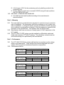
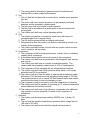
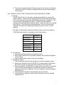
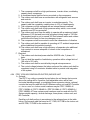
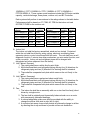
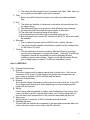
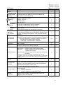
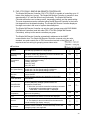
1
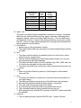
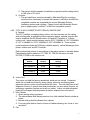
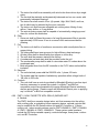
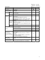
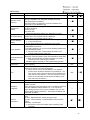
HVAC Guide Specifications Multi Indoor Unit, Variable Capacity, Mini-splits – R2-Series and Y-Series Section 15700 – Mechanical HVAC Size Range: 6 TO 8.5 TONS NOMINAL Mitsubishi Model Number: PURY-80TMU-A R2-SERIES (SIMULTANEOUS COOL/HEAT MODEL) PURY-100TMU-A R2-SERIES (SIMULTANEOUS COOL/HEAT MODEL) PUHY-80TMU-A Y-SERIES (COOL/HEAT MODEL) PUHY-100TMU-A Y-SERIES (COOL/HEAT MODEL) Part 1 – General 1.01 SYSTEM DESCRIPTION The variable capacity, heat pump heat recovery air conditioning system shall be a Mitsubishi Electric CITY MULTI VRFZ (Variable Refrigerant Flow Zoning) System. The CITY MULTI VRFZ systems are the R2-Series (simultaneous heat and cooling) split system and Y-Series (cool/heat) split system. The R2-Series system shall consist of multiple indoor units, DDC (Direct Digital Controls) controls, BC (Branch Circuit) controller and PURY series outdoor unit. Outdoor unit model numbers may be PURY-80TMU-A or PURY-100TMU-A. Up to 16 indoor units may be connected to a single PURY-100TMU-A outdoor unit and up to 15 indoor units may be connected to a single PURY-80TMU-A outdoor unit. Each indoor unit can be independently controlled. The R2-Series is a vertical discharge, 208/230 volt, three phase outdoor unit. The Y-Series system shall consist of multiple indoor units, DDC (Direct Digital Controls) controls, and PUHY outdoor unit. Outdoor unit model numbers may be PUHY-80TMU-A or PUHY-100TMU.-A Up to 16 indoor units may be connected to a single PUHY-100TMU-A outdoor unit and up to 13 indoor units may be connected to a single PUHY-80TMU-A outdoor unit. Each indoor unit can be independently controlled. The Y-Series is a vertical discharge, 208/230 volt three phase outdoor unit. 1.02 QUALITY ASSURANCE A. The units shall be listed by Electrical Laboratories (ETL) and bear the ETL label. B. All wiring shall be in accordance with the National Electrical Code (N.E.C.). C. The units shall be manufactured in a facility registered to ISO 9001 and ISO14001 which is a set of standards applying to environmental protection set by the International Standard Organization (ISO). 1 1.03 D. A full charge of R-22 for the condensing unit only shall be provided in the condensing unit. E. System efficiency shall meet or exceed 8.5 EER during full load conditions and 18.0 EER at 50% load. DELIVERY, STORAGE AND HANDLING A. Unit shall be stored and handled according to the manufacturer’s recommendation. Part 2 – Warranty 2.01 2.02 2.03 The units shall have a manufacturer’s warranty for a period of one (1) year from date of installation. The compressor shall have a warranty of six (6) years from date of installation. If, during this period, any part should fail to function properly due to defects in workmanship or material, it shall be replaced or repaired at the discretion of the manufacturer. This warranty does not include labor. Manufacturer shall have a minimum of twenty years of HVAC experience in the U.S. market. The CITY MULTI VRFZ system must be installed by a Mitsubishi authorized dealer with extensive CITY MULTI training. The mandatory contractor service and install training to be performed by the manufacturer. Part 3 – Performance 3.01 3.02 The CITY MULTI R2-Series system shall perform in accordance to the ratings shown in the table below. These ratings must include Integrated Part Load Values (IPLV) as well as simultaneous operation comparisons. Performance shall be: System Model PURY-100TMU-A 100% @ 80°F O/D Standard Seasonal Load Capacity Cooling Capacity System Watt EER 101,664 10,890 9.3 System Model PURY-100TMU-A 50% @ 80°F O/D System Total Capacity Part Load Cooling Capacity System Watt EER 51,566 4,440 11.6 System Model PURY-100TMU-A 100% @ 45°F O/D Standard Seasonal Load Capacity Heating Capacity System Watt COP 107,136 11,700 2.68 System Model PURY-100TMU-A 50% @ 45°F O/D System Total Capacity Part Load Heating Capacity System Watt COP 53,568 4,520 3.47 2 3.03 Cooling and heating simultaneous performance: System Model PURY-100TMU-A 100% @ 45°F O/D 3.04 3.05 Heat Recovery Capacity Cooling/Heating Capacity Capacity System HRE Cooling Heating Watt 20,500 20,800 7,640 5.40 The City Multi Y-Series shall perform in accordance to the ratings shown in the table below. These ratings must include Integrated Part Load Values (IPLV). Performance shall be: System Model PUHY-100TMU-A 100% @ 80°F O/D Standard Seasonal Load Capacity Cooling Capacity System Watt EER 101,664 10,890 9.3 System Model PUHY-100TMU-A 50% @ 80°F O/D System Total Capacity Part Load Cooling Capacity System Watt EER 51,566 4,440 11.6 System Model PUHY-100TMU_A 100% @ 45°F O/D Standard Seasonal Load Capacity Heating Capacity System Watt COP 107,136 11,700 2.68 System Model PUHY-100TMU-A 50% @ 45°F O/D System Total Capacity Part Load Heating Capacity System Watt COP 53,568 4,520 3.47 Part 4 – Products 4.01 R2-SERIES OUTDOOR UNIT A. General: The R2-Series consists of the PURY outdoor unit, Branch Circuit (BC) Controller, indoor units, and controls network. The R2-Series PURY outdoor unit is designed specifically for use with CITY MULTI VRFZ components. The PURY outdoor units are equipped with multiple circuit boards that interface to the controls system and perform all functions necessary for operation. The outdoor unit must have a powder coated finish. The outdoor unit shall be completely factory assembled, piped and wired. Each unit must be run tested at the factory. 1. The sum of connected capacity of all indoor air handlers shall range from 50% to 150% of outdoor rated capacity. 2. Outdoor unit shall have a sound rating no higher than 57 dB(A). 3. Both refrigerant lines from the outdoor unit to the BC (Branch Circuit) controller shall be insulated. B. Unit Cabinet: 3 C. D. E. F. 1. The casing shall be fabricated of galvanized steel, bonderized and finished with a powder coated baked enamel. Fan: 1. The unit shall be furnished with one direct drive, variable speed propeller type fan. 2. The motor shall have inherent protection, be permanently lubricated bearings, and be completely variable speed. 3. The fan motor shall be mounted for quiet operation. 4. The fan shall be provided with a raised guard to prevent contact with moving parts. 5. The outdoor unit shall have vertical discharge airflow. Coil: 1. The outdoor coil shall be of nonferrous construction with lanced or corrugated plate fins on copper tubing. 2. The coil shall be protected with an integral metal guard. 3. Refrigerant flow from the outdoor unit shall be controlled by means of an inverter driven compressor. 4. The outdoor coil shall include 4 circuits with two position valves for each circuit, except for the last stage. Compressor: 4. The compressor shall be a high performance, inverter driven, modulating capacity scroll compressor. 5. A crankcase heater shall be factory mounted on the compressor. 6. The outdoor unit shall have an accumulator with refrigerant level sensors and controls. 7. The outdoor unit shall have an inverter to modulate capacity. The capacity shall be completely variable down to 16% of rated capacity. 8. The compressor will be equipped with an internal thermal overload. 9. The outdoor unit shall have a high pressure safety switch, over-current protection and DC bus protection. 10. The outdoor unit must have the ability to operate with a maximum height difference of 160 feet and have total refrigerant tubing length of 720 feet. The greatest length is not to exceed 325 feet between indoor and outdoor units without the need for line size changes or traps. 11. The compressor shall be mounted to avoid the transmission of vibration. 12. The outdoor unit shall be capable of operating at 0°F ambient temperature without additional low ambient controls. 13. The outdoor unit shall have a high efficiency oil separator plus additional logic controls to ensure adequate oil volume in the compressor is maintained. Electrical: 1. The outdoor unit electrical power shall be 208/230 volts, 3 phase, 60 hertz. 2. The unit shall be capable of satisfactory operation within voltage limits of 188 volts to 253 volts. 3. The outdoor unit shall be controlled by integral microprocessors. 4 4. The control voltage between the indoor units and the outdoor unit shall be completed using a 2-conductor shielded cable to provide total integration of the system. 4.02 BRANCH CIRCUIT (BC) CONTROLLER FOR R2-SERIES SYSTEMS A. General: The BC (Branch Circuit) Controller is designed specifically for use with R2Series systems. These units are equipped with a circuit board that interfaces to the control system and perform all functions necessary for operation. The unit must have a galvanized steel finish. The BC Controller shall be completely factory assembled, piped and wired. Each unit must be run tested at the factory. This unit must be mounted indoors. The sum of connected capacity of all indoor air handlers shall range from 50% to 150% of rated capacity. Each BC controller shall operate the number of indoor units not exceeding 32,000 Btu/h per branch in accordance with the table below. BC Model Number Number of Branches CMB-104NU-F 4 CMB-105NU-F 5 CMB-106NU-F 6 CMB-108NU-F 8 CMB-1010NU-F 10 CMB-1013NU-F 13 CMB-1016NU-F 16 B. Unit Cabinet: 1. The casing shall be fabricated of galvanized steel. 2. Each cabinet shall house a liquid-gas separator and multiple refrigeration control valves. 3. The unit shall house a tube-in-tube heat exchanger. C. Refrigerant valves: 1. The unit shall be furnished with multiple two position refrigerant valves. 2. Each circuit shall have one (32,000 BTUH or smaller indoor unit section) two-position liquid line valve and a two-position suction line valve. 3. When connecting a 32,000 BTUH or larger indoor unit section, two branch circuits must be joined together at the branch controller to deliver an appropriate amount of refrigerant. The two refrigerant valves will operate simultaneously. 4. The refrigerant connections must be flare-type connections 5. Linear electronic expansion valves shall be used to control the variable refrigerant flow. 5 D. Integral Drain Pan: 1. An integral condensate pan and drain shall be provided. E. Electrical: 1. The unit electrical power shall be 208/230 volts, 1 phase, 60 hertz. 2. The unit shall be capable of satisfactory operation within voltage limits of 188 volts to 254 volts. 3. The BC Controller shall be controlled by integral microprocessors. 4. The control voltage between the indoor units and the outdoor unit shall be communicated on a 2-conductor shielded cable. 4.03 Y-SERIES OUTDOOR UNIT A. General: The Y-Series consists of the PUHY outdoor unit, indoor units, and controls network. The Y-Series PUHY outdoor unit is designed specifically for use with CITY MULTI VRFZ components. The PUHY outdoor units are equipped with multiple circuit boards that interface to the controls system and perform all functions necessary for operation. The outdoor unit must have a powder coated finish. The outdoor unit shall be completely factory assembled, piped and wired. Each unit must be run tested at the factory. 1. The sum of connected capacity of all indoor air handlers shall range from 50% to 130% of outdoor rated capacity. 2. Outdoor unit shall have a sound rating no higher than 57 dB(A). 3. Both refrigerant lines from the outdoor unit to indoor units shall be insulated. B. Unit Cabinet: 1. The casing shall be fabricated of galvanized steel, bonderized and finished with a powder coated baked enamel. C. Fan: 1. The unit shall be furnished with one direct drive, variable speed propeller type fan. 2. The motor shall have inherent protection, be permanently lubricated bearings, and be completely variable speed. 3. The fan motor shall be mounted for quiet operation. 4. The fan shall be provided with a raised guard to prevent contact with moving parts. 5. The outdoor unit shall have vertical discharge airflow. D. Coil: 1. The outdoor coil shall be of nonferrous construction with lanced or corrugated plate fins on copper tubing. 2. The coil shall be protected with an integral metal guard. 3. Refrigerant flow from the outdoor unit shall be controlled by means of an inverter driven compressor. 4. The outdoor coil shall include 4 circuits with two position valves for each circuit, except for the last stage. E. Compressor: 6 1. The compressor shall be a high performance, inverter driven, modulating capacity scroll compressor. 2. A crankcase heater shall be factory mounted on the compressor. 3. The outdoor unit shall have an accumulator with refrigerant level sensors and controls. 4. The outdoor unit shall have an inverter to modulate capacity. The capacity shall be completely variable down to 16% of rated capacity. 5. The compressor will be equipped with an internal thermal overload. 6. The outdoor unit shall have a high pressure safety switch, over-current protection and DC bus protection. 7. The outdoor unit must have the ability to operate with a maximum height difference of 160 feet and have total refrigerant tubing length of 720 feet. The greatest length is not to exceed 325 feet between indoor and outdoor units without the need for line size changes or traps. 8. The compressor shall be mounted to avoid the transmission of vibration. 9. The outdoor unit shall be capable of operating at 0°F ambient temperature without additional low ambient controls. 10. The outdoor unit shall have a high efficiency oil separator plus additional logic controls to ensure adequate oil volume in the compressor is maintained. F. Electrical: 1. The outdoor unit electrical power shall be 208/230 volts, 3 phase, 60 hertz. 2. The unit shall be capable of satisfactory operation within voltage limits of 188 volts to 253 volts. 3. The outdoor unit shall be controlled by integral microprocessors. 4. The control voltage between the indoor units and the outdoor unit shall be completed using a 2-conductor shielded cable to provide total integration of the system. 4.04 PDFY (CEILING-CONCEALED DUCTED) INDOOR UNIT A. General: The PDFY is a ceiling concealed ducted indoor fan coil design that mounts above the ceiling with a 2-position, field adjustable return and a fixed horizontal discharge supply, a modulating linear expansion device, optional controls that may be used with the R2-Sseries outdoor unit and BC Controller or Y-Series outdoor unit. Indoor model numbers may be PDFY-10NMU-A / PDFY-16NMU-A / PDFY-24NMU-A / PDFY32-NMU-A / PDFY-40NMU-A / PDFY-48NMU-A These system model numbers must be used with the R2Series variable capacity, vertical discharge, three-phase, outdoor unit, and BC Controller. Each fan coil shall perform in accordance to the ratings shown in the table below. Performance shall be based on 67° FWB, 80° FDB for the indoor unit and 95°FDB, 75°FWB for the outdoor unit. 7 PDFY-10NAMU-A Btu/h Coolin g 9,500 PDFY-16NAMU-A 15,700 18,700 PDFY-24NAMU-A 23,600 25,400 PDFY-32NAMU-A 31,000 34,000 PDFY-40NAMU-A 40,500 45,000 PDFY-48NAMU-A 46,500 51,000 System Model Number Btu/h Heating 10,800 B. Indoor Unit. The indoor unit shall be factory assembled, wired and run tested. Contained within the unit shall be all factory wiring, piping, electronic modulating linear expansion device, control circuit board and fan motor. The unit shall have a self-diagnostic function, 3-minute time delay mechanism, and an auto restart function. Indoor unit and refrigerant pipes will be charged with dehydrated air before shipment from the factory. C. Unit Cabinet: 1. Space saving, ceiling concealed, ducted. 2. The cabinet panel shall have provisions for a field installed filtered outside air intake. D. Fan: 1. The indoor unit fan shall be an assembly with one or two Sirocco fan(s) direct driven by a single motor. 2. The fan shall be statically and dynamically balanced and run on a motor with permanently lubricated bearings. 3. The indoor fan shall consist of four (4) speeds, High, Mid1, Mid2, and Low, 2 of which are selectable on the room controller. 4. The indoor unit shall have a ducted air outlet system and ducted return air system. E. Filter: 1. Return air shall be filtered by means of a field supplied, field installed return air filter. F. Coil: 1. The indoor coil shall be of nonferrous construction with smooth plate fins on copper tubing. 2. The tubing shall have inner grooves for high efficiency heat exchange. 3. All tube joints shall be brazed with phos-copper or silver alloy. 4. The coils shall be pressure tested at the factory. 5. A condensate pan and drain shall be provided under the coil. 6. The condensate shall be gravity drained from the fan coil. 7. Both refrigerant lines from the BC controller to the PDFY indoor units shall be insulated. G. Electrical: 1. The unit electrical power shall be 208/230 volts, 1 phase, 60 hertz. 8 2. The system shall be capable of satisfactory operation within voltage limits of 188 volts to 253 volts. H. Controls: 1. This unit shall have controls provided by Mitsubishi Electric to perform input functions necessary to operate the system. LonWorks® and BACnet compatible controls are acceptable but require Mitsubishi Electric interfacing devices and software. Please consult with Mitsubishi Electric prior to applying any LonWorks® or BACnet compatible controls. 4.05 PLFY (4-WAY CASSETTE WITH GRILLE) INDOOR UNIT A. General: The PLFY shall be a cassette design indoor unit that recesses into the ceiling with a ceiling grille, a modulating linear expansion device, optional controls that may be used with the R2-Series outdoor unit and BC Controller or Y-Series outdoor unit. Indoor model numbers may be PLFY-12NAMU-A / PLFY-20NAMUA / PLFY-24NAMU-A / PLFY-32NAMU-A / PLFY-40NAMU-A. These system model numbers include the R2-Series variable capacity, vertical discharge, three phase, outdoor unit, and BC Controller. Each system shall perform in accordance to the ratings shown in the table below. Performance shall be based on 67° FWB, 80° FDB for the indoor unit and 95°FDB,75°FWB for the outdoor unit. System Model Number PLFY-12NAMU-A BTU/h Cooling 12,000 BTU/h Heating 13,000 PLFY-20NAMU-A 20,000 22,500 PLFY-24NAMU-A 24,000 26,500 PLFY-32NAMU-A 32,000 36,000 PLFY-40NAMU-A 40,000 39,000 B. Indoor Unit. The indoor unit shall be factory assembled, wired and run tested. Contained within the unit shall be all factory wiring, piping, electronic modulating linear expansion device, control circuit board and fan motor. The unit shall have a selfdiagnostic function, 3-minute time delay mechanism, an auto restart function, an emergency operation function and a test run switch. Indoor unit and refrigerant pipes will be charged with dehydrated air before shipment from the factory. C. Unit Cabinet: 1. Space saving ceiling recessed. 2. The cabinet panel shall have provisions for a field installed filtered outside air intake. 3. Branch ducting shall be allowed from cabinet. 4. Four-way grille shall be fixed to bottom of cabinet allowing, two, three or fourway blow. D. Fan: 9 E. F. G. H. 4.06 1. The indoor fan shall be an assembly with a turbo fan direct driven by a single motor. 2. The fan shall be statically and dynamically balanced and run on a motor with permanently lubricated bearings. 3. The indoor fan shall consist of four (4) speeds, High, Mid1, Mid2, and Low, two of which may be selected by the room controller. 4. The indoor unit shall have an adjustable air outlet system offering 4-way airflow, 3-way airflow, or 2-way airflow. 5. The auto air swing vanes shall be capable of automatically swinging up and down for uniform air distribution. Filter: 1. Return air shall be filtered by means of a long-life permanent filter to provide approximately 2,500 hours of use in a normal office environment before cleaning. Coil: 1. The indoor coil shall be of nonferrous construction with smooth plate fins on copper tubing. 2. The tubing shall have inner grooves for high efficiency heat exchange. 3. All tube joints shall be brazed with phos-copper or silver alloy. 4. The coils shall be pressure tested at the factory. 5. A condensate pan and drain shall be provided under the coil. 6. The condensate pump shall be able to raise drain water 33 inches above the condensate pan. 7. Both refrigerant lines from the BC controller to the PLFY indoor units shall be insulated. Electrical: 1. The unit electrical power shall be 208/230 volts, 1 phase, 60 hertz. 2. The system shall be capable of satisfactory operation within voltage limits of 188 volts to 253 volts. Controls: 1. This unit shall have a controls provided by Mitsubishi Electric to perform input functions necessary to operate the system. LonWorks® and BACnet compatible controls are acceptable but require Mitsubishi Electric interfacing devices and software. Please consult with Mitsubishi Electric prior to applying any LonWorks® or BACnet compatible controls. PMFY (1-WAY CASSETTE WITH GRILLE) INDOOR UNIT A. General: The PMFY shall be a cassette design indoor unit that recesses into the ceiling with a ceiling grille, a modulating linear expansion device, optional controls that may be used with the R2-Series outdoor unit and BC Controller or Y-Series outdoor unit. Indoor model numbers may be PMFY-8NAMU-A / PMFY-10NAMUA / PMFY-12NAMU-A / PMFY-16NAMU-A. These system model numbers include the R2-Series variable capacity, vertical discharge, three phase, outdoor unit, and BC Controller. 10 Each system shall perform in accordance to the ratings shown in the table below. Performance shall be based on 67° FWB, 80° FDB for the indoor unit and 95°FDB, 75°FWB for the outdoor unit. System Model Number PMFY-8NAMU-A BTU/h Cooling 8,000 BTU/h Heating 9,000 PMFY-10NAMU-A 10,000 11,000 PMFY-12NAMU-A 12,000 13,500 PMFY-16NAMU-A 16,000 17,000 B. Indoor Unit. The indoor unit shall be factory assembled, wired and run tested. Contained within the unit shall be all factory wiring, piping, electronic modulating linear expansion device, control circuit board and fan motor. The unit shall have a selfdiagnostic function, 3-minute time delay mechanism, an auto restart function, an emergency operation function and a test run switch. Indoor unit and refrigerant pipes will be charged with dehydrated air before shipment from the factory. C. Unit Cabinet: 1. Space saving ceiling recessed. 2. The cabinet panel shall have provisions for a field installed filtered outside air intake. 3. Branch ducting shall be allowed from cabinet. 4. Four-way grille shall be fixed to bottom of cabinet allowing, two, three or four-way blow. D. Fan: 1. The indoor fan shall be an assembly with a sirocco fan direct driven by a single motor. 2. The fan shall be statically and dynamically balanced and run on a motor with permanently lubricated bearings. 3. The indoor fan shall consist of two (2)speeds, High and Low, two of which may be selected by the room controller. E. Filter: 1. Return air shall be filtered by means of a long-life permanent filter to provide approximately 2,500 hours of use in a normal office environment before cleaning. F. Coil: 1. The indoor coil shall be of nonferrous construction with smooth plate fins on copper tubing. 2. The tubing shall have inner grooves for high efficiency heat exchange. 3. All tube joints shall be brazed with phos-copper or silver alloy. 4. The coils shall be pressure tested at the factory. 5. A condensate pan and drain shall be provided under the coil. 6. The condensate pump shall be able to raise drain water 33 inches above the condensate pan. 11 7. Both refrigerant lines to and from the PMFY indoor units shall be insulated. G. Electrical: 1. The unit electrical power shall be 208/230 volts, 1 phase, 60 hertz. 2. The system shall be capable of satisfactory operation within voltage limits of 188 volts to 253 volts. H. Controls: 1. This unit shall have a controls provided by Mitsubishi Electric to perform input functions necessary to operate the system. LonWorks® and BACnet compatible controls are acceptable but require Mitsubishi Electric interfacing devices and software. Please consult with Mitsubishi Electric prior to applying any LonWorks® or BACnet compatible controls. 4.07 PKFY (WALL-MOUNTED) INDOOR UNIT A. General: The PKFY shall consist of a slim silhouette, compact wall mounted indoor unit section with a modulating linear expansion device, optional controls that may be used with the R2-Sseries outdoor unit and BC Controller or Y-Series outdoor unit. Indoor model numbers may be PKFY-08NAMU-A / PKFY-12NGMU-A / PKFY-20NFMU-A / PKFY32-NFMU-A /. These system model numbers include the R2-Series variable capacity, vertical discharge, three phase, outdoor unit, and BC Controller. Each system shall perform in accordance to the ratings shown in the table below. Performance shall be based on 67° FWB, 80° FDB for the indoor unit and 95°FDB,75°FWB for the outdoor unit. System Model Number PKFY-08NAMU-A Btu/h Cooling 8,000 BTU/h Heating 9,000 PKFY-12NGMU-A 12,000 13,500 PKFY-20NFMU-A 20,000 22,500 PKFY-32NFMU-A 32,000 35,500 B. Indoor Unit The indoor unit shall be factory assembled, wired and run tested. Contained within the unit shall be all factory wiring, piping, electronic modulating linear expansion device, control circuit board and fan motor. The unit shall have a selfdiagnostic function, 3-minute time delay mechanism, an auto restart function, and a test run switch. Indoor unit and refrigerant pipes will be charged with dehydrated air before shipment from the factory. C. Unit Cabinet: 1. The casing shall have a white finish. 2. Multi directional drain and refrigerant piping offering four (4) directions for refrigerant piping and two (2) directions for draining shall be standard. 12 D. E. F. G. H. 3. There shall be a separate back plate which secures the unit firmly to the wall. Fan: 1. The indoor fan shall be an assembly with one or two line-flow fan(s) direct driven by a single motor. 2. The fan shall be statically and dynamically balanced and run on a motor with permanently lubricated bearings. 3. A manual adjustable guide vane shall be provided with the ability to change the airflow from side to side (left to right). 4. A motorized air sweep louver shall provide an automatic change in airflow by directing the air up and down to provide uniform air distribution. 5. The indoor fan shall consist of four (4) speeds, High, Mid1, Mid2, and Low, two of which are selectable by the room controller. Filter: 1. Return air shall be filtered by means of an easily removable washable filter. Coil: 1. The indoor coil shall be of nonferrous construction with smooth plate fins on copper tubing. 2. The tubing shall have inner grooves for high efficiency heat exchange. 3. All tube joints shall be brazed with phos-copper or silver alloy. 4. The coils shall be pressure tested at the factory. 5. A condensate pan and drain shall be provided under the coil. 6. Both refrigerant lines from the BC controller to the PKFY indoor units shall be insulated. Electrical: 1. The unit electrical power shall be 208/230 volts, 1 phase, 60 hertz. 2. The system shall be capable of satisfactory operation within voltage limits of 188 volts to 253 volts. Controls: 1. This unit shall have controls provided by Mitsubishi Electric to perform input functions necessary to operate the system. LonWorks® and BACnet compatible controls are acceptable but require Mitsubishi Electric interfacing devices and software. Please consult with Mitsubishi Electric prior to applying any LonWorks® or BACnet compatible controls. 4.08 PFFY (FLOOR MOUNTED-EXPOSED or FLOOR MOUNTED-CONCEALED) INDOOR UNIT A. General: The PFFY shall consist of a slim silhouette, compact wall mounted indoor section with a modulating linear expansion device, optional controls that may be used with the R2-Sseries outdoor unit and BC Controller or Y-Series outdoor unit. Indoor model numbers may be for floor mounted-exposed - PFFY-08NEMU-A / PFFY-10NEMU-A / PFFY-12NEMU-A / PFFY-16NEMU-A / PFFY-20NEMU-A / PFFY24-NEMU-A and for floor mounted-concealed - PFFY-08NRMU-A/ PFFY- 13 10NRMU-A / PFFY-12NRMU-A / PFFY-16NEMU-A / PFFY-20NRMU-A / PFFY24-NRMU-A. These system model numbers include the R2-Series variable capacity, vertical discharge, three phase, outdoor unit, and BC Controller. Each system shall perform in accordance to the ratings shown in the table below. Performance shall be based on 67° FWB, 80° FDB for the indoor unit and 95°FDB,75°FWB for the outdoor unit. System Model Number PFFY-08NEMU-A Btu/h Cooling 8,000 BTU/h Heating 9,000 System Model Number PFFY-08NRMU-A Btu/h Cooling 8,000 BTU/h Heating 9,000 PFFY-10NEMU-A 10,000 11,200 PFFY-10NRMU-A 10,000 11,200 PFFY-12NEMU-A 12,000 13,500 PFFY-12NRMU-A 12,000 13,500 PFFY-16NEMU-A 16,000 17,000 PFFY-16NRMU-A 16,000 17,000 PFFY-20NEMU-A 20,000 21,000 PFFY-20NRMU-A 20,000 21,000 PFFY-24NEMU-A 24,000 24,800 PFFY-24NRMU-A 24,000 24,800 B. Indoor Unit The indoor unit shall be factory assembled, wired and run tested. Contained within the unit shall be all factory wiring, piping, electronic modulating linear expansion device, control circuit board and fan motor. The unit shall have a selfdiagnostic function, 3-minute time delay mechanism, an auto restart function, and a test run switch. Indoor unit and refrigerant pipes will be charged with dehydrated air before shipment from the factory. C. Unit Cabinet, Exposed: 1. The casing shall have a white Acrylic paint finish. 2. Multi directional drain and refrigerant piping offering four (4) directions for refrigerant piping and two (2) directions for draining shall be standard. 3. There shall be a separate back plate which secures the unit firmly to the wall. D. Unit Cabinet, Recessed: 1. The casing shall have a galvanized sheet metal finish. 2. Multi directional drain and refrigerant piping offering four (4) directions for refrigerant piping and two (2) directions for draining shall be standard. 3. There shall be a separate back plate which secures the unit firmly to the wall. E. Fan: 1. The indoor fan shall be an assembly with one or two line-flow fan(s) direct driven by a single motor. 2. The fan shall be statically and dynamically balanced and run on a motor with permanently lubricated bearings. 3. A manual adjustable guide vane shall be provided with the ability to change the airflow from side to side (left to right). 4. A motorized air sweep louver shall provide an automatic change in airflow by directing the air up and down to provide uniform air distribution. 14 F. G. H. I. 5. The indoor fan shall consist of four (4) speeds, High, Mid1, Mid2, and Low, two of which are selectable by the room controller. Filter: 1. Return air shall be filtered by means of an easily removable washable filter. Coil: 7. The indoor coil shall be of nonferrous construction with smooth plate fins on copper tubing. 8. The tubing shall have inner grooves for high efficiency heat exchange. 9. All tube joints shall be brazed with phos-copper or silver alloy. 10. The coils shall be pressure tested at the factory. 11. A condensate pan and drain shall be provided under the coil. 12. Both refrigerant lines from the BC controller to the PKFY indoor units shall be insulated. Electrical: 1. The unit electrical power shall be 208/230 volts, 1 phase, 60 hertz. 2. The system shall be capable of satisfactory operation within voltage limits of 188 volts to 253 volts. Controls: 1. This unit shall have controls provided by Mitsubishi Electric to perform input functions necessary to operate the system. LonWorks® and BACnet compatible controls are acceptable but require Mitsubishi Electric interfacing devices and software. Please consult with Mitsubishi Electric prior to applying any LonWorks® or BACnet compatible controls. Part 5- CONTROLS 5.01 Physical characteristics: A. General: The control system must be plastic material with a neutral color. Each control must have a LCD (Liquid Crystal Display) that shows room temperature, set point, mode of operation (on/off/cool/heat) and fan speed. 5.02 Electrical Characteristics A. General: The electrical voltage from each circuit board to the controls shall be 12 volts DC. The voltage may fluctuate up or down depending on communication packets being sent and received. B. Wiring: Control wiring shall be installed in a daisy chain configuration from indoor unit to indoor unit then to the BC controller and outdoor unit. Control wiring shall run from the indoor unit terminal block to the controller associated with that unit. C. Wiring size: Wiring shall be 2-conductor 18 AWG. stranded wire with a shield. D. Shielding the cable: The wire shall be shielded and connected to the appropriate terminals within the indoor units and outdoor unit as well as the BC controller. 15 5.03 CITY MULTI Controls Network (CMCN) The CITY MULTI Controls Network (CMCN) consists of remote controllers, timers, centralized controllers, and integrated system software communicating over a highspeed communication bus with optional interconnection and control via a network PC. The CITY MULTI Controls Network can support operation monitoring, scheduling, error e-mail distribution, personal browsers, tenant billing, maintenance support, and integration with Building Management Systems (BMS) using either our LonWorks® or BACnet interfaces. All of which unite to provide the best in comfort conditioning control. The below figure illustrates the CMCN System Configuration. CMCN System Configuration 5.04 CMCN: Remote Controllers CMCN remote controllers can operate all CITY MULTI indoor units. The wiring for the remote controllers is simple, non-polar, two-wire connections. All remote controllers are wall-mounted and contain a microprocessor that constantly monitors operation to maintain smooth indoor unit operation. Set temperature can be adjusted in increments of 2°F. In the event of an abnormality, the remote controller will display a four-digit error code and the indoor unit address. A. PAR-20MAU-E: MA REMOTE CONTROLLER The MA Remote Controller (PAR-20MAU-E) is capable of controlling up to 16 indoor units (defined as 1 group). The MA Remote Controller is approximately 5”x5” in size and is similar in appearance to the ME Remote Controller. The MA Remote Controller controls the following grouped operation: On/Off, Operation Mode (cool, heat, auto (R2Series only), dry, and fan), temperature setting, fan speed setting, and airflow direction setting. In terms of timer operation, one ON/OFF setting can be defined per day. The room temperature can be sensed either at the MA Remote Controller or at the indoor unit dependent on dipswitch setting. The MA Remote Controller displays a four-digit error code in the event of system abnormality/error. 16 The MA Remote Controller can only be used in same group with other PAR-20MAU (MA Remote Controllers) and with PAC-YT51CRA (Simple MA Remote Controllers), with up to two remote controllers per group. The MA Remote Controller automatically addresses to the M-NET communication bus. The MA Remote Controller connects using two-wire, stranded, non-polar control wire to TB15 connection terminal on the indoor unit. It requires cross-over wiring for grouping across indoor units. The MA Remote Controller can be wired to connect to the Program Timer to expand timer operation and provide set-back operation. ■Functions Item ON/OFF Operation mode switching Temperature setting Fan Speed setting Air Flow Direction setting Permit/Prohibit local operation Indoor unit intake temperature Error Test run External input/output Description Run and stop operation for a single group Switches between Cool/Dry/Auto/Fan/Heat. Operation modes vary depending on the air conditioner unit. Auto mode is in the R2 Series only. Sets the temperature for a single group Range of temperature setting Cool/Dry: 65ºF-87ºF Heat: 61ºF-83ºF Auto: 65ºF-83ºF Models with 4 air flow speed settings: Hi/Mid-2/Mid-1/Low Models with 3 air flow speed settings: Hi/Mid/Low Models with 2 air flow speed settings: Hi/Low Air flow direction angles 100%-80%-60%-40%, Swing, Louver ON/OFF Air flow direction settings vary depending on the model. Individually prohibit operation of each local remote control function (Start/Stop, Change operation mode, Set temperature, Reset filter). *1: When the local remote controller inactivation command is received from the master system controller, “-CENTRALLY CONTROLLED-“ is displayed. Measures the intake temperature of the indoor unit when the indoor unit is operating When an error is currently occurring on an air conditioner unit, the afflicted unit and the error code are displayed Operates air conditioner units in test run mode. By connecting the Program timer “PAC-YT32PTA”, a weekly schedule can be controlled. External start/stop control and emergency stop is not supported. Operation Display ○ ○ ○ ○ ○ ○ ○ ○ ○ ○ N/A ○* N/A N/A ○ ○ 1 ○ □ ○ ○ 17 B. PAR-F27MEA-US-E: ME REMOTE CONTROLLER The ME Remote Controller (PAR-F27MEA-US-E) is capable of controlling up to 16 indoor units (defined as 1 group) from this compact 5”x5” (approximate) wall-mounted controller. The ME Remote Controller can be placed anywhere on the communication bus and does not need to reside in the same room as the indoor unit(s) under its control. The ME Remote Controller controls the following grouped operation for up to sixteen indoor units: On/Off, Operation Mode (cool, heat, auto (R2-Series only), dry, and fan), temperature setting, fan speed setting, and airflow direction setting. The ME Remote Controller has three timer options: one on/off setting defined for one day, repeated daily timer, and auto-off timer function. The ME Remote Controller can limit the set temperature range to a specified range within 65°F to 83°F. The room temperature can be sensed at either the ME Remote Controller or the Indoor Unit dependent on the dipswitch setting. The ME Remote Controller displays a four-digit error code in the event of system abnormality/error. The ME Remote Controller can only be used in same group with a total of two PARF27MEA-US-E (ME Remote Controllers). The ME Remote Controller requires manual addressing using rotary dial switch to the M-NET communication bus. The ME Remote Controller connects using two-wire, stranded, non-polar control wire to TB5 connection terminal on the indoor unit. The ME Remote Controller can be wired to connect to the Program Timer to expand timer operation and provide set-back operation. 18 ■Functions Item ON/OFF Operation mode switching Temperature setting Fan Speed setting Air Flow Direction setting Timer operation Permit/Prohibit local operation Indoor unit intake temperature Error Timer Operations Description Run and stop operation for a single group Switches between Cool/Dry/Auto/Fan/Heat. Operation modes vary depending on the air conditioner unit. Auto mode is in the R2 Series only. Sets the temperature for a single group Range of temperature setting Cool/Dry: 65ºF-87ºF Heat: 61ºF-83ºF Auto: 65ºF-83ºF Models with 4 air flow speed settings: Hi/Mid-2/Mid-1/Low Models with 3 air flow speed settings: Hi/Mid/Low Models with 2 air flow speed settings: Hi/Low Air flow direction angles 100%-80%-60%-40%, Swing, Louver ON/OFF Air flow direction settings vary depending on the model. One ON/OFF setting can be set for one day. By connecting the Program time, set 48 ON/OFF settings every 30 minutes. By loading only one pattern, it can operate as a weekly schedule. Individually prohibit operation of each local remote control function (Start/Stop, Change operation mode, Set temperature, Reset filter). *1: When the local remote controller inactivation command is received from the master system controller, “-CENTRALLY CONTROLLED-“ is displayed. Measures the intake temperature of the indoor unit when the indoor unit is operating When an error is currently occurring on an air conditioner unit, the afflicted unit and the error code are displayed Three timer modes. One day time : ON/OFF setting of one time on one day Daily timer : ON/OFF setting by the One day timer can be repeated for every day Auto OFF timer: OFF timer can be set in a range from 30 minutes to 4 hours. Operation Display ○ ○ ○ ○ ○ ○ ○ ○ ○ ○ ○ ○ N/A ○* ○ □ N/A N/A ○ ○ ○ ○ ○ ○ ○ ○ ○ ○ *Setting of Auto OFF timer automatically activates OFF timer at the next operation. This function can be utilized to prevent the negligence of OFF setting. *Weekly schedule in only one pattern can be employed by connecting Program timer. *2 Test run Set temperature range limit Auto lock function External input/output Operates air conditioner units in test run mode. The range of room temperature setting can be limited by the initial setting. The lowest limit temperature can be made higher than the usual (65ºF) in cool/dry mode, while the upper limit temperature lower than the usual (83ºF) in heat mode. *Function does not work in auto mode setting Setting/releasing of simplified locking for remote control buttons can be performed. • Locking of all buttons • Locking of all buttons except ON/OFF button By connecting the Program timer “PAC-YT32PTA”, a weekly schedule can be controlled. External start/stop control and emergency stop is not supported. 19 1 C. PAC-YT51CRA-E: SIMPLE MA REMOTE CONTROLLER The Simple MA Remote Controller (PAC-YT51CRA-E) is capable of controlling up to 16 indoor units (defined as 1 group). The Simple MA Remote Controller is compact in size, approximately 3”x5” and has limited user functionality. The Simple MA Remote Controller allows the user to change on/off, temperature setting, and fan speed setting. The room temperature can be sensed at either the ME Remote Controller or the Indoor Unit dependent on the dipswitch setting. The Simple MA Remote Controller displays a four-digit error code in the event of system abnormality/error. The Simple MA Remote Controller can only be used in same group with PAR-20MAU (MA Remote Controllers) and/ with other PAC-YT51CRA (Simple MA Remote Controllers), with up to two remote controllers per group. The Simple MA Remote Controller automatically addresses to the M-NET communication bus. The Simple MA Remote Controller connects using two-wire, stranded, non-polar control wire to TB15 connection terminal on the indoor unit. It requires cross-over wiring for grouping across indoor units. ■Functions Item ON/OFF Description Run and stop operation for a single group Air Flow Direction setting Switches between Cool/Dry/Auto/Fan/Heat. Operation modes vary depending on the air conditioner unit. Auto mode is in the R2 Series only. Sets the temperature for a single group Range of temperature setting Cool/Dry: 65ºF-87ºF Heat: 61ºF-83ºF Auto: 65ºF-83ºF Models with 4 air flow speed settings: Hi/Mid-2/Mid-1/Low Models with 3 air flow speed settings: Hi/Mid/Low Models with 2 air flow speed settings: Hi/Low Air flow direction angles 100%-80%-60%-40%, Swing, Louver ON/OFF Air flow direction settings vary depending on the model. Timer Operation Not Available Operation mode switching Temperature setting Fan Speed Setting Permit/Prohibit local operation Indoor unit intake temperature Error Test run External input/output Individually prohibit operation of each local remote control function (Start/Stop, Change operation mode, Set temperature, Reset filter). *1: When the local remote controller inactivation command is received from the master system controller, “-CENTRALLY CONTROLLED-“ is displayed. Measures the intake temperature of the indoor unit when the indoor unit is operating When an error is currently occurring on an air conditioner unit, the afflicted unit and the error code are displayed Operates air conditioner units in test run mode. *2: The display for test run mode will be the same as for normal start/stop (no display “test run”) By connecting the Program timer “PAC-YT32PTA”, a weekly schedule can be controlled. External start/stop control and emergency stop is not supported. Operation Display ○ ○ N/A ○ ○ ○ ○ ○ ○ ○ ○ ○ N/A ○* N/A N/A 1 ○ □ ○ N/A N/A N/A 20 5.05 CMCN: Timers A. PAC-YT32PTA-E: PROGRAM TIMER The Program Timer (PAC-YT32PTA-E) can be used only in conjunction with one PAR20MAU (MA Remote Controller) or with one PAR-F27MEA (ME Remote Controller). The Program Timer controls one indoor unit in terms of on/off or setback in 30-minute intervals over a 24-hour period. The Program Timer supports weekly timer operation via two user-defined modes (Mode A and Mode B) to apply to each day of the week. The timer operation consists of on/off and set-back in 30-minute intervals with up to 48 settings per day. The Program Timer in conjunction with either one MA Remote Controller or one ME Remote Controller will allow the user to program the set-back temperature by 0, 2, 4, 8, 12, or 16°F. The Program Timer supports 48-hour battery backup for timer settings in case power interruption/failure. B. PAC-YT34STA: SCHEDULE TIMER The Schedule Timer (PAC-YT34STA) schedules up to 50 indoor units. The maximum number of indoor units supported per one group is 16. The maximum number of groups supported is 50. The Schedule Timer must be used in conjunction with PAR-20MAU (MA Remote Controllers) and/or PAR-F27MEA (ME Remote Controllers). The Schedule Timer supports up 9 scheduling patterns with up to 16 operations per pattern. Operations include on/off, mode selection (cool, heat), set temperature, and prohibition of remote controller functions (on/off, operation mode change, and set temperature adjustment). Patterns are applied to each group of indoor units on a per-day basis. The minimum time interval is 5-minutes. The Schedule Timer displays a four-digit error code in the event of system abnormality/error. The Schedule Timer must be manually addressed using rotary dial switch to the M-NET communication bus. The Schedule Timer connects to TB7 connection terminal on outdoor unit using PAC-SC50KUA power supply or connects to TB3 connection terminal on the outdoor unit. The Schedule Timer can be used in conjunction with G-50A Centralized Controller which has higher priority but requires change in dipswitch setting. The Schedule timer can be interlocked with a building management system using the external input/output managing function. 21 ■Functions Item Unit control Schedule control One week ON/OFF ON/OFF operations can be carried out collectively or for each group. Timer reset The timer setting details can be disabled collectively. Setting details ON/OFF COOL/HEAT Room temperature setting (19 ºC to 28 ºC) Operation prohibit (ON/OFF, operation mode, setting temperature) Number of setting patterns: Ten (no setting + nine patterns) (Operation for a week can be set by selecting one of ten patterns for each day.) Number of operations: Up to 16 operations can be set in one pattern. Operation Schedule function Description 50 units/50 groups (Maximum 16 units connected in one group) Operation Display ◙ ○ ○ ○ ○ ○ — — ○ — ○ — The item can be set in five-minute units. ○ — Current time and day — Error state — Unit operation state — N/A External input (Timer connection, emergency stop input, etc.) The following can be input with the level signals or pulse signals. Level signal: “Emergency stop input” or “Collective ON/OFF” Pulse signal: “Collective ON/OFF” or “Local remote controller prohibit/permit” One input can be selected from those above. ○ — External output (Error output, operation output) “ON/OFF” and “error/normal” are output with the level signal. Connection position Indoor/outdoor transmission line: Connectable Central system transmission line: Connectable Number of settings Time setting unit Display ○ ○ ○ ○ — — 22 5.06 CMCN: System Controllers A. G-50A Centralized Controller The G-50A Centralized Controller is capable of controlling a maximum of 50 indoor units across multiple CITY MULTI outdoor units. The G-50A Centralized Controller is approximately 5”x12” in size and is powered from a Power Supply Unit (PACSC50KUA). The G-50A Centralized Controller supports operation superceding that of the remote controllers, system configuration, daily/weekly scheduling, monitoring of operation status, and malfunction monitoring. The G-50A Centralized Controller has five basic operation controls which can be applied to an individual indoor unit, a group of indoor units (up to 50 indoor units), or all indoor units (collective batch operation). The basic control set of operation controls for the G-50A Centralized Controller are on/off, operation mode selection (cool, heat, auto (R2-Series only), dry, and fan), temperature setting, fan speed setting, and airflow direction setting. Since the G-50A provides centralized control it can enable or disable operation of local remote controllers. In terms of scheduling, the G-50A Centralized Controller will allow the user to define both daily and weekly schedules with operations consisting of ON/OFF, mode selection, temperature setting (63°F – 87°F), and permit/prohibit of remote controllers. 23 ■Functions Item ON/OFF Operation mode switching Temperature Setting Fan Speed Setting Air Flow Direction setting Timer Operation Permit/Prohibit local operation Indoor unit intake temperature Error Test run Ventilation Equipment External input/output Description Run and stop operation for a single group Switches between Cool/Dry/Auto/Fan/Heat. (Group of LOSSNAY unit: automatic ventilation/vent-heat interchange/normal ventilation) Operation modes vary depending on the air conditioner unit. Auto mode is in the R2 Series only. Range of temperature setting Cool/Dry: 65ºF-87ºF Heat: 61ºF-83ºF Auto: 65ºF-83ºF ٭Range of temperature settings vary depending on model. Models with 4 air flow speed settings: Hi/Mid-2/Mid-1/Low Models with 3 air flow speed settings: Hi/Mid/Low Models with 2 air flow speed settings: Hi/Low Air flow direction angles 100%-80%-60%-40%, Swing, ٭1: Louver cannot be set Air flow direction settings vary depending on the model. For one day, you can set start/stop three times and you can set enable/disable three times. For a week’s schedule, you can store three start/stop patterns and one enable/disable pattern. ٭2: When the time is set, “Timer enabled” is shown on the operation setting screen of the LCD. Individually prohibit operation of each local remote control function (Start/Stop, Change operation mode, Set temperature, Reset filter). ٭3: When the local remote controller inactivation command is received from the master system controller, “Disabled” appears in display on the operation setting screen. Measures the intake temperature of the indoor unit when the indoor unit is operating When an error is currently occurring on an air conditioner unit, the afflicted unit and the error code are displayed ٭4: When an error occurs, the LED flashes. The operation monitor screen shows the abnormal unit by flashing it. The error monitor screen shows the abnormal unit address, error code and source of detection. The error log monitor screen shows the time and date, the abnormal unit address, error code and source of detection This operates air conditioner units in test run mode. This interlocked system settings can be performed by the master system controller. When setting the interlocked system, use the ventilation switch the free plan LOSSNAY settings between “Hi”, “Low” and “Stop”. When setting a group of only free plan LOSSNAY units, you can switch between “Normal ventilation”, “Interchange ventilation” and “Automatic ventilation”. By using accessory cables you can set and monitor the following. Input By level: “Batch start/stop”, “Batch emergency stop” By pulse: “batch start/stop”, “Enable/disable remote controller” Output “start/stop”, “error/Normal” ٭5: Requires the external I/O cables (PAC-YG10HA-E) sold separately. Operation Display ○◙ ○◙ ○◙ ○ ○◙ ○ ○*1◙ ○ ○◙ ○ ○◙ ○*2 ○◙ ○*3 N/A ○ N/A □*4◙ ○ ○ ○ ○ ◙*5 ◙ *6 24 All G-50A Centralized Controllers are equipped with a RJ-45 Ethernet port to support interconnection with a network PC via a closed/direct Local Area Network (LAN), via an Ethernet Hub on a LAN, or via a dial-up router on a LAN. Optional software functions are available so that the building manager can securely log into each G-50A via the PC’s web browser to support operation monitoring, scheduling, error e-mail, personal browser, and maintenance diagnostics. The optional software functions require advance purchasing and can only be activated upon receipt of a license number from Mitsubishi Electric HVAC. These optional software functions can be licensed for a 1-year or 3-year term, subject to renewal and associated fees upon term expiration. B. TG-2000 Integrated System Software The TG-2000 Integrated System Software enables the user to control multiple G-50As and provide enhanced functions such as tenant billing and BACnet from a single, dedicated network PC configured with the TG-2000 software. The TG-2000 configured computer is capable of controlling up to forty G-50A Centralized Controllers with a maximum of 2,000 indoor units across multiple CITY MULTI outdoor units. The TG-2000 software is required if the user wants to simultaneously control more than 1 G-50A from a single PC using a single software session. Optional software features are available through the TG-2000 software including tenant billing and BACnet. These optional software features require the TG-2000 software, advance purchase from the customer, and licensing from Mitsubishi to enable feature activation. These optional software functions can be licensed for a 1-year or 3-year term, subject to renewal and associated fees upon term expiration. 5.07 CMCN: System Integration The CMCN supports integration with Building Management Systems (BMS) via our LonWorks® and BACnet interfaces. A. LMAP03U: LonWorks® Interface The Mitsubishi Electric HVAC LonWorks® interface, LMAP03U, supports up to fifty indoor units with a variety of network variables on a per indoor unit basis. Input variables include, but are not limited to, on/off, operation mode, fan speed, prohibit remote controller, and filter sign reset. Output variables include, but are not limited to, model size, alarm state, error code, and error address. B. PAC-YTG31CDA: BACnet Interface The Mitsubishi Electric HVAC BACnet interface, PAC-YG31CDA, is compliant with BACnet/IP (ANSI/ASHRAE 135-1995, 135a) and UDP/IP of Ethernet (ANSI/ASHRAE 135-1995, 135b). Our BACnet interface requires a dedicated network computer configured with the TG-2000 software and activated BACnet software function via Mitsubishi Electric HVAC issued license for 1-year or 3-year term, subject to renewal and associated fees. The BACnet software license is on a per G-50A basis for a maximum of 50 indoor units controlled by one G-50A Centralized Controller. The BACnet interface supports a maximum of ten G-50A Centralized Controllers for a maximum of 500 indoor units. C. PAC-SC25KAA: K Converter The K Converter (PAC-SC25KAA) is used in conjunction with the G-50A Centralized Controller to provide centralized control for Mr. Slim P-Series (wired) systems. Up to 50 Mr. Slim P-Series (wired) systems can be controlled from the G-50A when the K Converted is installed. The K Converter will translate Mr. Slim error codes to CITY MULTI error codes. 25