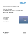
1
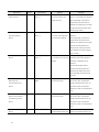
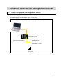
Machine Automation Controller NJ-series
Startup Guide
for Simulink ® PLC Coder™ &
Sysmac Studio
SYSMAC-SE20□□
NJ501-□□□□
NJ301-□□□□
R88D-KN□-ECT
GX-AD0471/DA0271
W529-E1-01
©OMRON, 2013
All rights reserved. No part of this publication may be reproduced, stored in a retrieval system, or transmitted, in any
form, or by any means, mechanical, electronic, photocopying, recording, or otherwise, without the prior written
permission of OMRON.
No patent liability is assumed with respect to the use of the information contained herein. Moreover, because
OMRON is constantly striving to improve its high-quality products, the information contained in this manual is
subject to change without notice. Every precaution has been taken in the preparation of this manual. Nevertheless,
OMRON assumes no responsibility for errors or omissions. Neither is any liability assumed for damages resulting
from the use of the information contained in this publication.
Introduction
The NJ-series Startup Guide for Simulink® PLC Coder™ and Sysmac Studio (hereinafter, may
be referred to as “this Guide”) describes the startup procedures that are required to use a
combination of Simulink® PLC Coder™ from The MathWorks® Inc. and NJ-series CPU Unit for
the first time and the basic operating instructions for the Sysmac Studio. A simple single-axis
positioning example is used for the discussion. You can perform the procedures that are
presented in this Guide to quickly gain a basic understanding of the combination of Simulink®
PLC Coder™ and NJ-series CPU Unit.
This Guide does not contain safety information and other details that are required for actual use.
Thoroughly read and understand the manuals for all of the devices that are used in this Guide
to ensure that the system is used safely. Review the entire contents of these materials,
including all safety precautions, precautions for safe use, and precautions for correct use.
Intended Audience
This guide is intended for the following personnel.
• Personnel in charge of introducing FA systems
• Personnel in charge of designing FA systems
The personnel must also have the following knowledge.
• Knowledge of electrical systems (an electrical engineer or the equivalent)
• Knowledge of MATLAB®/Simulink® from The MathWorks® Inc.
• Knowledge of NJ-series CPU Units
• Knowledge of operation procedure of Sysmac Studio
Applicable Products
This guide covers the following products.
• CPU Units of NJ-series Machine Automation Controllers
• Sysmac Studio Automation Software
• MATLAB®/Simulink® from The MathWorks® Inc.
• Simulink® PLC Coder™ from The MathWorks® Inc.
Special Information
The icons that are used in this Guide are described below.
Precautions for Correct Use
Precautions on what to do and what not to do to ensure proper operation and
performance.
Additional Information
Additional information to read as required.
This information is provided to increase understanding or make operation easier.
1
Terms and Conditions Agreement
Read and understand this catalog.
Please read and understand this catalog before purchasing the products.
Please consult your
OMRON representative if you have any questions or comments.
Warranties.
(a) Exclusive Warranty. Omron’s exclusive warranty is that the Products will be free from defects in
materials and workmanship for a period of twelve months from the date of sale by Omron (or such
other period expressed in writing by Omron). Omron disclaims all other warranties, express or
implied.
(b) Limitations. OMRON MAKES NO WARRANTY OR REPRESENTATION, EXPRESS OR IMPLIED,
ABOUT NON-INFRINGEMENT, MERCHANTABILITY OR FITNESS FOR A PARTICULAR
PURPOSE OF THE PRODUCTS. BUYER ACKNOWLEDGES THAT IT ALONE HAS DETERMINED
THAT THE PRODUCTS WILL SUITABLY MEET THE REQUIREMENTS OF THEIR INTENDED USE.
Omron further disclaims all warranties and responsibility of any type for claims or expenses based on
infringement by the Products or otherwise of any intellectual property right.
(c) Buyer Remedy. Omron’s sole obligation hereunder shall be, at Omron’s election, to (i) replace (in
the form originally shipped with Buyer responsible for labor charges for removal or replacement
thereof) the non-complying Product, (ii) repair the non-complying Product, or (iii) repay or credit Buyer
an amount equal to the purchase price of the non-complying Product; provided that in no event shall
Omron be responsible for warranty, repair, indemnity or any other claims or expenses regarding the
Products unless Omron’s analysis confirms that the Products were properly handled, stored, installed
and maintained and not subject to contamination, abuse, misuse or inappropriate modification.
Return of any Products by Buyer must be approved in writing by Omron before shipment. Omron
Companies shall not be liable for the suitability or unsuitability or the results from the use of Products
in combination with any electrical or electronic components, circuits, system assemblies or any other
materials or substances or environments. Any advice, recommendations or information given orally or
in writing, are not to be construed as an amendment or addition to the above warranty.
See http://www.omron.com/global/
or contact your Omron representative for published information.
Limitation on Liability; Etc.
OMRON COMPANIES SHALL NOT BE LIABLE FOR SPECIAL, INDIRECT, INCIDENTAL, OR
CONSEQUENTIAL DAMAGES, LOSS OF PROFITS OR PRODUCTION OR COMMERCIAL LOSS
IN ANY WAY CONNECTED WITH THE PRODUCTS, WHETHER SUCH CLAIM IS BASED IN
CONTRACT, WARRANTY, NEGLIGENCE OR STRICT LIABILITY.
Further, in no event shall liability of Omron Companies exceed the individual price of the Product on
which liability is asserted.
Suitability of Use.
Omron Companies shall not be responsible for conformity with any standards, codes or regulations
which apply to the combination of the Product in the Buyer’s application or use of the Product. At
Buyer’s request, Omron will provide applicable third party certification documents identifying ratings
2
and limitations of use which apply to the Product. This information by itself is not sufficient for a
complete determination of the suitability of the Product in combination with the end product, machine,
system, or other application or use. Buyer shall be solely responsible for determining appropriateness
of the particular Product with respect to Buyer’s application, product or system. Buyer shall take
application responsibility in all cases.
NEVER USE THE PRODUCT FOR AN APPLICATION INVOLVING SERIOUS RISK TO LIFE OR
PROPERTY OR IN LARGE QUANTITIES WITHOUT ENSURING THAT THE SYSTEM AS A WHOLE
HAS BEEN DESIGNED TO ADDRESS THE RISKS, AND THAT THE OMRON PRODUCT(S) IS
PROPERLY RATED AND INSTALLED FOR THE INTENDED USE WITHIN THE OVERALL
EQUIPMENT OR SYSTEM.
Programmable Products.
Omron Companies shall not be responsible for the user’s programming of a programmable Product,
or any consequence thereof.
Performance Data.
Data presented in Omron Company websites, catalogs and other materials is provided as a guide for
the user in determining suitability and does not constitute a warranty. It may represent the result of
Omron’s test conditions, and the user must correlate it to actual application requirements. Actual
performance is subject to the Omron’s Warranty and Limitations of Liability.
Change in Specifications.
Product specifications and accessories may be changed at any time based on improvements and
other reasons. It is our practice to change part numbers when published ratings or features are
changed, or when significant construction changes are made. However, some specifications of the
Product may be changed without any notice. When in doubt, special part numbers may be assigned
to fix or establish key specifications for your application. Please consult with your Omron’s
representative at any time to confirm actual specifications of purchased Product.
Errors and Omissions.
Information presented by Omron Companies has been checked and is believed to be accurate;
however, no responsibility is assumed for clerical, typographical or proofreading errors or omissions.
3
Precautions
• When building a system, check the specifications for all devices and equipment that will make
up the system and make sure that the OMRON products are used well within their rated
specifications and performances. Safety measures, such as safety circuits, must be
implemented in order to minimize the risks in the event of a malfunction.
• Thoroughly read and understand the manuals for all devices and equipment that will make up
the system to ensure that the system is used safely. Review the entire contents of these
manuals, including all safety precautions, precautions for safe use, and precautions for
correct use.
• Confirm all regulations, standards, and restrictions that the system must adhere to.
• Contact The MathWorks® Inc. for the codes that were outputted from Simulink® PLC
Coder™.
• Applicability of codes that were outputted from Simulink® PLC Coder™ must be judged by
the customer.
• Check the user program for proper execution before you use it for actual operation.
Trademarks
• Sysmac and SYSMAC are trademarks or registered trademarks of OMRON Corporation in
Japan and other countries for OMRON factory automation products.
• EtherCAT® is registered trademark and patented technology, licensed by Beckhoff
Automation GmbH, Germany.
• MATLAB® and Simulink® are registered trademarks of The MathWorks® Inc.
• Microsoft product screen shot(s) reprinted with permission from Microsoft Corporation.
Other company names and product names in this Guide are the trademarks or registered
trademarks of their respective companies.
Software Licenses and Copyrights
The NJ-series CPU Units and Sysmac Studio incorporate certain third party software. The license and
copyright information associated with this software is available at http://www.fa.omron.co.jp/nj_info_e/.
4
Related Manuals
The following manuals are related to the NJ-series Controllers. Use these manuals for reference.
Manual name
Sysmac Studio Version 1
Cat. No.
W504
Model numbers
SYSMAC-SE2□□□
Operation Manual
Application
Description
Learning about the operating
The operating procedures of the Sysmac
procedures and functions of the
Studio are described.
Sysmac Studio.
NJ-series CPU Unit Hardware
W500
User’s Manual
NJ501-□□□□
Learning the basic specifications
An introduction to the entire NJ-series
NJ301-□□□□
of the NJ-series CPU Units,
system is provided along with the following
including introductory information,
information on a Controller built with an
designing, installation, and
NJ501 CPU Unit.
maintenance.
・Features and system configuration
Mainly hardware information is
・Introduction ・Part names and functions
provided.
・General specifications ・Installation and
wiring
・Maintenance and inspection
Use this manual together with the
NJ-series CPU Unit Software User’s
Manual (Cat. No. W501).
NJ-series CPU Unit Software
W501
User’s Manual
NJ501-□□□□
Learning how to program
The following information is provided on a
NJ301-□□□□
and set up an NJ-series CPU Unit.
Controller built with an NJ-series CPU Unit.
Mainly software information is
・CPU Unit operation
provided.
・CPU Unit features
・Initial settings
・Programming based on IEC 61131-3
language specifications
Use this manual together with the
NJ-series CPU Unit Hardware User’s
Manual (Cat. No.W500).
NJ-series CPU Unit Motion
Control USER'S MANUAL
W507
NJ501-□□□□
Learning about motion control
The settings and operation of the CPU Unit
NJ301-□□□□
settings and programming
and programming concepts for motion
concepts.
control are described. Use this manual
together with the NJ-series CPU Unit
Hardware User’s Manual (Cat. No. W500)
and NJ-series CPU Unit Software User’s
Manual (Cat. No. W501).
5
Manual name
NJ-series Instructions
Cat. No.
W502
Reference Manual
Model numbers
Application
Description
NJ501-□□□□
Learning detailed specifications
The instructions in the instruction set
NJ301-□□□□
on the basic instructions of an
(IEC61131-3 specifications) are described.
NJ-series CPU Unit.
When programming, use this manual
together with the NJ-series CPU Unit
Hardware User’s Manual (Cat. No. W500)
and NJ-series CPU Unit Software User’s
Manual (Cat. No. W501).
NJ-series Motion Control
W508
Instructions Reference
NJ501-□□□□
Learning about the specifications
The motion control instructions are
NJ301-□□□□
of the motion control instructions
described.
that are provided by OMRON.
When programming, use this manual
Manual
together with the NJ-series CPU Unit
Hardware User’s Manual (Cat. No. W500),
NJ-series CPU Unit Software User’s
Manual (Cat. No. W501) and NJ-series
CPU Unit Motion Control User’s Manual
(Cat. No. W507).
NJ-series Troubleshooting
W503
Manual
NJ501-□□□□
Learning about the errors that
Concepts on managing errors that may be
NJ301-□□□□
may be detected in an NJ-series
detected in an NJ-series Controller and
Controller.
information on individual errors are
described.
Use this manual together with the
NJ-series CPU Unit Hardware User’s
Manual (Cat. No.W500) and NJ-series
CPU Unit Software User’s Manual (Cat.
No. W501).
AC Servomotors/Servo Drives
I576
(Built-in EtherCAT
R88D-KN□-ECT/
Learning detailed specifications of
This manual explains how to install and
R88M-K
a G5-series Servo Drive.
wire the Servo Drive, set parameters
Communications) User's
needed to operate the Servo Drive, and
Manual
remedies to be taken and inspection
methods to be used in case that problems
occur.
AC Servomotors/Servo Drives
I577
R88D-KN□-ECT-L/R88L-EC
EtherCAT Communications
Learning detailed specifications of
This manual explains how to install and
a G5-series Servo Drive.
wire the Servo Drive, set parameters
Linear Motor Type User's
needed to operate the Servo Drive, and
Manual
remedies to be taken and inspection
methods to be used in case that problems
occur.
EtherCAT Slave Units User's
Manual
6
W488
GX-□□□□□□□
Learning detailed specifications of
This manual contains information you need
a GX-series EtherCAT Slave Unit.
to know to use the EtherCAT Slave Unit.
Revision History
A manual revision code appears as a suffix to the catalog number on the front and back covers
of the manual.
Cat. No.
W529-E1-01
Revision
Revision code
Date
Revised content
A
June 2013
Original production
7
CONTENTS
Introduction............................................................................................................... 1
Intended Audience .................................................................................................. 1
Applicable Products ................................................................................................ 1
Special Information ................................................................................................. 1
Terms and Conditions Agreement .......................................................................... 2
Precautions ............................................................................................................... 4
Trademarks............................................................................................................. 4
Software Licenses and Copyrights.......................................................................... 4
Related Manuals ....................................................................................................... 5
Revision History ....................................................................................................... 7
1. System to Construct and Configuration Devices ........................................... 9
1.1. System Configuration and Configuration Devices .......................................... 9
1.2. The Servo System Constructed in this Guide................................................11
2. Before You Begin............................................................................................. 12
2.1. Wiring the Devices and Installing the Software............................................. 12
2.2. Designing the Control Algorithm ................................................................... 12
3. Setting up the System..................................................................................... 14
3.1. System Setup Procedures............................................................................ 14
3.2. Simulink PLC Coder & Sysmac Studio Operation Procedure ....................... 15
3.2.1.
Outputting the Code using the Simulink PLC Coder ........................... 15
4.
8
3.2.2.
Importing the Code into the Sysmac Studio ........................................ 18
3.2.3.
Checking the Calculation Accuracy ..................................................... 20
3.2.4.
Creating the EtherCAT Network Configuration.................................... 23
3.2.5.
Setting the Axis ................................................................................... 24
3.2.6.
Creating Programs .............................................................................. 26
3.2.7.
Synchronization (Download) ............................................................... 29
3.2.8.
System Operation Check .................................................................... 30
Appendix .......................................................................................................... 33
4.1. Programming in Ladder Diagram Language................................................. 33
4.1. Sample File List ............................................................................................ 35
1. System to Construct and Configuration Devices
1.1. System Configuration and Configuration Devices
This section describes the system configuration and configuration devices used in this Guide.
The following figure represents the system configuration.
Computer
Sysmac Studio, MATLAB/Simulink, and Simulink PLC Coder are installed.
USB cable
NJ-PA3001 Power Supply Unit
NJ301-1200 CPU Unit
EtherCAT communications
R88D-KN01L-ECT
cable
Servo Drive
Node Address 1 (Axis 0)
R88M-K10030T
Servomotor
9
The models of the devices that are described in this Guide are given in the following table.
When selecting devices for an actual application, refer to the device manuals.
Device name
Model
Manual name
NJ-series CPU Unit
NJ301-1200 (Unit version 1.04)
NJ-series CPU Unit Hardware
NJ-series Power Supply Unit
NJ-PA3001
User’s Manual (Cat. No. W500)
EtherCAT communications
XS5W-T421-CMD-K
cables
AC Servo Drives
R88D-KN01L-ECT (version 2.10)
AC Servomotors/Servo Drives
AC Servomotors
R88M-K10030L
(Built-in EtherCAT
Motor Power Cables
R88A-CAKA003S
Communications) User's Manual
(Cat. No. I576)
(for the AC Servo Drives)
Encoder Cables
R88A-CRKA003C
(for the AC Servo Drives)
Commercially available USB cable*1
USB cable
---
*1. Use a USB2.0 (or 1.1) cable (A connector - B connector), 5.0 m max.
The names and versions of the software that are used in this Guide are given below. Install the
following software to a computer (OS: Windows 7).
10
Manufacturer
Name
Version
OMRON Corporation
Sysmac Studio
Version 1.05
The MathWorks Inc.
MATLAB/Simulink
R2013a
The MathWorks Inc.
Simulink PLC Coder
R2013a
1.2. The Servo System Constructed in this Guide
This guide describes the procedure to start up the system for single-axis positioning with a
Servo Drive and Servomotor for one axis. The operations from creating the control algorithm
using the Simulink® from the MathWorks® Inc. to operation check using the actual devices are
given as the startup procedure.
The single-axis Servo system that is set up in this Guide performs the single-axis positioning
operation on the following path.
Position
Travel distance: 100 mm
Maximum velocity: 50 mm/s
Maximum acceleration: 185 mm/s
2
Time
The mechanical configuration is as shown below.
Servomotor
Rated speed: 3,000 r/min
Command pulse count per motor rotation:
20 bits = 1,048,576
10 mm
Ball screw
1 rotation
Ball screw pitch: 10 mm
11
2. Before You Begin
2.1. Wiring the Devices and Installing the Software
You wire the devices and install the software on the computer as described in 1.1. System
Configuration and Configuration Devices.
Additional Information
Refer to the manuals for the devices that are used in the system for wiring of the
devices.
Additional Information
Refer to the Sysmac Studio Version 1 Operation Manual (Cat. No. W504) for installation
of the Sysmac Studio.
Additional Information
Access the website of The MathWorks Inc. or refer to the MATLAB & Simulink
Installation Guide that is provided by The MathWorks Inc. for installation of
MATLAB/Simulink and Simulink PLC Coder.
2.2. Designing the Control Algorithm
You build a model for the Controller and controlled system using the Simulink. The code is
created for the Controller by the Simulink PLC Coder. Therefore, you need to build the model
using a block supported by the Simulink PLC Coder.
Additional Information
Access the website of The MathWorks Inc. or refer to the Simulink User Guide that is
provided by The MathWorks Inc. for how to use the Simulink.
Additional Information
Access the website of The MathWorks Inc. or refer to the Simulink PLC Coder User’s
Guide that is provided by The MathWorks Inc. for the blocks supported by the Simulink
PLC Coder.
This Guide gives an example for designing the control algorithm so that an NJ-series CPU Unit
controls the position and a Servo Drive controls the velocity.
In the Sample File No. 1 PLCCoderDemoMC.mdl that is provided separately, a model is
created for the Controller (Controller block) and controlled system (ControlledSystem block) by
the Simulink as shown in the following figure.
The sampling time of the Controller is set to 1 ms in the sample.
12
Additional Information
Set the sampling time of the Controller so that it matches the task period of the Sysmac
Studio. (Primary periodic task period on the Sysmac Studio: 500 μs, 1 ms, 2 ms, or 4 ms)
The following figure shows the inside of the Controller block.
The Controller block is composed of two blocks; the CommandPositionGenerator block for
creating position command values and the PositionController block for position control.
You will get the simulation execution results as shown below.
13
3. Setting up the System
3.1. System Setup Procedures
The operation procedure of Simulink and Sysmac Studio is given below.
3.2.1
Outputting the Code using the Simulink PLC
You make a setting for outputting the code for the
Coder
Sysmac Studio and output the code with test code.
▼
3.2.2
Importing the Code into the Sysmac Studio
You import the code outputted by the Simulink PLC
Coder into the Sysmac Studio.
▼
3.2.3
Checking the Calculation Accuracy
You confirm that the code has the same calculation
accuracy as the Simulink (within the acceptable error
range) by a simulation.
▼
3.2.4
Creating the EtherCAT Network
You register a R88D-KN01L-ECT Servo Drive that
Configuration
operates as axis 0 on the EtherCAT network
configuration.
▼
3.2.5
Setting the Axis
You add an axis to control the Servo Drive, assign the
Servo Drive to the axis, and make the axis parameter
settings.
▼
3.2.6
Creating Programs
You create a program for calling the function blocks
whose code was outputted by the Simulink PLC
Coder and a program for outputting command values
to the Servo Drive.
▼
3.2.7
Synchronization (Download)
You transfer the programs and parameter settings to
the physical CPU Unit.
▼
3.2.8
System Operation Check
You execute the operation according to the programs
transferred to the physical CPU Unit and check the
operation using the data trace function.
14
3.2. Simulink PLC Coder & Sysmac Studio Operation Procedure
3.2.1. Outputting the Code using the Simulink PLC Coder
You make a setting for outputting the code for the Sysmac Studio and output the code with test
code from the Simulink.
1
Open the Sample File No. 1 PLCCoderDemoMC.mdl that is provided separately on the
Simulink.
2
Click the Controller block to output the code and select PLC Code - Options from the
Code Menu.
3
Select PLC Code Generation, and then select OMRON Sysmac Studio for Target IDE.
15
16
4
Select the Generate testbench for subsystem check box.
5
Click the Apply Button.
6
Click the Generate Code Button.
7
The PLCCoderDemoMC.xml file is saved into the plcsrc folder specified in Code Output
Directory.
Additional Information
When you adjust the parameters after code generation, you generate the code as a
variable, not a constant (literal). Access the website of The MathWorks Inc. or refer to
the Simulink PLC Coder User’s Guide that is provided by The MathWorks Inc. for the
setting procedure.
17
3.2.2. Importing the Code into the Sysmac Studio
You import the code outputted by the Simulink PLC Coder into the Sysmac Studio.
Additional Information
Refer to the Sysmac Studio Version 1 Operation Manual (Cat. No. W504) for how to use
the Sysmac Studio.
1
Start the Sysmac Studio and create a new project.
Set the Select Device Area as shown below.
Category: Controller
Device: NJ301-1200
Version: 1.04
2
Delete the Program0 that is automatically created when a new project is created
because it is not used in this Guide.
18
3
Select Import ST Program from the Tools Menu.
4
Select the PLCCoderDemoMC.xml file that was outputted in the previous section in the
Import ST Program Dialog Box.
The data is imported and the programs, functions, function blocks, data types, and
global variables in the XML file are added to the project of Sysmac Studio.
The Controller block whose code is outputted by the Simulink PLC Coder and its
internal blocks CommandPositionGenerator and PositionController are imported as
function blocks of Sysmac Studio.
TestBench is a function block for a test to call the Controller function block.
MainTB is a program to call the TestBench function block.
Additional Information
The TestBench function block and the MainTB program are outputted when the
Generate testbench for subsystem check box is selected in Step 4 of 3.2.1 Outputting
the Code using the Simulink PLC Coder.
19
3.2.3.
Checking the Calculation Accuracy
You confirm that the code has the same calculation accuracy as the Simulink (within the
acceptable error range) by a simulation.
1
Double-click the Task Settings in the Multiview Explorer to display the Task Settings
Tab Page.
2
Set the task period to 1 ms in the Task Settings View on the Sysmac Studio so that the
period matches the sampling time of the Controller on the Simulink.
3
20
Select the MainTB program in the Program Assignment Settings View.
4
Select Run from the Simulation Menu of the Sysmac Studio.
5
Double-click TestBench in the Multiview Explorer to display the program.
6
Confirm that testVerify is True and testCycleNum is the value of
TEST_CYCLE_COUNT written in the comment.
You can confirm that calculation accuracy of the output data is the same level as the
Simulink (within the acceptable error range) if testVerify is True.
You can also confirm that the simulation has been completed if testCycleNum is the
value of TEST_CYCLE_COUNT written in the comment.
21
Additional Information
The initial value of the acceptable error depends on the data type as shown below. Set
an appropriate value according to the actual application.
■ Integer data: 0 (Match)
■ REAL data: 0.0001
■ LREAL data: 1.0E-5
22
3.2.4. Creating the EtherCAT Network Configuration
You register a R88D-KN01L-ECT Servo Drive that operates as axis 0 on the EtherCAT network
configuration.
1
Double-click EtherCAT in the Multiview Explorer to display the EtherCAT Tab Page
where you edit the EtherCAT network configuration.
2
Drag the R88D-KN01L-ECT from the Toolbox to the master.
The Servo Drive is added under the master with a node address of 1.
Additional Information
To use digital I/O devices, analog I/O devices, and encoder input devices, add the
devices using the same procedure. For data access to the devices that you added,
register the device variables in the I/O Map.
The examples for using GX-AD0471 Analog Input Terminal and GX-DA0271 Analog
Output Terminal are provided as samples. Refer to the Sample File No. 4
PLCCoderDemoMC_ADDA.mdl and No. 5 PLCCoderDemoMC_ADDA.smc that are
provided separately.
23
3.2.5.
Setting the Axis
You add an axis to control the Servo Drive, assign the Servo Drive to the axis, and make the
axis parameter settings.
1
Double-click Motion Control Setup in the Multiview Explorer and right-click Axis
Settings and select Add - Axis Settings from the menu.
2
Double-click MC_Axis000(0) (Axis 0) that was added under Motion Control Setup Axis Settings in the Multiview Explorer to display the axis parameter setting view.
3
Make the Axis Basic Settings as shown below to assign the Servo Drive to the axis.
Axis type: Servo axis
Input device: Node: 1 Device: R88D-KN01L-ETC
24
4
Make the Unit Conversion Settings according to the mechanical configuration.
Unit of display: mm
Command pulse count per motor rotation: 1048576 pulse/rev
Work travel distance per motor rotation: 10 mm/rev
5
Make the Operation Settings according to the mechanical configuration.
Maximum velocity: 500 mm/s
Maximum jog velocity: 50 mm/s
25
3.2.6. Creating Programs
You create a program for calling the function blocks whose code was outputted by the Simulink
PLC Coder and a program for outputting command values to the Servo Drive.
1
Delete TestBench and MainTB because they are used for the test to check the
calculation accuracy.
Right-click TestBench in the Multiview Explorer and select Delete from the menu.
Right-click MainTB in the Multiview Explorer and select Delete from the menu.
26
2
Create the PositionControl program for the following processing.
- Servo ON (by executing an MC_Power instruction)
- Home definition (by executing an MC_Home instruction)
- Calculation of velocity command values by the Controller function block whose
code was outputted by the Simulink PLC Coder
- Output of velocity command values to the Servo Drive (by executing the
MC_SyncMoveVelocity instruction)
Precautions for Correct Use
The sample programming that is provided in this Guide includes only the programming
that is required to operate the Servomotors. When programming actual applications,
also program EtherCAT communications, device interlocks, I/O with other devices, and
other control procedures.
Additional Information
Refer to the Sample File No. 2 PLCCoderDemoMC.smc that is provided separately for
the above program written in ST language.
Additional Information
Refer to 4.1. Programming in Ladder Diagram Language for programming in ladder
diagram language.
Additional Information
The instruction to use differs by the command type. Use the following instructions
according to the command type.
Position command: MC_SyncMoveAbsolute
Velocity command: MC_SyncMoveVelocity
Torque command: MC_TorqueControl
If you use an MC_TorqueControl instruction, the command values are not outputted
cyclically. You need to write the program so that the command values are outputted
cyclically. Refer to the MC_mySyncTorqueControl of the Sample File No. 3 that is
provided separately for details of the program.
27
Assigning the PositionControl program that you created to a task.
3
Double-click the Task Settings in the Multiview Explorer to display the Task Settings
Tab Page.
4
Set the task period to 1ms in the Task Settings View on the Sysmac Studio so that the
period matches the sampling time of the Controller on the Simulink.
5
In the Program Assignment Settings View, select the PositionControl program that you
created.
6
Check the program that you created.
Select Check All Programs from the Project Menu.
28
3.2.7.
Synchronization (Download)
You transfer the programs and parameter settings to the physical CPU Unit.
1
Select Online from the Controller Menu.
2
Select Synchronization from the Controller Menu.
3
Click the Transfer to Controller Button.
29
3.2.8.
System Operation Check
You execute the operation according to the programs transferred to the physical CPU Unit and
check the operation using the data trace function.
Precautions for Correct Use
The physical motor will run. Thoroughly read and understand the manuals for all devices
that make up the system to ensure that the system is used safely. Review the entire
contents of these manuals, including all safety precautions, precautions for safe use,
and precautions for correct use before the actual operation.
1
Right-click the Data Trace Settings in the Multiview Explorer and select Add - Data
Trace from the menu to add DataTrace0.
2
30
Double-click DataTrace0 that you added.
3
Make the trace settings as shown below.
Trigger condition: Rising edge of PositionControl.Smv_Ex
Trace target variables:
PositionControl.i_Controller.TargetPosition
PositionControl.i_Controller.i0_PositionController.CommandPosition
PositionControl.i_Controller.ActualPosition
PositionControl.i_Controller.CommandVelocity
4
Click the Start Trace Button (with red filled circle icon) on the upper left part of the
window to start data tracing.
The data trace function is started and waits for the trigger.
31
5
Double-click PositionControl in the Multiview Explorer to display the program.
6
Change the value of StartPg variable for execution conditions of Servo ON, home
definition, and command value output to True to start positioning.
7
When you click the Stop Button (with write square icon) or the trace data becomes full,
the data trace operation will stop and the results will be displayed.
Confirm that you got the same trace results as the waveform shown in 1.2. The Servo
System Constructed in this Guide and 2.2. Designing the Control Algorithm.
32
4. Appendix
4.1. Programming in Ladder Diagram Language
To call a function block from a program written in the ladder diagram language, the function
block must have at least one BOOL input variable and one BOOL output variable.
This section describes the procedure for adding boolean signals to the block on the Simulink.
Additional Information
You also can add BOOL variables on the Sysmac Studio after importing the code without
changing the block on the Simulink.
1
Add boolean signals to the Controller block on the Simulink.
33
2
When the code is imported to the Sysmac Studio, the BOOL variables are added as
shown below.
3
The program to call the function block is written in the ladder diagram language as
shown below.
Additional Information
Refer to the Sample File No. 6 PLCCoderDemoMC_LD.mdl that is provided separately
for the Simulink model used in this section.
Refer to the Sample File No. 7 PLCCoderDemoMC_LD.smc that is provided separately
for the program used in this section.
34
4.1. Sample File List
The following sample files are related to this Guide.
We provide the sample files separately.
No.
1
File Name
PLCCoderDemoMC.mdl
Description
File that contains the Simulink model described in 2.2. Designing the
Control Algorithm of this Guide.
2
PLCCoderDemoMC.smc
Sysmac Studio project file that contains Sysmac Studio programs
described in 3.2.6 Creating Programs of this Guide.
3
PLCCoderDemoMC_Torque.smc
Sysmac Studio project file that contains the program to output torque
commands cyclically.
4
PLCCoderDemoMC_ADDA.mdl
File that contains the Simulink model that shows the usage example of
GX-AD0471 Analog Input Terminal and GX-DA0271 Analog Output
Terminal.
5
PLCCoderDemoMC_ADDA.smc
Sysmac Studio project file that shows the usage example of
GX-AD0471 Analog Input Terminal and GX-DA0271 Analog Output
Terminal.
6
PLCCoderDemoMC_LD.mdl
File that contains the Simulink model described in 4.1. Programming in
Ladder Diagram Language of this Guide.
7
PLCCoderDemoMC_LD.smc
Sysmac Studio project file that contains Sysmac Studio programs
described in 4.1. Programming in Ladder Diagram Language of this
Guide.
35
Terms and Conditions of Sale
1. Offer; Acceptance. These terms and conditions (these "Terms") are deemed
part of all quotes, agreements, purchase orders, acknowledgments, price lists,
catalogs, manuals, brochures and other documents, whether electronic or in
writing, relating to the sale of products or services (collectively, the "Products")
by Omron Electronics LLC and its subsidiary companies (“Omron”). Omron
objects to any terms or conditions proposed in Buyer’s purchase order or other
documents which are inconsistent with, or in addition to, these Terms.
2. Prices; Payment Terms. All prices stated are current, subject to change without notice by Omron. Omron reserves the right to increase or decrease prices
on any unshipped portions of outstanding orders. Payments for Products are
due net 30 days unless otherwise stated in the invoice.
3. Discounts. Cash discounts, if any, will apply only on the net amount of invoices
sent to Buyer after deducting transportation charges, taxes and duties, and will
be allowed only if (i) the invoice is paid according to Omron’s payment terms
and (ii) Buyer has no past due amounts.
4. Interest. Omron, at its option, may charge Buyer 1-1/2% interest per month or
the maximum legal rate, whichever is less, on any balance not paid within the
stated terms.
5. Orders. Omron will accept no order less than $200 net billing.
6. Governmental Approvals. Buyer shall be responsible for, and shall bear all
costs involved in, obtaining any government approvals required for the importation or sale of the Products.
7. Taxes. All taxes, duties and other governmental charges (other than general
real property and income taxes), including any interest or penalties thereon,
imposed directly or indirectly on Omron or required to be collected directly or
indirectly by Omron for the manufacture, production, sale, delivery, importation, consumption or use of the Products sold hereunder (including customs
duties and sales, excise, use, turnover and license taxes) shall be charged to
and remitted by Buyer to Omron.
8. Financial. If the financial position of Buyer at any time becomes unsatisfactory
to Omron, Omron reserves the right to stop shipments or require satisfactory
security or payment in advance. If Buyer fails to make payment or otherwise
comply with these Terms or any related agreement, Omron may (without liability and in addition to other remedies) cancel any unshipped portion of Products sold hereunder and stop any Products in transit until Buyer pays all
amounts, including amounts payable hereunder, whether or not then due,
which are owing to it by Buyer. Buyer shall in any event remain liable for all
unpaid accounts.
9. Cancellation; Etc. Orders are not subject to rescheduling or cancellation
unless Buyer indemnifies Omron against all related costs or expenses.
10. Force Majeure. Omron shall not be liable for any delay or failure in delivery
resulting from causes beyond its control, including earthquakes, fires, floods,
strikes or other labor disputes, shortage of labor or materials, accidents to
machinery, acts of sabotage, riots, delay in or lack of transportation or the
requirements of any government authority.
11. Shipping; Delivery. Unless otherwise expressly agreed in writing by Omron:
a. Shipments shall be by a carrier selected by Omron; Omron will not drop ship
except in “break down” situations.
b. Such carrier shall act as the agent of Buyer and delivery to such carrier shall
constitute delivery to Buyer;
c. All sales and shipments of Products shall be FOB shipping point (unless otherwise stated in writing by Omron), at which point title and risk of loss shall
pass from Omron to Buyer; provided that Omron shall retain a security interest in the Products until the full purchase price is paid;
d. Delivery and shipping dates are estimates only; and
e. Omron will package Products as it deems proper for protection against normal handling and extra charges apply to special conditions.
12. Claims. Any claim by Buyer against Omron for shortage or damage to the
Products occurring before delivery to the carrier must be presented in writing
to Omron within 30 days of receipt of shipment and include the original transportation bill signed by the carrier noting that the carrier received the Products
from Omron in the condition claimed.
13. Warranties. (a) Exclusive Warranty. Omron’s exclusive warranty is that the
Products will be free from defects in materials and workmanship for a period of
twelve months from the date of sale by Omron (or such other period expressed
in writing by Omron). Omron disclaims all other warranties, express or implied.
(b) Limitations. OMRON MAKES NO WARRANTY OR REPRESENTATION,
EXPRESS OR IMPLIED, ABOUT NON-INFRINGEMENT, MERCHANTABIL-
14.
15.
16.
17.
18.
ITY OR FITNESS FOR A PARTICULAR PURPOSE OF THE PRODUCTS.
BUYER ACKNOWLEDGES THAT IT ALONE HAS DETERMINED THAT THE
PRODUCTS WILL SUITABLY MEET THE REQUIREMENTS OF THEIR
INTENDED USE. Omron further disclaims all warranties and responsibility of
any type for claims or expenses based on infringement by the Products or otherwise of any intellectual property right. (c) Buyer Remedy. Omron’s sole obligation hereunder shall be, at Omron’s election, to (i) replace (in the form
originally shipped with Buyer responsible for labor charges for removal or
replacement thereof) the non-complying Product, (ii) repair the non-complying
Product, or (iii) repay or credit Buyer an amount equal to the purchase price of
the non-complying Product; provided that in no event shall Omron be responsible for warranty, repair, indemnity or any other claims or expenses regarding
the Products unless Omron’s analysis confirms that the Products were properly handled, stored, installed and maintained and not subject to contamination, abuse, misuse or inappropriate modification. Return of any Products by
Buyer must be approved in writing by Omron before shipment. Omron Companies shall not be liable for the suitability or unsuitability or the results from the
use of Products in combination with any electrical or electronic components,
circuits, system assemblies or any other materials or substances or environments. Any advice, recommendations or information given orally or in writing,
are not to be construed as an amendment or addition to the above warranty.
See http://www.omron247.com or contact your Omron representative for published information.
Limitation on Liability; Etc. OMRON COMPANIES SHALL NOT BE LIABLE
FOR SPECIAL, INDIRECT, INCIDENTAL, OR CONSEQUENTIAL DAMAGES,
LOSS OF PROFITS OR PRODUCTION OR COMMERCIAL LOSS IN ANY
WAY CONNECTED WITH THE PRODUCTS, WHETHER SUCH CLAIM IS
BASED IN CONTRACT, WARRANTY, NEGLIGENCE OR STRICT LIABILITY.
Further, in no event shall liability of Omron Companies exceed the individual
price of the Product on which liability is asserted.
Indemnities. Buyer shall indemnify and hold harmless Omron Companies and
their employees from and against all liabilities, losses, claims, costs and
expenses (including attorney's fees and expenses) related to any claim, investigation, litigation or proceeding (whether or not Omron is a party) which arises
or is alleged to arise from Buyer's acts or omissions under these Terms or in
any way with respect to the Products. Without limiting the foregoing, Buyer (at
its own expense) shall indemnify and hold harmless Omron and defend or settle any action brought against such Companies to the extent based on a claim
that any Product made to Buyer specifications infringed intellectual property
rights of another party.
Property; Confidentiality. Any intellectual property in the Products is the exclusive property of Omron Companies and Buyer shall not attempt to duplicate it
in any way without the written permission of Omron. Notwithstanding any
charges to Buyer for engineering or tooling, all engineering and tooling shall
remain the exclusive property of Omron. All information and materials supplied
by Omron to Buyer relating to the Products are confidential and proprietary,
and Buyer shall limit distribution thereof to its trusted employees and strictly
prevent disclosure to any third party.
Export Controls. Buyer shall comply with all applicable laws, regulations and
licenses regarding (i) export of products or information; (iii) sale of products to
“forbidden” or other proscribed persons; and (ii) disclosure to non-citizens of
regulated technology or information.
Miscellaneous. (a) Waiver. No failure or delay by Omron in exercising any right
and no course of dealing between Buyer and Omron shall operate as a waiver
of rights by Omron. (b) Assignment. Buyer may not assign its rights hereunder
without Omron's written consent. (c) Law. These Terms are governed by the
law of the jurisdiction of the home office of the Omron company from which
Buyer is purchasing the Products (without regard to conflict of law principles). (d) Amendment. These Terms constitute the entire agreement between
Buyer and Omron relating to the Products, and no provision may be changed
or waived unless in writing signed by the parties. (e) Severability. If any provision hereof is rendered ineffective or invalid, such provision shall not invalidate
any other provision. (f) Setoff. Buyer shall have no right to set off any amounts
against the amount owing in respect of this invoice. (g) Definitions. As used
herein, “including” means “including without limitation”; and “Omron Companies” (or similar words) mean Omron Corporation and any direct or indirect
subsidiary or affiliate thereof.
Certain Precautions on Specifications and Use
1. Suitability of Use. Omron Companies shall not be responsible for conformity
with any standards, codes or regulations which apply to the combination of the
Product in the Buyer’s application or use of the Product. At Buyer’s request,
Omron will provide applicable third party certification documents identifying
ratings and limitations of use which apply to the Product. This information by
itself is not sufficient for a complete determination of the suitability of the Product in combination with the end product, machine, system, or other application
or use. Buyer shall be solely responsible for determining appropriateness of
the particular Product with respect to Buyer’s application, product or system.
Buyer shall take application responsibility in all cases but the following is a
non-exhaustive list of applications for which particular attention must be given:
(i) Outdoor use, uses involving potential chemical contamination or electrical
interference, or conditions or uses not described in this document.
(ii) Use in consumer products or any use in significant quantities.
(iii) Energy control systems, combustion systems, railroad systems, aviation
systems, medical equipment, amusement machines, vehicles, safety equipment, and installations subject to separate industry or government regulations.
(iv) Systems, machines and equipment that could present a risk to life or property. Please know and observe all prohibitions of use applicable to this Product.
NEVER USE THE PRODUCT FOR AN APPLICATION INVOLVING SERIOUS
RISK TO LIFE OR PROPERTY OR IN LARGE QUANTITIES WITHOUT
ENSURING THAT THE SYSTEM AS A WHOLE HAS BEEN DESIGNED TO
2.
3.
4.
5.
ADDRESS THE RISKS, AND THAT THE OMRON’S PRODUCT IS PROPERLY RATED AND INSTALLED FOR THE INTENDED USE WITHIN THE
OVERALL EQUIPMENT OR SYSTEM.
Programmable Products. Omron Companies shall not be responsible for the
user’s programming of a programmable Product, or any consequence thereof.
Performance Data. Data presented in Omron Company websites, catalogs
and other materials is provided as a guide for the user in determining suitability and does not constitute a warranty. It may represent the result of Omron’s
test conditions, and the user must correlate it to actual application requirements. Actual performance is subject to the Omron’s Warranty and Limitations
of Liability.
Change in Specifications. Product specifications and accessories may be
changed at any time based on improvements and other reasons. It is our practice to change part numbers when published ratings or features are changed,
or when significant construction changes are made. However, some specifications of the Product may be changed without any notice. When in doubt, special part numbers may be assigned to fix or establish key specifications for
your application. Please consult with your Omron’s representative at any time
to confirm actual specifications of purchased Product.
Errors and Omissions. Information presented by Omron Companies has been
checked and is believed to be accurate; however, no responsibility is assumed
for clerical, typographical or proofreading errors or omissions.
OMRON INDUSTRIAL AUTOMATION • THE AMERICAS HEADQUARTERS
Schaumburg, IL USA • 847.843.7900 • 800.556.6766 • www.omron247.com
OMRON CANADA, INC. • HEAD OFFICE
Toronto, ON, Canada • 416.286.6465 • 866.986.6766 • www.omron247.com
OMRON ARGENTINA • SALES OFFICE
Cono Sur • 54.11.4783.5300
OMRON ELECTRONICS DE MEXICO • HEAD OFFICE
México DF • 52.55.59.01.43.00 • 001.800.556.6766 • [email protected]
OMRON CHILE • SALES OFFICE
Santiago • 56.9.9917.3920
OMRON ELECTRONICS DE MEXICO • SALES OFFICE
Apodaca, N.L. • 52.81.11.56.99.20 • 001.800.556.6766 • [email protected]
OTHER OMRON LATIN AMERICA SALES
54.11.4783.5300
OMRON ELETRÔNICA DO BRASIL LTDA • HEAD OFFICE
São Paulo, SP, Brasil • 55.11.2101.6300 • www.omron.com.br
OMRON EUROpE B.V. • Wegalaan 67-69, NL-2132 JD, Hoofddorp, The Netherlands. • Tel: +31 (0) 23 568 13 00
Fax: +31 (0) 23 568 13 88 • www.industrial.omron.eu
Cat. No. :E1-01
0/13
Note: Specifications are subject to change.
© 2013 Omron Electronics LLC
Printed in U.S.A.