1
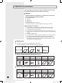
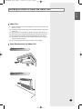
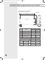
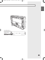
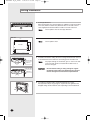
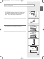
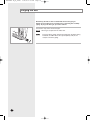
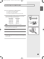
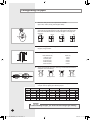
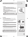
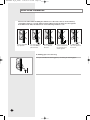
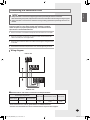
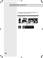
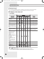
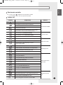
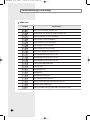
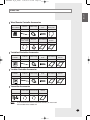
Page 23 INSTALLATION MANUAL System Air Conditioner E§§HNIKA (Cooling and Heating) DEUTSCH PORTUGUÊS ITALIANO FRANÇAIS FH052EAV1 FH070EAV1 ENGLISH 3/24/06 2:53 PM ESPAÑOL FH052EAV IM_E_23980 E S F I P D G DB98-29262A(1) Safety Precautions (Carefully follow the precautions listed below because they are essential to guarantee the safety of the equipment.) WARNING • Always disconnect the air conditioner from the power supply before servicing it or accessing its internal components. • Verify that installation and testing operations are performed by qualified personnel. • Verify that the air conditioner is not installed in an easily accessible area. GENERAL INFORMATION Carefully read the content of this manual before installing the air conditioner and store the manual in a safe place in order to be able to use it as reference after installation. For maximum safety, installers should always carefully read the following warnings. Store the operation and installation manual in a safe location and remember to hand it over to the new owner if the air conditioner is sold or transferred. This manual explains how to install an indoor unit with a split system with two SAMSUNG units. The use of other types of units with different control systems may damage the units and invalidate the warranty. The manufacturer shall not be responsible for damages arising from the use of non compliant units. The manufacturer shall not be responsible for damage originating from unauthorized changes or the improper connection of electric and requirements set forth in the “Operating limits” table, included in the manual, shall immediately invalidate the warranty. The air conditioner should be used only for the applications for which it has been designed: the indoor unit is not suitable to be installed in areas used for laundry. Do not use the units if damaged. If problems occur, switch the unit off and disconnect it from the power supply. In order to prevent electric shocks, fires or injuries, always stop the unit, disable the protection switch and contact SAMSUNG’s technical support if the unit produces smoke, if the power cable is hot or damaged or if the unit is very noisy. Always remember to inspect the unit, electric connections, refrigerant tubes and protections regularly. These operations should be performed by qualified personnel only. The unit contains moving parts, which should always be kept out of the reach of children. Do not attempt to repair, move, alter or reinstall the unit. If performed by unauthorized personnel, these operations may cause electric shocks or fires. Do not place containers with liquids or other objects on the unit. All the materials used for the manufacture and packaging of the air conditioner are recyclable. The packing material and exhaust batteries of the remote control(optional) must be disposed of in accordance with current laws. The air conditioner contains a refrigerant that has to be disposed of as special waste. At the end of its life cycle, the air conditioner must be disposed of in authorized centers or returned to the retailer so that it can be disposed of correctly and safely. INSTALLING THE UNIT IMPORTANT: When installing the unit, always remember to connect first the refrigerant tubes, then the electrical lines. Always disassemble the electric lines before the refrigerant tubes. Upon receipt, inspect the product to verify that it has not been damaged during transport. If the product appears damaged, DO NOT INSTALL it and immediately report the damage to the carrier or retailer (if the installer or the authorized technician has collected the material from the retailer.) After completing the installation, always carry out a functional test and provide the instructions on how to operate the air conditioner to the user. Do not use the air conditioner in environments with hazardous substances or close to equipment that release free flames to avoid the occurrence of fires, explosions or injuries. POWER SUPPLY LINE, FUSE OR CIRCUIT BREAKER Always make sure that the power supply is compliant with current safety standards. Always install the air conditioner in compliance with current local safety standards. Always verify that a suitable grounding connection is available. Verify that the voltage and frequency of the power supply comply with the specifications and that the installed power is sufficient to ensure the operation of any other domestic appliance connected to the same electric lines. Always verify that the cut-off and protection switches are suitably dimensioned. Verify that the air conditioner is connected to the power supply in accordance with the instructions provided in the wiring diagram included in the manual. Always verify that electric connections (cable entry, section of leads, protections…) are compliant with the electric specifications and with the instructions provided in the wiring scheme. Always verify that all connections comply with the standards applicable to the installation of air conditioners. E-2 DH£ª£ª£ªEAV_IM_E_28943-1215.indd 2 2008-1-18 9:41:05 3/24/06 2:53 PM Page 3 ENGLISH FH052EAV IM_E_23980 Contents ■ ■ ■ ■ ■ ■ ■ ■ ■ ■ ■ ■ ■ Preparation for Installation .................................................................................. Deciding on where to Install the indoor unit ........................................................ Ceiling installation ............................................................................................... Floor installation .................................................................................................. Purging the unit ................................................................................................... Connecting the refrigerant pipe ........................................................................... Cutting / Flaring the pipes .................................................................................... Performing leak test & insulation ........................................................................ Drain hose installation ......................................................................................... Connecting the connection cord ......................................................................... Assigning address to indoor unit ......................................................................... Troubleshooting ................................................................................................... Parts list .............................................................................................................. 4 5 8 9 10 11 12 13 14 15 16 18 21 E-3 Preparation for installation When deciding on the location of the air conditioner with the owner, the following restrictions must be taken into account. General Do NOT install the air conditioner in a location where it will come into contact with the following elements: Combustible gases Saline air Machine oil Sulphide gas Special environmental conditions If you must install the unit in such conditions, first consult your dealer. Avoid installing the air conditioner: In areas where it is exposed to direct sunlight. Close to heat sources. In damp areas or locations where it could come into contact with water (for example rooms used for laundry) In areas where curtains and furniture could affect the supply and discharge of air. Without leaving the required minimum space around the unit (as shown in the drawing). In scarcely ventilated areas. On surfaces that are unable to support the weight of the unit without deforming, breaking or causing vibrations during the use of the air conditioner. In a position that does not enable the condensate drainage pipe to be correctly installed (at the end of the installation. It is always essential to check the efficiency of the drainage system.) Accessories The following accessories are supplied with the indoor unit. The type and quantity may differ depending on the specifications. Pattern sheet User’s manual Installation manual Plate Hanger Cable-tie Wireless Remote Controller Accessories (Type A) Wireless remote controller 1 Batteries for STS 2S-2x10 Remote User's manual remote controller tapped screw control holder 2 2 1 1 Installation manual 1 Wireless Remote Controller Accessories (Type B) Wireless remote controller 1 Batteries for M4x12 tapped Remote User's manual remote controller screw control holder 2 2 1 1 Installation manual 1 E-4 DH£ª£ª£ªEAV_IM_E_28943-1215.indd 4 2008-1-18 10:29:33 FH052EAV IM_E_23980 3/24/06 2:53 PM Page 5 ENGLISH Deciding on where to install the indoor unit Indoor Unit ◆ Select a convenient location that permits the air to reach every corner of the area to be cooled. ◆ Pre-plan for easy and short routing of the refrigerant tubing and wiring to the outdoor unit. ◆ There should be no flammable gas, alkaline, substances present in the air. ◆ Avoid location where obstacles preventing good air circulation are present. ◆ Noise prevention should be considered in determining the unit's location. ◆ The structure, where the unit is to be installed should be strong enough to support the weight of the unit. ◆ Do not install the unit where it will be exposed to direct sunlight. Space Requirements for Indoor Unit Ceiling installation 300mm 50mm Floor installation 300mm 300mm E-5 FH052EAV IM_E_23980 3/24/06 2:53 PM Page 6 Deciding on where to install the indoor unit (Continued) Drawing of the indoor unit Unit : mm 1000 197 240 Back side 650 922 45 200 50 No. Description Name 052 1 Liquid pipe connection Ø6.35 Ø6.35 2 Gas pipe connection Ø12.7 Ø15.88 3 Drain pipe connection OD:18; ID:12 4 Drain supply connection - - 5 Air discharge grille - - 6 Air suction grille - - Dimension and Weight Indoor Unit Net Dimension Outdoor Unit Net Weight E-6 070 Indoor Unit Outdoor Unit mm Kg 052 070 1000x650x200 880x638x310 880x798x310 22 50 57 3/24/06 2:53 PM Page 7 ENGLISH FH052EAV IM_E_23980 44 50 Pipe outlet (bottom side) Air intake hole (Ø50) Wiring hole Drain hose outlet E-7 FH052EAV IM_E_23980 3/24/06 2:53 PM Page 8 Ceiling installation 1 300mm or more 300mm or more Select pipe directions. When the directions are selected, drill 3-1/8'' (100mm, for pipe and cables) and 1-3/4'' (40mm, for drain hose) diameter holes on the wall so that it slants slightly downwards toward the outdoor for smooth water flow. Note Unit : mm 2 1000 922 Drill holes for anchor bolts according to the distance and mount them. Use the pattern sheet. 650 240 Note 197 Back side Use the pattern sheet to select pipe directions. 45 50 3 Install the unit onto the ceiling. Be sure to arrange the drain hose so that it is leveled lower than the drain hose connecting port of the indoor unit. Connection pipe Note Drain hose CAUTION Connection pipe Drain hose 4 E-8 For proper drainage of condensate, give a 2° slant to the side of the unit which will be connected with the drain hose as shown in the figure. Ensure that the ceiling is strong enough to support the weight of the indoor unit. Before hanging the unit, test the strength of each attached suspension bolt. If installing on dropped ceiling, install threaded rod onto anchor bolt (expansion bolt) to long enough to suspend the unit right below the dropped ceiling and the install the unit suspending on the threaded rod. FH052EAV IM_E_23980 3/24/06 2:53 PM Page 9 ENGLISH Floor installation 1 Select pipe directions. When the directions are selected, drill 3-1/8'' (100mm, for pipe and cables) and 1-3/4'' (40mm, for drain hose) diameter holes on the wall so that it slants slightly downwards toward the outdoor for smooth water flow. Note 300mm or more Use the pattern sheet to select pipe directions. 300mm or more 3 Install the unit and be sure to arrange the drain hose so that it is leveled lower than the drain hose connecting port of the indoor unit. Drain hose Drain hose Unit : mm 1000 793 101 Install the hanging plate according to the distance and mount it. Back side 650 2 45 50 E-9 FH052EAV IM_E_23980 3/24/06 2:53 PM Page 10 Purging the unit On delivery, the indoor unit is loaded with an inert nitrogen gas. All this gas must therefore be purged before connecting the assembly piping. To purge the inert gas, proceed as follows. Unscrew the caps at the end of each pipe. Result: Note E-10 All inert gas escapes from the indoor unit. To prevent dirt or foreign objects from getting into the pipes during installation, do NOT remove the caps completely until you are ready to connect the piping. FH052EAV IM_E_23980 3/24/06 2:53 PM Page 11 ENGLISH Connecting the refrigerant pipe There are two refrigerant pipes of differing diameters: ◆ A smaller one for the liquid refrigerant ◆ A larger one for the gas refrigerant ◆ The inside of copper pipe must be clean & has no dust. 1 Remove the pinch pipe on the pipes and connect the assembly pipes to each pipe, tightening the nuts, first manually and then with a torque wrench, a spanner applying the following torque. Outer Diameter 6.35 mm (1/4") 9.52 mm (3/8") 12.70 mm (1/2") 15.88 mm (5/8") 19.05 mm (3/4") 22.23 mm (7/8") Note Torque (kgf•cm) 140~170 250~280 380~420 440~480 990~1210 990~1210 If the pipes must be shortened refer to page 12. 2 Must use insulator which is thick enough to cover the refrigerant pipe to protect the condensate water on the outside of pipe falling onto the floor and the efficiency of the unit will be better. 3 Cut off any excess foam insulation. 4 Be sure that there must be no crack or wave on the bended area. 5 It would be necessary to double the insulation thickness(10mm or more) to prevent condensation even on the insulator when if the installed area is warm and humid. Refrigerant oil Torque wrench Spanner Flare nut Union E-11 Cutting/Flaring the pipes 1 Make sure that you have the required tools available. (pipe cutter, reamer, flaring tool and pipe holder). 2 If you wish to shorten the pipes, cut it with a pipe cutter, taking care to ensure that the cut edge remains at a 90° angle with the side of the pipe. Refer to the illustrations below for examples of edges cut correctly and incorrectly. Oblique Rough 3 To prevent any gas from leaking out, remove all burrs at the cut edge of the pipe, using a reamer. 4 Slide a flare nut on to the pipe and modify the flare. Outer diameter (D) 6.35 mm (1/4”) 9.52 mm (3/8”) 12.70 mm (1/2”) 15.88 mm (5/8”) 19.05 mm (3/4”) 5 6 Depth (A) 1.3mm 1.8mm 2.0mm 2.2mm 2.2mm Check that the flaring is correct, referring to the illustrations below for examples of incorrect flaring. Inclined Valve Burr Damaged Surface Cracked Uneven Thickness Align the pipes and tighten the flare nuts first manually and then with a torque wrench, applying the following torque. Flare nut Valve cap Pressure port cap Valve needle Pressure port N•m Wrench(mm) N•m Wrench(mm) N•m Wrench(mm) N•m Wrench(mm) N•m Wrench(mm) 1/4" 3/8" 1/2" 5/8" 3/4" 17 22 26 29 36 18 42 55 65 100 23 23 29 29 38 20 20 40 40 40 18 18 18 18 18 16~18 16~18 16~18 16~18 16~18 Allen(hex.) 5 9 Allen(hex.) 5 9 Allen(hex.) 5 13 Allen(hex.) 5 13 Allen(hex.) 5 13 - 0.34 0.34 0.34 0.34 0.34 CAUTION In case of welding the pipe, you must weld with nitrogen gas blowing. E-12 Gaudi_IM_DB98-28943_E_12.18.07.indd 14 2008-1-26 11:13:17 ENGLISH Performing leak test & insulation Leak test LEAK TEST WITH NITROGEN (before opening valves) In order to detect basic refrigerant leaks, before recreating the vacuum and recirculating the R-410A, it’s responsable of installer to pressurize the whole system with nitrogen (using a cylinder with pressure reducer) at a pressure above 30 bar (gauge). LEAK TEST WITH R-410A (after opening valves) Before opening valves, discharge all the nitrogen into the system and create vacuum. After opening valves check leaks using a leak detector for refrigerant R-410A. CAUTION Discharge all the nitrogen to create a vacuum and charge the system. Insulation Once you have checked that there are no leaks in the system, you can insulate the piping and hose. 1 To avoid condensation problems, place T13.0 or thicker Acrylonitrile Butadien Rubber separately around each refrigerant pipe. Note No gap Always make the seam of pipes face upwards. 2 Wind insulating tape around the pipes and drain hose avoiding to compress the insulation too much. 3 Finish wrapping insulating tape around the rest of the pipes leading to the outdoor unit. 4 The pipes and electrical cables connecting the indoor unit with the outdoor unit must be fixed to the wall with suitable ducts. NBR(T13.0 or thicker) Insulation cover pipe Indoor unit Be sure to overlap the insulation CAUTION All refrigerant connection must be accessible, in order to permit either unit maintenance or removing it completely. CAUTION Must fit tightly against body without any gap. E-13 Gaudi_IM_DB98-28943_E_12.18.07.indd 17 2008-1-26 13:07:54 FH052EAV IM_E_23980 3/24/06 2:53 PM Page 14 Drain hose installation Care must be taken when installing the drain hose for the indoor unit to ensure that any condensation water is correctly drained outside. When passing the drain hose through the hole drilled in the wall, check that none of the following situations occur. 5 cm less The hose must NOT slope upwards. The end of the drain hose must NOT be placed in water. Do NOT bend the hose in different directions. Keep a clearance of at least 5 cm between the end of the hose and the ground. Ditch Do NOT place the end of the drain hose in a hollow. If draining pipe is not too long. It may be extended the draining pipe by connecting as following figure. E-14 Connecting the connection cord ENGLISH CAUTION Always remember to connect the refrigerant pipes before performing the electric connections. When disconnecting the system, always disconnect the electric cables before disconnecting the refrigerant pipes. Always remember to connect the air conditioner to the grounding system before performing the electric connections. The indoor unit is powered by the outdoor unit by means of a H07RN-F connection cable (or a more power model), with insulation in synthetic rubber and jacket in polychloroprene(neoprene), in accordance with the requirements of standard EN 60335-2-40. 1 Remove the screw on the electrical component box and remove the cover plate. 2 Route the connection cord through the side of the indoor unit and connect the cable to terminals; refer to the figure below. 3 Route the other end of the cable to the outdoor unit through the ceiling & the hole on the wall. 4 Reassemble the electrical component box cover, carefully tightening the screw. Wiring diagram Indoor unit 1(L) 2(N) VC VC F1 F2 V1 V2 F1 F3 F4 F2 1(L) 2(N) L N Outdoor unit Between Indoor and Outdoor Connection Cord Specifications Power Supply (Single Phase) Power Supply Max/Min(V) Connection Wire 220-240V~/50Hz ±10% 1.25mm2 Earth Cable Communication Cable Home server Ø 1.6mm,1 wire 0.75~1.25mm2 2 wires 0.75~1.25mm2 2 wires For connection cord, use the grade H07RN-F or H05RN-F materials. Screws on terminal block must not be unscrewed with the torque less than 12 kgf•cm. E-15 Gaudi_IM_DB98-28943_E_12.18.07.indd 19 2008-1-26 13:26:11 FH052EAV IM_E_23980 3/24/06 2:53 PM Page 16 Assigning address to indoor unit 1 Before installing the indoor unit, assign an address to the indoor unit according to the air conditioning system plan. 2 The address of the indoor unit is assigned by adjusting MAIN(SW02) and RMC(SW04) rotary switches. MAIN SW02 E-16 RMC SW04 K1 K2 K3 K4 K5 K6 K7 K8 K9 K10 K11 K12 SW05 SW06 SW07 3/24/06 2:53 PM Page 17 ENGLISH FH052EAV IM_E_23980 3 The MAIN address is for communication between the indoor unit and the outdoor unit. Therefore, you must set it to operate the air conditioner properly. 4 It is required to set the RMC address if you install the centralized controller. 5 If you install optional accessories such as the wired remote controller, centralized controller, etc. see an appropriate installation manual. 6 If an optional accessory is not installed, you do not have to set the RMC address. However, adjust K1 and K2 switches of the SW05 DIP switch to "ON" position in this case. 7 Set the MAIN address by adjusting the rotary switch(SW02) from 0 to 9. Each indoor unit connected to the same outdoor unit must have different address. i. e. If an indoor unit does not have an optional accessory and its MAIN address is "0" MAIN SW02 RMC SW04 K1 K2 K3 K4 K5 K6 K7 K8 K9 K10 K11 K12 SW05 SW06 SW07 E-17 FH052EAV IM_E_23980 3/24/06 2:53 PM Page 18 Troubleshooting Detection of errors ◆ If an error occurs during the operation, an LED flickers and the operation is stopped except the LED. ◆ If you re-operate the air conditioner, it operates normally at first, then detect an error again. LED Display on the indoor unit LED Display LED lamp Remark Error mode Power Reset X Error of the indoor unit sensor X Error of the indoor unit pipe sensor X X X Outdoor sensor error Outdoor cond sensor error Outdoor discharge sensor error Error of the outdoor unit pipe sensor X Communication error (Transmitter, wired remote control) X X EVA sensor secession Cond sensor secession Refrigerant leak 2nd detection Cond high temperature 6th detection Discharge high temperature 6th detection Comp down Freezing detection/Comp stops Freeze prevention control (Errors occur during 6th detection) X X Error of peripherals option set-up X X EEPROM error X X X X X X X Displayed on appropriate indoor unit which is operating X X X Displayed on appropriate indoor unit which is operating X X Displayed on appropriate indoor unit which is operating Displayed on outdoor unit X X X Error of indoor unit: Displayed on the indoor unit regardless of operation X X X X X EEPROM option error ● On Flickering X Off ◆ If you turn off the air conditioner when the LED is flickering, the LED is also turned off. ◆ If you re-operate the air conditioner, it operates normally at first, then detects an error again. E-18 3/24/06 2:53 PM Page 19 ENGLISH FH052EAV IM_E_23980 Wired remote controller ◆ If an error occurs, is displayed on the wired remote controller. ◆ If you would like to see an error code, press the Test button. Outdoor unit Display Explanation Remark Indoor unit Communication Error Indoor/Outdoor unit Communication Time Out Error 60 Packet Over data Communication ERROR Indoor unit is not connected Communication Error between Outdoor Main and Inverter Micom (Occurred after I minute detection in Main and Inverter) Indoor Temp. Sensor (OPEN/SHORT ERROR) Indoor Unit Eva in sensor (OPEN/SHORT ERROR) Indoor Sensor Error Indoor Unit Eva in sensor Separation Outdoor Temp. Sensor Error (OPEN/SHORT ERROR) COND Temp. Sensor Error (OPEN/SHORT ERROR) Outdoor Sensor Error Inverter Compressor Discharge Temp. sensor Error (OPEN/SHORT ERROR) Indoor Float S/W 2nd Detection Outdoor unit-Indoor unit Communication wire Voltage Detection Self Diagnosys Error Outdoor unit Refrigerant Full Leakage (Gas Leak) Outdoor door Fan Error [Inverter] Inverter Comp. Start Failure [Inverter] DC PEAK Error [Inverter] DC LINK Voltage 150V below, 410V Over [Inverter] Comp. Rotation Error [Inverter] Current Sensor Error Outdoor Unit Protection Control Error [Inverter] DC LINK Sensor Error [Inverter] EEPROM READ/WRITE Error [Inverter]Inverter ZEROCROSSING Error Outdoor unit Capacity Setup Option Error Wired Liquid Crystal ↔ Indoor unit Comm. Error Master Wired Liquid Crystal ↔ Slave Liquid Crystal Comm. Error Wired Liquid Crystal COM1/COM2 Cross Error Error of setting option for wired remote controller COM2 Wired Remote Control Error E-19 FH052EAV IM_E_23980 3/24/06 2:53 PM Page 20 Troubleshooting (Continued) Indoor unit Display Explanation Indoor unit communication reception error Communication error between the outdoor and indoor unit Indoor unit temperature sensor (Short/Open) Indoor unit Eva In sensor (Short/Open) Indoor unit Eva Out sensor (Short/Open) Indoor unit Eva In sensor secession Indoor unit Eva Out sensor secession Indoor Eva In and Out sensor secession error Secondary(Electronic)heater sensor 1 error Secondary(Electronic)heater sensor 2 error Secondary(Electronic)heater sensor 3 error Indoor unit float S/W 2nd detection Indoor fan error Mixed operation error EEPROM error EEPROM option setting error Error regarding special sales taxes Electronic heater discharge temperature protection error Electronic heater windless error Indoor unit number setting error(The outdoor unit informs the error) E-20 FH052EAV IM_E_23980 3/24/06 2:53 PM Page 21 ENGLISH Parts list Wired Remote Controller Accessories Wired remote controller Cable-tie Cable clamp 1 2 5 7 1 Wire joint User’s Manual Installation manual 1 1 1 Communication cable of the wired remote controller 1 M4x16 tapped Indoor unit power screw drawing cable Centralized Controller Accessories Centralized controller Cable-tie Cable clamp 1 2 5 M4x16 tapped User’s Manual screw 7 1 Installation manual 1 Function Controller Accessories M4x16 tapped User’s Manual screw Function controller Cable-tie Cable clamp 1 2 6 7 1 Installation manual 1 Transmitter Accessories Transmitter Transmitter power cable Transmitter communication cable Installation manual 1 1 1 1 Note If you would like to install the centralized controller, you must install the transmitter in the outdoor unit. E-21 FH052EAV IM_E_23980 3/24/06 2:53 PM Page 22 ELECTRONICS