1
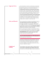
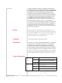
IPSec
User Guide
2120028
Rev 2.2
Important Notice
Safety and Hazards
Due to the nature of wireless communications, transmission and reception of data can never be guaranteed. Data may be delayed, corrupted (i.e., have errors) or be totally lost. Although significant delays or losses of data are rare when wireless devices such as the Sierra Wireless AirLink Product Name are used in a normal manner with a well‐constructed network, the Sierra Wireless AirLink Product Name should not be used in situations where failure to transmit or receive data could result in damage of any kind to the user or any other party, including but not limited to personal injury, death, or loss of property. Sierra Wireless accepts no responsibility for damages of any kind resulting from delays or errors in data transmitted or received using the Sierra Wireless AirLink Product Name, or for failure of the Sierra Wireless AirLink Product Name to transmit or receive such data.
Do not operate the Sierra Wireless AirLink Product Name in areas where blasting is in progress, where explosive atmospheres may be present, near medical equipment, near life support equipment, or any equipment which may be susceptible to any form of radio interference. In such areas, the Sierra Wireless AirLink Product Name MUST BE POWERED OFF. The Sierra Wireless AirLink Product Name can transmit signals that could interfere with this equipment.
Do not operate the Sierra Wireless AirLink Product Name in any aircraft, whether the aircraft is on the ground or in flight. In aircraft, the Sierra Wireless AirLink Product Name MUST BE POWERED OFF. When operating, the Sierra Wireless AirLink Product Name can transmit signals that could interfere with various onboard systems.
Note: Some airlines may permit the use of cellular phones while the
aircraft is on the ground and the door is open. Sierra Wireless AirLink
Product Name may be used at this time.
The driver or operator of any vehicle should not operate the Sierra Wireless AirLink Product Name while in control of a vehicle. Doing so will detract from the driver or operatorʹs control and operation of that vehicle. In some states and provinces, operating such communications devices while in control of a vehicle is an offence.
Limitation of
Liability
Rev 2.2 Jun.11
The information in this manual is subject to change without notice and does not represent a commitment on the part of Sierra Wireless. SIERRA WIRELESS AND ITS AFFILIATES SPECIFICALLY DISCLAIM LIABILITY FOR ANY AND ALL i
DIRECT, INDIRECT, SPECIAL, GENERAL, INCIDENTAL, CONSEQUENTIAL, PUNITIVE OR EXEMPLARY DAMAGES INCLUDING, BUT NOT LIMITED TO, LOSS OF PROFITS OR REVENUE OR ANTICIPATED PROFITS OR REVENUE ARISING OUT OF THE USE OR INABILITY TO USE ANY SIERRA WIRELESS PRODUCT, EVEN IF SIERRA WIRELESS AND/OR ITS AFFILIATES HAS BEEN ADVISED OF THE POSSIBILITY OF SUCH DAMAGES OR THEY ARE FORESEEABLE OR FOR CLAIMS BY ANY THIRD PARTY.
Notwithstanding the foregoing, in no event shall Sierra Wireless and/or its affiliates aggregate liability arising under or in connection with the Sierra Wireless product, regardless of the number of events, occurrences, or claims giving rise to liability, be in excess of the price paid by the purchaser for the Sierra Wireless product.
Patents
Copyright
Trademarks
This product may contain technology developed by or for Sierra Wireless Inc. This product includes technology licensed from QUALCOMM® 3G. This product is manufactured or sold by Sierra Wireless Inc. or its affiliates under one or more patents licensed from InterDigital Group.
© 2011 Sierra Wireless. All rights reserved.
AirCard® and “Heart of the Wireless Machine®” are registered trademarks of Sierra Wireless. Watcher® is a trademark of Sierra Wireless, registered in the European Community. AirLink™ and AceWare™ are trademarks of Sierra Wireless.
Sierra Wireless, the Sierra Wireless logo, the red wave design, and the red‐tipped antenna are trademarks of Sierra Wireless.
Windows® is a registered trademark of Microsoft Corporation.
Other trademarks are the property of the respective owners.
Contact Information
Support Desk:
Phone: 1-877-231-1144
Hours: 5:00 AM to 5:00 PM Pacific Time,
Monday to Friday, except US Holidays
E-mail: [email protected]
Sales Desk:
Phone: 1-510-624-4200
1-604-232-1488
Hours: 8:00 AM to 5:00 PM Pacific Time
E-mail: [email protected]
Rev 2.2 Jun.11
ii
Post: Sierra Wireless America
39677 Eureka Drive
Newark, CA
USA
94560
Sierra Wireless
13811 Wireless Way
Richmond, BC
Canada
V6V 3A4
Fax: 1-510-624-4299
1-604-231-1109
Web: www.sierrawireless.com
Consult our website for up‐to‐date product descriptions, documentation, application notes, firmware upgrades, trouble‐
shooting tips, and press releases:
www.sierrawireless.com
Revision History
Revision
number
Release
date
Changes
1.x
Q2: 2008
IPSec User Guide documentation created.
2.x
Q2:2008
IPSec User Guide documentation revised and updated.
Rev 2.2 Jun.11
iii
Contents
Introducing IPSec . . . . . . . . . . . . . . . . . . . . . . . . . . . . . . . . . . . . . . . . . . . . . . . . . . . . . . 1
Overview. . . . . . . . . . . . . . . . . . . . . . . . . . . . . . . . . . . . . . . . . . . . . . . . . . . . . . . . . . . . 1
Key Features of IPSec VPN . . . . . . . . . . . . . . . . . . . . . . . . . . . . . . . . . . . . . . . . . . 2
Scenarios . . . . . . . . . . . . . . . . . . . . . . . . . . . . . . . . . . . . . . . . . . . . . . . . . . . . . . . . . . . . 3
Remote Access Scenarios . . . . . . . . . . . . . . . . . . . . . . . . . . . . . . . . . . . . . . . . . . . 3
Installation and Configuration . . . . . . . . . . . . . . . . . . . . . . . . . . . . . . . . . . . . . . . . . . . . 6
Set-Up . . . . . . . . . . . . . . . . . . . . . . . . . . . . . . . . . . . . . . . . . . . . . . . . . . . . . . . . . . . . . . 7
Modem Configuration Requirements . . . . . . . . . . . . . . . . . . . . . . . . . . . . . . . . . . 7
Installation . . . . . . . . . . . . . . . . . . . . . . . . . . . . . . . . . . . . . . . . . . . . . . . . . . . . . . . . . . 8
AT*RESETCFG . . . . . . . . . . . . . . . . . . . . . . . . . . . . . . . . . . . . . . . . . . . . . . . . 8
Configuration Settings . . . . . . . . . . . . . . . . . . . . . . . . . . . . . . . . . . . . . . . . . . . . . . . . . 8
HTTP Server . . . . . . . . . . . . . . . . . . . . . . . . . . . . . . . . . . . . . . . . . . . . . . . . . . . . 12
Application Server . . . . . . . . . . . . . . . . . . . . . . . . . . . . . . . . . . . . . . . . . . . . . . . . 13
Network behind the modem . . . . . . . . . . . . . . . . . . . . . . . . . . . . . . . . . . . . . . . . . 15
Sample Configuration File . . . . . . . . . . . . . . . . . . . . . . . . . . . . . . . . . . . . . . . . . . . . . . . 18
VPN Configuration file . . . . . . . . . . . . . . . . . . . . . . . . . . . . . . . . . . . . . . . . . . . . 18
Static IP. . . . . . . . . . . . . . . . . . . . . . . . . . . . . . . . . . . . . . . . . . . . . . . . . . . . . . 18
Dynamic IP . . . . . . . . . . . . . . . . . . . . . . . . . . . . . . . . . . . . . . . . . . . . . . . . . . . 21
IPsec Architecture. . . . . . . . . . . . . . . . . . . . . . . . . . . . . . . . . . . . . . . . . . . . . . . . . . . . . . 24
Standards of the M2M IPSec Support . . . . . . . . . . . . . . . . . . . . . . . . . . . . . 24
Security Algorithms: . . . . . . . . . . . . . . . . . . . . . . . . . . . . . . . . . . . . . . . . . . . 24
Reference Material . . . . . . . . . . . . . . . . . . . . . . . . . . . . . . . . . . . . . . . . . . . . . . . . . . . 25
Rev 2.2 Jun.11
1
IPsec User Guide
2
2120028
1: Introducing IPSec
• Overview
• Scenarios
1
IP protocol that drives the Internet is inherently insecure. Internet Protocol Security (IPSec), which is a standards‐based protocol, secures communications of IP packets over public networks. Organizations are striving to protect their communication channels from unauthorized viewing and enforcing authenti‐
cation of the entities at the other side of the channel.
Unauthorized access to the sensitive data can be avoided by using IPSec. By applying security at the IP layer in the OSI model, communications can be protected. In this manner the upper layers in the OSI model can leverage the security services provided at the IP layer. Sierra Wireless AirLink™ has added IPSec, as a latest addition to the list of features, in all the ALEOS‐powered AirLink X and XT platforms of devices. Overview
IPSec is a common network layer security control and is used to create a virtual private network (VPN). The advantages of the IPSec feature includes:
•
Data Protection: Data Content Confidentiality allows users to protect their data from any unauthorized view, because the data is encrypted (encryption algorithms are used).
•
Access Control: Access Control implies a security service that prevents unauthorized use of a Security Gateway, a network behind a gateway or bandwidth on that network.
•
Data Origin Authentication: Data Origin Authentication verifies the actual sender, thus eliminating the possibility of forging the actual sender’s identification by a third‐
party.
•
Data Integrity: Data Integrity Authentication allows both ends of the communication channel to confirm that the original data sent has been received as transmitted, without being tampered with in transit. This is achieved by using authentication algorithms and their outputs.
The IPSec architecture model includes the Sierra Wireless AirLink modem as a remote gateway at one end communi‐
cating, through a VPN tunnel, with a VPN gateway at the Rev 2.2 Jun.11
1
IPsec User Guide
other end. The remote gateway is connected to a Remote network and the VPN is connected to the Local network. The communication of data is secure through the IPSec protocols.
Figure 1-1: IPSec Architecture
Key Features of IPSec VPN
IPsec is compatible with a wide range of applications: •
Provides enhanced data security for all applications connected through a compatible Airlink gateway
•
No additional installation required •
Simple wizard‐based setup •
Remote management, control and configuration via AceWare tools and utilities
•
Secure two‐way communication channel with data encryption
•
Can be downloaded, configured and installed over‐the‐air for currently deployed AirLink Raven X, PinPoint X and Raven XT device
Sections in this document, that provide further information about IPSec, are: 2
1.
User scenarios with graphic illustration of the IPSec feature. 2.
VPN configuration settings and VPN parameters. 3.
IPsec configuration settings. It is assumed that audience has knowledge of AceManager. 4.
Testing and basic troubleshooting.
2120028
Introducing IPSec
Scenarios
Sierra Wireless AirLink modems with IPSec are designed to support the gateway‐to‐gateway security model.
IPsec is the most general security model, in that it allows either side to initiate a VPN session. Some user scenario’s are discussed in this section. In these examples, the term “VPN tunnel” is used to indicate a secure IPSec connection.
Remote Access Scenarios
1.
This scenario shows three remote access activities:
a.
AVL Application Server (one way transmission of secure data): AirLink modem has GPS capability (PinPoint model). The modem has set up a VPN tunnel with a corporate VPN box and is configured to send GPS location data to the corporate network.
Figure 1-2: AVL Application Server scenario
b. Corporate Email Server (two way transmission of secure data): AirLink modem is connected to a laptop. The modem setup has a VPN tunnel with the corporate VPN box. Through the modem, the laptop can securely access the corporate email server.
Rev 2.2 Jun.11
3
IPsec User Guide
Figure 1-3: Corporate Email Server scenario
c.
Google (two way transmission of insecure data): The laptop user wants to access Google. The Google access can be performed while the corporate VPN tunnel is active.
Figure 1-4: Web Server scenario
d. Pass‐through (two way transmission of secure data): The AirLink modem has regular data connection with the laptop (VPN Client) and the VPN gateway.
4
2120028
Introducing IPSec
Figure 1-5: Pass through mode
The next chapter walks you through the installation and configuration steps of establishing an IPSec set‐up on your modem to connect to the test servers at Sierra Wireless. You can follow the same process for connecting to your own VPN gateway.
Rev 2.2 Jun.11
5
IPsec User Guide
6
2120028
2: Installation and Configuration
• Set-Up
• Installation
• Configuration Settings
Note: Factory default settings
allow you to connect to Sierra
Wireless test equipment.
2
This chapter covers installation and configuration steps (Sierra Wireless test set‐up), to use the IPSec feature.
The illustration below shows the user being connected to the Sierra Wireless test environment set up. The user laptop connected to an AirLink modem, communicates with the web server over the internet and through the Sierra Wireless VPN Gateway (Cisco and Netgear).
Figure 2-1: User set up
Once the tunnel is established and you are connected to the web server, the web browser displays connectivity to the Sierra Wireless IPSec test server.
Figure 2-2: Connection to the web browser
Rev 2.2 Jun.11
6
IPsec User Guide
Set-Up
IPSec has a wide variety of user configuration options. When IPSec is enabled, it must be done for the purpose of creating a VPN tunnel with a corporate VPN box. In order for the Sierra Wireless AirLink modem to communicate with the VPN box, the modem must be configured to support at least one of the security policies of the VPN box. Hence, the VPN box security configuration must be available as a reference before config‐
uring the AirLink modem for IPSec.
The installation steps are as follows:
1.
For Static IP: Using your modem’s static IP, configure your Cisco VPN to allow a tunnel to be established with your modem’s IP address.
2.
For Dynamic IP: Configure your Cisco VPN to allow a tunnel to be established dynamically with your modem’s current IP address
3.
Connect your PC to the modem, and launch AceManager. Navigate to the IPSec configuration screen. Select the parameters that correspond to your Cisco configuration, and press the Write button on the top. Close AceManager.
4.
Open a browser or other application and attempt to communicate with your enterprise network.
Modem Configuration Requirements
The modem should be provisioned and capable of passing traffic over the carrier network. If the modem is not provi‐
sioned, you will need to activate it in order to configure the account parameters. The Quick Start Guide for your modem will lead you through the steps to activate or configure your modem. You can access the Quick Start Guides on the support page for your modem. For 1x or EV‐DO modems, you will also need a Setup Wizard, which is available on the support page as well. The modem can have a static or dynamic IP address, which can be obtained from AceManager. The IP address is listed as the first displayed entry on the Status page.
The modem firmware version should be 3.3 or higher. If the modem firmware is 3.2 or lower, you will need to upgrade the modem firmware. Please contact your Sierra Wireless sales engineer for the appropriate firmware update utility.
7
2120028
IPsec User Guide
Installation
Please uninstall any previous versions of AceManager that had been installed on your PC, prior to installing the latest version of AceManager. AceManager is available for free from Sierra Wireless AirLink and can be downloaded from http://www.sierrawireless.com/
support/AirLink/Wireless_Ace.aspx.
Once this new version of AceManager and the new firmware is installed on your PC, please perform a factory default reset of the modem using a AT command:
AT*RESETCFG
This command will reset the modem with factory defaults and once the modem comes back up, please connect the modem with AceManager. Configuration Settings
Once the AceManager application is installed, you can run it from your Start menu or from the icon on the desktop.
1. Start AceManager
Start > All Programs >AirLink Communications > AceManager
8
2120028
IPsec User Guide
Figure 2-3: IPSec Pane in AceManager
2. Click on IPSec
The desired group tab will show respective parameters and details on the right side of the pane. Clicking on IPSec will display list of parameters with default values and user config‐
urable input fields (New Value).
Table 2-1: Configuration Parameters in AceManager
Name
9
Default Value
Description
IPSec Interface
0
Select 1-Modem-OTA.
Choose “0” fir disabling IPSec.
Choose “1” for enabling IPSec.
Choose “4” when you use
ethernet for testing IPSec.
IPSec Status
Disconnected
Shows the status of IPSec.
2120028
IPsec User Guide
Table 2-1: Configuration Parameters in AceManager
Name
10
Default Value
Description
IPSec Gateway
64.163.70.30
Fill in the IPSec of the VPN
concentrator.
Pre-shared Key 1
SierraWireless
8 to 31 case sensitive ASCII
characters
Negotiation Mode
1
The choices in drop down options
are main or aggressive.
IKE Encryption Algorithm
7
You can choose other options
like, Blowfish, 3 DES, Cast 128
and AES.
3DES or AES can be used for
stronger encryption.
IKE Authentication Algorithm
2
Three different authentication
algorithms are among the dropdown choices.
1-MD5 is for minimal security and
2-SH-1 is higher security. 5-SHA256 is also an option.
IKE Key Group
2
Different Key Groups are, 1-DH1,
2-DH2 and 3-DH3.
IKE SA Life Time
7200 (seconds)
Enter the lifetime of VPN of how
long it is valid. “0” reflects no
expiry.
Local Address Type
1
Choose from drop-down menu.
• “1” indicates Modem Public
IP. It is the IP of the device
behind the modem, when the
modem is in public mode.
•
“2” indicates Host Private
Subnet of the device behind
the modem on the same
subnet, when the modem is
in private mode.
•
“5” indicates Single Address.
•
“17” indicates Subnet
Address.
Local Address
0.0.0.0
Local Address of the device
connected to the modem.
Local Address - end or mask
0.0.0.0
Subnet address with the Subnet
Mask
Remote Address Type
17
Network behind the Concentrator.
2120028
IPsec User Guide
Table 2-1: Configuration Parameters in AceManager
Name
11
Default Value
Description
Remote Address
10.11.12.0
Address of the remote device.
Choose from two options: 5Single Address and 17-Subnet
Address.
Remote Address - end or mask
255.255.255.0
Subnet address with the Subnet
Mask.
IPSec Encryption Algorithm
3
You can choose other options
like, Blowfish, 3 DES, Cast 128
and AES. The option “0” indicates
that IPSec encryption may not be
used.
3DES or AES can be used for
stronger encryption.
IPSec Authentication Algorithm
2
Three different authentication
algorithms are among the dropdown choices.
1-MD5 is for minimal security and
2-SH-1 is higher security. 5-SHA256 is also an option. “0” is also
an option for not applying IPSec
aunthentication algorithm.
IPSec Key Group
2
Different Key Groups are, 1-DH1,
2-DH2 and 5-DH5.
DH5 denotes highest security
IPSec SA Life Time
7200 (seconds)
This indicates how often the
modem renegotiates the IKE SA.
While the renegotiation happens
the VPN tunnel gets
disconnected temporarily.
Incoming Out of Band
0
Enable (1) or Disable (0) access
to modem remotely from
machines that are not part of the
IPSec network.
Outgoing Aleos Out of Band
1
Enable (1) or Disable (0) sending
of ALEOS traffic over the IPSec
tunnel to a remote location.
This option allows ALEOS
generated data (E.g. RAP) to be
sent outside the IPSec tunnel.
Outgoing Host Out of Band
0
Enable (1) or Disable (0) access
to resources outside the IPSec
network. (e.g. Enable access to
sites like www.google.com over
non IPSec channel).
2120028
IPsec User Guide
To confirm a successful connection, the following tests can be run:
•
Connect a PC to the modem and attempt to ping the IP address 10.11.12.13. The tunnel might take some time to be established. However once the tunnel is established you will receive responses to your ping.
•
Once the ability to ping the private address has been estab‐
lished, please try opening a browser and pointing it to http://10.11.12.13.
Once these two tests pass, a baseline for the IPSec configu‐
ration in the modem has been established.
You can now begin to make the IPSec configuration changes to get the modem connecting to your own IPSec gateway.
Different scenario use cases and their configuration steps in Ace Manager, to establish the IPSec tunnel, are addressed in the following sections.
HTTP Server
A PC connected to a Sierra Wireless AirLink Modem uses web browser to view an HTTP server behind the IPsec Gateway.
The Configuration steps are:
1.
In AceManager, click on the IPSec tab. Please refer to Figure 2‐3.
2.
Configure the IPSec Interface parameter as “1”, to enable IPSec. Once IPSec is enabled, the factory default settings should be restored. Table 2‐1 lists all the IPSec parameter default values. The required fields for IPSec to be estab‐
lished are:
a.
IPSec Gateway
b. Pre-shared Key 1
c.
IKE Encryption Algorithm
d. IKE Authorization Algorithm
e.
IKE Key Group
f.
IKE SA Life Time
g.
Remote Address
h. IPSec Encryption Algorithm
i.
IPSec Authentication Algorithm
j.
IPSec Key Group
k. IPSec SA Life Time
l.
12
Incoming Out of Band: If you want mobile termination
2120028
IPsec User Guide
m. Outgoing Host Out of Band: To access internet by bypassing the IPSec tunnel, you can set this parameter as “1”. Note: In Chapter 1, Remote Access Scenarios section includes the
Google web server scenario, where the outgoing Host Out of Band
can be set to 1 to access internet outside the IPSec tunnel.
3.
Click on Write, in the top bar.
4.
Click on Reset, to reset the modem. 5.
IPSec status displays as “Connected”.
Once the tunnel comes up, ping the web browser. The web browser should be able to reach the server. An example of a web browser screenshot, after the tunnel establishes, is provided.
Figure 2-4: Web Browser
Application Server
A Sierra Wireless AirLink Modem sends AVL Application Server data through the tunnel for the Report Server that is behind the IPsec Gateway.
The Configuration steps are:
1.
13
In AceManager, click on the PinPoint tab and ensure values that correspond to Figure 2‐5.
2120028
IPsec User Guide
Figure 2-5: PinPoint Configuration
2.
Provide the Server IP Address on the right‐hand side pane. 3.
Enter the Report Interval time.
4.
Configure the IPSec Interface parameter as “1”, to enable IPSec. Once IPSec is enabled, the factory default settings should be restored. Table 2‐1 lists all the IPSec parameter default values. The required fields for IPSec to be estab‐
lished are:
a.
IPSec Gateway
b. Pre-shared Key 1
c.
IKE Encryption Algorithm
d. IKE Authorization Algorithm
e.
IKE Key Group
f.
IKE SA Life Time
g.
Remote Address
h. IPSec Encryption Algorithm
i.
IPSec Authentication Algorithm
j.
IPSec Key Group
k. IPSec SA Life Time
l.
Incoming Out of Band: If you want mobile termination
m. Outgoing Host Out of Band: To access internet outside the tunnel, from the modem.
14
5.
Click on Write.
6.
Click on Reset, to reset the modem.
2120028
IPsec User Guide
An AVL Application server modem report notification image is provided as an example.
Figure 2-6: Application Server Tunnel
7.
Once the tunnel comes up, check AVL Application server for the update. An example of a log of the modem, sending data through the tunnel is provided.
Figure 2-7: Log sending data
Network behind the modem
You can have multiple machines (For example., PC1 and PC2) behind the modem on the same LAN.
The Configuration steps are:
15
1.
In AceManager, click on IPSec option.
2.
Go to Local address type and set it to “2” (Host Private Subnet).
2120028
Installation and Configuration
Figure 2-8: Host Private Subnet
3.
Click on PPP ethernet. Set the modem to private mode.
Figure 2-9: PPP Ethernet configuration
Rev 2.2 Jun.11
16
IPsec User Guide
4.
Configure the IPSec Interface parameter as “1”, to enable IPSec. Once IPSec is enabled, the factory default settings should be restored. Table 2‐1 lists all the IPSec parameter default values. The required fields for IPSec to be estab‐
lished are:
a.
IPSec Gateway
b. Pre-shared Key 1
c.
IKE Encryption Algorithm
d. IKE Authorization Algorithm
e.
IKE Key Group
f.
IKE SA Life Time
g.
Remote Address
h. IPSec Encryption Algorithm
i.
IPSec Authentication Algorithm
j.
IPSec Key Group
k. IPSec SA Life Time
l.
Incoming Out of Band: If you want mobile termination
m. Outgoing Host Out of Band: To access internet outside the tunnel, from the modem.
5.
Make sure the static IP address of PC2 is on the same subnet as the modem’s host private IP. PC1 picks up the dynamic IP address and PC2 should be set to a static IP address.
6.
Click on Reset, to reset the modem.
The IPSec tunnel is set up.
Now, you should be able to reach the other side of the server from PC1 an/or PC2. Both the machines (PC1 and PC2)can be communicated with, from the server through the IPSec tunnel. The modem is reachable from the remote server as well.
17
2120028
A: Sample Configuration File
A
VPN Configuration file
Two examples of Static IP and Dynamic IP are provided in the following sections, respectively. Static IP
Example IPSec Configuration for Cisco 1841 Router
1841_ppx2#show run
Building configuration...
Current configuration : 2202 bytes
!
version 12.4
service timestamps debug datetime msec
service timestamps log datetime msec
no service password-encryption
!
hostname 1841_ppx2
!
boot-start-marker
boot-end-marker
!
!
no aaa new-model
!
resource policy
!
mmi polling-interval 60
no mmi auto-configure
no mmi pvc
mmi snmp-timeout 180
ip subnet-zero
ip cef
!
!
Rev 2.2 Jun.11
18
IPsec User Guide
username progent privilege 15 password 0 progent
!
crypto isakmp policy 2
encr 3des
authentication pre-share
group 2
lifetime 28000
crypto isakmp key 6 key4567890123477 address 166.213.198.10
crypto isakmp key test address 70.2.190.17
!
!
crypto ipsec transform-set AES-SHA esp-aes esp-sha-hmac
crypto ipsec transform-set 3DES-SHA esp-3des esp-sha-hmac
!
crypto map IPSEC 30 ipsec-isakmp
set peer 166.213.198.10
set security-association lifetime seconds 28000
set transform-set 3DES-SHA
set pfs group2
match address 101
crypto map IPSEC 40 ipsec-isakmp
set peer 70.2.190.17
set security-association lifetime seconds 28000
set transform-set 3DES-SHA
set pfs group2
match address 102
!
!
!
interface FastEthernet0/0
ip address 64.163.70.102 255.255.255.0
ip nat outside
ip virtual-reassembly
duplex auto
speed 10
crypto map IPSEC
!
19
Sample Configuration File
interface FastEthernet0/1
ip address 192.168.2.1 255.255.255.0
ip nat inside
ip virtual-reassembly
duplex auto
speed auto
!
ip classless
ip route 0.0.0.0 0.0.0.0 64.163.70.1
ip route 192.168.3.0 255.255.255.0 70.2.190.17
ip route 192.168.13.0 255.255.255.0 166.213.198.10
!
no ip http server
no ip http secure-server
ip nat pool nat 64.163.70.102 64.163.70.102 netmask
255.255.255.252
ip nat inside source list 110 pool nat overload
!
access-list 101 permit ip 192.168.2.0 0.0.0.255 host 166.213.198.10
access-list 101 permit ip 192.168.2.0 0.0.0.255 host 192.168.13.100
access-list 102 permit ip 192.168.2.0 0.0.0.255 192.168.3.0 0.0.0.255
access-list 110 deny ip 192.168.2.0 0.0.0.255 192.168.3.0 0.0.0.255
access-list 110 deny ip 192.168.2.0 0.0.0.255 192.168.13.0
0.0.0.255
access-list 110 deny ip 192.168.2.0 0.0.0.255 host 166.213.198.10
access-list 110 permit ip 192.168.2.0 0.0.0.255 any
!
!
control-plane
!
!
line con 0
line aux 0
line vty 0 4
login local
transport input all
!
end
Rev 2.2 Jun.11
20
IPsec User Guide
Dynamic IP
1841b_dynamic#
1841b_dynamic#sh run
Building configuration...
Current configuration : 1479 bytes
!
version 12.4
service timestamps debug datetime msec
service timestamps log datetime msec
no service password-encryption
!
hostname 1841b_dynamic
!
boot-start-marker
boot-end-marker
!
no logging console
!
no aaa new-model
!
resource policy
!
mmi polling-interval 60
no mmi auto-configure
no mmi pvc
mmi snmp-timeout 180
ip subnet-zero
ip cef
!
!
!
!
!
username sw privilege 15 password 0 sw
!
!
21
Sample Configuration File
!
crypto isakmp policy 100
encr 3des
authentication pre-share
group 2
lifetime 28000
crypto isakmp key 6 key4567890123477 address 0.0.0.0 0.0.0.0 noxauth
!
!
crypto ipsec transform-set 3DES-SHA esp-3des esp-sha-hmac
!
crypto dynamic-map MODEM-DYN-MAP 1000
set security-association lifetime seconds 28000
set transform-set 3DES-SHA
set pfs group2
match address 101
!
!
crypto map IPSEC 65535 ipsec-isakmp dynamic MODEM-DYN-MAP
!
!
!
interface FastEthernet0/0
ip address 64.163.70.104 255.255.255.0
ip virtual-reassembly
speed 100
full-duplex
crypto map IPSEC
!
interface FastEthernet0/1
ip address 192.168.4.1 255.255.255.0
ip virtual-reassembly
duplex auto
speed auto
!
ip classless
Rev 2.2 Jun.11
22
IPsec User Guide
ip route 0.0.0.0 0.0.0.0 64.163.70.1
!
ip http server
no ip http secure-server
ip nat pool nat 64.163.70.104 64.163.70.104 netmask
255.255.255.252
ip nat inside source list 110 pool nat overload
!
access-list 101 permit ip 192.168.4.0 0.0.0.255 any
access-list 101 permit ip any 192.168.4.0 0.0.0.255
!
!
control-plane
!
!
line con 0
line aux 0
line vty 0 4
login
!
end
23
B: IPsec Architecture
B
Standards of the M2M IPSec Support
Sierra Wireless M2M IPSec supports the following standards: •
RFC 1829 – “The ESP DES‐CBC Transform” •
RFC 2401 – “Security Architecture for the Internet Protocol” •
RFC 2403 – “The Use of HMAC‐MD5‐96 within ESP and AH” •
RFC 2404 – “The Use of HMAC‐SHA‐1‐96 within ESP and AH” •
RFC 2405 – “The ESP DES‐CBC Cipher Algorithm With Explicit IV” •
RFC 2406 – “IP Encapsulating Security Payload (ESP)” •
RFC 2410 – “The NULL Encryption Algorithm and Its Use With IPSec” •
RFC 2451 – “The ESP CBC‐Mode Cipher Algorithms” •
RFC 3602 – “The AES‐CBC Cipher Algorithm and Its Use with IPSec” (future enhancement) Security Algorithms:
1.
Internet Key Exchange (IKE) a.
Authentication for IKE Messages (Hashing Algorithms) · MD5 · SHA1 b. Exchange Modes Supported in Phase 1 and Phase 2 of IKE · Main Mode · Aggressive Mode · Quick Mode · Informational Mode c. Authentication Methods (used in Phase 1) · Authentication using pre‐shared keys · Authentication using RSA signatures d. Oakley Groups: used during Phase 1 to calculate keys for the IKE Security Association · First Oakley Group (MODP 768) · Second Oakley Group (MODP 1024) · Fifth Oakley Group (MODP 1536) · MODP 2048 (available, but not currently supported) · MODP 3072 (available, but not currently supported) Rev 2.2 Jun.11
24
IPsec User Guide
· MODP 4096 (available, but not currently supported) · MODP 6144 (available, but not currently supported) · MODP 8192 (available, but not currently supported) 2.
IP Security (IPSec) a. IPSec Protocols · Encapsulating Security Protocol (ESP) b. Operational Modes · Tunnel Mode c. Cipher or Encryption Algorithms · DES · CAST128 · Blowfish · AES (future) · NULL encryption algorithm d. Usage Options – Modem can support unencrypted traffic, and one option below for encryption: · No authentication or encryption · Authentication only · Encryption only · Authentication and Encryption Reference Material
National Institute of Standards and Technology. Guide to IPsec VPNs. Retrieved January 7, 2008, from http://csrc.nist.gov/
publications/nistpubs/800‐77/sp800‐77.pdf for IPsec White Paper resource.
5 Articles on IPsec by Cisco: http://www.ciscopress.com/
authors/bio.asp?a=523e2313‐3b15‐4e8e‐b051‐
c71d7fd6528d&rl=1
IPsec setup on Linux (includes useful examples): http://
lartc.org/howto/lartc.ipsec.html
25