1
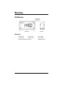
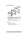
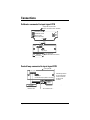
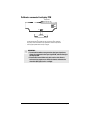
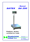
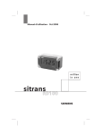
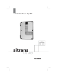
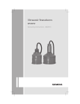
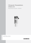
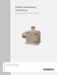
Remote Displays
SITRANS RD100
Operating Instructions 01/2011
SITRANS
Safety Guidelines: Warning notices must be observed to ensure personal safety as well as that of
others, and to protect the product and the connected equipment. These warning notices are
accompanied by a clarification of the level of caution to be observed.
Qualified Personnel: This device/system may only be set up and operated in conjunction with this
manual. Qualified personnel are only authorized to install and operate this equipment in accordance with
established safety practices and standards.
Unit Repair and Excluded Liability:
•
•
•
•
The user is responsible for all changes and repairs made to the device by the user or the user’s
agent.
All new components are to be provided by Siemens Milltronics Process Instruments.
Restrict repair to faulty components only.
Do not reuse faulty components.
Warning: Cardboard shipping package provides limited humidity and moisture protection. This product
can only function properly and safely if it is correctly transported, stored, installed, set up, operated, and
maintained.
This product is intended for use in industrial areas. Operation of this equipment in a residential area
may cause interference to several frequency based communications.
Note: Always use product in accordance with specifications.
Copyright Siemens AG 2011. All Rights
Reserved
This document is available in bound version and in
electronic version. We encourage users to purchase
authorized bound manuals, or to view electronic
versions as designed and authored by Siemens
Milltronics Process Instruments. Siemens Milltronics
Process Instruments will not be responsible for the
contents of partial or whole reproductions of either
bound or electronic versions.
Disclaimer of Liability
While we have verified the contents of this
manual for agreement with the
instrumentation described, variations remain
possible. Thus we cannot guarantee full
agreement. The contents of this manual are
regularly reviewed and corrections are
included in subsequent editions. We welcome
all suggestions for improvement.
Technical data subject to change.
MILLTRONICS®is a registered trademark of Siemens Milltronics Process Instruments.
Contact SMPI Technical Publications
at the following address:
Technical Publications
Siemens AG
Siemens Milltronics Process Instruments
1954 Technology Drive, P.O. Box 4225
Peterborough, Ontario, Canada, K9J 7B1
Email: [email protected]
•
•
European Authorized Representative
Siemens AG
Industry Sector
76181 Karlsruhe
Deutschland
For a selection of Siemens Milltronics level measurement manuals, go to:
www. siemens.com/processautomation. Under Process Instrumentation, select Level
Measurement and then go to the manual archive listed under the product family.
For a selection of Siemens Milltronics weighing manuals, go to:
www. siemens.com/processautomation. Under Weighing Technology, select Continuous
Weighing Systems and then go to the manual archive listed under the product family.
© Siemens AG 2011
SITRANS RD100 Loop Powered Meter
SITRANS RD100
SITRANS RD100 is a 2-wire loop powered, NEMA 4X enclosed remote digital display for
process instrumentation.
This digital meter is easy to use with a display of 3.5 digits, 1" (2.54 cm) high. It accepts 4 to
20 mA input and operates from -40 to +80 °C (-40 to +176 °F).
SITRANS RD100 is CSA and FM Approved.
Safety Notes
Special attention must be paid to warnings and notes highlighted from the rest of the text
by grey boxes.
WARNING: means that failure to observe the necessary precautions
can result in death, serious injury, and/or considerable material
damage.
CAUTION: means that failure to observe the necessary precautions can
result in considerable material damage.
Note: means important information about the product or that part of the operating
manual.
The Manual
This manual provides specifications and instructions for the operation of SITRANS RD100
Remote Display. The manual is designed to help you get the most out of your Remote
Display, and it provides information on the following:
•
•
•
•
Meter specifications
Wiring diagrams
Installation requirements
Setup instructions
If you have any questions, comments, or suggestions about the manual content, please
email us at [email protected]. For the complete library of Siemens Milltronics
manuals, go to www.siemens.com/processautomation.
7ML19985JU01
SITRANS RD100 – INSTRUCTION MANUAL
Page 1
Specifications
Note: Except where noted, all specifications apply to operation at +25 °C (+77 °F).
Display
• 1.0 " (25.4 mm) high LCD, numeric display range from -1000 to 1999
Enclosure
• Impact-resistant glass-filled polycarbonate body
• Color: gray
• Impact-resistant clear polycarbonate cover: NEMA 4X, Type 4X, IP67
Mounting
• Standard:
• wall mount
• Optional:
• panel mounting kit (does not provide NEMA 4X seal to panel)
• 2" pipe mounting kit
Entity Parameters
• Vmax= 30 V, Imax = 175 mA, Ci = 0 µF, Li = 0 µH, Pi = 1.3 W
Input
• 4 to 20 mA
Maximum Input Current
• 30 V DC
Maximum Voltage Drop
• 1 V at 20 mA
Connections
• Screw terminal block
Operating Temperature Range
• -40 to +85 °C (-40 to +185 °F)
• -40 to +40 °C (-40 to +104 °F) for Canadian installations
Page 2
SITRANS RD100 – INSTRUCTION MANUAL
7ML19985JU01
Calibration
• Two-step; non-interacting low and high
Calibration Range
• 4 mA input: display of -1000 to +1000 counts
• 20 mA input: display of 4 mA count value +20 to 2000 counts, to a max. display of
1999 counts
Accuracy
• ±0.1% of span ±1 count
Conversion Rate
• 2.5 conversions per second
Approvals
• Intrinsically Safe:
• FM/CSA Class I, II, III, Division 1, Groups A to G T4
• FM/CSA Class I, Zone 0, Group IIC
• Non-incendive:
• FM/CSA Class I, Division 2, Groups A to D
• FM/CSA Class II and III, Division 2, Groups F and G
See "RD100 Remote Display - Approval Connections Control Drawing" shipped with the
unit and located on the Instruction Manual CD, for complete Intrinsically Safe installation
instructions.
7ML19985JU01
SITRANS RD100 – INSTRUCTION MANUAL
Page 3
Mounting
Wall Mounting
D
wall mounting
holes beneath
cover screws
E
F
C
A
B
SIDE VIEW
FRONT VIEW
Dimensions
A: 80 mm (3.15")
C: 60 mm (2.36")
B: 140 mm (5.51")
D: 120 mm (4.72")
Wall mounting holes: Ø 4 mm (0.16")
Page 4
E: 65 mm (2.56")
F: 20 mm (0.79")
Weight: 340 g (12 oz)
SITRANS RD100 – INSTRUCTION MANUAL
7ML19985JU01
Optional Panel Mounting Kit
mounting
bracket
self tapping
screw
washers
panel
mounting plate
RD100
Notes
•
•
The optional panel mounting kit does not provide a NEMA 4X seal to panel.
Mounting brackets require 20 mm (0.8") clearance on either the top or the side
of the meter for installation.
•
Allowable panel thickness: 1.5 mm - 3.2 mm (0.060" - 0.125")
•
Mounting plate dimensions: 163.3 mm x 102.9 mm x 3.2 mm (6.43" x 4.05" x 0.125")
•
Panel cutout required:
138.4 mm x 77.5 mm (5.45" x 3.05")
Instructions
1.
2.
3.
Insert the RD100 through the mounting plate.
Mount the complete assembly on the panel.
Secure with 4 brackets and 4 screws (supplied) at the corners of the meter. Use
washers as needed to allow for panel thickness.
7ML19985JU01
SITRANS RD100 – INSTRUCTION MANUAL
Page 5
Connections
Calibrator connected to input signal PCB
display PCB component side
(may be removed for bench calibration)
LO calibration control
HI calibration control
balance control
(factory adjust only)
DP1
DP2
DP3
S+
Sblack
red
S+ SS- S+
loop jumper
input signal PCB
(mounted to base of enclosure)
calibrated
current source
Control loop connected to input signal PCB
input signal PCB
S+ S- S- S+
loop jumper
(remove when display PCB is connected)
4-20 mA
power
supply
Field wiring is made to
the input signal PCB
which is mounted to
the base of the
enclosure.
transmitter
Hazardous area
Page 6
Non-hazardous area
SITRANS RD100 – INSTRUCTION MANUAL
7ML19985JU01
Calibrator connected to display PCB
display PCB
component side
DP1
DP2
DP3
S+
S-
calibrated
current source
The display PCB may be removed from the enclosure for bench calibration.
Loop jumper must be installed on input signal PCB to maintain loop. Refer to
Servicing display PCB outside the loop on page 9.
WARNINGS:
• To maintain hazardous area protection, the input signal must
always be connected to the input signal PCB, and not directly to
the display PCB.
• Electrostatic hazard. Clean only with a moist cloth. Protect
enclosure from exposure to chemical solvents and excessive
ultraviolet (UV) light (such as sunlight).
7ML19985JU01
SITRANS RD100 – INSTRUCTION MANUAL
Page 7
Setup
WARNINGS:
• If any of the following operations are performed in the hazardous
area, all appropriate hazardous area procedures must be
followed.
• To prevent damage to electronic components caused by
electrostatic discharge, a grounding strap should be worn when
servicing the display.
For calibration, a calibrated current source and a screwdriver are required.
Calibration connections
To access the input terminals, remove the enclosure cover and the display PCB.
1.
2.
3.
4.
Loosen the four screws on the enclosure cover and remove the cover.
Completely loosen the left screw that holds the display PCB to the enclosure and
loosen the right screw about four turns so the display PCB remains attached to the
enclosure.
Rotate the display PCB 90° to gain access to the input signal PCB.
Next, connect a calibrated current source as shown in Calibrator connected to input
signal PCB on page 6.
Decimal point selection
The decimal point jumper array is located in the lower right corner of the display PCB
next to the display. It is labeled DP1, DP2, DP3.
Place a jumper over both pins of DP1 for a display of 199.9, DP2 for 19.99, or DP3 for 1.999.
Calibration
LO and HI calibration controls are located to the left of the display (see Calibrator
connected to input signal PCB on page 6).
1.
2.
3.
Apply a signal equal to 4 mA and adjust the LO control to display the desired reading.
Apply a signal between 16 and 20 mA and adjust the HI control to display the desired
reading.
Complete the calibration procedure by making any minor adjustments to the LO and
HI controls.
Installation
To install the meter, remove the display PCB from its enclosure and connect a ½" conduit
fitting to the hole provided. Refer to Removing display PCB from the loop on page 9 for
Page 8
SITRANS RD100 – INSTRUCTION MANUAL
7ML19985JU01
further details. Wall mounting holes are located in each corner of the enclosure (see
Mounting on page 4).
Loop connections
Disconnect power to the loop and install the meter as illustrated in Control loop
connected to input signal PCB on page 6 and Removing display PCB from the loop on
page 9. Replace the enclosure cover.
Removing display PCB from the loop
The display PCB and input signal PCB are connected together with one black and one red
wire. The wires are soldered to the display PCB and connected to a screw terminal
connector on the input signal PCB.
1.
2.
3.
4.
Remove enclosure cover and the display PCB as described in steps 1 to 3 of
Calibration connections on page 8.
Install loop jumper over both pins to bypass display PCB and allow the signal to flow
through the loop jumper. The display turns off when jumper is installed.
Disconnect the black and red signal wires from the screw terminal connector.
Loosen completely the right-side screw and lift display PCB from enclosure.
CAUTION: Care should be taken to prevent static electricity from
damaging the electronic circuitry.
5.
Restore enclosure cover to the base to prevent contamination of components.
Restoring display PCB to the loop
1.
2.
3.
4.
5.
Loosen the four screws on the enclosure cover and remove the cover.
Secure display PCB to enclosure using right-side screw; do not tighten screw to
allow rotation of display PCB while accessing input signal PCB.
Connect red wire to S+ terminal and black wire to S- terminal, as shown in
Calibrator connected to input signal PCB on page 6.
Remove loop jumper to allow the signal to flow through display PCB (save push-on
jumper by placing over one pin only).
Tighten screws holding display PCB and install enclosure cover.
Servicing display PCB outside the loop
Two modes of input signal allow the user to remove the display PCB for service without
interrupting the loop as indicated above and operate the display PCB at another location
in a non-hazardous area. The loop remains connected to the input signal PCB while the
display PCB is absent for service. The user may operate the display PCB at another
location by connecting a signal to “S+” and “S-” wires on the display PCB. Refer to
Calibrator connected to display PCB on page 7.
7ML19985JU01
SITRANS RD100 – INSTRUCTION MANUAL
Page 9
www.siemens.com/processautomation
For more information
www.siemens.com/level
www.siemens.com/weighing
Siemens AG
Industry Sector
1954 Technology Drive
P.O. Box 4225
Peterborough, ON
Canada K9J 7B1
Subject to change without prior notice
7ML19985JU01 Rev. 1.1
© Siemens AG 2011
email: [email protected]
www.siemens.com/processautomation
*7ml19985JU01*
Printed in Canada