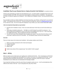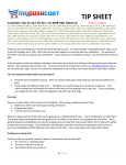
1
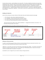
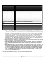
Installation Tips for your Remote Start/Keyless Entry (for Mazda Vehicles) v3.1 Updated 9/22/2012 Thank you for purchasing your remote start from MyPushcart.com - an industry leader in providing remote starts to doit-yourself installers since 1999. We’ve put this tip sheet together to help you with your installation. The purpose of this sheet is to help you organize your installation - not to replace your installation manual. You will still need to refer to that. If you provided us with your vehicle model/year at the time of purchase, you will have a wiring chart for your particular vehicle. We’re going to refer to that a lot. If you do not have the wiring chart, email us at [email protected] so we can send you a copy. Be sure to include the model/year of your vehicle, your name and your sales order number. Three very important things before you get started: Read the entire installation manual. There are several safety tips in there that you need to know before you start Avoid using a test light to probe wires. Test lights can set off air bags if you probe the wrong wire. Your vehicle wiring chart will identify the correct wires that you’ll be tapping on to in your car. If you must probe, use a digital multi-meter. They’re inexpensive and won’t set off air bags. You will need to have TWO valid ignition keys to program your bypass. If you do not have two keys, you will need to get a coded key from your Ford dealer. ALL Ford bypasses require two keys for programming. Overview There are 5 basic steps to this remote start installation. We’re going to address each of these: 1. 2. 3. 4. 5. Make your wiring connections for the remote start & bypass Program the bypass Test the system Connect the activation wire Button it up! Need to know where all the components go? See Installer’s Tip #1 on page 5 Step 1 – Wiring When you open up your remote start, you’re going to see a whole bunch of wires. You’re not going to use all of them. The remote starts are designed with wiring options for a variety of cars and no car is going to use all of them. We’re going to break the wiring down into three parts – your main power connections, what we’ll call your ‘secondary’ connections for your remote start, and connections for the bypass module. Your wiring chart will help you locate the wires that you’re going to need in your car. Don’t be intimidated by all the different wires listed on the chart – you’re only going to be using a few of them. 1|Page You also have an antenna, a small pushbutton and a status LED. The antenna should be mounted near the top of the windshield, at least 1” away from metal. Route the antenna cable underneath the headliner, down the windshield pillar and around the end of the dash. Carefully tuck the cable in behind the trim panels. The pushbutton is typically mounted in the driver’s kick panel (that’s the area forward of the door), the driver’s side of the center console, or the underside of the dash. Installation requires drilling a small hole in the plastic. The LED is not required for operation, but is helpful for programming or diagnostics. It also requires a hole and can be placed either near the pushbutton or on top of the dash. Reading your wiring chart Each line of the wiring chart contains 3 pieces of information that you will need (continued on next page): The “Function” column tells you what the wire function is The “Equipped” column tells you the color of the wire in the car The “Type” Column shows the location of the wire in the vehicle The “last column tells you the polarity of that wire, where applicable *Some wiring charts will include a column titled “Available Kits”. Disregard the information in this column. The information in this tip sheet is more concise. The sample below will show you where to find that information on your chart. Making your wiring connections The table on the following page will show you where to connect the wires from your remote start into the car. Any wires on your remote start that are NOT listed in the table are NOT USED. Helpful Hint: In most cases, the wires on the remote start are way longer than needed. Trim off excess wire when you make your connections, but leave some slack - this will allow you a little flexibility when it comes time to stow the remote start module after the installation is completed. See Installer’s Tip # 2 on Page 5 for tips on how to make your wiring connections 2|Page Remote Start Wire Red (6-pin harness, 2 wires) Pink (6-pin harness) Brown (6-pin harness) Grey (6-pin harness) Pink/White (6-pin harness) Connect to the wire for the circuit on the vehicle chart labeled: Constant 12 Volts Ignition 12-Volts Starter Accessory Ignition # 2 (not present on all vehicles) Black (12-pin harness) Yellow/Black (12-pin harness) System Ground – connect this to a solid metal ground in the car Connect to the brown wire on the IBF3 bypass – wait until you get to Step 2 before you do this! Connect to +12volts *or* Ground. See NOTE 1 Parking Lamp See NOTE 1 Brake Light (also called “Brake Switch”) Hood Input (See NOTE 2) Red/Black (12-pin harness) White (12-pin harness) Purple (12-pin harness) Grey (12-pin harness) Green (3-pin harness with WHITE plug) Blue (3-pin harness with WHITE plug) Orange/Black (12-pin harness) Red/White (12-pin harness) To Green Input wire on DLS Module (See NOTE 3) To Blue Input wire on DLS Module (See NOTE 3) The connections below MAY be needed OEM Alarm Disarm – use only if your car has a factory alarm system Tach Signal (See NOTE 4) NOTE 1 Some vehicles will call for a ‘+’ polarity connection to the parking light circuit and some will call for a ‘‘ connection. The red/black wire on the remote start is used to select the polarity of the remote start’s parking light output. If your vehicle’s parking light wire is shown with a ‘+’ on your wiring chart, connect the red/black wire to a constant +12v power source (you can tap it right on to one of the large red power input wires on the remote start’s 6-pin harness). If your vehicle’s parking light wire is shown with a ‘-’ on your wiring chart, connect the red/black wire to ground. The white wire in the remote start 12-pin harness is the actual parking light output wire. After you’ve properly selected it’s polarity using the red/black wire, connect the white wire to the parking light wire in your vehicle, as indicated on your wiring chart. NOTE 2 The grey wire is used with a pin switch (included in your kit) to prohibit the remote start from activating while the hood is open. This is an important safety feature! NOTE 3 Most Mazda vehicles will require the DLS door lock adapter module. The exceptions are the B-Series trucks, the 2007 CX9 and the 2009 MX-5 Miata. We’ll go in to detail in the “Wiring Your Door Locks” section below NOTE 4 Most vehicles will not require this connection. The remote start has a ‘tach sensing’ circuit built in. The purpose of that circuit (or the tach wire if you need it) is to enable the remote start to detect when the engine has started so it will stop cranking the starter. When you test your system, if the starter keeps cranking after the engine has started, you’ll need to connect the tach wire. Once the wire is connected, take two additional steps: 1) Change Programming Option #1 to the ‘tach’ setting (see installer’s manual). 2) Program the tach circuit as shown in the installation manual. Before proceeding to the bypass installation, plug in your antenna, pushbutton and LED. 3|Page Wiring Your Door Locks Most Mazda vehicles use a ‘single wire’ door lock system. Your wiring chart will tell you if your vehicle has the single wire system or a conventional 2-wire system. If you have a conventional 2-wire system (B-Series trucks, the 2007 CX9 and the 2009 MX-5 Miata), do not use the DLS module. Connect the blue and green ‘lock’ and ‘unlock’ wires from the remote start’s 3-pin white harness directly to the ‘lock’ and ‘unlock’ wires in the vehicle, as indicated on your wiring chart. If you have the single wire door lock system that is most common on Mazdas, locate the one door lock wire in the vehicle as indicated on your wiring chart. Then connect the DLS adapter as follows: Red – Constant +12v Black – Ground Green – to remote start green in 3-pin door lock harness Blue - to remote start blue in 3-pin door lock harness White – to the door lock wire in the vehicle. Once the wiring is completed, program the DLS according to the instructions on page 3 of the DLS manual Wiring your bypass The IBF3 comes with an installation guide. Only 5 connections are needed: Red – Constant +12v Black – Ground “TX” – to the PATS connector on your ignition switch assembly “RX” - to the PATS connector on your ignition switch assembly Ground When Running – to the yellow/black wire on the remote start’s 12-pin harness (remove the red plug from the brown wire if present) Identifying your RX and TX wires The IBF3 installation sheet has drawings of the various types of PATS connectors Ford/Mazda use. Find your PATS connector and identify which type it is as shown in the IBF3 manual. Use the pin-outs provided to determine which wires are RX and TX. Suggestion: Don’t use tap connectors on the RX and TX wires. The wires are small and sometimes a tap connector won’t make good contact. We suggest you either wrap and tape or solder and tape these connections. See Installer’s Tip #2 on page 5. Step 2 – Program the Bypass Instructions for programming your bypass are on the IBF3 sheet. Make sure you have both of your keys and your remote fob handy, as the programming actions MUST be done within only a few seconds - as detailed in the instructions. Read through the instructions first before actually doing the programming! It will help enable you to complete the steps within the specified time. 4|Page Step 3 –Test the System Make sure everything is working properly before you connect the activation wire and close up the installation. Once you’ve completed your wiring and have programmed the bypass, test the system by pressing the ‘start’ button on the remote fob. The ignition should turn on and shortly thereafter the car should start. Stop the engine by depressing the foot brake. Step 4 – Close it Up! Now gather up all your wiring and neatly bundle it together using zip ties or electrical tape. Find a secure place to put the remote start module and use zip ties to secure it. Make sure that the remote start wires are not near any moving parts on the steering wheel, pedals or emergency brake! Installer’s Tips Tip #1 – Where Everything Goes There are 4 parts to your system: 1. Remote start module – the wiring for the module is done under the dash on the driver’s side, so you’ll want to install the module in that general area. Before you start wiring, look for a location where there’s some open space that will fit the module. Pay attention to moving parts like the pedals, e-brake and steering column. Be sure to route your wiring away from those areas. 2. Bypass module – can be stowed along with the remote start. 3. Valet Switch – Requires a small screw hole. Usually put in the driver’s kick panel (that’s the area forward of the door), the driver’s side of the center console, or the underside of the dash. 4. Hood Pin Switch – An important safety component! Requires a 3/8” hole. Find a location in the engine compartment to mount the switch where the closed hood will keep the plunger in the switch depressed. This is what prevents the car from starting when the hood is open. Tip #2 – How to make your wiring connections It’s very important that all your wiring connections be solid and secure. All remote start connections are “tap on” connections. This means that you do not need to cut the wires in the car. You simply need to “tap on” to the wires in the car to make your connections. Here are three different ways to do this: Method 1 – Solder and tape This is the method preferred by the best professional installers. It makes for the most reliable connections, but it is also the most difficult to do. Sometimes there isn’t enough room in the wiring harness to safely solder a wire without damaging adjacent wires, but if you have the soldering skills, go for it. To make a connection, strip back a section of the insulation on the wire in the car. On heavy gauge wires, 1” is about the right amount. On lighter gauge wires, ½” is fine. Strip 1” of insulation off the end of the remote start wire. Tin the bare section of wire in the car. Wrap the remote start wire around the tinned section and then carefully solder it in place. Wrap the splice tightly with electrical tape. 5|Page Method 2 – Wrap and tape This is the most popular method and is also very reliable. Strip back a section of the insulation on the wire in the car. On heavy gauge wires, 1” is about the right amount. On lighter gauge wires, ½” is fine. Strip 1” of insulation off the end of the remote start wire. Separate the strands of the wire like this: Pass the wire from the remote through the opening as shown below Wrap the remote start wire around both sides of the car wire, then back around itself as shown below Use electrical tape to wrap the connection and secure the wires together. A wire tie will help prevent the tape from unraveling in the future. Method #3 – “T-Taps” T-taps are plastic clips that are squeezed onto the wires in the car. The wire from the remote start goes into the tap and the whole thing is crimped together. T-taps come in different sizes for different size wires. Use yellow t-taps for the larger wires in your main power harness. Red t-taps are good for the smaller wires. Tape and wire tie the connections as shown in the “wrap and tape” section above – that will prevent the t-taps from ever opening up. Using T-Taps Use a pair of pliers to attach the quick-connects to the wires in your car. Hold the quick connect as shown below in Figure 1, then clamp it on to the wire as shown in Figure 2. There is a locking tab at the front of the connector (Figure 3) – make sure it is secure and locked in place when you are done. Figure 1 Figure 2 6|Page Figure 3 Copyright 2012 Digitel LLC 7|Page