1
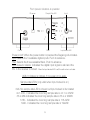
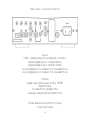
DAC-R
Digital to Analogue Converter
Contents
Introduction 1
Technology 2
Front panel indicators & operation
3
4
In use - Digital output & optical inputs
5
Back panel - inputs and outputs
Filter settings 6
Connectivity (examples)
USB set-up and connectivity
Remote control and notes on high resolution playback
7
8
9
Technical specifications 10
Glossary of terms
Owners log
11
12
Introduction
The Rega DAC-R is a 16/20/24-bit at 32kHz to 192kHz digital to analogue
converter. Incorporating an enhanced version of the Rega designed circuit,
the DAC-R offers the highest possible resolution over all inputs including
fully asynchronous USB with the addition of remote functionality.
Developed to be simple to set up and use, the Rega DAC-R is designed
to optimise performance from any two channel PCM digital audio source.
With the PC now widely accepted as a credible medium for storing and
streaming music,the use of high quality lossless files such as WAV, FLAC
and ALAC offer performance through the DAC-R equal to and in some
cases better than Red Book CD. Great care has been taken to remove
noise generated by the PC and other input sources. (During development
this was identified as a major drawback with many DAC’s on the market
today).
The DAC-R is housed in a custom aluminium and steel case and boasts
a pair of Wolfson DAC IC’s, three user selectable digital filters and one
isolated asynchronous USB, two isolated Co-axial inputs & two Toslink
SPDIF inputs.
The DAC-R has been designed and engineered to integrate perfectly into
any system and achieve the highest performance in its class. We hope
you enjoy this Rega product for many years to come.
1
Technology
The optical and coaxial input stage comprises a Wolfson digital receiver
with a high stability, low jitter clock driving the receiver PLL. The receiver and PLL have their own dedicated power supplies. The DAC stage
comprises a pair of parallel-connected Wolfson WM8742 DAC’s, that are
driven via a buffer stage, which ensures the integrity of the data being fed
to the DAC IC’s similar to the arrangement used in the Isis reference CDP.
The USB input stage is comprised of a bit perfect XMOS USB Audio 2.0
with asynchronous clocking. The USB input stage feeds the Optical and
Coaxial input stage via an isolating transformer giving total isolation from
the host computer.
The output amplifier employs a discrete differential, multiple feedback
filter and output amplifier, with a high cut-off frequency for use with higher
sample rates. We decided not to use a sample rate converter and process
the data at the incoming sample rate which keeps the signal processing to
a minimum. Jitter was minimised by synchronously clocking the digital data
with our receiver PLL (removing any jitter from the input signal).
All the capacitors associated with the analogue signal path are audio grade
bypassed with MMK polyester capacitors, and low impedance conductive polymer capacitors are used for DAC decoupling. The power supply
utilizes a toroidal transformer, fast rectifier diodes and again audio grade
capacitors. There is a power supply for the control micro controller, separate from the digital & analogue audio stages. Special attention being paid
to the inter IC control signals ensures the control data noise is kept to a
minimum.
2
Front panel indicators & operation
IR sensor
Sample Rate LED
On/Off
Filter
Input
Input locked LED
Power on/off When the power button is pressed the Rega logo illuminates.
Input Selects the 5 available digital inputs. Push to advance.
Filter Selects the three avaiaible filters. Push to advance
Input locked indicator Indicates the digital input signal is valid and the
PLL in the receiver is locked. When the Input locked LED is off, the soft mute is activated.
USB /1 Optical /2 Optical /3 Co-axial /4 Co-axial
Sample rate LED’s (only valid when Input locked is on).
32K- No sample rate LED is shown but Input locked is illuminated
44.1-48K - Indicates the incoming sample rate is 44.1 or 48kHz
88.2-96K-Indicates the incoming sample rate is 88.2 or 96kHz
176K - Indicates the incoming sample rate is 176.4kHz
192K - Indicates the incoming sample rate is 192kHz
3
Back panel - inputs and Outputs
Inputs
USB - Isolated Asyncronous/type B connector
Optical Digital Input 1- Optical/Toslink
Optical Digital Input 2- Optical /Toslink
Co-Ax Digital Input 3- Isolated 75Ω Co-axial Phono
Co-Ax Digital Input 4- Isolated 75Ω Co-axial Phono
Outputs
Digital output (via receiver & PLL) -SPDIF
Optical Toslink
Co-axial/Phono Isolated 75Ω
Analogue Output Left and Right Phono
Power Mains/line input IEC C13 type
Fuse Fuse holder
4
In use
Power-up the DAC-R using the power switch on the front panel. After a few
seconds you will hear an audible click from the output mute relay and the
analogue audio will be active. Please note: the front panel will display the
previously selected setting’s displayed before the unit was last powered
down. If the currently selected input has an active source connected, the
‘Input locked’ LED, along with the appropriate incoming sample rate LED,
will illuminate. Unless the Input locked LED is lit, the sample rate indication
is irrelevant. By pressing the input selection switch you can select any one
of the inputs. When the Input locked LED is off, or there is a transmission
error, the internal soft mute is activated automatically. By pressing the Filter
selection switch you can select any one of the 3 available digital filters.
(The exact properties of these filters are outlined on page 6). Notably, each
one has a different result at low and high sample rates. The differences,
although subtle, are more noticeable at higher samples rates.
Digital Output & Optical inputs
The digital output mirrors the selected input. For example, when input 2
has been selected, the digital output will be the signal present on input
2 but cleaned up and re-clocked. This can be used to drive an auxiliary
piece of equipment if so desired.
The optical system used for optical inputs 1&2 is nearing its maximum at
192K. If you experience difficulties try the following: Use a higher quality or shorter lead. When using 3.5mm jack outputs commonly found on
computers and sound cards etc. Try and use a mini Toslink optical 3.5mm
jack connector lead and avoid using a 3.5mm to full size adaptor with a
standard full size Toslink lead.
5
Filter settings
The cut-off points of the filters are in the upper end of the frequency range.
However, due to complex technical phenomena, this will have an effect
lower in the frequency band. For further description, see the glossary of
terms. These settings are a matter of personal taste and may only offer
subtle changes. We suggest using Filter setting 1 and trying different settings with various music and equipment.
Filter setting switch & LED’s - Push to advance to the next filter.
Filter settings 1–3
(low sample rates 32/44.1/48K)
1. Linear phase half-band filter
2. Minimum phase half-band filter
3. Minimum phase apodising filter
Filter settings 1–3
(medium & high sample rates 88.2/96 & 176.4/192K)
1. Linear phase soft-knee filter
2. Minimum phase brickwall filter
3. Linear phase apodising filter
The filters have a greater effect on higher sample rates because of the
higher Nyquist frequency which is ½ of the sample rate. This means the
filter has a wider frequency range in which to be active.
6
Connectivity (examples)
1 USB A-B/ 2 OPTICAL/3 CO-AXIAL
This page offers ‘suggested connectivity’. With so many products offering
a number of options, it is important to check the manual of the product
your are connecting for the appropriate or optimum output connection and
settings required to operate properly.
Please note : This unit only accepts two-channel PCM digital audio.You
cannot connect a Dolby Digital 5.1/7.1 or a DTS signal as they will not be
recognised. If you wish to connect a DVD or similar device, please ensure
that the sound output of your player is set to two-channel PCM.
7
USB Setup and connectivity
Connect a USB A-B type lead (as illustrated) from the DAC USB to a USB
output on your PC. IMPORTANT: Before you can use the USB function of
the DAC-R you must first download the Rega USB Windows driver and
install it on your PC. This driver is available for download from the Rega
website, www.rega.co.uk. Go to ‘product range’ and select CD players /
DAC’, then DAC-R. Under product downloads on the product page you
will see the USB driver. Follow the instruction for installation. Once installed,
USB will be ready to use. The driver is not required for MAC OS.
USB A-B Lead (not supplied)
It is recommended to switch off any other system sounds emitted by the
PC via the control panel. In some systems, the DAC-R will automatically
become the default for your PC whilst connected. Once disconnected,
the previous default should be restored. If this does not happen, you can
manually reset as follows:
Windows Vista - Control Panel / Hardware & Sound/Manage Audio
Devices/select ‘USB Audio’ from list.
Windows7 - Control Panel / Sound / Manage Audio Devices / select
USB Audio
Windows 8 - Control Panel / Hardware and Sound / Sound / Advanced /
select USB Audio
Mac OS - System Preferences / Sound Output / Select ‘USB DAC’.
8
Remote functionality
The DAC-R is supplied with a mini system remote
which gives the user the ability to switch inputs via
a single button marked ‘DAC Input’.
The Solaris system remote (sold separately) also
allows remote function of the three digital filters.
Notes on high resolution playback
The DAC-R can operate up to 192kHz when used with a capable
soundcard connected via the Co-axial, optical or USB input. Due to the
limitations of some operating systems and playback software, the exact
configuration and set-up can vary from one PC/laptop to another and may
not have a bit perfect high sample rate ‘signal’ path through the PC/laptop. It may be necssary to install further drivers in order to bypass the
Windows Audio drivers (for example ASIO4ALL). Select the new driver in
your chosen media player preferences. In some circumstances it is possible using the sound properties panel to make the DAC run at a higher
sample rate than that of the file being played, thus ‘up sampling’ the data
rate in the DAC. (sometimes called ‘bitty’ software sample rate conversion).
9
Technical Specifications
DAC 2x Wolfson WM8742
Frequency Response (100KΩ load) Filter 1 selected
Low data rate
44.1/48KHz = 10Hz -0.05dB to (44.1K) 20.02KHz (48K) 21.7KHz -0.03dB
Medium data rate
88.2/96KHz = 10Hz -0.05dB to (88.1K) 28.7KHz (96K) 31.2KHz -3dB
High data rate
176.4/192KHz = 10Hz -0.05dB to (176.4K) 44.1KHz (192K) 47.7KHz -3dB
Maximum output level = 2.175V into 100KΩ load
Bit resolution (all inputs) 16 to 24bit
Supported data rates = 32, 44.1, 48, 88.2, 96, 176.4, 192KHz
Total Harmonic Distortion all inputs (24bit 96KHz) = 0.006% @ 1KHz
Signal to Noise Ratio -105dB
(relative to maximum output level with a 100Hz to 22KHz bandwidth)
Digital inputs
USB Asynchronous Isolated (24bit 44.1/48/88.2/96/176.4/192KHz)
Input 1 Optical/Toslink (24bit 32/44.1/48/88.2/96/176.4/192KHz)
Input 2 Optical /Toslink (24bit 32/44.1/48/88.2/96/176.4/192KHz)
Input 3 Isolated 75Ω Co-axial (24bit 32/44.1/48/88.2/96/176.4/192KHz)
Input 4 Isolated 75Ω Co-axial (24bit32/44.1/48/88.2/96/176.4/192KHz)
Digital SPDIF outputs (via receiver & PLL)
Optical/Toslink
Isolated 75Ω Co-axial
Power 230v/115v/7.6W
Dimensions in cm W 21.5 x D 32 x H 8
Remote NEC system (6E91)
Weight 4.0 Kg
10
Glossary of terms
ASYNCHRONOUS
An asynchronous USB DAC uses its own clock to regulate the
data rate from the computer, which allows for jitter-free data transfer
PLL
Phase lock loop
PCM
Pulse code modulation
SPDIF
Sony Philips digital interface protocol
SOFT MUTE
Software mute (not output mute)
SOFT KNEE FILTER
Filter with a large transition band which reduces dispersion and delay
HALF BAND
Filter where the transition region is centred at one quarter of the
sampling rate
APODISING FILTER
Filter exhibiting a smooth roll off
BRICKWALL FILTER
Filter exhibiting a steep roll off
FLAC/ALAC
Examples of lossless audio formats
DIGITAL FILTER
Device or process that removes unwanted features from a signal.
11
Owners Log
(1)
Owner..................................................................................................
Date.....................................................................................................
Where purchased.................................................................................
(2)
Owner..................................................................................................
Date.....................................................................................................
Where purchased.................................................................................
(3)
Owner..................................................................................................
Date.....................................................................................................
Where purchased.................................................................................
(4)
Owner..................................................................................................
Date.....................................................................................................
Where purchased.................................................................................
(5)
Owner..................................................................................................
Date.....................................................................................................
Where purchased.................................................................................
12
Rega Research Ltd. exceptional hi-fi designed and made in England.