1
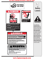
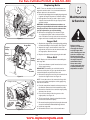
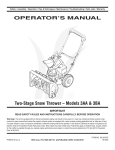
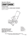
For Parts Call 606-678-9623 or 606-561-4983
Safety • Assembly • Operation • Tips & Techniques • Maintenance • Troubleshooting • Parts Lists • Warranty
OPERATOR’S MANUAL
Two-Stage Snow Thrower – Models 3AA & 3CA
IMPORTANT
READ SAFETY RULES AND INSTRUCTIONS CAREFULLY BEFORE OPERATION
Warning: This unit is equipped with an internal combustion engine and should not be used on or near any unimproved forest-covered, brushcovered or grass-covered land unless the engine’s exhaust system is equipped with a spark arrester meeting applicable local or state laws (if any).
If a spark arrester is used, it should be maintained in effective working order by the operator. In the State of California the above is required by law
(Section 4442 of the California Public Resources Code). Other states may have similar laws. Federal laws apply on federal lands. A spark arrester
for the muffler is available through your nearest engine authorized service dealer or contact the service department, P.O. Box 361131 Cleveland,
Ohio 44136-0019.
PRINTED IN U.S.A.
MTD LLC, P.O. BOX 361131 CLEVELAND, OHIO 44136-0019
www.mymowerparts.com
FORM NO. 769-00747E
5/31/2006
For Parts Call 606-678-9623 or 606-561-4983
This Operator’s Manual is an important part of your new snow thrower. It will help you assemble,
prepare, and maintain the unit for best performance. Please read and understand what it says.
Table of Contents
1.Safety Labels................................................ 3
2.Safe Operation Practices............................. 4
3.Setup and Adjustment................................. 6
4.Know Your Snow Thrower............................ 8
5.Operating Your Snow Thrower..................... 9
6.Maintenance & Service.............................. 12
7.Off-Season Storage.................................... 14
8.Troubleshooting.......................................... 15
9.Parts List..................................................... 16
Warranty.......................................Back Cover
This Operators Manual covers a range of product specifications for various models. Characteristics and features discussed and/or illustrated in this manual may not be applicable to all models. MTD LLC reserves the right to change product specifications, designs and equipment without notice and without incurring obligation.
Finding and Recording Model Number
BEFORE ASSEMBLING YOUR NEW EQUIPMENT,
please locate the model plate on the equipment
and copy the information to the sample model plate
provided to the right. You can locate the model plate
by standing at the operating position and looking
down at the rear of the snow thrower. This information will be necessary to use the manufacturer’s web
site, to obtain assistance from the Customer Support
Department, or when contacting an authorized service
dealer.
Model Number
Serial Number
Customer Support
Please do NOT return the unit to the retailer from which it was purchased, without first
contacting Customer Support.
If you have difficulty assembling this product or have any questions regarding the controls, operation, or maintenance of this unit,
you can seek help from the experts. Choose from the options below:
• Visit www.mtdproducts.com
• Call a Customer Support Representative at 1-800-800-7310.
• The engine manufacturer is responsible for all engine-related issues with regards to performance, power-rating, specifications, warranty and service. Please refer to the engine manufacturer’s Owner’s/Operator’s Manual, packed separately with
your unit, for more information.
www.mymowerparts.com
For Parts Call 606-678-9623 or 606-561-4983
FOR TURNING,
NOT LIFTING
DANGER
$!.'%2
!6/)$).*529&2/-2/4!4).'
!5'%2+%%0(!.$3&%%4
!.$#,/4().'!7!9
NEVER PUT HAND IN CHUTE. CONTACT WITH
ROTATING PARTS CAN AMPUTATE FINGERS
AND HANDS.
SHUT OFF ENGINE AND WAIT UNTIL ALL
MOVING PARTS HAVE STOPPED BEFORE
UNCLOGGING.
USE CLEAN-OUT TOOL OR WOODEN STICK TO
UNCLOG DISCHARGE CHUTE.
$!.'%2
+%%0!7!9&2/-2/4!4).')-0%,,%2!.$!5'%2#/.4!#4
7)4()-0%,,%2/2!5'%2#!.!-054!4%(!.$3!.$&%%4
53%#,%!./544//,
4/5.#,/'$)3#(!2'%#(54%
$)3%.'!'%#,54#(,%6%2334/0%.').%!.$2%-!).
"%().$(!.$,%35.4),!,,-/6).'0!243(!6%34/00%$
"%&/2%5.#,/'').'/23%26)#).'-!#().%
4/!6/)$4(2/7./"*%#43).*52)%3.%6%2$)2%#4 $)3#(!2'%!4"934!.$%2353%%842!#!54)/.7(%.
/0%2!4).'/.'2!6%,352&!#%3
2%!$/0%2!4/2g3-!.5!,
AVOID SERIOUS INJURY FROM TIRE / RIM EXPLOSION.
TO PREVENT OVER-INFLATION:
• USE A MANUAL PUMP OR PORTABLE ELECTRIC
TIRE INFLATOR.
• NEVER USE AN AIR COMPRESSOR.
• INFLATE TIRE TO 20 PSI.
www.mymowerparts.com
1
Safety
Labels
WARNING
This symbol points
out important safety
instructions which, if not
followed, could endanger
the personal safety and/or
property of yourself and
others. Read and follow
all instructions in this
manual before attempting
to operate this machine.
Failure to comply with
these instructions may
result in personal injury.
When you see this symbol
HEED ITS WARNING!
Restrict the use of this
power machine to persons
who read, understand and
follow the warnings and
instructions in this manual
and on the machine.
For Parts Call 606-678-9623 or 606-561-4983
2
Safe
Operation
Practices
WARNING
This symbol points
out important safety
instructions which, if
not followed, could
endanger the personal
safety and/or property
of yourself and others.
Read and follow all
instructions in this
manual before attempting to operate
this machine. Failure
to comply with these
instructions may result
in personal injury. When
you see this symbol.
WARNING: Engine Exhaust, some of its constituents, and certain vehicle components contain or emit chemicals known to State of California to cause cancer and
birth defects or other reproductive harm.
DANGER: This machine was built to be operated according to the rules for safe operation in this
manual. As with any type of power equipment, carelessness or error on the part of the operator can
result in serious injury. This machine is capable of amputating hands and feet and throwing objects.
Failure to observe the following safety instructions could result in serious injury or death.
Training
Preparation
1. Read, understand, and follow all instructions on the
machine and in the manual(s) before attempting to
assemble and operate. Keep this manual in a safe place for
future and regular reference and for ordering replacement
parts.
2. Be familiar with all controls and their proper operation.
Know how to stop the machine and disengage them quickly.
3. Never allow children under 14 years old to operate this
machine. Children 14 years old and over should read and
understand the operation instructions and safety rules in
this manual and should be trained and supervised by a
parent.
4. Never allow adults to operate this machine without proper
instruction.
5. Thrown objects can cause serious personal injury. Plan
your snow-throwing pattern to avoid discharge of material
toward roads, bystanders, and the like.
6. Keep bystanders, helpers, pets, and children at least 75
feet from the machine while it is in operation. Stop machine
if anyone enters the area.
7. Exercise caution to avoid slipping or falling, especially
when operating in reverse.
1. Thoroughly inspect the area where the equipment is to be
used. Remove all doormats, newspapers, sleds, boards,
wires, and other foreign objects, which could be tripped over
or thrown by the auger/impeller.
2. Always wear safety glasses or eye shields during operation
and while performing an adjustment or repair to protect your
eyes. Thrown objects which ricochet can cause serious
injury to the eyes.
3. Do not operate without wearing adequate winter outer
garments. Do not wear jewelry, long scarves, or other
loose clothing which could become entangled in moving
parts. Wear footwear which will improve footing on slippery
surfaces.
4. Use a grounded three-wire extension cord and receptacle
for all units with electric start engines.
5. Adjust collector housing height to clear gravel or crushed
rock surfaces.
6. Disengage all control levers before starting the engine.
7. Never attempt to make any adjustments while engine is
running, except where specifically recommended in the
operator’s manual.
8. Let engine and machine adjust to outdoor temperature
before starting to clear snow.
9. To avoid personal injury or property damage use extreme
care in handling gasoline. Gasoline is extremely flammable
and the vapors are explosive. Serious personal injury can
occur when gasoline is spilled on yourself or your clothes,
which can ignite. Wash your skin and change clothes
immediately.
a. Use only an approved gasoline container.
b. Extinguish all cigarettes, cigars, pipes and other sources
of ignition.
c. Never fuel machine indoors.
d. Never remove gas cap or add fuel while the engine is hot
or running.
e. Allow engine to cool at least two minutes before refueling.
f. Never over fill fuel tank. Fill tank to no more than ½-inch
below bottom of filler neck to provide space for fuel
expansion.
g. Replace gasoline cap and tighten securely.
h. If gasoline is spilled, wipe it off the engine and equipment. Move machine to another area. Wait five minutes
before starting the engine.
i. Never store the machine or fuel container inside where
there is an open flame, spark or pilot light (e.g. furnace,
water heater, space heater, clothes dryer etc.).
j. Allow machine to cool at least five minutes before
storing.
HEED ITS WARNING!
Your Responsibility
Restrict the use
of this power machine
to persons who read,
understand
and follow the warnings
and instructions
in this manual
and on the machine.
www.mymowerparts.com
For Parts Call 606-678-9623 or 606-561-4983
Operation
Maintenance & Storage
1. Do not put hands or feet near rotating parts, in the
auger/impeller housing or chute assembly. Contact with the
rotating parts can amputate hands and feet.
2. The auger/impeller control lever is a safety device. Never
bypass its operation. Doing so makes the machine unsafe
and may cause personal injury.
3. The control levers must operate easily in both directions
and automatically return to the disengaged position when
released.
4. Never operate with a missing or damaged chute assembly.
Keep all safety devices in place and working.
5. Never run an engine indoors or in a poorly ventilated area.
Engine exhaust contains carbon monoxide, an odorless and
deadly gas.
6. Do not operate machine while under the influence of alcohol
or drugs.
7. Muffler and engine become hot and can cause a burn. Do
not touch.
8. Exercise extreme caution when operating on or crossing
gravel surfaces. Stay alert for hidden hazards or traffic.
9. Exercise caution when changing direction and while operating on slopes.
10.Plan your snow-throwing pattern to avoid discharge towards
windows, walls, cars etc. Thus, avoiding possible property
damage or personal injury caused by a ricochet.
11.Never direct discharge at children, bystanders, and pets or
allow anyone in front of the machine.
12.Do not overload machine capacity by attempting to clear
snow at too fast of a rate.
13.Never operate this machine without good visibility or light.
Always be sure of your footing and keep a firm hold on the
handles. Walk, never run.
14.Disengage power to the auger/impeller when transporting or
not in use.
15.Never operate machine at high transport speeds on slippery
surfaces. Look down and behind and use care when
backing up.
16.If the machine should start to vibrate abnormally, stop the
engine, disconnect the spark plug wire and ground it against
the engine. Inspect thoroughly for damage. Repair any
damage before starting and operating.
17.Disengage all control levers and stop engine before you
leave the operating position (behind the handles). Wait
until the auger/impeller comes to a complete stop before
unclogging the chute assembly, making any adjustments, or
inspections.
18.Never put your hand in the discharge or collector openings.
Always use the clean-out tool provided to unclog the discharge opening. Do not unclog chute assembly while engine
is running. Shut off engine and remain behind handles until
all moving parts have stopped before unclogging.
19.Use only attachments and accessories approved by the
manufacturer (e.g. wheel weights, tire chains, cabs etc.).
20.If situations occur which are not covered in this manual, use
care and good judgment. Contact your dealer or call the
customer service number found on page two.
1. Never tamper with safety devices. Check their proper
operation regularly. Refer to the maintenance and adjustment sections of this manual.
2. Before cleaning, repairing, or inspecting machine disengage all control levers and stop the engine. Wait until the
auger/impeller come to a complete stop. Disconnect the
spark plug wire and ground against the engine to prevent
unintended starting.
3. Check bolts and screws for proper tightness at frequent
intervals to keep the machine in safe working condition.
Also, visually inspect machine for any damage.
4. Do not change the engine governor setting or over-speed
the engine. The governor controls the maximum safe
operating speed of the engine.
5. Snow thrower shave plates and skid shoes are subject to
wear and damage. For your safety protection, frequently
check all components and replace with original equipment
manufacturer’s (OEM) parts only. “Use of parts which do
not meet the original equipment specifications may lead to
improper performance and compromise safety!”
6. Check controls periodically to verify they engage and
disengage properly and adjust, if necessary. Refer to the
adjustment section in this operator’s manual for instructions.
7. Maintain or replace safety and instruction labels, as necessary.
8. Observe proper disposal laws and regulations for gas, oil,
etc. to protect the environment.
9. Prior to storing, run machine a few minutes to clear snow
from machine and prevent freeze up of auger/impeller.
10.Never store the machine or fuel container inside where
there is an open flame, spark or pilot light such as a water
heater, furnace, clothes dryer etc.
11.Always refer to the operator’s manual for proper instructions
on off-season storage.
Do not modify engine
To avoid serious injury or death, do not modify engine in any
way. Tampering with the governor setting can lead to a runaway
engine and cause it to operate at unsafe speeds. Never tamper
with factory setting of engine governor.
Notice regarding Emissions
Engines which are certified to comply with California and federal
EPA emission regulations for SORE (Small Off Road Equipment)
are certified to operate on regular unleaded gasoline, and may
include the following emission control systems: Engine Modification (EM) and Three Way Catalyst (TWC) if so equipped.
Your Responsibility
Restrict the use of this power machine to persons who read, understand and follow the warnings and instructions in this manual
and on the machine.
www.mymowerparts.com
2
Safe
Operation
Practices
WARNING
This symbol points
out important safety
instructions, which if
not followed, could
endanger the personal
safety and/or property
of yourself and others.
Read and follow all
instructions in this manual before attempting to
operate this machine.
Failure to comply with
these instructions may
result in personal injury.
When you see this
symbol.
HEED IT’S WARNING!
Your Responsibility
Restrict the use
of this power machine
to persons who read,
understand
and follow the warnings
and instructions
in this manual
and on the machine.
3
For Parts Call 606-678-9623 or 606-561-4983
Setup and
Adjustment
IMPORTANT: This unit is shipped with the engine full of
oil. After assembly, see Operation section for fuel and
oil details.
Chute Handle
Before Assembly
WARNING: Disconnect the spark plug
wire and Ground it against the engine to
prevent unintended starting.
2
NOTE: Reference to right, left, front, or rear of the unit is
from the operating position unless otherwise stated.
Upper
Chute
1
1. Cut the cable tie that secures the upper handle to
the chute assembly for shipping purposes.
Setting Up The Handle
WARNING
Disconnect the spark
plug wire and ground it
against the engine to
prevent unintended
starting.
Do not use the chute
handle to lift the snow
thrower.
Over-inflating the tire with
excessive pressure (well
above 20 psi) may cause
the tire/rim to burst with
sufficient force to cause
serious pressure.
1. Loosen the chute knob on the upper chute(1) and
pivot the upper chute upwards(2) as far as it will go.
See Figure 1.
Figure 1
WARNING: Do not lift the snow thrower by
the chute handle.
2. Loosen the handle knob and handle tab on each
side of the handle. See Figure 2.
1
3. Hold both controls against upper handle and pull up
as shown in Step 1 of Figure 3. Make sure that the
upper handle locks over the lower handle and handle
tabs align with the handle. You may have to carefully
maneuver the upper handle to clear chute assembly.
CAUTION: Be careful not to bend or kink the cable.
4. Tighten the handle knobs on each side of the
handle. Refer to Step 2 in Figure 3.
5. Adjust upper chute and rotate chute handle to
desired operating position.
6. Tighten the chute knob on the upper chute making
sure the carriage bolt is correctly positioned. Refer to
Figure 1.
Clean-Out Tool
Figure 2
This tool and the electric extension cord, if so equipped,
may be fastened with a cable tie to the rear of the auger
housing for shipping purposes. In that case, cut the
cable tie and remove the extension cord now.
1
Final Adjustments
IMPORTANT: Check the adjustments as instructed and
make any final adjustments necessary before operating
the unit. Check all nuts and bolts for tightness. Failure to
follow these instructions may cause damage to unit.
Tire Pressure
All references to left
or right side of the snow
thrower is from the
operating position only.
The proper inflation pressure is 20 psi. Check the tire
pressure periodically and maintain equal pressure in both
tires at all times. Excessive pressure (well above 20 psi)
may cause the wheel (tire/rim) assembly to burst with
sufficient force to cause serious injury. Do not over-inflate
the tire. Use a manual pump or portable electric tire
inflator to prevent over-inflation. NEVER USE AN AIR
COMPRESSOR.
2
Figure 3
www.mymowerparts.com
For Parts Call 606-678-9623 or 606-561-4983
Skid Shoe
The space between the shave plate and the ground can
be adjusted. Refer to Figure 7 for location of shave plate
and skid shoes.
For close snow removal, place skid shoes in the low
position. When the area to be cleared is uneven, place
skid shoes in the middle or high position. See Figure 4.
NOTE: It is not recommended that you operate this
snow thrower on gravel as loose gravel can be easily
picked up and thrown by the auger causing personal
injury or damage to the snow thrower. However, if you
have to operate it on gravel, keep the skid shoe in the
highest position for maximum clearance.
High Position
Middle Position
Low Position
1. Adjust skid shoes by loosening two hex nuts and
carriage bolts on each skid shoe, and move the skid
shoe to the desired position. See Figure 4.
Figure 4
2. Make certain the entire bottom surface of skid shoe
is against the ground to avoid uneven wear on the
skid shoes.
3. Tighten nuts and bolts securely.
Routing The Drive Cable
1. Make sure that the drive cable is routed parallel to
the left upper handle, then across the top of the
lower handle and finally parallel to the right lower
handle. See Figure 5.
Drive Cable
Cable Ties
Auger Cable
2. Three cable ties have been used to loosely tie the
two control cables to the lower handle. Two of these
cable ties are on each arm, and the third on the top
cross bar of the lower handle. Tighten these cable
ties to secure the cable to the lower handle. See
Figure 5.
Adjusting Auger Cable
Figure 5
Periodic adjustment to the auger control cable may be
required due to normal stretch and wear on the belt.
Adjustment is needed if the augers seem to hesitate
while turning, but the engine maintains speed, or
continue turning with the auger control disengaged.
1. Loosen the rear hex bolt on the cable adjustment
bracket. See Figure 6.
2. Slide the cable adjustment bracket backwards
taking out the slack in the auger cable.
3. Retighten the rear hex bolt.
4. Start engine and verify auger control engages and
disengages properly.
NOTE: If auger continues to rotate with the control
disengaged, shut off engine and readjust.
WARNING: Do not over-tighten the
cable. Over-tightening may prevent the
auger from disengaging and compromise the safety of the snow thrower.
Figure 6
www.mymowerparts.com
3
Setup and
Adjustment
WARNING
Do not over-tighten the
cable. Over-tightening
may prevent the auger
from disengaging and
compromise the safety of
the snow thrower.
IMPORTANT: Check
the adjustments as
instructed and make any
final adjustments necessary before operating
the unit. Check all nuts
and bolts for tightness.
Failure to follow these
instructions may cause
damage to unit.
NOTE: It is not recommended that you operate
this snow thrower on
gravel as loose gravel
can be easily picked
up and thrown by the
auger causing personal
injury or damage to the
snow thrower. However,
if you have to operate
it on gravel, keep the
skid shoe in the highest
position for maximum
clearance.
For Parts Call 606-678-9623 or 606-561-4983
4
WARNING: Be familiar with all the controls on the snow thrower and their proper operation. Know
how to stop the machine and disengage them quickly.
Compare Figure 7 with your equipment and follow description of controls, given below, to become familiar with their
operation.
Auger Control
Know
Your Snow
Thrower
Upper Handle
Drive Control
Starter Rope
Gasoline Cap
Upper Chute
Chute Handle
Muffler
Chute Assembly
Clean-Out Tool
WARNING
Become familiar with all
the controls on the snow
thrower and their proper
operation. Know how to
stop the machine and
disengage them quickly.
Never make adjustments to
the chute assembly unless
both auger and drive
controls are disengaged
and the operator is standing beside the unit.
Chute Knob
Auger
Shave Plate
Oil Fill
Spark
Plug
Fuel Cap
Carburetor
Cover
Starter
Handle
Choke
Skid Shoe
Throttle
Control
Oil Drain
Primer
Figure 7
Throttle Control
Chute Handle
The throttle control is located on the engine. It regulates
the speed of the engine and also stops the engine.
The direction of snow throwing corresponds to the
direction of the chute opening. Use the chute handle to
turn the chute assembly in the direction you wish to throw
the snow.
Drive Control
Located on the underside of the upper handle, the drive
control is used to engage/disengage wheels. Squeeze
the drive control against the upper handle to engage the
wheels; release to disengage.
Chute Knob
The distance snow is thrown can be adjusted by either
raising or lowering the upper chute. Loosen the chute
knob on the side of the upper chute to adjust. Pivot the
upper chute to desired position, and retighten the chute
knob.
Auger Control
The auger control is adjacent to the upper handle.
Squeeze the auger control against the upper handle to
engage the augers; release to disengage the augers.
Ignition Key
WARNING: Never make adjustments to
the chute assembly unless both auger
and drive controls are disengaged and
the operator is standing beside the unit.
The ignition key is necessary for the engine to start.
Insert key and snap in place; Do not turn it to start/stop
the unit. Remove key when the unit is not in use.
IMPORTANT: Refer to the Auger Control Test in the
Operation section prior to operating your snow thrower.
Read and follow all instructions carefully and perform
all adjustments to verify your snow thrower is operating
safely and properly.
The shave plate maintains contact with pavement as
the snow thrower is propelled, allowing snow close to
pavement’s surface to be discharged.
Shave Plate
Skid Shoe
The space between the shave plate and the ground can
be adjusted. For close snow removal, place skid shoes in
the low position. Use middle or high position when area to
be cleared is uneven or on gravel surfaces.
Gasoline Cap
Remove gas cap to add fuel. Unit runs on regular gas.
www.mymowerparts.com
For Parts Call 606-678-9623 or 606-561-4983
Before Starting Engine
and free from rust or other foreign particles. Make
sure to wipe off any spilled fuel before starting the
engine.
Engine Oil
The engine is shipped with oil in it. Check the oil level
before first use.
5. At the end of the job, empty the fuel tank if the snow
thrower is not going to be used for 30 days or longer.
Store gasoline in a clean container and keep the cap
in place on the container.
1. Stop engine and wait several minutes before checking
oil level. Remove oil fill cap and dipstick.
2. Wipe dipstick clean, insert it into oil fill hole, and
tighten securely.
5
Operation
CAUTION: Never use engine or carburetor cleaner
products in the fuel tank.
3. With engine on level ground, oil must be to FULL mark
on dipstick. See Figure 8. If oil level is low, add oil.
To Start Engine
WARNING: Be sure no one other than
the operator is standing near the snow
thrower while starting or operating. Do
not operate this snow thrower unless
the chute assembly has been properly installed and
is secured.
FULL
For location of all the engine controls referred to in this
section, see the engine owner’s manual.
Maintain Oil Level
Between FULL and ADD
Recoil Starter–Cold Start
ADD
1. Make sure that auger and drive controls are
released. Attach spark plug wire to spark plug.
2. Turn fuel valve on, if so equipped.
3. Move throttle control to FAST position.
Figure 8
Adding Engine Oil
4. Push key into the ignition slot so that it snaps into
place. Do not turn key.
Be sure to use the grade of engine oil specified in engine
manual. To add oil:
5. Rotate choke control to FULL choke position.
6. Push primer button while covering the vent hole.
Remove your finger from the primer between primes.
Do not prime if temperature is above 50º F; prime
two times between 50º F and 15º F; and prime four
times below 15º F.
1. Remove the dipstick from the oil fill. Pour fresh oil
slowly through the plug. Replace dipstick.
2. Check and make sure that the level of oil is up to the
FULL mark on the dipstick.
IMPORTANT: For detailed engine information, see the
separate engine owner’s manual included with this unit.
7. Grasp starter handle and pull rope out slowly until engine
reaches start of compression cycle (rope will pull
slightly harder at this point). Let the rope rewind slowly.
Gasoline
WARNING: Gasoline is flammable and
caution must be used when handling or
storing it. Do not fill fuel tank while the
snow thrower is running, when it is hot
or when it is in an enclosed area.
8. Pull rope with a rapid, continuous, full arm stroke.
Keeping a firm grip on the starter handle, let the rope
return to the starter slowly. Repeat until engine starts.
9. As the engine warms up, rotate the choke knob slowly
to OFF position. If the engine falters, return to FULL
choke, then slowly move to OFF choke position.
WARNING: Keep your snow thrower away
from any open flame or an electrical spark
and do not smoke during fueling.
10.Allow the engine to warm up for a few minutes
because the engine will not develop full power until it
reaches operating temperature.
3. Never fill the fuel tank completely. Fill the tank to
no more than 1/2-inch below bottom of filler neck to
provide space for expansion of fuel.
11.Operate the engine at full throttle (FAST) when
throwing snow.
NOTE: This unit may include a fuel plug, which is only
used during assembly to keep dirt and debris out of fuel
tank. Discard the fuel plug before filling the fuel tank.
Warm Start:
1. If restarting an engine after a temporary shut-down,
rotate choke to OFF instead of FULL and do not
prime. Pull starter handle as instructed before.
4. Always use clean, fresh, unleaded grade automotive
gasoline. Fill the fuel tank outdoors and use a funnel
or spout to prevent spilling. Make sure that the
container from which you pour the gasoline is clean
www.mymowerparts.com
WARNING
Gasoline is flammable
and caution must be used
when handling or storing
it. Do not fill fuel tank
while the snow thrower is
running, when it is hot or
when it is in an enclosed
area.
Keep your snow thrower
away from any open flame
or an electrical spark
and do not smoke during
fueling.
Be sure no one other than
the operator is standing
near the snow thrower
while starting or operating. Do not operate this
snow thrower unless the
chute assembly has been
properly installed and is
secured.
The electric starter must
be properly grounded at
all times to avoid the possibility of electric shock
to the operator. If your
house wiring system is
not a three-wire grounded
system, do not use this
electric starter under any
conditions.
For Parts Call 606-678-9623 or 606-561-4983
5
Operation
Electric Starter(if equipped)
Some models of the snow thrower may be equipped with
an optional 120 volt A.C. electric starter. This electric
starter, with a three-wire power cord and plug, is designed
to operate on a 120 volt AC household current. Follow the
steps below to use the electric starter.
Cold Start:
1. Determine whether your house wiring is a three-wire
grounded system. Ask a licensed electrician if you are
not certain.
WARNING
Severe damage to electric
starter (if equipped) is
possible if you continue
to crank for more than
five seconds without a
cool-down.
The temperature of muffler
and the surrounding areas
may exceed 150˚F. Avoid
these areas.
WARNING: The electric starter must be
properly grounded at all times to avoid
the possibility of electric shock to the
operator. If your house wiring system
is not a three-wire grounded system, do not use this
electric starter under any conditions.
2. If your house wiring system is grounded and a threehole receptacle is not available at the point the snow
thrower starter will normally be used, one should be
installed by a licensed electrician.
NOTE: When connecting the power cord, always connect
cord to starter on engine first, then plug the other end into
a three-hole grounded 120 Volt receptacle. When disconnecting the power cord, always unplug the end from the
three-hole, grounded receptacle first.
3. Attach spark plug wire to spark plug.
4. Make sure that the auger control and the drive control
are disengaged.
5. Remove the keys from the plastic bag. Push key into
the ignition slot. Do not turn the key. Keep second key
in a safe place.
6. Move the choke knob to FULL choke position.
7. Move throttle control to the FAST position.
8. Turn fuel valve on, if so equipped.
9. Connect power cord to the switch box on engine.
10.Plug the other end of the power cord into a three-hole,
grounded 120 volt AC receptacle.
11.Push primer button three times.
12.Push down on the starter button until the engine starts.
Do not crank for more than five seconds at a time.
WARNING: Severe damage to electric
starter is possible if you continue
to crank for more than five seconds
without a cool-down.
13.When the engine starts, release the starter button and
slowly rotate the choke to OFF position. If the engine
falters, rotate the choke to FULL and then gradually to
OFF.
NOTE: When engaging the electric starter, a slight hesitation of a few seconds may occur before the engine starts
to turn. This is normal and is not harmful to the engine.
14.Disconnect the power cord from the receptacle first
and then from the switch box on the engine.
15.Allow the engine to warm up for a few minutes
because the engine will not develop full power until it
reaches operating temperature.
NOTE: If the starter motor runs but the engine does not
turn over, the starter gear may have frozen. Place the
snow thrower in a warmer part of the garage or storage
shed till the gear is free of the accumulated ice.
Warm Start:
1. If restarting a warm engine, rotate choke to OFF
instead of FULL and press the starter button. Do not
push the primer button.
Before Stopping
1. Run engine for a few minutes to help dry off any
moisture on engine.
2. To avoid possible freeze-up of the starter, follow these
steps:
Recoil Starter
a. With the engine running, pull the starter rope with a rapid, continuous full arm stroke three or four times.
Electric Starter (if equipped)
a. Connect power cord to switch box, then to 120 Volt AC receptacle.
b. While the engine is running, push the starter button and spin the starter for several seconds.
c. Disconnect power cord from the receptacle first, then from the snow thrower.
NOTE: The unusual sound from pulling the starter rope or
from spinning the starter will not harm the engine.
3. While standing in the operator’s position (behind the snow
thrower), engage the auger control for a few seconds to
clear any remaining snow and ice from the chute assembly.
To Stop The Snow Thrower
1. To stop the wheels, release the drive control.
2. To stop throwing snow, release the auger control.
3. To stop engine, push throttle control lever to OFF or
pull out the key(either method works). Do not turn key.
WARNING: The temperature of muffler and
the surrounding areas may exceed 150º F.
Avoid these areas
Auger Control Test
IMPORTANT: Perform the following test before operating
the snow thrower for the first time and at the start of each
winter season.
Check the adjustment of the auger control as follows:
1. When the auger control is released and in the
disengaged “up” position, the cable should have very
little slack, but should NOT be tight.
10
www.mymowerparts.com
For Parts Call 606-678-9623 or 606-561-4983
Operating Tips
WARNING: Do not over-tighten the
cable. Over-tightening may prevent the
auger from disengaging and compromise the safety of the snow thrower.
• For most efficient snow removal, remove snow
immediately after it falls.
• Discharge snow downwind whenever possible. Slightly
overlap each previous path.
2. In a well-ventilated area, start the snow thrower
engine as instructed earlier in this section under the
heading Starting Engine. Make sure the throttle is set
in the FAST position.
• Set the skid shoes 1/4-inch below the shave plate
for normal usage. The skid shoes may be adjusted
upward for hard-packed snow.
3. While standing in the operator’s position (behind the
snow thrower) engage the auger.
4. Allow the auger to remain engaged for approximately
10 seconds before releasing the auger control. Repeat
this several times.
5. With the engine running in the FAST position and the
auger control in the disengaged “up” position, walk to
the front of the machine.
• If for some reason, you have to operate the snow
thrower on gravel, keep the skid shoe in the highest
position for maximum clearance between the ground
and the shave plate.
• Clean the snow thrower thoroughly after each use.
IMPORTANT: If the auger shows ANY signs of rotating,
immediately return to the operator’s position and shut
off the engine. Wait for all moving parts to stop before
readjusting the auger control cable as shown in the
“Setup and Adjustment” section.
The clean-out tool is conveniently fastened to the rear of
the auger housing with a mounting clip. When snow and
ice collect in the chute assembly during operation, use
this tool to safely clean the chute and chute opening.
Cleaning The Chute Assembly
WARNING: Stop engine by moving
throttle lever to stop position and wait
for all moving parts to stop before using
the clean-out tool.
CAUTION: Check the area to be cleared for foreign
objects. Remove, if any.
1. Start the engine following starting instructions.
1. Release both auger and drive controls.
2. Allow the engine to warm up for a few minutes as
the engine will not develop full power until it reaches
operating temperature.
2. Stop the engine by moving throttle lever to stop
position.
3. Rotate the chute assembly to the desired direction,
away from bystanders and/or buildings.
3. Remove the clean-out tool from the clip which secures
it to the rear of the auger housing.
4. Making certain no bystanders or obstacles are in
front of the unit, squeeze the auger control completely
against the upper handle to fully engage the augers.
4. Use the shovel-shaped end of the clean-out tool to
dislodge and scoop any snow and ice which has
formed in and near the chute assembly.
5. While the auger control is engaged, squeeze the drive
control completely against the upper handle to engage
the wheels. Do not “feather” the drive control.
WARNING: Never use your hands to
clean snow and ice from the chute
assembly or auger housing.
5. Refasten the clean-out tool to the mounting clip on the
rear of the auger housing.
6. As the snow thrower begins to move, maintain a firm
hold on the handle, and guide the snow thrower along
the path to be cleared.
7. Release the auger and drive controls to stop the snow
throwing action and forward motion.
NOTE: Your unit is equipped with a clutch in the transmission. If the wheels stop turning while trying to discharge
large volumes of snow, immediately disengage the drive
control and allow the rotating augers to discharge snow
from the housing. Reduce the clearing width and continue
operation.
8. On each succeeding pass, readjust the chute
assembly to the desired position and slightly overlap
the previously cleared path.
11
Operation
NOTE: It is not recommended that you operate this snow
thrower on gravel as loose gravel can be easily picked up
and thrown by the auger causing personal injury and/or
damage to the snow thrower.
6. Confirm that the auger has completely stopped
rotating and shows NO signs of motion.
Clearing The Snow
5
www.mymowerparts.com
WARNING
Do not over-tighten the
cable. This may prevent the
auger from disengaging
and compromise
the safety of the snow
thrower.
Stop engine by moving
throttle lever to stop position and wait for all moving
parts to stop before using
the clean-out tool.
Never use your hands to
clean snow and ice from
the chute assembly or
auger housing.
When preparing to clear
snow, be sure to check
the area to be cleared for
foreign objects. Remove
objects, if any.
6
For Parts Call 606-678-9623 or 606-561-4983
Maintenance
& Service
General Recommendations
Shear Pin
• Always observe safety rules when performing any
type of maintenance.
• The warranty on this snow thrower does not cover
items that have been subjected to operator abuse or
negligence. To receive full value from the warranty, operator must maintain the snow thrower as
instructed in this manual.
• Periodically check all fasteners and hardware to
make sure these are tight.
Cotter Pin
Skid Shoe
Carriage
Shave Plate
Bolt
WARNING: Before servicing, repairing,
lubricating, or inspecting, disengage all
controls and stop engine. Wait until all
moving parts have come to a complete
stop. Disconnect spark plug wire and ground it against
the engine to prevent unintended starting. Always wear
safety glasses during operation or while performing
any adjustments or repairs.
WARNING
Before lubricating,
repairing, or inspecting,
disengage all controls
and stop engine. Wait
until all moving parts have
come to a complete stop.
Disconnect the spark plug
wire and ground it against
the engine to prevent
unintended starting.
Carriage Bolt Lock Nut
Figure 9
Lubricate
Replacing the Shave Plate
and Skid Shoes
The shave plate and skid shoes on the bottom of the
snow thrower are subject to wear. These should be
checked periodically and replaced when necessary
1. To replace, remove two carriage bolts and nuts securing
each skid shoe to the auger housing, See Figure 9.
Lubricate
2. Reassemble new skid shoes with hardware just removed.
Make sure the skid shoes are adjusted to be level.
3. To remove shave plate: Remove both skid shoes
and hardware including carriage bolts and nuts
which attach shave plate to the snow thrower housing. For location of shave plate, see Figure 9.
Figure 10
Engine
4. Reassemble new shave plate, making sure heads
of the carriage bolts are to the inside of the housing.
Reinstall skid shoes. Tighten securely.
Listed below are general recommendations about
maintaining your snow thrower engine. For further details,
refer to the accompanying engine manual.
1. Before operating snow thrower, check the oil level.
Servicing Augers
NOTE: If auger continues
to rotate with the control
disengaged, shut off
engine and re-adjust.
Lock Nut
The augers are secured to the spiral shaft with four
shear pins and cotter pins. If you hit a foreign object or
ice jam, the snow thrower is designed so that the pins
may shear. Refer to Figure 9.
2. Change engine oil after first two hours of operation
and every 25 hours thereafter.
If the augers do not turn, check if the pins have sheared.
Replace, if needed, with proper shear pins. Refer to
Parts List for correct part number.
3. Clean spark plug and reset the electrode gap to
0.030” at least once a season or every 100 hours of
operation; replace every 200 hours of operation.
Check V-Belts
IMPORTANT: NEVER replace the auger shear pins with
Follow instructions below to check condition of drive belts
standard pins or fasteners. Any damage to the auger
every 50 hours of operation.
gearbox or other components, as a result of doing so,
1. Remove the plastic belt cover on the front of the engine
will NOT be covered by your snow thrower’s warranty.
by removing the self-tapping screw and pressing the
plastic tabs to release the belt cover. See Figure 11
Lubrication
1. Lubricate pivot points on the auger control and drive
control with a light engine oil once a season, see
Figure 10.
2. Visually inspect for frayed, cracked, or excessively
worn out belts. Replace, if necessary, following
instructions on page 13.
2. Lubricate the auger idler bracket with a light engine
oil once a season.
12
www.mymowerparts.com
For Parts Call 606-678-9623 or 606-561-4983
Replacing Belts
NOTE: There are two belts on this snow thrower: an
auger belt and drive belt. It is recommended that both
belts be replaced at the same time.
1. Remove the spark plug wire from spark plug and ground
it against the engine to prevent accidental starting.
2. Drain gasoline from the gas tank or place a piece
of plastic sheet underneath the gas cap to prevent
gasoline leakage.
3. Remove the self-tapping screw shown in Figure
11, and press the plastic tabs to release the belt
cover. Pull the belt cover up and out from around the
engine and chute assembly. Set it aside and save.
Figure 11
Auger Belt
1. Slip the front auger belt off of the engine pulley pushing
it forward and rolling in off of the pulley. See Figure 12.
Auger Belt
2. Squeeze the auger control handle to release the
auger brake, which is the tab that holds the belt onto
the auger pulley. Remove the belt.
Drive
Belt
3. Replace with new belt after replacing the drive belt.
Auger
Pulley
Drive Belt
NOTE: Replace the drive belt before reassembling the
new auger belt.
1. Tip the snow thrower up and forward so that it rests
on the auger housing.
Idler
Bracket
IMPORTANT: Remember, gas could leak from the
carburator at this point, the gas cap should have been
covered with plastic as previously instructed.
2. Remove the spring that connects the transmission to
a bolt on the engine frame. See Figure 13.
Figure 12
NOTE: It may be easier to first remove the flange lock
nut, then use needle-nosed pliers to firmly grip spring
and remove from bolt.
Flange Lock Nut
3. Pivot the transmission forward to release pressure on
the drive belt. Remove belt from transmission pulley.
Spring
4. Remove the drive belt from around the engine pulley,
and away from the unit.
5. Place the new drive belt into the groove on the
engine pulley. See Figure 12.
6. Tilt the transmission forward and position the drive
belt onto the transmission pulley.
Drive Pulley
Drive Belt
7. Reconnect the spring to the bolt on the engine frame and
secure the transmission. Reinstall the flange lock nut.
8. Install new auger belt.
Figure 13
Maintenance
& Service
WARNING: Perform belt maintenance outdoors as
some gas may possibly leak from the carburetor even
though you placed a sheet of plastic underneath the
gas cap to prevent the gas cap from leaking.
Plastic Tab
Engine
Pulley
6
9. Reassemble the belt cover on the snow thrower.
13
www.mymowerparts.com
WARNING
Before servicing,
repairing, or inspecting,
disengage all controls
and stop engine. Wait
until all moving parts have
come to a complete stop.
Disconnect spark plug
wire and ground it against
the engine to prevent
unintended starting.
Always wear safety
glasses during operation
or while performing any
adjustments or repairs.
7
For Parts Call 606-678-9623 or 606-561-4983
Off-Season
Storage
If the snow thrower will not be used for 30 days or
longer, or if it is the end of the snow season when the
last possibility of snow is gone, the equipment needs to
be stored properly. Follow storage instructions below to
ensure top performance from the snow thrower for many
more years.
Preparing Engine
NOTE: Refer to the engine manual for more detailed
information on preparing the snow thrower engine for
storage.
Never store snow thrower
with fuel in tank indoors
or in poorly ventilated
areas, where fuel fumes
may reach an open flame,
spark or pilot light as on
a furnace, water heater,
clothes dryer or
gas appliance.
Drain fuel into an approved
container outdoors, away
from any open flame. Be
certain engine is cool.
Do not smoke. Fuel left
in engine during warm
weather deteriorates and
will cause serious starting
problems.
Do not drain carburetor if
using fuel stabilizer. Never
use engine or carburetor
cleaning products in the
fuel tank or permanent
damage may occur.
Preparing Snow Thrower
• When storing the snow thrower in an unventilated or
metal storage shed, care should be taken to rustproof
the equipment. Using a light oil or silicone, coat the
equipment, especially any chains, springs, bearings
and cables.
• Remove all dirt from exterior of engine and equipment.
• Follow lubrication recommendations.
WARNING: Never store snow thrower
with fuel in tank indoors or in poorly
ventilated areas, where fuel fumes
may reach an open flame, spark or
pilot light as on a furnace, water heater, clothes
dryer or gas appliance.
WARNING
NOTE: Refer to the engine manual for more information
on preparing the snow thrower engine for storage.
• Store equipment in a clean, dry area.
NOTE: It is important to prevent gum deposits from
forming in essential fuel system parts of the engine such
as the carburetor, fuel filter, fuel hose, or tank during
storage.
CAUTION: Alcohol blended fuels (called gasohol
or using ethanol or methanol) can attract moisture
which leads to separation and formation of acids
during storage. Acidic gas can damage the fuel
system of an engine while in storage.
To avoid engine problems, the fuel system should be
emptied before storage for 30 days or longer. Follow
these instructions to prepare your snow thrower for
storage:
WARNING: Drain fuel into an approved
container outdoors, away from any
open flame. Be certain engine is cool.
Do not smoke. Fuel left in engine
during warm weather deteriorates and will cause
serious starting problems.
1. Run the engine until the fuel tank is empty and it
stops due to lack of fuel.
WARNING: Do not drain carburetor if
using fuel stabilizer. Never use engine or
carburetor cleaning products in the fuel
tank or permanent damage may occur.
NOTE: Fuel stabilizer (such as STA-BIL™ or ULTRAFRESH™) is an acceptable alternative in minimizing
the formation of fuel gum deposits during storage. Add
stabilizer to gasoline in fuel tank or storage container.
Always follow mix ratio found on stabilizer container.
Run engine at least 10 minutes after adding stabilizer to
allow it to reach the carburetor. Do not drain carburetor
if using fuel stabilizer.
2. Remove the spark plug and pour one (1) ounce
of engine oil through the spark plug hole into the
cylinder. Cover spark plug hole with a rag and crank
the engine several times to distribute the oil. Replace
spark plug.
14
www.mymowerparts.com
For Parts Call 606-678-9623 or 606-561-4983
Problem
Engine fails to start
Possible Cause(s)
1. Fuel tank empty, or stale fuel
2. Blocked fuel line
3. Key not snapped in place
4. Spark plug wire disconnected
5. Faulty spark plug
6. Engine not primed
7. Engine flooded from excessive
priming
1. Unit running on choke
2. Fuel line blocked, or stale fuel
Solution
1. Fill tank with clean fresh gasoline.
2. Clean fuel line
3. Insert key. See “Ignition Key”
section.
4. Connect wire to spark plug.
5. Clean spark plug, re-adjust gap,
or replace.
6. Prime engine four times.
7. Wait at least ten minutes before
starting.
3. Water or dirt in fuel system
4. Carburetor out of adjustment
1. Move choke lever to OFF position.
2. Clean fuel line and fill tank with
fresh, clean gasoline.
3. Refer to engine manual.
4. Refer to engine manual.
Engine overheats
1. Carburetor out of adjustment
1. Refer to engine manual.
Loss of power
1. Spark plug wire loose
2. Vent in gas cap plugged
1. Firmly connect spark plug wire.
2. Clear vent.
Excessive vibration
1. Loose parts or damaged auger
1. Stop engine immediately and
disconnect spark plug wire. Check
for possible damage. Tighten all
bolts and nuts. Repair as needed.
If the problem persists, take unit to
an authorized service dealer.
Engine runs erratic
Unit fails to self-propel
1. Drive belt loose or damaged
1. Replace drive belt.
Augers continue to rotate
1. Cable out of adjustment.
1. Adjust auger control cable as
shown in “Adjusting Auger Cable”
section.
Unit fails to discharge snow
1. Chute assembly clogged.
1. Stop engine and disconnect spark
plug wire. Clean chute and inside
of auger housing with clean-out
tool or stick.
2. Replace shear pin.
3. Stop engine immediately and
disconnect the spark plug wire.
Remove object from auger.
4. Adjust auger control cable.
2. Shear pin sheared.
3. Foreign object lodged in auger.
4. Auger control cable out of
adjustment.
5. Auger belt loose or damaged.
5. Replace auger belt.
NOTE: For repairs beyond the minor adjustments listed above, contact your nearest authorized service representative
or call 1-800-800-7310 for the Customer Support Center. Refer to the engine manual for more engine related
information.
15
www.mymowerparts.com
8
Troubleshooting
Please do NOT
return the unit to the
retailer from which it
was purchased, without
first contacting Customer
Support.
Log onto
www.mtdproducts.com
or call a customer service
representative at 1-800800-7310.
Note: You will need
the model number and
serial number if and when
calling Customer Support,
logging onto our website
and contacting a service
dealer. Please refer to
page 2 of this manual for
information regarding
locating and recording
your model and serial
numbers.
For Parts Call 606-678-9623 or 606-561-4983
Model Series 3AA-3CA
6
18
3
5
2
7
4
10
1
8
11
12
9
30 20
14
31
16
13
25
32
36
26
24
15
18
29 28
22
18
19
3
44
3
3
17
43
18
18
35
23
21
33
38
40
34
41
37
16
www.mymowerparts.com
39
27
42
For Parts Call 606-678-9623 or 606-561-4983
Ref. No.
Part No.
Description
Qty.
Ref. No.
Part No.
Description
Qty.
1
684-04037
Chute Assembly
1
23
731-04218B
Impeller
1
2
710-04071
Carriage Bolt 5/16-18 x 1
1
24
732-0611
Extension Spring
1
3
710-0451
Carriage Bolt 5/16-18
11
25
736-0174
Wave Washer
1
4
720-04072
Star Knob 5/16-18 (black)
1
26
738-0281
Shoulder Screw 3/8-16
1
720-04071
Star Knob 5/16-18 (yellow)
1
27
741-0245
Hex Flange Bearing
2
5
731-04388A Chute Handle
1
28
741-0309
Ball Bearing
1
6
731-04426A Upper Chute
1
29
750-04191
Spacer
1
7
731-04127
Lower Chute
1
30
756-04249
Flat Idler
1
8
731-04353
Chute Ring
1
31
784-0434
Auger Idler Bracket
1
9
731-2636A
Chute Adapter 5" Dia.
1
32
790-00075
Bearing Housing
1
10
732-04111
Chute Adjustment Spring
1
33
618-04292
Auger Gearbox Assembly
1
11
712-04064
Flange Lock Nut 1/4-20
5
34
684-04113
Auger Assembly - LH
2
12
731-2643
Clean-out Tool
1
35
684-04114
Auger Assembly - RH
2
13
731-2635
Clean-out Tool Mount
1
36
684-04166
Auger Housing 22"
1
14
725-0157
Cable Tie
1
37
714-04040
Bow Tie Cotter Pin 72
4
15
710-0134
Carriage Screw 1/4-20 x .62
5
38
731-04870
Spacer 1.25 x .75 x 1.00
2
16
710-0520
Hex Bolt 3/8-16 x 1.50
1
39
736-0351
Flat Washer
2
17
710-0604A
AB Screw 5/16-18 x .625
4
40
738-04124A
Shear Pin .25 x 1.50
4
18
712-04063
Flange Lock Nut 5/16-18
11
41
741-0493A
Flange Bushing
8
19
712-04065
Flange Lock Nut 3/8-16
1
42
790-00087A Hex Bearing Housing
2
20
712-0266
Hex Lock Nut 3/8-16
1
43
790-00117
Shave Plate
1
21
715-04020
Spiral Pin
2
44
784-5580
Skid Shoe
2
22
726-04012
Push On Nut
2
17
www.mymowerparts.com
9
Parts
List
To order replacement
parts, please call
1-800-800-7310 or visit
us on the web at
www.mtdproducts.com
For Parts Call 606-678-9623 or 606-561-4983
Model Series 3AA-3CA
18
www.mymowerparts.com
For Parts Call 606-678-9623 or 606-561-4983
Ref. No.
Part No.
Description
Qty.
Ref. No.
Part No.
Description
Qty.
28
741-04108
Hex Flange Bearing
2
1
710-0449
Carriage Screw 5/16-18 x 2.25
2
2
710-0605
Mach. Screw 1/4-20 x 1.825
1
29
756-0625
Cable Roller
1
3
710-1260A
Screw 5/16-18 x .75
8
30
784-0419B
Drive Housing Frame
1
4
712-04064
Flange Lock Nut 1/4-20
2
31
790-00223
Auger Cable Bracket
1
5
720-04072
Star Knob 5/16-18
2
32
790-00224
Auger Cable Adj. Bracket
1
6
725-0157
Cable Tie
3
33
634-0232C
Wheel Assy Snow Hog Gray
2
7
746-04256
Drive Cable
1
34
710-0627
Lock Bolt 5/16-24 x .75
2
8
746-04236
Auger Cable
1
35
736-0242
Bell Washer .34 x .872 x .06
2
9
747-1161A
Auger Control
1
36
738-1231
Axle
1
10
747-1214
Drive Control
1
37
710-0224
Hex Screw #10-16 x .500
1
11
749-04147
Lower Handle
1
38
710-0654A
TT Sems Screw 3/8-16 x 1.0
4
12
749-1092A
Upper Handle
1
39
710-0696
Hex Bolt 3/8-24 x .875
1
13
790-00053
Handle Tab
2
40
710-1245B
Lock Bolt 5/16-24 x .875
1
14
618-04296A Transmission Assembly
1
41
731-04162A
Belt Cover
1
15
710-0809
TT Screw 1/4-20 x 1.25
1
42
736-0247
Flat Washer .406 ID x 1.25 OD
1
16
710-1652
Screw 1/4-20 x .625
3
43
736-0505
Flat Washer .34 ID x 1.50 OD
1
17
711-1364
Clevis Pin
1
44
748-04067
Pulley: Adapter .75 Dia.
1
18
714-0115
Cotter Pin 1/8 x 1.0
2
45
750-1355
Spacer .876 x 1.25 x .19
1
19
714-04040
Bow Tie Cotter Pin 72
1
46
750-1356
Spacer .876 x 1.25 x .86
1
20
715-0249
Roll Pin
1
47
754-04013
V-Belt 3/8 x 21.108 Lg.
1
21
717-04066A
Pinion 14T
1
48
754-04014
V-Belt 3/8 x 26.680 Lg.
1
22
717-04073A
Gear 70T
1
49
756-04024
Auger Pulley
1
23
732-0429A
Extension Spring
1
50
756-0569
Pulley Half
4
24
736-0192
Flat Washer
1
51
710-0456
Screw #10-16 x .500
1
25
738-04184A Shoulder Screw 1/4-20
1
52
790-00064
Heat Shield
1
26
738-0924A
Shoulder Screw 1/4-28
1
53
736-0160
Flat Washer .53 x .93 x .05
1
27
741-0245
Hex Flange Bearing
2
19
www.mymowerparts.com
9
Parts
List
To order replacement
parts, please call
1-800-800-7310 or visit
us on the web at
www.mtdproducts.com
For Parts Call 606-678-9623 or 606-561-4983
MANUFACTURER’S LIMITED WARRANTY FOR
The limited warranty set forth below is given by MTD LLC with respect
to new merchandise purchased and used in the United States, its
possessions and territories.
“MTD” warrants this product against defects in material and workmanship for a period of two (2) years commencing on the date of original
purchase and will, at its option, repair or replace, free of charge, any
part found to be defective in materials or workmanship. This limited warranty shall only apply if this product has been operated and maintained
in accordance with the Operator’s Manual furnished with the product,
and has not been subject to misuse, abuse, commercial use, neglect,
accident, improper maintenance, alteration, vandalism, theft, fire, water,
or damage because of other peril or natural disaster. Damage resulting
from the installation or use of any part, accessory or attachment not
approved by MTD for use with the product(s) covered by this manual
will void your warranty as to any resulting damage.
Normal wear parts are warranted to be free from defects in material and
workmanship for a period of thirty (30) days from the date of purchase.
Normal wear parts include, but are not limited to items such as: batteries, belts, blades, blade adapters, grass bags, rider deck wheels, seats,
snow thrower skid shoes, shave plates, auger spiral rubber and tires.
HOW TO OBTAIN SERVICE: Warranty service is available, WITH
PROOF OF PURCHASE, through your local authorized service
dealer. To locate the dealer in your area, check your Yellow Pages,
or contact MTD LLC at P.O. Box 361131, Cleveland, Ohio 441360019, or call 1-800-800-7310 or 1-330-220-4683 or log on to our
Web site at www.mtdproducts.com.
This limited warranty does not provide coverage in the following cases:
a. The engine or component parts thereof. These items may carry a
separate manufacturer’s warranty. Refer to applicable manufacturer’s
warranty for terms and conditions.
b. Log splitter pumps, valves, and cylinders have a separate one year
warranty.
c. Routine maintenance items such as lubricants, filters, blade
sharpening, tune-ups, brake adjustments, clutch adjustments, deck
adjustments, and normal deterioration of the exterior finish due to
use or exposure.
e. MTD does not extend any warranty for products sold or exported
outside of the United States, its possessions and territories, except
those sold through MTD’s authorized channels of export distribution.
f. Replacement parts that are not genuine MTD parts.
g. Transportation charges and service calls.
No implied warranty, including any implied warranty of merchantability of fitness for a particular purpose, applies after the
applicable period of express written warranty above as to the
parts as identified. No other express warranty, whether written or
oral, except as mentioned above, given by any person or entity,
including a dealer or retailer, with respect to any product, shall
bind MTD. During the period of the warranty, the exclusive remedy
is repair or replacement of the product as set forth above.
The provisions as set forth in this warranty provide the sole and
exclusive remedy arising from the sale. MTD shall not be liable
for incidental or consequential loss or damage including, without
limitation, expenses incurred for substitute or replacement lawn
care services or for rental expenses to temporarily replace a
warranted product.
Some states do not allow the exclusion or limitation of incidental or
consequential damages, or limitations on how long an implied warranty
lasts, so the above exclusions or limitations may not apply to you.
In no event shall recovery of any kind be greater than the amount of the
purchase price of the product sold. Alteration of safety features of
the product shall void this warranty. You assume the risk and liability
for loss, damage, or injury to you and your property and/or to others and
their property arising out of the misuse or inability to use the product.
This limited warranty shall not extend to anyone other than the original
purchaser or to the person for whom it was purchased as a gift.
HOW STATE LAW RELATES TO THIS WARRANTY: This limited
warranty gives you specific legal rights, and you may also have other
rights which vary from state to state.
IMPORTANT: Owner must present Original Proof of Purchase to obtain
warranty coverage.
d. Service completed by someone other than an authorized service
dealer.
MTD LLC, P.O. BOX 361131 CLEVELAND, OHIO 44136-0019; Phone: 1-800-800-7310, 1-330-220-4683
www.mymowerparts.com