1
Confidential
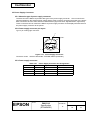
Customer Display
DM-D110
Specification
STANDARD
Rev. No.
G
Notes
Copied Date
,
,
Copied by
SEIKO EPSON CORPORATION
MATSUMOTO MINAMI PLANT
2070 KOTOBUKI KOAKA, MATSUMOTO-SHI, NAGANO, 399-8702 JAPAN
PHONE(0263)86-5353 FAX(0263)86-9925
Confidential
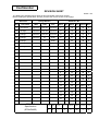
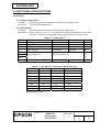
REVISION SHEET
Sheet 1 of 3
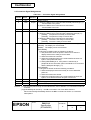
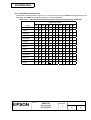
The table below indicates which pages in this specification have been revised.
Before reading this specification, be sure you have the correct version of each page.
Revisions
Rev.
Document
Design Section
Sheet Rev. No.
WRT
CHK
APL
Sheet
Rev. Sheet Rev.
Sheet
Rev.
A
Enactment
Takahashi
Kitabayashi
Ogasawara
I
E
18
E
42
E
B
Change
Takahashi
Kitabayashi
Ogasawara
II
E
19
E
43
E
C
Change
Takahashi
Kitabayashi
Ogasawara
III
E
20
E
44
E
D
Change
Takahashi
Tanimoto
/Ito
Endo
IV
E
21
E
45
E
E
Change
Tanimoto
Ito
Endo
22
E
46
E
F
Change
Tanimoto
Ito
Miyagawa
23
E
47
E
G
Change
Tanimoto
Ito
Miyagawa
24
E
48
E
DM-D110
Specification
(STANDARD)
1
E
25
E
49
E
2
G
26
E
50
E
3
E
27
E
51
E
4
G
28
E
52
E
5
E
29
E
53
E
6
E
30
E
54
E
7
E
31
E
55
E
8
E
32
E
56
E
9
E
33
E
57
E
10
E
34
E
58
E
11
E
35
E
12
E
36
E
App.1
E
13
E
37
E
14
E
38
E
15
E
39
E
16
E
40
F
17
E
41
F
Contents
Appendix
Total
58
1
67
Cover
Rev.
Sheet
Scope
1
3
--
General
Table of
Descriptions Contents
2
2
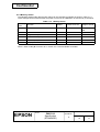
Confidential
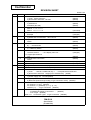
REVISION SHEET
Sheet 2 of 3
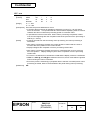
REV.
SHEET
B
3
4, 5
57
58
C
4, 5
8
D
II
III
6
13
E
17-1
17-2
All
2
3
4
6
7
10
CHANGED CONTENTS
1.7 Overall Specifications
1) Color Epson dark gray
(added)
2) Dimensions and mass DP-505
(added)
1.9 Options
7) Attachment
(added)
Illustration (DP-505)
(added)
<Function03> US ( E
Msw10 t = 0 → n = 0
Msw11 R = 0 → n = 0
(corrected)
<Function04> US ( E
Example
(changed)
1.9 Options
3) Stand and <Accessories> DP-110-1x2
(added)
3.1 Option Stand Connector
NOTE
(added)
GENERAL DESCRIPTION
8) ….. and IM series.
(added)
Table of contents
4.1.3 Memory Switch
(added)
2.1 Interface Connector
The base section ….. → The display main unit …
(changed)
2.2.1 Signal Specifications
(*2)
(added)
3.2.5 Stand-Alone Connection
(added)
NOTE
Sheet No. 17 → 17-1
(changed)
4.1.3 Memory Switch
(added)
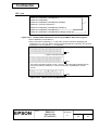
All page are renumbered due to a page deletion.
1.3 Electrical Specifications PS-180 (added)
1.7 Overall Specifications
1) Color …..and DP-110/DP-505 only → …..except DP-503 and DP-504
2) Dimensions and mass Height (in an extended use) (added)
1.9 Options
1) Power supply unit PS-180 (added)
2.2.1 Signal specifications
6) Baud rate (Pass through mode) (Y-type connection mode) (deleted)
Table 2.3.1 Connector Signal Assignments
Pin number 2: Y type (deleted)
Pin number 4: 1) (deleted), 2) → 1), 3) → 2)
NOTES: (*1): …..Y-type connection (deleted)
3.2.1 Connection diagram
….. or whether the printer is connected ….. (deleted)
….. or an Y-type (deleted)
Table 3.2.1 Connection Types Y-type connection (deleted)
TITLE
DM-D110
Specification
(STANDARD)
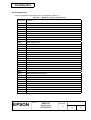
Confidential
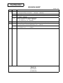
REVISION SHEET
Sheet 3 of 3
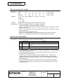
REV.
SHEET
E
11
12
13
F
40, 41
G
2
4
CHANGED CONTENTS
3.2.3 Pass through connection
The pas through connection….. example). (deleted)
3.2.4 Y-type connection (deleted)
3.2.5 → 3.2.4 Stand-alone connection Figure 3.2.4 → Figure 3.2.3
NOTE (deleted)
Table 3.3.1 Connector Signal Assignments
Pin number 2: or Y type (deleted)
Pin number 20: (*2) (deleted)
ESC = n [Notes] • With the pass through connection, ….. (added)
1.6 Safety and EMI Standards Applied
5) For others: Chinese EMC/Safety CCC
1.8 Accessories
2) Ferrite core ….. 1
(added)
TITLE
DM-D110
Specification
(STANDARD)
(added)
Confidential
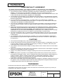
CONFIDENTIALITY AGREEMENT
BY USING THIS DOCUMENT, YOU AGREE TO ABIDE BY THE TERMS OF THIS AGREEMENT.
PLEASE RETURN THIS DOCUMENT IMMEDIATELY IF YOU DO NOT AGREE TO THESE TERMS.
1. This document contains confidential, proprietary information of Seiko Epson Corporation or its
affiliates. You must keep such information confidential. If the user is a business entity or
organization, you must limit disclosure to your employees, agents, and contractors who have a need
to know and who are also bound by obligations of confidentiality.
2. On the earlier of (a) termination of your relationship with Seiko Epson, or (b) Seiko Epson’s request,
you must stop using the confidential information. You must then return or destroy the information, as
directed by Seiko Epson.
3. If a court, arbitrator, government agency, or the like orders you to disclose any confidential
information, you must immediately notify Seiko Epson. You agree to give Seiko Epson reasonable
cooperation and assistance in resisting disclosure.
4. You may use confidential information only for the purpose of operating or servicing the products to
which the document relates, unless you obtain the prior written consent of Seiko Epson for some
other use.
5. Seiko Epson warrants that it has the right to disclose the confidential information. SEIKO EPSON
MAKES NO OTHER WARRANTIES CONCERNING THE CONFIDENTIAL INFORMATION OR ANY
OTHER INFORMATION IN THE DOCUMENT, INCLUDING (WITHOUT LIMITATION) ANY
WARRANTY OF TITLE OR NON-INFRINGEMENT. Seiko Epson has no liability for loss or damage
arising from or relating to your use of or reliance on the information in the document.
6. You may not reproduce, store, or transmit the confidential information in any form or by any means
(electronic, mechanical, photocopying, recording, or otherwise) without the prior written permission
of Seiko Epson.
7. Your obligations under this Agreement are in addition to any other legal obligations. Seiko Epson
does not waive any right under this Agreement by failing to exercise it. The laws of Japan apply to
this Agreement.
CAUTIONS
1. This document shall apply only to the product(s) identified herein.
2. No part of this document may be reproduced, stored in a retrieval system, or transmitted in any form
or by any means, electronic, mechanical, photocopying, recording, or otherwise, without the prior
written permission of Seiko Epson Corporation.
3. The contents of this document are subject to change without notice. Please contact us for the latest
information.
4. While every precaution has been taken in the preparation of this document, Seiko Epson Corporation
assumes no responsibility for errors or omissions.
5. Neither is any liability assumed for damages resulting from the use of the information contained
herein.
6. Neither Seiko Epson Corporation nor its affiliates shall be liable to the purchaser of this product or
third parties for damages, losses, costs, or expenses incurred by the purchaser or third parties as a
result of: accident, misuse, or abuse of this product or unauthorized modifications, repairs, or
alterations to this product, or (excluding the U.S.) failure to strictly comply with Seiko Epson
Corporation's operating and maintenance instructions.
7. Seiko Epson Corporation shall not be liable against any damages or problems arising from the use of
any options or any consumable products other than those designated as Original EPSON Products
or EPSON Approved Products by Seiko Epson Corporation.
TRADEMARKS
EPSON® and ESC/POS® are registered trademarks of Seiko Epson Corporation.
General Notice: Other product and company names used herein are for identification purposes only and may be
trademarks of their respective companies.
TITLE
DM-D110
Specification
(STANDARD)
SHEET
REVISION
E
NO.
NEXT
SHEET
II
I
Confidential
GENERAL DESCRIPTION
1. Application
These specifications apply to the DM-D110 customer display.
2. Features
1) Various expressions can be displayed on the 20-column by 2-line dot matrix.
2) The vacuum fluorescent display provides a wide viewing angle, long life, high reliability, and
high display quality.
3) The green fluorescent color is easy on the eyes.
4) The display panel is movable so that it can be adjusted for the best viewing angle (up, down,
right, and left.)
®
5) Control is based on the EPSON ESC/POS standard command set, which provides good
general utility and the following features:
• User-defined characters can be downloaded.
• Reverse characters can be specified.
• The specified display area can be controlled by the window function.
• International character sets are installed.
• The specified data can be displayed repeatedly by executing a macro.
• The brightness can be adjusted according to the ambient conditions.
• Memory switches that enable customizing are installed.
6) An interface based on EIA/TIA RS-232 is included, with baud rates from 2400 to 115200 bps.
(bps: bits per second)
7) Because a printer interface (based on RS-232) is included, it is possible to connect both a
printer and the display by preparing only one port for RS-232 on the host computer side.
8) The design matches EPSON printers (TM series) and IM series.
TITLE
DM-D110
Specification
(STANDARD)
SHEET
REVISION
E
NO.
NEXT
III
SHEET
II
Confidential
Table of Contents
1. GENERAL SPECIFICATIONS .............................................................................................................1
1.1 Display Specifications ....................................................................................................................1
1.2 Character Specifications ................................................................................................................1
1.3 Electrical Specifications .................................................................................................................2
1.4 Environmental Conditions ..............................................................................................................2
1.5 Reliability Specifications.................................................................................................................2
1.6 Safety and EMI Standards Applied ................................................................................................2
1.7 Overall Specifications ....................................................................................................................3
1.8 Accessories....................................................................................................................................4
1.9 Options...........................................................................................................................................4
2. INTERFACE .........................................................................................................................................6
2.1 Interface Connector .......................................................................................................................6
2.2 Interface Specifications..................................................................................................................6
2.2.1 Signal specifications ..............................................................................................................6
2.2.2 Communication Buffer size....................................................................................................6
2.3 Connector Signal Assignments......................................................................................................7
3. SPECIFICATIONS OF OPTION STAND .............................................................................................8
3.1 Option Stand Connector ................................................................................................................8
3.2 Option Stand Interface Specifications............................................................................................9
3.2.1 Connection diagram ..............................................................................................................9
3.2.2 Selection of the connection types ........................................................................................10
3.2.3 Pass through connection .....................................................................................................11
3.2.4 Stand-alone connection .......................................................................................................12
3.3 Host Interface...............................................................................................................................13
3.3.1 Host interface connector......................................................................................................13
3.3.2 Host interface connector signal assignments......................................................................13
3.4 Printer Interface ...........................................................................................................................14
3.4.1 Printer interface connector ..................................................................................................14
3.4.2 Printer interface connector signal assignments...................................................................14
3.5 Power Supply Connector .............................................................................................................15
3.5.1 About the type of power supply connector...........................................................................15
3.5.2 Power supply connector pin layout ......................................................................................15
3.5.3 Power supply connector ......................................................................................................15
4. FUNCTIONAL SPECIFICATIONS .....................................................................................................16
4.1 Switches.......................................................................................................................................16
4.1.1 Power supply switch ............................................................................................................16
4.1.2 DIP switches ........................................................................................................................16
4.1.3 Memory switch.....................................................................................................................17
4.2. Commands List...........................................................................................................................18
4.3 Character Code Tables................................................................................................................19
4.3.1 Page 0 (PC437: U.S.A., standard Europe) (international character set: U.S.A.).................19
4.3.2 Page 1 (Katakana)...............................................................................................................21
4.3.3 Page 2 (PC850: multilingual) ...............................................................................................22
4.3.4 Page 3 (PC860: Portuguese) ..............................................................................................23
4.3.5 Page 4 (PC863: Canadian-French) .....................................................................................24
4.3.6 Page 5 (PC865: Nordic) ......................................................................................................25
4.3.7 Page 16 (WPC1252) ...........................................................................................................26
4.3.8 Page 17 (PC866: Cyrillic2) ..................................................................................................27
4.3.9 Page 18 (PC852: Latin2) .....................................................................................................28
4.3.10 Page19 (PC858: Euro) ......................................................................................................29
4.3.11 Page254 (Space)...............................................................................................................30
TITLE
DM-D110
Specification
(STANDARD)
SHEET
REVISION
E
NO.
NEXT
SHEET
IV
III
Confidential
4.3.12 Page255 (Space)...............................................................................................................31
4.3.13 International character set .................................................................................................32
4.4 Self-test........................................................................................................................................33
4.4.1 Starting the self-test.............................................................................................................33
4.4.2 Ending the self-test ...........................................................................................................33
4.4.3 Contents of the self-test ....................................................................................................33
4.4.4 Notes.................................................................................................................................33
4.5 RAM Check..................................................................................................................................33
5. COMMAND DESCRIPTIONS.............................................................................................................34
5.1 Command Notation ......................................................................................................................34
5.2 Common Terms Used in the Command Descriptions .................................................................34
5.3 Defaults (Initial State at Power-On) .............................................................................................35
5.4 Command Details ........................................................................................................................36
BS.............................................................................................................................................36
HT.............................................................................................................................................36
LF .............................................................................................................................................37
US LF .......................................................................................................................................37
HOM .........................................................................................................................................38
CR ............................................................................................................................................38
US CR ......................................................................................................................................38
US B .........................................................................................................................................38
US $ n m ..................................................................................................................................39
CLR ..........................................................................................................................................39
CAN..........................................................................................................................................39
ESC = n ....................................................................................................................................40
ESC @ .....................................................................................................................................41
ESC % n...................................................................................................................................41
ESC & s n m [a [p]s x a] (m - n +1) ..........................................................................................41
ESC ? n ....................................................................................................................................43
ESC R n ...................................................................................................................................43
ESC t n .....................................................................................................................................44
ESC W n m (x1 y1 x2 y2).........................................................................................................44
US MD1....................................................................................................................................46
US MD2....................................................................................................................................46
US MD3....................................................................................................................................47
US C n......................................................................................................................................47
US E n ......................................................................................................................................47
US T h m ..................................................................................................................................48
US U.........................................................................................................................................48
US X n ......................................................................................................................................50
US r n .......................................................................................................................................50
US v n.......................................................................................................................................51
US @........................................................................................................................................51
US : ..........................................................................................................................................52
US ^ n m...................................................................................................................................53
US ^ n m...................................................................................................................................54
US ( A pL pH a [n m]1...[n m]k .................................................................................................55
US ( E pL pH n [parameter]......................................................................................................55
5.5 Ignored Commands .....................................................................................................................58
5.6 Unconditional Transmitted Commands........................................................................................58
APPENDIX. SIGNALS CONNECTION BETWEEN DM AND PC .................................................... App.1
TITLE
DM-D110
Specification
(STANDARD)
SHEET
REVISION
E
NO.
NEXT
SHEET
1
IV
Confidential
1. GENERAL SPECIFICATIONS
1.1 Display Specifications
1) Vacuum fluorescent display
40 (20 columns × 2 lines)
Green (505 nm)
2
690 cd/m
2) Number of characters:
3) Display color:
4) Brightness:
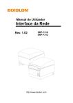
1.2 Character Specifications
1) Character type:
Alphanumeric:
International characters:
95
37
Graphic characters:
128 × 12 pages
2) Character font:
5 × 7 dot matrix, cursor
3) Character size:
3.5 mm {.14"} × 5.0 mm {.197"}
Refer to Figure 1.2.1 for details.
5.2mm {0.20"}
Refer to Figure 1.2.1 for details.
4) Character pitch:
Figure 1.2.1
DM-D110 Character Dimensions
TITLE
EPSON
DM-D110
Specification
(STANDARD)
SHEET
REVISION
E
NO.
NEXT
SHEET
2
1
Confidential
1.3 Electrical Specifications
1) Power supply types to be applied:
PS-170, PS-180, PA-6508, PB6509, PB-6510, PA-6511, PA-6513
(when the optional stand DP-110 is used)
11.4 - 48 VDC
0.2 A (max.)
2) Rated voltage:
3) Rated current:
1.4 Environmental Conditions
1) Temperature:
Operating:
5° to 40°C {41° to 104°F}
2) Humidity:
Storage:
Operating:
Storage:
-10° to 50°C {14° to 122°F}
30% to 85% (non-condensing)
30% to 90% (non-condensing)
3) Impact resistance:
When unpacked (with an optional stand):
Height:
5 cm {1.97"}
Directions:
4 sides; lift one edge and release it
No external or internal damage should be found after the drop test (performed when the unit is
not operating), and the unit should operate normally.
When packed:
Packing specifications: EPSON standard packing
Height:
90 cm {35.4"}
Directions:
1 corner, 3 edges, 6 faces
No external or internal damage should be found after the drop test, and the unit should operate
normally.
1.5 Reliability Specifications
1) MTBF:
20,000 hours (Vacuum fluorescent display only), a half-life period
1.6 Safety and EMI Standards Applied
1) Europe:
CE marking:
EN55022 class B
EN55024
Safety standard: EN60950
2) North America: EMI:
FCC class A / ICES-003 class A
Safety standard: UL1950 / CSA C22.2 No.950
3) Japan:
EMI:
VCCI Class A
JEIDA-52
4) Oceania:
EMC:
AS/NZS3548 (CISPR22) class B
5) For others:
Chinese EMC/Safety CCC
TITLE
EPSON
DM-D110
Specification
(STANDARD)
SHEET
REVISION
GE
NO.
NEXT
SHEET
3
2
Confidential
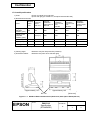
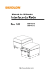
1.7 Overall Specifications
1) Color:
Epson cool white (for model-x0x)
Epson dark gray (for model-x1x, except DP-503 and DP-504)
2) Dimensions and mass
Optional
installation
base unit and
pole
Optional
installation
base unit and
pole
DP-503
DP-504
DP-505
260
248
129
260
318 (*1)
380
370
249
380
165
165
78
50
50
130
Depth (mm)
50.5
110
164
53
53
214
Mass (g)
285
385
264
116
60
418
Display
main
unit
Optional
stand
Height (in the
standard
position) (mm)
69
63
Height (in the
extended
position) (mm)
--
Width mm)
Items
Optional
installation
metal and pole
DP-110
DP-502
*1: When the extension pole DP-105 is used.
Optional
installation
metal and pole
(except the protrusion)
Maximum 48° (four steps and five positions)
4) Horizontal rotation:
Maximum 90° (each 45° to left and right)
Approximately 135
3) Viewing angle:
Approximately 165
Approximately 110
DP-110
Figure 1.7.1
DM-D110 External Dimensions (Reference) with Option Stand (DP-110)
TITLE
EPSON
[Units mm]
DM-D110
Specification
(STANDARD)
SHEET
REVISION
E
NO.
NEXT
SHEET
4
3
Confidential
1.8 Accessories
1) Installation manual:
2) Ferrite core:
For DM-D110 main unit .....1
1
1.9 Options
1) Power supply unit:
2) Pole unit:
3) Stand:
4) Installation metal:
5) Installation base unit:
6) Installation base unit:
7) Installation metal:
PS-170 / PS-180 (separately sold)
Refer to the PS-170 / PS-180 specification for detail.
DP-105 (separately sold)
Refer to the DP-105 specification for detail.
DP-110 (-1x1, -1x2)
DP-502
DP-503
DP-504
DP-505 (for TM-T88 series and TM-U210 series)
TITLE
EPSON
DM-D110
Specification
(STANDARD)
SHEET
REVISION
G
E
NO.
NEXT
SHEET
5
4
Confidential
<Accessories>
DP-110
-1x1
-1x2
DP-502
DP-503
DP-504
DP-505
Power extension cable
1
--
--
--
--
--
RS-232 connector fixing screw
(milli-type)
4
--
--
--
--
--
Fixing screw (tapping, M3 × 10)
--
--
2
3
--
--
Fixing screw (M3 × 5)
--
--
2
--
--
--
Fixing screw (M3.1 × 10)
--
--
4
--
--
5
Rubber foot (square type)
--
--
4
--
--
--
Velcro tape set
--
--
1
--
--
1
Rubber foot (large)
--
--
2
--
--
--
Fixing screw (M3 × 8)
--
--
--
--
3
--
Extension pole
--
--
1
1
1
1
Rubber foot (small)
--
--
4
--
--
--
Main plate
--
--
1
--
--
--
Main plate installation screw
--
--
4
--
--
--
Stopper
--
--
1
--
--
--
Stopper installation screw
--
--
1
--
--
--
DM view angle fixing screw
--
--
1
--
--
--
Installation plate, A
--
--
1
--
--
--
Installation manual
1
--
--
--
--
1
TITLE
EPSON
DM-D110
Specification
(STANDARD)
SHEET
REVISION
E
NO.
NEXT
SHEET
6
5
Confidential
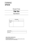
2. INTERFACE
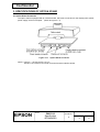
2.1 Interface Connector
The display main unit of the DM-D110 has an interface connector for connection to the DM-D stand and the
option to install the DM-D110 to IM series or TM series. (refer to Figure 2.1.1)
1
Figure 2.1.1
8
Interface Connector (Front)
2.2 Interface Specifications
2.2.1 Signal specifications
1) Specifications are based on EIA/TIA RS-232.
2) Data transmission method: Serial
3) Synchronization:
Synchronous
4) Handshaking (*1):
DTR/DSR control
5) Signal levels:
MARK = -3 to -15 V
logic = “1” OFF
SPACE = +3 to +15 V logic = “0” ON
6) Baud rate (*1):
2400, 4800, 9600, 19200, 38400, 57600, 115200 bps
(bps: bits per second)
7) Data word length (*1):
7 bits, 8 bits
8) Parity (*1):
None, odd, even
9) Stop bits:
1 or more
(*1) Selected by the DIP switches.
2.2.2 Communication Buffer size
80 bytes
TITLE
EPSON
DM-D110
Specification
(STANDARD)
SHEET
REVISION
E
NO.
NEXT
SHEET
7
6
Confidential
2.3 Connector Signal Assignments
Pin
Number
Signal
Name
Table 2.3.1 Connector Signal Assignments
Signal
Function
Direction
1
2
FG
TXD
Output
3
4
RXD
DSR
Input
Input
5
DTR
Output
6
7
8
SG
PS
PG
-
Frame ground
1) When the DM-D110 is connected with the data pass through (*1):
Transmit data to the printer
2) When the DM-D110 is connected in a stand-alone:
Transmit data to the host
Receive data from the printer
This indicates whether the printer is ready to receive data.
1) When the DM-D110 is connected with a data pass through (*1):
[MARK]: The printer is not ready to receive data
[SPACE]: The printer is ready to receive data
2) When the DM-D110 is connected in a stand-alone:
[MARK]: The host is not ready to receive data
[SPACE]: The host is ready to receive data
This indicates whether the display is ready to receive data (*2).
[SPACE] The display can receive data.
[MARK] The display cannot receive data.
[DTR MARK]
DTR goes to MARK under the following conditions:
➀ The period from when the power is turned on to when the
display first becomes ready to receive data.
➁ When the self-test is executed.
➂ When the remaining space in the receive buffer becomes 40
bytes or less (buffer-full state).
➃ When [DSR MARK] is on, if the printer is selected by a
peripheral device command. (When the DM-D110 is connected
with the data pass through.) (*1)
[DTR SPACE]
DTR goes to SPACE under the following conditions:
➀ When the display first becomes ready to receive data after
power-on.
➁ When the self-test has ended.
➂ When the remaining space in the receive buffer becomes 50
bytes or more after it became 40 bytes or less once.
Signal GND
Power supply terminal
Flyback line for power supply
NOTES: (*1) For the data pass through and the stand alone, refer to Section 3.2.1 Connection methods
for detail.
(*2) [DTR MARK] can be set by the US v command. This case differs from the
above-mentioned [DTR MARK]. Refer to the US v command in Section 4, Command
Descriptions.
TITLE
EPSON
DM-D110
Specification
(STANDARD)
SHEET
REVISION
E
NO.
NEXT
SHEET
8
7
Confidential
3. SPECIFICATIONS OF OPTION STAND
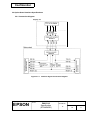
3.1 Option Stand Connector
The option stand is equipped with an interface board, which has connectors for the display panel, printer,
power supply, and host computer. (Refer to Figure 3.1.1)
Figure 3.1.1
Option Stand Connector
NOTE: Figure 3.1.1 shows the DP-110-1x1.
The DP-110-1x2 does not include connectors and the interface board.
TITLE
EPSON
DM-D110
Specification
(STANDARD)
SHEET
REVISION
E
NO.
NEXT
SHEET
9
8
Confidential
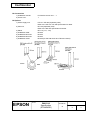
3.2 Option Stand Interface Specifications
3.2.1 Connection diagram
Figure 3.2.1
Interface Signal Connection Diagram
TITLE
EPSON
DM-D110
Specification
(STANDARD)
SHEET
REVISION
E
NO.
NEXT
SHEET
10
9
Confidential
Some functions depend on the device’s connection to the DM-D110, such as whether a printer is
connected or not, with a data pass through connection, or stand alone connection.
Connection type
Data pass through
(default setting)
Stand-alone connection
Table 3.2.1 Connection Types
JP2
Function
1-2
Can connect a printer which does not support the ESC =
command.
2-3
2-3
No printer is connected.
JP1
1-2
3.2.2 Selection of the connection types
Either the stand-alone connection or the data pass through connection can be selected with the setting of
the jumper JP1 and JP2 on the option stand.
TITLE
EPSON
DM-D110
Specification
(STANDARD)
SHEET
REVISION
E
NO.
NEXT
SHEET
11
10
Confidential
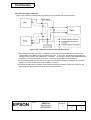
3.2.3 Pass through connection
Figure 3.2.2 shows the data flow when the DM-D110 is connected with the pass through.
Figure 3.2.2
Data Flow in a Pass Through Connection
1) With the pass through connection, the DM-D110 stores the transmitted data from the host in the
receive buffer of the DM-D110 and processes the data. In this case, the DM-D110 transmits only
the data for the printer to the printer that is connected. On the other hand, the transmitted data from
the printer is transmitted directly to the host, not through the mediation of the DM-D110.
2) The transmitted data from the host to the DM-D110 is identified whether it is data for the customer
display or the data for the printer with the ESC = command.
3) The data communication condition of the DM-D110 with the DIP switch such as the baud rate, the
data length, the parity must be same as the host and the printer.
TITLE
EPSON
DM-D110
Specification
(STANDARD)
SHEET
REVISION
E
NO.
NEXT
SHEET
12
11
Confidential
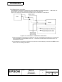
3.2.4 Stand-alone connection
The stand-alone connection is required to connect the DM-D110 without the printer. In this case, the
printer will be connected to another port than the one for the DM-D110.
Figure 3.2.3 shows the data flow when the DM-D110 is connected as a stand-alone.
Figure 3.2.3
Data Flow in a Stand-alone Connection
1) With the stand-alone connection, the data from the host is transmitted to the DM-D110, and the data
from the DM-D110 is transmitted to the host. Therefore, the status data of the DM-D110 can be
transmitted to the host.
2) The stand-alone connection is effective only when the customer display is selected with ESC = 2 and
either of the user setting commands.
TITLE
EPSON
DM-D110
Specification
(STANDARD)
SHEET
REVISION
E
NO.
NEXT
SHEET
13
12
Confidential
3.3 Host Interface
3.3.1 Host interface connector
The option stand provides the host interface connector (D-SUB 25 pin Female type) as shown in Figure
3.3.1.
25
14
1
13
Figure 3.3.1
Host Interface Connector
3.3.2 Host interface connector signal assignments
Table 3.3.1
Pin
Number
Signal
Name
Signal
Direction
1
2
FG
TXD
Output
3
4 (*1)
6 (*2)
RXD
RTS
DSR
Input
Output
Input
7
20 (*1)
GND
DTR
-Output
Connector Signal Assignments
Function
Frame ground
1) When the DM-D110 is connected with a pass through connection:
Transmit data to the host from the printer
2) When the DM-D110 is connected as a stand-alone:
Transmit data to the host from the DM
Receive data from the host (host → DM)
Same as DTR
Indicates whether the host is ready to receive data.
[SPACE] The host is ready to receive data.
[MARK] The host is not ready to receive data.
Signal ground
This indicates whether the display is ready to receive data.
[SPACE] The display can receive data.
[MARK] The display cannot receive data.
[DTR MARK]
DTR goes to MARK under the following conditions:
➀ The period from when the power is turned on to when the display first
becomes ready to receive data.
➁ When the self-test is executed.
➂ When the remaining space in the receive buffer becomes 40 bytes or
less (buffer-full state).
➃ When [DSR MARK] is on, if the printer is selected by a peripheral device
command.
[DTR SPACE]
DTR goes to SPACE under the following conditions:
➀ When the display first becomes ready to receive data after power-on.
➁ When the self-test has ended.
➂ When the remaining space in the receive buffer becomes 50 bytes or
more after it became 40 bytes or less once.
25
RESET
Input
Reset signal to the printer (host → printer)
NOTES (*1): Make sure to use either one of the RTS or the DTR terminal. Otherwise, the built-in
RS-232 driver IC may be broken.
TITLE
EPSON
DM-D110
Specification
(STANDARD)
SHEET
REVISION
E
NO.
NEXT
SHEET
14
13
Confidential
3.4 Printer Interface
3.4.1 Printer interface connector
The option stand provides the printer interface connector (D-SUB 9 pin Male type) as shown in Figure
3.4.1.
6
9
5
Figure 3.4.1
1
Printer Interface Connector
3.4.2 Printer interface connector signal assignments
Table 3.4.1
Pin
Number
Signal
Name
Signal
Direction
2
3
4
RXD
TXD
DTR
Input
Output
Output
5
6
GND
DSR
Input
9
RESET
Output
Connector Signal Assignments
Function
Receive data from the printer (printer → host)
Transmit data to the printer (DM → Printer)
Indicates whether the host is ready to receive data.
[SPACE] The host is ready to receive data.
[MARK] The host is not ready to receive data.
Signal GND
This indicates whether the display is ready to receive data from the
printer.
[SPACE] The printer can receive data. When the printer becomes
ready to receive data the SPACE is output.
[MARK] The printer cannot receive data. Even if the printer
becomes ready to receive data, the MARK is not output.
Reset signal to the printer (host → printer)
TITLE
EPSON
DM-D110
Specification
(STANDARD)
SHEET
REVISION
E
NO.
NEXT
SHEET
15
14
Confidential
3.5 Power Supply Connector
3.5.1 About the type of power supply connector
The base unit of the DM-D110 provides two types of the power supply connector. One is used for the
input terminals from the external power supply and the other is used for supplying the power to the printer.
Both connectors have the same electrical characteristics (signal functions, signal direction, signal level).
These connectors can be used for the DM-D110 power supply connector to the display interface board or
the power supply connector to the printer.
3.5.2 Power supply connector pin layout
Type: 3-pin locking type connector.
2
SHELL
3
Connector model:
1
Figure 3.5.1 Power Supply Connector
Interface board side: TCS7960-532010 (Hoshiden)
3.5.3 Power supply connector
Table 3.5.1 Power Supply Connector Pin Assignments
Pin Number
Signal Name Signal Direction Signal Function
1
+24V
-Power supply line
2
GND
-GND
3
NC
-Unused
SHELL
FG
-Frame GND
TITLE
EPSON
DM-D110
Specification
(STANDARD)
SHEET
REVISION
E
NO.
NEXT
SHEET
16
15
Confidential
4. FUNCTIONAL SPECIFICATIONS
4.1 Switches
4.1.1 Power supply switch
1) Feature:
2) Function:
A power supply switch is located on the bottom of the display panel.
Turns the power supply on/off.
4.1.2 DIP switches
1) Feature:
2) Functions:
Two DIP switches are located on the back of the display panel.
Refer to Tables 4.1.1 to 4.1.3. The DIP switch settings are read only when the power
is turned on. Therefore, changing the settings while the power is on has no effect.
Table 4.1.1
SW No.
1-1
Function
Data reception errors
DIP Switch 1
ON
Ignores
1-2
Data length
7 bits
8 bits
OFF
1-3
Parity check
Parity
No parity
OFF
1-4
Parity selection
Even parity
Odd parity
OFF
OFF
Displays “?”
Default
OFF
1-5
1-6
ON
Change baud rate
OFF
(Refer to Table 4.1.2)
ON
1-7
1-8
Self-test execution (*1)
Executes
Does not execute
OFF
(*1): When the power switch is turned on, the DM-D110 displays the continuous display pattern.
Table 4.1.2
SW1-5
ON
DIP Switch 1 Transmission Speed Switching
SW1-6
SW1-7
Baud Rate (bps)
ON
ON
2400
OFF
ON
ON
4800
ON
OFF
ON
9600
OFF
OFF
ON
19200
ON
ON
OFF
38400
OFF
ON
OFF
57600
ON
OFF
OFF
115200
OFF
OFF
OFF
(reserved)
(bps: bits per second)
TITLE
EPSON
DM-D110
Specification
(STANDARD)
SHEET
REVISION
E
NO.
NEXT
SHEET
17
16
Confidential
4.1.3 Memory switch
The following settings other than the DIP switch can be changed by software as shown in Table 4.1.3.
These settings become effective after the power is turned on or initialization is executed by a command.
Table 4.1.3
Memory
SW
Msw 10
Memory Switch
Function
Default
Content to be set
Range to be set
Character code table section
n=0
Page 0 is selected
0-5, 16-19, 254,
255
11
International character set selection
n=0
U.S.A. is selected.
0-13
12
Brightness adjustment
n=4
100 %
1-4
13
Selection of the peripheral devices
n=2
Display is selected
1-3
14
Cursor display
Selected
Selected
0, 1, 48, 49
15
Display No.
0
0
0-255
NOTE: Refer to US ( E <Function 03> in section 5.4 Command Details for details.
TITLE
EPSON
DM-D110
Specification
(STANDARD)
SHEET
REVISION
E
NO.
NEXT
SHEET
18
17
Confidential
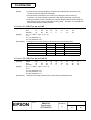
4.2. Commands List
Control commands for the DM-D110 are summarized in Table 4.2.1.
Table 4.2.1
DM-D110 Control Commands List
Command
Function
BS
HT
LF
US LF
HOM
CR
US CR
US B
US $
CLR
CAN
ESC =
ESC @
ESC %
ESC &
ESC ?
ESC R
ESC t
ESC W
US MD1
US MD2
US MD3
US C
US E
US T
US U
US X
US r
US v
US @
US :
US ^
US ( A
US ( E
Move cursor left
Move cursor right
Move cursor down
Move cursor up
Move cursor to home position
Move cursor to left-most position
Move cursor to right-most position
Move cursor to bottom position
Move cursor to specified position
Clear display screen
Clear cursor line
Select peripheral device(s)
Initialize display
Select/cancel user-defined character set
Define user-defined characters
Cancel user-defined characters
Select an international character set
Select character code table
Select/cancel window range
Specify overwrite mode
Specify vertical scroll mode
Specify horizontal scroll mode
Turn cursor display mode on/off
Set display screen blink interval
Set and display counter (time)
Display counter (time)
Brightness adjustment
Turn reverse mode on/off
Status confirmation by DTR signal
Execute self-test
Start/end macro definition
Execute macro
Select display(s)
User set-up commands
TITLE
EPSON
DM-D110
Specification
(STANDARD)
SHEET
REVISION
E
NO.
NEXT
SHEET
19
18
Confidential
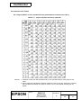
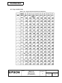
4.3 Character Code Tables
4.3.1 Page 0 (PC437: U.S.A., standard Europe) (international character set: U.S.A.)
Table 4.3.1
Page 0 Indicated characters (00H-7FH)
NOTES: 1. Character codes from 00H (hexadecimal) to 7FH (hexadecimal) for each page are the
same.
2. Some characters indicated by character codes from 00H to 7FH are changed by selecting
the international character set. Refer to Section 4.3.13, International character set, for
details.
TITLE
EPSON
DM-D110
Specification
(STANDARD)
SHEET
REVISION
E
NO.
NEXT
SHEET
20
19
Confidential
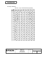
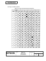
(Continued)
Table 4.3.2
Page 0 Indicated Characters (80H–FFH)
TITLE
EPSON
DM-D110
Specification
(STANDARD)
SHEET
REVISION
E
NO.
NEXT
SHEET
21
20
Confidential
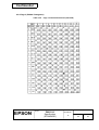
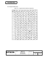
4.3.2 Page 1 (Katakana)
Table 4.3.3
Page 1 Indicated Characters (80H-FFH)
TITLE
EPSON
DM-D110
Specification
(STANDARD)
SHEET
REVISION
E
NO.
NEXT
SHEET
22
21
Confidential
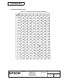
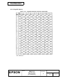
4.3.3 Page 2 (PC850: multilingual)
Table 4.3.4
Page 2 Indicated Characters (80H-FFH)
TITLE
EPSON
DM-D110
Specification
(STANDARD)
SHEET
REVISION
E
NO.
NEXT
SHEET
23
22
Confidential
4.3.4 Page 3 (PC860: Portuguese)
Table 4.3.5
Page 3 Indicated Characters (80H-FFH)
TITLE
EPSON
DM-D110
Specification
(STANDARD)
SHEET
REVISION
E
NO.
NEXT
SHEET
24
23
Confidential
4.3.5 Page 4 (PC863: Canadian-French)
Table 4.3.6
Page 4 Indicated Characters (80H-FFH)
TITLE
EPSON
DM-D110
Specification
(STANDARD)
SHEET
REVISION
E
NO.
NEXT
SHEET
25
24
Confidential
4.3.6 Page 5 (PC865: Nordic)
Table 4.3.7
Page 5 Indicated Characters (80H-FFH)
TITLE
EPSON
DM-D110
Specification
(STANDARD)
SHEET
REVISION
E
NO.
NEXT
SHEET
26
25
Confidential
4.3.7 Page 16 (WPC1252)
Table 4.3.8
Page16 Indicated Characters (80H−
−FFH)
TITLE
EPSON
DM-D110
Specification
(STANDARD)
SHEET
REVISION
E
NO.
NEXT
SHEET
27
26
Confidential
4.3.8 Page 17 (PC866: Cyrillic2)
Table 4.3.9
Page17 Indicated Characters (80H−
−FFH)
TITLE
EPSON
DM-D110
Specification
(STANDARD)
SHEET
REVISION
E
NO.
NEXT
SHEET
28
27
Confidential
4.3.9 Page 18 (PC852: Latin2)
Table 4.3.10
Page18 Indicated Characters (80H−
−FFH)
TITLE
EPSON
DM-D110
Specification
(STANDARD)
SHEET
REVISION
E
NO.
NEXT
SHEET
29
28
Confidential
4.3.10 Page19 (PC858: Euro)
Table 4.3.11
Page19 Indicated Characters (80H−
−FFH)
TITLE
EPSON
DM-D110
Specification
(STANDARD)
SHEET
REVISION
E
NO.
NEXT
SHEET
30
29
Confidential
4.3.11 Page254 (Space)
Table 4.3.12
Page254 Indicated Characters (80H−
−FFH)
UD: undefined
TITLE
EPSON
DM-D110
Specification
(STANDARD)
SHEET
REVISION
E
NO.
NEXT
SHEET
31
30
Confidential
4.3.12 Page255 (Space)
Table 4.3.13
Page255 Indicated Characters (80H−
−FFH)
UD: undefined
TITLE
EPSON
DM-D110
Specification
(STANDARD)
SHEET
REVISION
E
NO.
NEXT
SHEET
32
31
Confidential
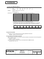
4.3.13 International character set
International characters listed in Table 4.3.14 can be changed by using the ESC R command. Refer to the
description of the ESC R command in Section 5.3, Command Details.
Table 4.3.14
International Character Set (Indicated Character Selection by Command)
ASCII code (Hex)
Country
23
24
40
5B
5C 5D
5E
60
7B
U.S.A
#
$
@
[
\
France
#
$
à
°
Germany
#
$
§
U.K.
£
$
Denmark I
#
Sweden
]
^
`
{
|
}
~
ç
§
^
`
é
ù
è
¨
Ä
Ö
Ü
^
`
ä
ö
ü
ß
@
[
\
]
^
`
{
|
}
~
$
@
Æ
Ø
Å
^
`
æ
ø
å
~
#
¤
É
Ä
Ö
Å
Ü
é
ä
ö
å
ü
Italy
#
$
@
°
\
é
^
ù
à
ò
è
ì
Spain I
Pt
$
@
¡
Ñ
¿
^
`
¨
ñ
}
~
Japan
#
$
@
[
¥
]
^
`
{
|
}
~
Norway
#
¤
É
Æ
Ø
Å
Ü
é
æ
ø
å
ü
Denmark II
#
$
É
Æ
Ø
Å
Ü
é
æ
ø
å
ü
Spain II
#
$
á
¡
Ñ
¿
é
`
í
ñ
ó
ú
Latin America
#
$
á
¡
Ñ
¿
é
ü
í
ñ
ó
ú
Korea
#
$
@
[
W
]
^
`
{
|
}
~
TITLE
EPSON
DM-D110
Specification
(STANDARD)
SHEET
REVISION
E
7C 7D
7E
NO.
NEXT
SHEET
33
32
Confidential
4.4 Self-test
4.4.1 Starting the self-test
There are two ways to start the self-test, as follows:
• Use US @ commands.
• Set the display to “Execute self-test” using DIP switch 1-8, and then turn on the power.
4.4.2
Ending the self-test
• After a series of self-tests is executed, the screen is cleared, the cursor is moved to the home
position, and the display goes into the standby state.
4.4.3
Contents of the self-test
The self-test shows the following:
• Control ROM version.
• DIP switch states.
• Memory switch settings
• Display characters.
• Functions.
4.4.4
Notes
1) During the self-test, only the self-test is processed; data is not processed.
➀ During the self-test, DTR (DM-D110 → host interface) goes to the MARK state.
➁ The DM-D110 does not receive data during the self-test.
➂ The DM-D110 does not transmit data to the printer.
2) Upon the completion of the self test by the US @ command, the following information and settings
are held:
➀ Contents of the receive buffer when receiving the self-test command and starting the self-test.
➁ Defined contents of user-defined characters.
➂ Defined contents of the macro processing program.
➃ Counter (time) settings.
4.5 RAM Check
When the power is turned on, the built-in RAM is checked. If an error is detected, the following occurs:
1) The error message is displayed.
2) The display does not operate (idle state) until the power is turned off.
TITLE
EPSON
DM-D110
Specification
(STANDARD)
SHEET
REVISION
E
NO.
NEXT
SHEET
34
33
Confidential
5. COMMAND DESCRIPTIONS
5.1 Command Notation
xxxx command
Describes the command headings.
[Name]
[Format]
The name of the command.
The code sequence.
ASCII indicates the ASCII equivalents.
Hex indicates the hexadecimal equivalents.
Decimal indicates the decimal equivalents.
[x]k indicates the contents of the [ ] should be repeated k times. In this case, x changes
in some commands.
[Range]
Gives the allowable ranges for the arguments.
[Description] Describes the function of command.
[Notes]
Provides important information on setting and using the display command, if necessary.
[Default]
Gives the default values (if any) for the command arguments.
[Reference] Lists related commands.
[Example]
Indicates the use of commands when opening a device file by assigning "#1" to the RS232 port when using Microsoft Basic.
5.2 Common Terms Used in the Command Descriptions
1) Cursor:
The cursor is located at the position on the screen where the next character will be written. The
position is indicated by the cursor.
2) Window:
The window is a general concept that specifies an area on the screen. Since the screen can be
divided into a maximum of four areas (windows) using a command, and since different modes can be
applied to each of them, each window behaves like a separate screen.
3) Current window:
The current window is the window that contains the cursor.
TITLE
EPSON
DM-D110
Specification
(STANDARD)
SHEET
REVISION
E
NO.
NEXT
SHEET
35
34
Confidential
5.3 Defaults (Initial State at Power-On)
The contents of the initial state are shown in Table 5.3.1 below.
Table 5.3.1
Initial State Setting Contents
Setting Items
Setting Contents
Display mode
Overwrite mode
Position
Home position (the upper left corner of the window)
Screen
Clear
Window
Not defined
Character code table
Page 0 (*1)
International character set
U.S.A. (*1)
User-defined characters
Not defined
Macro definition
Not defined
Reverse characters
Canceled
Display blinking
Canceled
Brightness adjustment
100% (*1)
Peripheral device selection
Display (*1)
Set-up time
00:00
Cursor display
Selected (*1)
(*1): Set by the memory switch.
TITLE
EPSON
DM-D110
Specification
(STANDARD)
SHEET
REVISION
E
NO.
NEXT
SHEET
36
35
Confidential
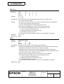
5.4 Command Details
BS
[Name]
[Format]
Move cursor left
ASCII
BS
Hex
08
Decimal
8
[Description] Moves the cursor one character position to the left.
[Notes]
[Reference]
• When the cursor is at the left end of a line, the operation of this command depends on
the display mode, as follows:
➀ Overwrite mode:
When the cursor is at the left end of the lower line, it is moved to the right end of
the upper line. When it is at the left end of the upper line, it is moved to the right
end of the lower line.
➁ Vertical scroll mode:
When the cursor is at the left end of the lower line, it is moved to the right end of
the upper line. When it is at the left end of the upper line, the display on the upper
line is scrolled to the lower line and the upper line is cleared. At this time, the is
cursor moved to the right end of the upper line.
➂ Horizontal scroll mode:
All characters on the current line are scrolled one character to the right. The cursor
is not moved, but the character area at the left end is cleared.
• When a window is defined, the cursor is moved only within the current window.
US MD1, US MD2, US MD3, ESC W
HT
[Name]
[Format]
Move cursor right
ASCII
HT
Hex
09
Decimal
9
[Description] Moves the cursor one character position to the right.
[Notes]
[Reference]
• When the cursor is at the right end of a line, the operation of this command depends
on the display mode, as follows:
➀ Overwrite mode:
When the cursor is at the right end of the upper line, it is moved to the left end of
the lower line. When it is at the right end of the lower line, it is moved to the left end
of the upper line.
➁ Vertical scroll mode:
When the cursor is at the right end of the upper line, it is moved to the left end of
the lower line. When it is at the right end of the lower line, the display on the lower
line is scrolled to the upper line and the lower line is cleared. At this time, the
cursor is moved to the left end of the lower line.
➂ Horizontal scroll mode:
All characters on the current line are scrolled one character to the left. The cursor
is not moved, but the character area at the left end is cleared.
• When a window is defined, the cursor is moved only within the current window.
US MD1, US MD2, US MD3, ESC W
TITLE
EPSON
DM-D110
Specification
(STANDARD)
SHEET
REVISION
E
NO.
NEXT
SHEET
37
36
Confidential
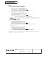
LF
[Name]
[Format]
Move cursor down
ASCII
LF
Hex
0A
Decimal
10
[Description] Moves the cursor down one line.
[Notes]
[Reference]
• When the cursor is on the lower line, the operation of this command depends on the
display mode, as follows:
➀ Overwrite mode:
The cursor is moved to the same column on the upper line.
➁ Vertical scroll mode:
The characters displayed on the lower line are scrolled to the upper line, and the
lower line is cleared. he cursor remains at the same position.
➂ Horizontal scroll mode:
The cursor is not moved.
• When a window is defined, the cursor is moved only within the current window.
US MD1, US MD2, US MD3, ESC W
US LF
[Name]
[Format]
Move cursor up
ASCII
US
LF
Hex
1F
0A
Decimal
31
10
[Description] Moves the cursor up one line.
[Notes]
[Reference]
• When the cursor is on the upper line, the operation of this command depends on the
display mode, as follows:
➀ Overwrite mode:
The cursor is moved to the same column on the lower line.
➁ Vertical scroll mode:
The characters displayed on the upper line are scrolled to the lower line, and the
upper line is cleared. The cursor remains at the same position.
➂ Horizontal scroll mode:
The cursor is not moved.
• When a window is defined, the cursor is moved only within the current window.
US MD1, US MD2, US MD3, ESC W
TITLE
EPSON
DM-D110
Specification
(STANDARD)
SHEET
REVISION
E
NO.
NEXT
SHEET
38
37
Confidential
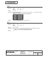
HOM
[Name]
[Format]
Move cursor to home position
ASCII
HOM
Hex
0B
Decimal
11
[Description] Moves the cursor to the left-most position on the upper line (home position).
[Note]
Home position indicates the first column of the upper line. When a window is defined, the
home position is the upper left corner of the window.
[Reference] ESC W
CR
[Name]
[Format]
Move cursor to left-most position
ASCII
CR
Hex
0D
Decimal
13
[Description] Moves the cursor to the left-most position on the current line.
[Note]
The cursor is moved only within the current window.
[Reference] ESC W
US CR
[Name]
[Format]
Move cursor to right-most position
ASCII
US
CR
Hex
1F
0D
Decimal
31
13
[Description] Moves the cursor to the right-most position on the current line.
[Note]
The cursor is moved only within the current window.
[Reference] ESC W
US B
[Name]
[Format]
Move cursor to bottom position
ASCII
US
B
Hex
1F
42
Decimal
31
66
[Description] Moves the cursor to the bottom position.
[Note]
The bottom position indicates the 20th column of the lower line. When a window is
defined, the bottom position is the lower right corner of the window.
[Reference] ESC W
TITLE
EPSON
DM-D110
Specification
(STANDARD)
SHEET
REVISION
E
NO.
NEXT
SHEET
39
38
Confidential
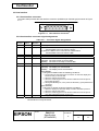
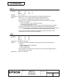
US $ n m
[Name]
[Format]
Move cursor to specified position
ASCII
US
$
n
Hex
1F
24
n
Decimal
31
36
n
m
m
m
1 ≤ n ≤ 20
m = 1 or 2
[Description] Moves the cursor to the nth column on the mth line.
[Note]
If a value exceeding the range is specified for n (column) and/or m (line), this command
is ignored and the cursor does not move.
[Range]
CLR
[Name]
[Format]
Clear display screen
ASCII
CLR
Hex
0C
Decimal
12
[Description] Clears all the displayed characters.
[Notes]
• After the command is executed, the cursor moves to the home position.
[Reference]
• When a window is defined, the cursor is moved only within the current window.
ESC W
CAN
[Name]
[Format]
Clear cursor line
ASCII
CAN
Hex
18
Decimal
24
[Description] Clears the line containing the cursor.
[Notes]
[Reference]
• After this command is executed, the cursor moves to the left-most position on the
current line.
• When a window is defined, the cursor is moved only within the current window.
ESC W
TITLE
EPSON
DM-D110
Specification
(STANDARD)
SHEET
REVISION
E
NO.
NEXT
SHEET
40
39
Confidential
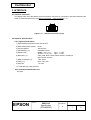
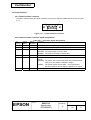
ESC = n
[Name]
[Format]
Select peripheral device
ASCII
ESC
=
Hex
1B
3D
Decimal
27
61
n
n
n
[Range]
1≤n≤3
[Description] Selects the device(s) to which the host computer sends data, using the value(s) of n
from the following table:
Table 4.4.1 Bit table for select peripheral device
Bit
Off/On
Hex
Decimal
Function
0
Off(*)
00
0
Printer canceled.
On
01
1
Printer selected.
1
Off
00
0
Display canceled.
On(*)
02
2
Display selected.
2 to 7
---Undefined.
(*):Default setting
[Notes]
• When the printer is selected by n = 1, all the data from the host computer is
transmitted to the printer via the display.
• When the customer display is selected by n = 2, all the data from the host computer is
processed internally in the display, and no data is transmitted to the printer.
• When both the printer and customer display are selected by n = 3, all the data from the
host computer is processed internally in the display and is simultaneously transmitted
to the printer.
• If ESC = 2 is received when the printer is selected by n = 1 or n = 3, this command
sends 1BH (27) 3DH (61) 02H (2) to the printer and stops transmitting data to the
printer.
• If ESC = 1 is received when the customer display is selected by n = 2, this command
sends 1BH (27) 3DH (61) 01H (1) to the printer and starts transmitting data to the
printer.
• If ESC = 3 is received when the customer display is selected by n = 2, this command
sends 1BH (27) 3DH (61) 03H (3) to the printer and starts transmitting data to the
printer.
• If ESC = 2 is received again after selecting the display by n = 2, the three-byte data is
executed only inside the display, and nothing is sent to the printer.
[Default]
[Example]
• With the pass through connection, when the ESC = command is received while the
printer is selected with n = 1 or n = 3, if n following ESC = is not 1, 2, or 3, the display
unit sends the whole of the ESC = n to the printer directly.
n = 2 or the setting value by the memory switch 13
➀
PRINT #1;CHR$(&H1B);CHR$(&H3D);CHR$(&H1);
➁
PRINT #1,”SELECT PRINTER”;
➂
PRINT #1,CHR&(&H1B);CHR$(&H3D);CHR$(&H2);
➃
PRINT #1,”SELECT DISPLAY”;
Figure 5.4.1 Example Peripheral Device Selection Program
TITLE
EPSON
DM-D110
Specification
(STANDARD)
SHEET
REVISION
EF
NO.
NEXT
SHEET
41
40
Confidential
• Data in lines ➀ and ➂ is processed internally in the display and sent to the printer
simultaneously.
• Data in line ➁ is sent to the printer regardless of display execution.
• Data in line ➃ only appears on the display screen, and nothing is sent to the printer.
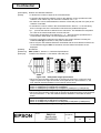
ESC @
[Name]
[Format]
Initialize display
ASCII
ESC
@
Hex
1B
40
Decimal
27
64
[Description] Resets the various display settings to their initial values.
[Notes]
• The software settings are reset to their power-on values.
• The DIP switches are not checked again.
• The data in the receive buffer is not cleared
[Reference]
• After initializing the display, the display screen is cleared and the cursor moves to the
home position.
Section 5.3, Defaults
ESC % n
[Name]
[Format]
Select/cancel user-defined character set
ASCII
ESC
%
n
Hex
1B
25
n
Decimal
27
37
n
[Range]
0 ≤ n ≤ 255
[Description] Selects or cancels the user-defined character set.
[Notes]
• When n is 1, the user-defined character set is selected. When the user-defined
character set is not defined using the ESC & command, the internal character set is
displayed.
• When n is 0, the user-defined character set is canceled. (The internal character set is
selected.) In this case, this command has no effect on the user-defined characters that
have already been defined using the ESC & command.
[Default]
[Reference]
• This command has no effect on the characters already displayed.
n=0
ESC &
ESC & s n m [a [p]s x a] (m - n +1)
[Name]
[Format]
[Range]
Define user-defined characters
ASCII
ESC
&
s
Hex
1B
26
s
Decimal
27
38
s
s=1
32 ≤ n ≤ m ≤ 126
0≤a≤5
0 ≤ p1 ... ps x a ≤ 255
n
n
n
TITLE
EPSON
DM-D110
Specification
(STANDARD)
m
m
m
[a [p] s x a] m - n + 1
[a [p1 p2 ...ps] x a] m - n + 1
[a [p] s x a] m - n + 1
SHEET
REVISION
EF
NO.
NEXT
SHEET
42
41
Confidential
[Description] Defines user-defined characters.
[Notes]
• s denotes the number of bytes in the vertical direction.
• n specifies the beginning character code for the definition, and m specifies the final
character code. When only one character is defined, use n = m.
• 95 characters can be defined between character codes 20H (32) and 7EH (126) in the
character code table.
• a denotes the number of dots in the horizontal direction. When a < 5, the remaining
dots on the right side of the user-defined characters are padded with spaces.
• p1 ... pk is the dot data to be defined for the characters. This indicates the dot pattern
for a dots in the horizontal direction from the left side.
• The number of data items to be defined is s × a. When 8 bits are specified for the
communication word length, the most significant bit is ignored.
• Once the user-defined characters are defined, they remain effective until they are
redefined, ESC @ is executed, or the power is turned off.
[Default]
[Reference]
[Example]
• When only the user-defined characters are defined and the user-defined character set
is not selected using the ESC % command, the user-defined characters are not
displayed.
Not defined.
ESC %, ESC ?, Section 1.2, Character Specifications
To define the character "" at character code 20H (32):
Figure 5.4.2 Example Bit image Specification
• When the communication word length is specified as seven bits, or when the word
length is specified as eight bits and the most significant bit is processed as “0,” the
user- defined character definition is executed as shown below:
PRINT #1 CHR$(&H1B);CHR$(&H26);CHR$(&H1);
PRINT #1 CHR$(&H20);CHR$(&H20);CHR$(&H5);
PRINT #1 CHR$(&H20);CHR$(&H41);CHR$(&H3F);CHR$(&H41);CHR$(&H20);
Figure 5.4.3 Example Bit image Specification
• When the communication word length is specified as eight bits and the most significant
bit is processed as “1,” the user-defined character definition is executed as shown
below:
PRINT #1 CHR$(&H1B);CHR$(&H26);CHR$(&H1);
PRINT #1 CHR$(&H20);CHR$(&H20);CHR$(&H5);
PRINT #1 CHR$(&HA0);CHR$(&HC1);CHR$(&HBF);CHR$(&HC1);CHR$(&HA0);
Figure 5.4.4 Example Bit image Specification
TITLE
EPSON
DM-D110
Specification
(STANDARD)
SHEET
REVISION
E
NO.
NEXT
SHEET
43
42
Confidential
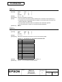
ESC ? n
[Name]
[Format]
Cancel user-defined characters
ASCII
ESC
?
n
Hex
1B
3F
n
Decimal
27
63
n
[Range]
32 ≤ n ≤ 126
[Description] Cancels user-defined characters.
[Notes]
• This command cancels the pattern defined for the character code specified by n.
• If specified code is transmitted after the pattern is canceled by this command, the
internal character is displayed.
• If the specified character code is not defined, this command is ignored.
[Reference]
• This command has no effect on characters already displayed.
ESC &
ESC R n
[Name]
[Format]
Select an international character set
ASCII
ESC
R
n
Hex
1B
52
n
Decimal
27
82
n
[Range]
0 ≤ n ≤13
[Description] Selects an international character set n from the following table:
Table 5.4.2 Parameters for international Character Set
n
Character Set
0
U.S.A.
1
France
2
Germany
3
U.K.
4
Denmark I
5
Sweden
6
Italy
7
Spain I
8
Japan
9
Norway
10
Denmark II
11
Spain II
12
Latin America
13
Korea
[Default]
[Reference]
n = 0 or the setting value by the memory switch 11.
Section 4.3.13, International Character Set
TITLE
EPSON
DM-D110
Specification
(STANDARD)
SHEET
REVISION
E
NO.
NEXT
SHEET
44
43
Confidential
ESC t n
[Name]
[Format]
Select character code table
ASCII
ESC
t
Hex
1B
74
Decimal
27
116
n
n
n
[Range]
0 ≤ n ≤ 5, 16, 17, 18, 19, 254, 255
[Description] Selects a page n from the character code table.
[Notes]
• This command has no effect on data displayed before this command is received.
[Default]
[Reference]
• This command has no effect on the selected international character set.
n = 0 (Page 0 is selected.) or the setting value by the memory switch 10.
Section 4.3, Character Code Tables
ESC W n m (x1 y1 x2 y2)
[Name]
[Format]
Select/cancel window range
ASCII
ESC
W
n
Hex
1B
57
n
Decimal
27
87
n
m
m
m
(x1 y1 x2 y2 )
(x1 y1 x2 y2 )
(x1 y1 x2 y2 )
1≤n≤4
m = 0, 1, 48, 49
1 ≤ x1 ≤ x2 ≤ 20
1 ≤ y1 ≤ y2 ≤ 2
[Description] Selects or cancels a single window on the display screen.
[Range]
[Notes]
• n specifies the window number to be selected or canceled.
• m specifies selection or cancellation.
When m = 1 or 49, a window is selected. (Values x1, y1, x2, and y2 are required.)
When m = 0 or 48, a window is canceled.(Values x1, y1, x2, and y2 are not required.)
• x1 and y1 set the positions of the upper left column and line of the window,
respectively.
• x2 and y2 set the positions of the lower right column and line of the window,
respectively.
• Up to four windows can be selected simultaneously on the display screen. However,
the window ranges cannot overlap.
• If a value outside the display screen or overlapping another window is set, this
command is ignored.
[Default]
• To cancel a window, arguments for the window range (x1, y1, x2, and y2) must not be
transmitted.
Not defined.
TITLE
EPSON
DM-D110
Specification
(STANDARD)
SHEET
REVISION
E
NO.
NEXT
SHEET
45
44
Confidential
Figure 5.4.5
Example Windows Specification Program
Figure 5.4.6
Figure 5.4.7
Windows Specification
Example Windows Internal Data Processing
TITLE
EPSON
DM-D110
Specification
(STANDARD)
SHEET
REVISION
E
NO.
NEXT
SHEET
46
45
Confidential
US MD1
[Name]
[Format]
Select overwrite mode
ASCII
US
MD1
Hex
1F
01
Decimal
31
1
[Description] Selects overwrite mode as the screen display mode.
[Notes]
• In overwrite mode, entering a character code moves the cursor to the left end of the
lower line when the cursor is at the right end of the upper line, and to the left end of the
upper line when the cursor is at the right end of the lower line.
• This mode is selected when the power is turned on.
• Selecting overwrite mode cancels horizontal or vertical scroll mode.
[Reference]
• Except when the cursor is at the right end, entering a character code moves the cursor
one character to the right after displaying the character.
US MD2, US MD3
US MD2
[Name]
[Format]
Select vertical scroll mode
ASCII
US
MD2
Hex
1F
02
Decimal
31
2
[Description] Selects vertical scroll mode as the screen display mode.
[Notes]
• In vertical scroll mode, entering a character code moves the cursor to the left end of
the lower line when the cursor is at the right end of the upper line, scrolls the
characters displayed on the lower line to the upper line, and clears the lower line when
the cursor is at the right end of the lower line.
At this time, the cursor is moved to the left end of the lower line.
• Selecting vertical scroll mode cancels overwrite or horizontal scroll mode.
[Reference]
• Except when the cursor is at the right end, entering a character code moves the cursor
one character to the right after displaying the character.
US MD1, US MD3
TITLE
EPSON
DM-D110
Specification
(STANDARD)
SHEET
REVISION
E
NO.
NEXT
SHEET
47
46
Confidential
US MD3
[Name]
[Format]
Select horizontal scroll mode
ASCII
US
MD3
Hex
1F
03
Decimal
31
3
[Description] Selects horizontal scroll mode as the screen display mode.
[Notes]
• In horizontal scroll mode, entering a character code scrolls all displayed characters
(including commas and periods) one character to the left, then displays the new
character at the right end (when the cursor is at the right end of either line.)
• Selecting horizontal scroll mode cancels overwrite or vertical scroll mode.
[Reference]
• Except when the cursor is at the right end, entering a character code moves the cursor
one character to the right after displaying the character.
US MD1, US MD2
US C n
[Name]
[Format]
Select/cancel cursor display
ASCII
US
C
n
Hex
1F
43
n
Decimal
31
67
n
[Range]
n = 0, 1, 48, 49
[Description] Selects or cancels the cursor display.
[Note]
[Default]
• When n = 1 or 49, the cursor display is selected.
• When n = 0 or 48, the cursor display is canceled.
This command does not affect the displayed data.
n = 1 or the setting value by the memory switch 14
US E n
[Name]
[Format]
Set display screen blink interval
ASCII
US
E
n
Hex
1F
45
n
Decimal
31
69
n
[Range]
0 ≤ n ≤ 255
[Description] Sets or cancels the blink interval of the display screen.
• n specifies the blink interval.
[(n × 50 ms.) ON / (n × 50 ms.) OFF] is repeated.
• When n = 0, the display is kept on (cancels blinking).
[Note]
[Default]
• When n = 255, the display is turned off but the contents of the display are maintained.
This command does not affect the brightness of the vacuum fluorescent display.
n=0
TITLE
EPSON
DM-D110
Specification
(STANDARD)
SHEET
REVISION
E
NO.
NEXT
SHEET
48
47
Confidential
US T h m
[Name]
[Format]
Set and display time counter
ASCII
US
T
h
Hex
1F
54
h
Decimal
31
84
h
m
m
m
0 ≤ h ≤ 23
0 ≤ m ≤ 59
[Description] The counter time is set and displayed at the right side of the bottom line.
[Range]
• h is hours, and m is minutes.
[Notes]
• When this command is entered, the screen is cleared and the time is displayed in
24-mode at the right side of the bottom line.
• The time counter starts from the transmitted code h:m:00.
• After the time is displayed, the cursor moves to the home position.
[Default]
[Reference]
• The counter display disappears when any of the following occurs:
1) The cursor moves to the bottom line.
2) Display characters move to the bottom line.
3) The CLR command is received.
• Even if the time counter is cleared, it continues to be updated in the display.
h = 0, m = 0
US U
US U
[Name]
[Format]
Display time counter
ASCII
US
U
Hex
1F
55
Decimal
31
85
[Description] Displays the time counter at the right side of the bottom line.
[Notes]
• If the time has already been set using the US T h m command, the elapsed time is
displayed in real time in the format “hours : minutes : seconds”.
• If the time has not yet been set, the elapsed time (from when the counter was
initialized by turning on the power or from the ESC @ command) is displayed in real
time in the format “ hours : minutes :seconds ".
• After the counter is displayed, the cursor moves to the home position.
[Reference]
• The counter display is cleared when any of the following occurs:
1) The cursor moves to the bottom line.
2) Display characters move to the bottom line.
3) The CLR command is received.
• Even if the time counter is cleared, it continues to be updated in the display.
US T
TITLE
EPSON
DM-D110
Specification
(STANDARD)
SHEET
REVISION
E
NO.
NEXT
SHEET
49
48
Confidential
[Example]
1) Counter display just before receiving UST h m:
Figure 5.4.8
[ :OFF]
Example Display Before Setting the Counter
2) US T h m(1FH(31)54H(84)14 15)is received:
Figure 5.4.9
[ :OFF]
Example Counter Setting Indication
screen (Figure 5.4.8) is cleared, and the input time is displayed at the right side of the lower line;
counting begins from 14:15:00 seconds. At this time, the cursor moves to the home position
indicated by .
3) Display data (“ABC”) is received:
Figure 5.4.10
[ :OFF]
Example Indication When the Cursor Does Not Move
counter display in the bottom line has no effect on data displayed in the top line.
4) LF(10H(16)) is received:
Figure 5.4.11
[ :OFF]
Example Indication When the Cursor Moves
Moving the cursor to the bottom line clears the time display, but counting continues internally.
(Figure 5.4.11 shows assumed overwrite mode.)
TITLE
EPSON
DM-D110
Specification
(STANDARD)
SHEET
REVISION
E
NO.
NEXT
SHEET
50
49
Confidential
US X n
[Name]
[Format]
Brightness adjustment
ASCII
US
X
Hex
1F
58
Decimal
31
88
n
n
n
[Range]
1≤n≤4
[Description] Sets the brightness of the fluorescent character display tube.
of brightness as follows:
Table 5.4.3 Parameters for Brightness Adjustment
n
Brightness
1
20%
2
40%
3
60%
4
100%
[Default]
n selects the percentage
n = 4 or the setting value by the memory switch 12
US r n
[Name]
[Format]
Select/cancel reverse characters
ASCII
US
r
n
Hex
1F
72
n
Decimal
31
114
n
[Range]
n = 0, 1, 48, 49
[Description] Selects or cancels reverse display of the characters received after this command.
• When n = 1 or 49, reverse characters are selected.
• When n = 0 or 48, reverse characters are canceled.
[Default]
n=0
TITLE
EPSON
DM-D110
Specification
(STANDARD)
SHEET
REVISION
E
NO.
NEXT
SHEET
51
50
Confidential
US v n
[Name]
[Format]
Status confirmation by DTR signal
ASCII
US
v
n
Hex
1F
76
n
Decimal
31
118
n
[Range]
n = 0, 1, 48, 49
[Description] Sets the DTR signal in the host interface to the MARK or SPACE state.
[Notes]
• When n = 1 or n = 49, the DTR signal goes to the MARK state.
If it is already in the MARK state, the DTR signal does not change.
• When n =0 or n = 48, the DTR signal goes to the SPACE state if the following
conditions are satisfied:
➀ The receive buffer is not in the buffer-full state.
➁ The self-test is not being executed.
If it is already SPACE when n = 0 is received, the DTR signal does not change.
• This command is effective only when the display alone is selected by ESC = 2.
Therefore, if the printer is already selected, this command (three bytes) is ignored and
is processed as normal data. (The data is transmitted to the printer.)
• If any data is received during status confirmation using the DTR signal, normal
interface timing control is executed immediately.
US @
[Name]
[Format]
Execute self-test
ASCII
US
@
Hex
1F
40
Decimal
31
64
[Description] Executes the self-test.
[Notes]
[Reference]
• A series of self-tests is displayed. All set values except those listed below are
initialized:
1) User-defined character definitions
2) Macro definitions
3) Time counter value
• After completion of the self-tests, the screen is cleared and the display position is
moved to the home position.
Section 4.4, Self-test
TITLE
EPSON
DM-D110
Specification
(STANDARD)
SHEET
REVISION
E
NO.
NEXT
SHEET
52
51
Confidential
US :
[Name]
[Format]
Start/end macro definition
ASCII
US
:
Hex
1F
3A
Decimal
31
58
[Description] Starts or ends a macro definition.
[Notes]
• Up to 80 bytes can be defined for macro processing (one byte per character).
• Macro definition processing starts with the first US : command and ends with the
second US : command.
[Reference]
[Example]
• Receipt of either of the two types of data shown below is regarded as a macro
definition error. Macro definition processing is stopped, and any following data is
processed as normal data. At this time, the macro remains undefined.
1) The US ^ command is received during a macro processing definition.
2) A macro processing definition exceeds 80 bytes (except for the US : command).
• To delete a macro definition, send a US : command just after US :.
US ^
➀
➁
➂
➃
➄
PRINT#1,CHR$(&H1F);CHR$(&H3A);
PRINT#1,CHR$(&HC);
PRINT#1,CHR$(&H1F);CHR$(&H45);CHR$(0);
PRINT#1,” Execution MACRO !!”;
PRINT#1,CHR$(&H1F);CHR$(&H45);CHR$(10);
PRINT#1,CHR$(&H1F);CHR$(&H3A);
Figure 5.4.12
Example Macro Definition Processing Program
• ➀ is the starting command and
is the ending command of a macro definition.
• The 26-byte data from ➁ to ➄ is stored in the macro definition range. When the display
receives the macro execution command, the defined data is in processed order. (Refer
to US ^.)
• ➁ is a screen clear command. (Refer to CLR.)
• ➂ and ➄ are blinking commands. (Refer to US E.)
TITLE
EPSON
DM-D110
Specification
(STANDARD)
SHEET
REVISION
E
NO.
NEXT
SHEET
53
52
Confidential
US ^ n m
[Name]
[Format]
Execute and quit macro
ASCII
US
^
Hex
1F
5E
Decimal
31
94
n
n
n
m
m
m
0 ≤ n ≤ 255
0 ≤ m ≤ 255
[Description] Executes the process defined as a macro.
[Range]
• n specifies the time interval for displaying characters in units of [n × 20 ms] when a
macro is executed. This specifies the time interval before displaying each successive
character but does not affect the processing speed of command codes.
• m specifies the interval of execution. Where macro processing is repeated, it starts
over from the beginning after the completion state of the previous macro processing is
held for [m × 50 ms].
[Notes]
• If data is received from the host during macro processing, the macro processing is
terminated.
• After macro processing is finished, the current window is cleared and the cursor is
moved to the home position in the current window.
• Display settings at the completion of macro processing remain valid.
• After macro processing is finished, the screen is cleared and the cursor is moved to
the home position. Display settings in place at the completion of macro processing
remain valid.
• If a macro is undefined, this command is invalid and the display content is not affected.
• If ESC = n, ESC @, and US @ are defined in the macro, these commands are ignored
when executing the macro commands.
[Reference]
• Even if the printer is selected (by a peripheral device selection command) when macro
processing is started, data is not transmitted to the printer during macro processing.
US :
TITLE
EPSON
DM-D110
Specification
(STANDARD)
SHEET
REVISION
E
NO.
NEXT
SHEET
54
53
Confidential
US ^ n m
[Example]
PRINT #1,CHR$(&H1F);CHR$(&H3A);
PRINT #1,CHR$(&HC);
➀
PRINT #1,CHR$(&H1F);CHR$(&H45);CHR$(0);
PRINT #1,” Execution MACRO !!”;
PRINT #1,CHR$(&H1F);CHR$(&H45);CHR$(10);
PRINT #1,CHR$(&H1F);CHR$(&H3A);
➁
PRINT #1,CHR$(&H1F);CHR$(&H5E);CHR$(5);CHR$(100);
Figure 5.4.13
Example Macro Definition Processing and Macro Execution Program
• Macro definition is executed by ➀.
• Macro execution is started by ➁. In this case, the time interval for displaying the
characters is (5 × 20 ms). When 100 ms has passed after the character “E” has been
displayed, the next character, “x”, is displayed.
[
OFF]
↓ (After a 100 ms interval)
[
OFF]
The macro execution interval is (100 × 50 ms). After the blinking display shown
in the figure below is held for 5 s, macro processing is repeated from a clear
screen.
[
Figure 5.4.14
Macro Processing Explanation
TITLE
EPSON
OFF]
DM-D110
Specification
(STANDARD)
SHEET
REVISION
E
NO.
NEXT
SHEET
55
54
Confidential
US ( A pL pH a [n m]1...[n m]k
[Name]
[Format]
Select displays(s)
ASCII
US
Hex
1F
Decimal
31
[Range]
3 ≤ (pL + pH × 256) ≤ 65535 (0 ≤ pL ≤ 255, 0 ≤ pH ≤ 255)
a = 48
n = 48, 49
0 ≤ m ≤ 255
1 ≤ k ≤ 32767
Display No.0 or the setting value of the memory switch 15.
[Default]
(
28
40
A
41
65
pL
pL
pL
pH
pH
pH
a
a
a
[n m]1...[n m]k
[n m]1...[n m]k
[n m]1...[n m]k
[Description] • Selects the displays to which host compute sends data.
• n specifies whether the display is enabled or disabled.
When n = 48, the display of the device number specified with m is disabled to receive
data from the host.
When n = 49, the display of the device number specified with m is enabled to receive
data from the host.
• m specifies the display device number.
When m = 0, all the displays are selected regardless of the previous-set value.
When m ≠ 0, the display of the device number specified with m is selected.
US ( E pL pH n [parameter]
[Name]
User setting commands
[Description] • Executes the process of the user setting commands.
n
Function No.
Function
1
Function 01 Changes into the user setting mode.
2
Function 02 Ends the user setting mode session. (Performs a software
reset.)
3
Function 03 Sets value(s) for the memory switch.
4
Function 04 Transmits the settings of the memory switch to the host.
• pL,
pH specifies (pL + (pH × 256)) as the number of bytes after pH (n and [parameter]).
specifies the function code.
• The customer display must be in the user setting mode before this command can
change values in the NV memory.
•n
• In Function 02, the customer display performs software reset. Therefore, the
customer display clears the receive buffer, and resets all settings (user-defined
characters, macros, the setting of window, and etc.,) and the display to the mode in
effect at power on.
• All customized values in the memory switch set by this command can be read by
Function 04 or the command, even though the customer display does not enter the
user-defined mode.
TITLE
EPSON
DM-D110
Specification
(STANDARD)
SHEET
REVISION
E
NO.
NEXT
SHEET
56
55
Confidential
[Notes]
• Only when the customer display is connected as a stand-alone, the host PC can
receive the transmit data from the display.
• Frequent write commands to NV memory may damage to the NV memory.
Therefore, it is recommended to write to the NV memory 50 times or less a day.
• During processing of this command, the customer display is BUSY while writing the
data to the NV user memory and stops receiving data. Therefore, it is prohibited to
transmit data while the display is BUSY.
<Function 01> US ( E pL pH n d1 d2
[Format]
[Range]
ASCII
US
(
E
Hex
1F
28
45
Decimal
31
40
69
(pL + pH × 256) = 3 (pL = 3, pH = 0)
n=1
d1 = 73 (Character “I”)
d2 = 78 (Character “N”)
pL
03
3
pH
00
0
n
01
1
d1
49
73
d2
4E
78
[Description] • Changes into the user setting mode and transmits the following data:
Transmitted data
➀ Header
➁ Flag
Display number
Separate code
➄ NUL
Hex
57H
23H
30 – 39H
1FH
00H
Decimal
87
35
48 – 57
31
0
Number of data
1 byte
1 byte
0 – 2 bytes
1 byte
1 byte
<Function 02> US ( E pL pH n d1 d2 d3
[Format]
[Range]
ASCII
US
(
E
pL
Hex
1F
28
45
04
Decimal
31
40
69
4
(pL + pH × 256) = 4 (pL = 4, pH = 0)
n=2
d1 = 79 (Character “O”)
d2 = 85 (Character "U")
d3 = 84 (Character "T")
pH
00
0
n
02
2
d1
4F
79
d2
55
85
d3
54
84
[Description] • Ends the user setting mode session and performs a software reset.
TITLE
EPSON
DM-D110
Specification
(STANDARD)
SHEET
REVISION
E
NO.
NEXT
SHEET
57
56
Confidential
<Function 03> US ( E pL pH n [a1 b18...b11]...[ak bk8...bk1]
[Format]
ASCII
Hex
Decimal
US
1F
31
(
28
40
E pL
45 pL
69 pL
pH
pH
pH
n
03
3
[a1 b18 ... b11] ... [ak bk8 ... bk1]
[a1 b18 ... b11] ... [ak bk8 ... bk1]
[a1 b18 ... b11] ... [ak bk8 ... bk1]
10 ≤ (pL + pH × 256) ≤ 65530
(where (pL + pH ×256) = 9 × k + 1: 0 ≤ pL ≤ 255, 0 ≤ pH ≤255)
n=3
a = 10 through 15
b = 48, 49, 50
1 ≤ k ≤ 7281
[Default at factory]
Refer to the following table for the setting of the memory switch.
[Range]
[Description] • Change the memory switch specified by a to the values specified with b.
• When b = 48, the applicable bit is turned to Off.
• When b = 49, the applicable bit is turned to On.
• When b = 50, the applicable bit is not changed.
• The specific value corresponds some of bits in bit 8 (MSB) to bit 1 (LSB)
Function
Item to be set
Memory
SW
Default
Setting range
Action when the
parameter is
specified out of range
Character code table
Page 0
MSW10
n=0
0-5, 16-19,
254, 255
Nothing to do
International
character set
U.S.A
MSW11
n=0
0-13
Nothing to do
Brightness
adjustment
100%
MSW12
n=4
1-4
Nothing to do
Peripheral device
selection
Display
MSW13
n=2
1-3
Nothing to do
Cursor display
Selected
MSW14
Specific
value
0, 1, 48, 49
Nothing to do
Display number
0
MSW15
0
0-255
TITLE
EPSON
DM-D110
Specification
(STANDARD)
SHEET
REVISION
E
NO.
NEXT
SHEET
58
57
Confidential
<Function 04> US ( E pL pH n a
[Format]
[Range]
ASCII
US
(
E
pL
Hex
1F
28
45
02
Decimal
31
40
69
2
( pL + pH × 256) = 2 (pL = 2, pH = 0)
n=4
a = 10 through 15
pH
00
0
n
04
4
a
a
a
[Description] • Transmits the setting value(s) of the memory switch specified by a.
Transmitted data
Hex
Decimal
Number of data
➀ Header
57H
87
1 byte
➁ Flag
24H
36
1 byte
Display number
30 – 39H
48 – 57
0 – 2 bytes
Separate code
1FH
31
1 byte
➄ Data
30 or 31H 48 or 49
8 bytes
➅ NUL
00H
0
1 byte
• Configuration of data as shown in ➄ is transmitted as 8 bytes.
The setting data in the memory switch [Off: Hex=30H / Decimal=48, On; Hex=31H /
Decimal=49] or a data string in the decreasing order from bit 8 to bit 1 as follows:
Example:
Switch
Msw10- Msw10- Msw10- Msw10- Msw10- Msw10- Msw10- Msw108
7
6
5
4
3
2
1
Status
OFF
OFF
OFF
ON
OFF
OFF
ON
ON
Transmit data for the memory settings above are 8 bytes of “00010011” (30H, 30H,
30H, 31H, 30H, 30H, 31H, 31H).
5.5 Ignored Commands
The DM-D110 customer display ignores the following ESC/POS commands:
US # n m (Specify on/off of annunciator)
5.6 Unconditional Transmitted Commands
When the DM-D110 receives the following command, the DM-D110 transmits the same data regardless
of the conditions of DSR.
DLE xx (real-time command)
Data is transmitted if the following codes are transmitted after the DLE command.
00H–08H, 10H, 12H, 14H
TITLE
EPSON
DM-D110
Specification
(STANDARD)
SHEET
REVISION
E
NO.
NEXT
App.1
59
SHEET
58
Confidential
APPENDIX. SIGNALS CONNECTION BETWEEN DM AND PC
Use a cable which connects signals as shown below using a DTR-DSR handshaking method between
the customer display and the host PC.
D-Sub 25P (DM-D)
D-Sub 9P (PC)
1.FG
1.DCD
2.TXD
2.RXD
3.RXD
3.TXD
4.RTS
4.DTR
5.CTS
5.SG
6.DSR
6.DSR
7.GND
7.RTS
20. DTR
8.CTS
25. RESET
9.RI
TITLE
EPSON
DM-D110
Specification
(STANDARD)
SHEET
REVISION
E
NO.
NEXT
END
60
SHEET
59
App.1