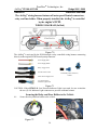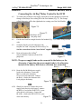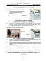
1
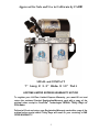
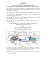
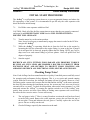
FP-100 & FP-150
INSTALLATION MANUAL
CUMMINS POWERED
DODGE TRUCKS
Model Year 2005 THROUGH 2009
High Performance Replacement Fuel System
For the 5.9L & 6.7L Engine
PLEASE READ THE INSTRUCTIONS THOROUGHLY
BEFORE BEGINNING INSTALLATION
1412 CREEK TRAIL DRIVE
JEFFERSON CITY, MO 65109
573 635-0555 VOICE
573 635-0778 FAX
www.pureflowtechnologies.com
CANADIAN PATENT
2,108,391
PROTECTED BY
US PATENTS
5,355,860; 5,746,184; 6,729,310
AUSTRALIAN PATENT
2005101054
NEW ZEALAND PATENT
532356
Additional Foreign Patents Pending in Europe, South America, Mexico, Japan, and China!
Approved for Sale and Use in California by CARB!
SMALL and COMPACT
7” Long X 3.2” Wide X 10” Tall
LIFETIME LIMITED EXPRESS WARRANTY NOTICE!
To register your LifeTime Limited Express Warranty, you must fill out and
return the enclosed Product Registration/Warranty card with a copy of the
original sales receipt to PureFlow® Technologies Within Thirty Days of
Purchase.
Failure to fill out and return your Registration/Warranty card with a copy of the
original sales receipt within Thirty Days will result in your receiving a ONE
YEAR WARRANTY!
2
OVERVIEW
Welcome to PureFlow® Technology’s AirDog®
Fuel Air Separation, Filtration and Delivery System for the Diesel Engine
The AirDog® Fuel Air Separation system is a Premium replacement lift pump
and filtration system for the Dodge Cummins diesel engine. A complete
installation kit is included.
The AirDog® delivers clean fuel to the engine free of virtually all air/vapor and
at a positive flow. Thus, allowing the engine “test cell” performance and
efficiency, while in “real world” use.
The AirDog® FP-100 flows 100 GPH and is recommended for stock and
slightly modified 5.9 L & 6.7L Cummins Diesels.
The AirDog® FP-150 is recommended for highly modified 5.9L & 6.7L
Cummins Diesels.
PureFlow products are manufactured with a personal touch,
unsurpassed attention to detail
and
the most stringent quality control!
TYPICAL INSTALLATION LAYOUT
Figure 1
The AirDog® draws fuel from the fuel tank at a constant flow, removing water, particulates,
and air/vapor. A regulated pressurized flow is maintained to meet the engine’s varying fuel
demands. The separated air/vapor is returned by the AirDog® to the fuel tank.
NOTE: The pictures used in this manual are for example only and may not be exactly the
same as your truck.
3
PureFlow® Technologies, Inc
AirDog® FP-100 & FP-150
Dodge 2005 - 2009
Table of Contents
Section 1
TABLE OF CONTENTS
Section 1……………………………….…………………..Table of Contents
Section 2…………………………...…….…Installation & Safety Guidelines
Section 3……………………………….…………………………….Parts List
INSTALLATION PROCEDURES
Section 4…………………….……………… AirDog® & Mounting Brackets
Fuel Lines
Section 5 A…………………………….……………….AirDog® To 5.9 CP-3
Section 5 B…………………………………..............AirDog® To 6.7L CP-3
Section 5 C……………………...……….………………Fuel Return to Tank
Section 5 D……………………….…..In-Tank Pump Bypass Suction Tube
Section 5 E……………………..………………………..…Fuel Suction Line
Electrical Harness
Section 6…..……………………………………………….Electrical Harness
Section 7..………….…………………….…………………..Final Check List
Maintenance
Section 8…………………………….……Filter Service Recommendations
Section 9…………………………………..….Pressure Regulator Changes
Section 10……………………..…………...Cleaning the Gerotor Assembly
Lifetime Limited Express Warranty
4
PureFlow® Technologies, Inc
AirDog® FP-100 & FP-150
Dodge 2005 - 2009
Installation & Safety Guidelines
Section 2
AirDog®
MODEL FP-100 & 150
The installation of your AirDog® can be made relatively easy by following the steps
outlined in this manual, and:
1.
Inventory the package components completely. Notify PUREFLOW®
TECHNOLOGIES, INC. immediately of any parts missing or damaged.
2.
Read the installation manual completely. Understand how the system
operates and installation recommendations before beginning installation.
3.
The installation recommendations contained herein are suggested
installation guidelines only. Individual installations may vary.
4.
If any installation procedure is uncertain, contact PUREFLOW®
TECHNOLOGIES, INC for technical assistance.
SAFETY GUIDELINES!
NOTE:
Proper location of the AirDog® on the vehicle is essential.
Consider hazards presented to the equipment by road debris
and the elements.
WARNING!
Please be sure to chock the vehicle’s tires to prevent rolling.
WARNING!
Please use proper supports when working beneath an elevated
vehicle.
WARNING!
Most diesel pickups have two (2) 12volt batteries. Disconnect
the battery cables to both batteries before proceeding with the
AirDog® installation.
IMPORTANT!
Use diesel fuel compatible thread sealer on all NPT tapered
pipe thread fuel fitting connections!
WARNING!
Vehicle frame rails should not be drilled into or welded upon.
CAUTION!
Wear safety glasses when operating power tools such as drills
and grinders or when using a punch or chisel.
CAUTION!
Use common sense when routing fuel lines and electrical
harnesses. Keep them away from hot exhaust components
and/or moving parts. Properly secure lines to prevent chaffing.
Use Good Judgment and Common Sense When Installing the AirDog®!
5
PureFlow® Technologies, Inc
AirDog® FP-100 & FP-150
Dodge 2005 - 2009
Parts List
Section 3
AirDog® Parts List
QTY
DESCRIPTION
1
Installation Manual
1
AirDog®
1
AirDog® Mounting Bracket
1
Mounting Bracket Hardware Kit, Includes:
Part Number
ADI-D0508P 100/150
FP-100-D24
Or
FP-150-D24
001-3C-0004
4ea Socket Head Cap Screws, 1/4-20 x 1-1/4" Lg.
4ea Lock Washers, 1/4”
4ea Hex Nuts, 1/4-20,
1
Frame Bracket
1
Frame Bracket Hardware Kit, Includes:
901-61-0101-PM
010-3C-0002PC
010-3C-0001PC
(Included In)
3ea 3/8” x 4-1/2” Hex Head Bolt,
3ea 3/8” Nut
3ea 3/8” Lock Washer
1
1
901-61-0101-PM
010-3C-0003A
Spacer
Spacer Bracket Hardware Kit, Includes:
4ea Bolts 5/16”x 2 ¾” L
4ea Washers
4ea Nuts
1
20 Ft.
(Included In)
901-61-0101-PM
5E-2-010
Wiring Harness
½” Fuel Line
4C-1-02-08-002
2
-8 JIC x 3/8” NPT
4A-1-02-08-06-S
4
-8 Swivel x ½” Push Lock
4A-1-09-08-08-B
1
-8 Swivel x-8 JIC Forged 90o
4A-2-04-08-08-S
2
-8 Swivel x ½” Push Lock 90o
4A-2-03-08-08-S
1
12mm x -8 JIC w/O-ring
001-4A-1-0002-S
1
Return Fuel Filler Tube Assembly (1-1/2” OD w/2 Clamps)
901-01-0103
1
Bundle of Plastic Ties
5H-2-1-06/12
1
Suction Tube Kit
901-01-0351-V
6
IMAGE
PureFlow® Technologies, Inc
AirDog® FP-100 & FP-150
Dodge 2005 - 2009
AirDog & Mounting Brackets
®
Section 4
Section 4: Installing the AirDog® & Mounting Brackets on
the Truck’s Frame!
Figure 2
4-1.
Figure 3
Assemble the AirDog® mounting bracket to the frame bracket.
Figure 4
4-2.
Figure 5
Use the aluminum spacer block to clear lines and wiring harnesses on the frame.
Adjust the assembly up or down on the frame bracket as necessary for clearance.
FUEL IN
4-3.
Install a 3/8” NPT x -8 JIC flare fitting
in the ‘FUEL IN’ and the out to ‘ENGINE’
ports in the AirDog®.
Figure 6
4-4.
Attach the AirDog® to the frame bracket assembly.
Figure 7
7
ENGINE
PureFlow® Technologies, Inc
AirDog® FP-100 & FP-150
Dodge 2005 - 2009
AirDog & Mounting Brackets
®
Section 4
Installing the AirDog® & Mounting Brackets on the Truck’s
Frame, cont’d!
NOTE: The AirDog® can be mounted on either the inside or the outside of the frame, as
space or personal choice dictates.
Mount
The AIRDOG®
Outside
The
Frame
Or
Figure 8
Figure 9
Inside
The
Frame
Figure 10
Figure 11
For this installation, the AirDog® is mounted inside the frame!
4-5.
Clamp the frame between the AirDog® bracket assembly and the backing plate using
the 3/8” x 4 ½” bolts, lock washers, and nuts included in the kit.
Figure 12
4-6.
Position the AirDog® on the frame as necessary for clearance. Properly torque all
fasteners!
NOTE: Be sure to mount the AirDog® so the ‘FUEL IN’ port is directed
toward the rear of the vehicle.
Figure 13A
Figure 13B
NOTE: Some pickup model frame rails have a bracket that is used to support the frame
during the manufacturing process If this bracket is on your frame rail and obstructs the
proper positioning of the AirDog® mounting bracket, you may remove part or all of it, as
needed. Be very careful not to damage the frame flange!
8
PureFlow® Technologies, Inc
AirDog® FP-100 & FP-150
Dodge 2005 - 2009
Fuel Lines
Section 5-A
Fuel Supply Line from the AirDog® to the CP-3
For the 5.9L Cummins Engine
The AirDog® fuel filter is made by Fleetguard and has a 2 micron Stratapore™ media.
When installing the AirDog® fuel system it is recommended to bypass the factory filter
canister.
5A-1. Remove the “banjo bolt” and the original factory fuel supply line at the fuel inlet port
of the CP-3 high pressure pump.
Figure 14
Figure 15
5A-2. Install the 12mm x -8 flare fitting with the O-ring supplied into the inlet port of the
CP-3 vacated by the original banjo fitting. Properly torque the 12mm x -8 flare fitting.
Caution: Do not over torque the 12mm fitting, IT COULD BREAK!
5A-3. Measure and cut the length of line required to connect the 'Fuel to Engine' port on the
AirDog® to the 12mm x -8 flare fuel inlet fitting on CP-3.
AirDog® Fuel Line to Engine
CP-3 Fuel Supply Line
Figure 16
Figure 17
5A-4. Install a 90o -8 Swivel x 1/2" Push Lock on the end of the fuel line to the engine and
a straight -8 Swivel x 1/2" Push Lock on the end to the AirDog®.
Figure 18
Figure 19
9
Figure 20
PureFlow® Technologies, Inc
AirDog® FP-100 & FP-150
Dodge 2005 - 2009
Fuel Lines
Section 5-A
Fuel Supply Line from the AirDog® to the CP-3
For the 5.9L Cummins Engine
5A-5. Connect one end of the fuel line to the
fitting on the AirDog® port marked
“ENGINE”. Properly torque the fitting.
To “ENGINE”
Figure 21
5A-6. Route and connect the other end of
the fuel line with the 90o fitting to the
fuel inlet fitting just installed on the
CP-3. When tightening the swivel,
use a back up wrench on the 12mm
fitting to preventing breaking it.
Figure 22
NOTE: It is NOT NECESSARY or recommended to keep the
factory filter canister in the system. This will cause additional
flow restriction to the CP-3. It is recommended to cap the
inlet port to the OE fuel pump and outlet port of the bypassed
filter canister.
Should you choose to keep the factory filter canister in the
system, it is recommended to install a ½” fuel line from
the filter canister to the CP-3. The optional Big Line Kit
is not included with this kit.
Figure 23
Section 5 B
Fuel Supply Line from the AirDog® to the CP-3
For the 6.7L Cummins Engine
The AirDog® fuel filter is made by Fleetguard and has a 2 micron Stratapore™ media.
When installing the AirDog® fuel system it is recommended to bypass the factory filter
canister.
5B-1. Remove the Quick Connect fitting and the
original factory fuel supply line at the fuel
inlet port of the CP-3 high pressure pump.
Figure 24
10
PureFlow® Technologies, Inc
AirDog® FP-100 & FP-150
Dodge 2005 - 2009
Fuel Lines
Section 5-B
Fuel Supply Line from the AirDog® to the CP-3
For Model Year 6.7L Engine, cont’d
5B-2. Install the 12mm x -8 flare fitting with the
O-ring supplied into the inlet port of the CP-3
vacated by the original Quick Connect fitting.
Properly torque the 12mm x -8 flare fitting.
Figure 25
Caution: Do not over torque the 12mm fitting, IT
COULD BREAK!
5B-3. Measure and cut the length of line required to connect the 'Fuel to Engine' port on the
AirDog® to the 12mm x -8 flare fuel inlet fitting on CP-3.
AirDog® Fuel Line to Engine
CP-3 Fuel Supply Line
Figure 26
Figure 27
5B-4. Install a straight -8 Swivel x 1/2" Push Lock on each end of the fuel line connecting
the engine to the AirDog®.
Figure 28
Figure 29
Figure 30
5B-5. Connect one end of the fuel line to the
fitting on the AirDog® port marked
“ENGINE”. Properly torque the fitting.
To “ENGINE”
Figure 31
11
PureFlow® Technologies, Inc
AirDog® FP-100 & FP-150
Dodge 2007.5 - 2009
Fuel Lines
Section 5-B
Fuel Supply Line from the AirDog® to the CP-3
For the 6.7L Cummins Engine
5B-6. Route and connect the other end of the
fuel line to the fuel inlet fitting just
installed on the CP-3. When tightening the
swivel, use a back up wrench on the 12mm
fitting to preventing breaking it.
Figure 32
NOTE: It is NOT NECESSARY or recommended to keep the
factory filter canister in the system. This will cause additional
flow restriction to the CP-3. It is recommended to cap the
outlet port of the bypassed filter canister.
Should you choose to keep the factory filter canister in the
system, it is recommended to install a ½” fuel line from
the filter canister to the CP-3. The optional Big Line Kit
is not included with this kit.
Figure 33
12
PureFlow® Technologies, Inc
AirDog® FP-100 & FP-150
Dodge 2005 - 2009
Fuel Lines
Section 5-C
Fuel Return Line from the AirDog® to the Tank
Installing the fuel 'Return to Tank' assembly in Filler Tube
Filler
Tube
Hose Clamp
Fuel Tank
Figure 34-A
Figure 35-A
5C-1. Cut filler tube as illustrated, removing 1½ inches. Loose assemble clamps on each
end of filler tube.
Filler
Tube
Hose Clamp
Fuel Tank
Figure 34-B
Figure 35-B
5C-2. Insert 'Return To Tank' assembly in filler tube rotate and position -8 flare fitting.
Properly tighten clamps.
Return Line to Tank
Figure 36
5C-3.
Measure and cut the length of fuel line necessary to connect the AirDog® to the
'Return to Tank' assembly in the filler tube.
13
PureFlow® Technologies, Inc
AirDog® FP-100 & FP-150
Dodge 2005 - 2009
Fuel Lines
Section 5-C
Fuel Return Line from the AirDog® to the Tank, cont’d
5C-4.
NOTE: For the 5.9L CP-3 installation install a straight 90o -8 swivel x 1/2" Push
Lock on the end of the fuel line connecting to the AirDog® return to tank.
NOTE: For the 6.7L CP-3 installation install a 90o -8 swivel x 1/2" Push Lock on
the end of the fuel line connecting to the AirDog® return to tank.
Lubricate the barb end of
the Push Lock fitting with oil.
Figure 37
Figure 38
Push the fuel line completely
onto the barb end of the fitting.
Figure 39
5C-5. Install a straight -8 swivel x 1/2" Push Lock on the end of the fuel line to the tank
return (Ref. Fig. 32)
5C-6
Install the forged 90o -8 swivel fitting on
the fitting in the AirDog® port marked
“TANK”.
Figure 40
5C-7. Connect the end of the fuel line with the
90O -8 swivel to the forged 90O fitting in
the AirDog® port marked “TANK”.
Figure 41
AirDog® Return to Tank
5C-8. Connect' the end with the -8 straight swivel
to the 'Return Filler Tube assembly.
Properly torque the fittings.
Figure 42
Filler Tube Fuel Return Assembly
14
PureFlow® Technologies, Inc
AirDog® FP-100 & FP-150
Dodge 2005 - 2009
Fuel Lines
Section 5-D
INSTALLING THE INTANK FUEL PUMP BYPASS SUCTION
TUBE!
NOTE: The AirDog® installation kit includes a Suction Tube to by pass the
“in-tank fuel pump on the 2005 - 2009 Dodge.
To install the suction tube it is necessary to either drop the fuel tank or to lift the truck bed.
NOTE: Should you choose to drop the fuel tank, support the tank as it is when it is installed
on the truck. If you let it rest flat on the floor, the tank may squash out and the suction tube
will be too short after the tank is re-installed in the truck. The suction tube, being cut too
short may suck air as the fuel drops below ¼ tank level.
NOTE: Should you choose to pull the pickup bed to access the tank. Be sure to disconnect
the tail light wires, fuel tank filler tube, and any other accessories or components that may be
secured to the frame and bed.
When Dropping the Tank, Always Remember Safety First!
Proper tools always make the job easier. The following pictures show using a transmission
jack to easily lower the fuel tank.
Figure 43
Figure 44
Figure 45
If you do not have access to a lift and transmission jack you may support
the truck on jack stands to drop the tank.
15
PureFlow® Technologies, Inc
AirDog® FP-100 & FP-150
Dodge 2005 - 2009
Fuel Lines
Section 5-D
INSTALLING THE SUCTION TUBE TO BYPASS THE INTANK FUEL
PUMP, Cont’d
If you choose to remove the bed, properly support the truck bed to prevent
serious injury or death!
Figure 46
Figure 47
IMPORTANT: Select a location for the suction tube that has adequate clearance
below the bed. Also consider that under hard acceleration, fuel will migrate
toward the back of the fuel tank.
NOTE: The fuel tank used for the pictures is for an example only and may not be exactly the
same as your tank.
5D-1. Remove the collection basket.
Figure 48
Figure 49
5D-2. Drill a 1-1/8” hole at the selected location in the fuel tank for the suction tube. Hold
a container below the drill point to catch debris.
Figure 50
Figure 51
16
PureFlow® Technologies, Inc
AirDog® FP-100 & FP-150
Dodge 2005 - 2009
Fuel Lines
Section 5-D
INSTALLING THE SUCTION TUBE TO BYPASS THE
INTANK FUEL PUMP, Cont’d
5D-3. Remove all burrs from the edge of the hole.
Figure 52
Figure 53
5D-4. Install the grommet in the new suction tube access hole.
5D-5. Assemble the suction tube and -8 flare x 3/8 NPT 900 fitting to the bulkhead fitting as
shown in Figure 52. Use diesel compatible thread sealer when assembling the NPT
fittings to the bulkhead fitting.
Figure 54
Figure 55
5D-6. Measure and cut the suction tube to a length that will allow approximately ¼”
clearance off the bottom of the tank. It is suggested to serrate the bottom of the
suction tube with notches approximately 1/8” deep to prevent possible blockage.
5D-7. Lubricate the bulkhead fitting with motor oil. Pressing firmly, insert the suction tube
assembly into the grommet. Be sure the bulkhead fitting is completely seated in the
grommet.
Figure 56
Figure 57
17
PureFlow® Technologies, Inc
AirDog® FP-100 & FP-150
Dodge 2005 - 2009
Fuel Lines
Section 5-D
The In-Tank Fuel Pump
VERY IMPORTANT: Before re-installing the collection basket, it is necessary to
disable the in tank fuel pump.
5D-8. You may either disconnect the power lead to the pump while
the collection basket is out of the tank and accessible……
Figure 58
OR
Locate and cut the power supply lead in the wire harness outside the tank
5D-9. Should you decide to disable the In Tank fuel pump by cutting the power lead
(Orange w/Red Stripe), you could just cut and insulate the wire (Fig 59) OR install
connectors to easily reconnect the pump later, if needed (Fig 60).
Figure 59
Figure 60
5D-10. Re-install the Collection Basket.
Figure 61
5D-11. Connect the AirDog® suction/supply line
to the suction tube while the top of the
fuel tank is easily accessible
Figure 62
If the fuel tank was dropped to install the suction tube, re-install the fuel
tank. If the truck bed was removed, reinstall the bed.
18
PureFlow® Technologies, Inc
AirDog® FP-100 & FP-150
Dodge 2005 - 2009
Fuel Lines
Section 5-E
Connecting the Fuel Supply Line from the AirDog® to the
Tank!
5D-1. Measure and cut the length of fuel line required to connect the fuel tank “SUCTION
TUBE” to the AirDog® fuel inlet port marked "Fuel In".
Figure 63
5E-2. Install a straight -8 JIC swivel x ½” Push Lock fitting on each end of the fuel suction
line to the fuel tank suction tube.
Lubricate the barb end of
the Push Lock fitting with oil.
Figure 64
Figure 65
Push the fuel line completely
onto the barb end of the fitting.
Figure 66
5E-3. Connect the straight -8 swivel to the AirDog® “Fuel In” fitting. Torque the fitting.
Figure 67
Figure 68
5E-4. Route the other end of the fuel suction line to the fuel tank suction tube.
NOTE: The AirDog® mounted on the frame with
all fuel lines attached!
Figure 69
19
PureFlow® Technologies, Inc
AirDog® FP-100 & FP-150
Dodge 2005 - 2009
Electrical Harness
Section 6
The AirDog® wiring harness features all water proof Deutsch connectors,
relay, and fuse holder. When properly installed, the AirDog® is controlled
by the engine’s ECM.
WIRING DIAGRAM (In Red)
Figure 70
®
The AirDog is activated by the ECM through a relay controlled wiring harness connecting
directly to the original ECM Deutsch pump connector.
Power Supply Red +
Power Supply Black Relay Trigger Lead
Pressure Sensor Lead
Motor Power Supply Lead
ECM Pump Lead Connectors,
Female
Low Fuel Pressure
Indicator Light Leads
Figure 71
CAUTION: If the OPTIONAL Low Pressure Indicator Light is not used, be sure to insulate
the two (2) #10 Indicator Light connectors to prevent accidental contact.
Securing the Relay and Fuse Holder to the Vehicle
6-1.
Secure the relay and fuse holder to the vehicle.
Figure 72
Figure 73
20
PureFlow® Technologies, Inc
AirDog® FP-100 & FP-150
Dodge 2005 - 2009
Electrical Harness, cont’d
Section 6
Connecting the AirDog® Relay Control to the ECM
6-2.
To connect the AirDog® relay trigger lead to the ECM fuel pump lead, locate the
Orange w/Red Stripe wire coming off of the Fuel Module (Fig. 75). The Orange
w/Red Stripe wire will be the right hand wire coming out of the Fuel Module.
Figure 74
Figure 75
Orange w/Red Stripe ECM
fuel pump lead!
6-2.
Cut the wire back far enough from the fuel module (Fig. 76) to make it easy to work
with.
6-3.
Crimp the female covered connector to the
Original “In-Tank” fuel pump ECM lead (Fig.76).
Seal the connection with the “heat Shrink” supplied.
Figure 76
Route and connect the AirDog®
relay lead (Male Connector) to the ECM
pump lead.
Figure 77
6-4.
NOTE: The power supply leads can be connected to the battery or the
alternator. Connecting the power supply leads to the alternator
instead of the battery will create a corrosion free connection.
Black (-)
6-5A. Route the Red & Black power supply
leads to the alternator. Connect the
Black (-) lead to the alternator
Chassis Ground connection. Connect
the Red (+) lead to the alternator Hot
Lead going to the battery.
Figure 78
OR
6-5B. Should you choose to connect the power
supply leads directly to the battery, connect
the RED (+) lead to the POSITIVE (+) post
of the driver's side battery. Connect the
BLACK (-) lead to the NEGATIVE (-) post
Figure 79
of the same battery.
21
Red (+)
PureFlow® Technologies, Inc
AirDog® FP-100 & FP-150
Dodge 2005 - 2009
Electrical Harness, cont’d
Section 6
Connecting the Wiring Harness to the AirDog®
6-5.
Route the wiring harness to the AirDog®
and connect the 2 pin Deutsch connector
to the corresponding connector on
the AirDog®.
Figure 80
INSTALLING THE OPTIONAL
LOW PRESSURE INDICATOR LIGHT
6-6.
Remove the 1/8” npt plug located in the top of the base below the end of the motor.
Screw the 45o adaptor fitting and pressure switch into this port and tighten. Connect
the two pin connector on the wiring harness to the pressure switch.
Optional Low Fuel Pressure Warning Light!
Figure 81
Figure 82
6-7.
Select a suitable location to install the Indicator Light!
Drill an 11/16" hole at that location. Drill a 5/8" hole in firewall to allow entry of the
Indicator Light harness into the passenger compartment.
6-8.
Route the Indicator Light harness through the firewall. Install the grommet supplied
with the kit around the wiring harness where it passes through the firewall to prevent
chaffing.
6-9.
Install the Indicator Light and Dash Plate in the location you chose. Install the
adhesive backed dash plate by removing the backing and matching the corresponding
dash plate hole with the 11/16" hole.
6-10. Properly assemble the Indicator Light in the dash plate. Connect the two connectors
on the wiring harness to the spade connectors on the indicator light.
BE SURE TO PROPERLY ROUTE AND SECURE THE WIRING HARNESS TO
THE VEHICLE.
22
PureFlow® Technologies, Inc
AirDog® FP-100 & FP-150
Dodge 2005 - 2009
Initial Startup Procedures
Section 7
INITIAL START PROCEDURE
The AirDog® is a self priming system, however, to prevent potential damage and reduce the
life expectancy of the system, it is recommended to pre-fill only the water separator with
diesel fuel before initial startup.
7-1.
Pre-fill the water separator with diesel fuel.
CAUTION: Check all of the fuel line connections to ensure that they are properly connected
and torque’d and BE ESPECIALLY SURE that the FUEL FILTER IS TIGHT to
PREVENT FUEL SPILLAGE!
7-2.
Turn the starter key to the on/run position.
Note: It may be necessary to momentarily engage the starter in order for the ECM to
energize the AirDog®.
7-3.
While the AirDog® is operating, bleed the air from the fuel line to the engine by
loosening the fuel line connection at the engine fitting. As soon as the line is purged
of air and pure fuel is observed, properly tighten the fuel fitting. NOTE: put a rag or
shop towel over and around fitting to prevent splatter. Catch all spilled fuel and
dispose of properly.
7-4.
Start the engine!
RECHECK ALL FUEL FITTINGS FOR LEAKAGE AND PROPERLY TORQUE.
BE SURE ALL FUEL LINES ARE PROPERLY ROUTED TO PROTECT FROM
EXCESSIVE HEAT AND SECURED TO PROTECT FROM CHAFFING AND
ABRASION. RECHECK ALL ELECTRICAL LINES, SECURE AS NECESSARY.
Checking Pump Noise!
Note: Each AirDog® has been manufactured in a Quality Controlled process and fully tested
for operation and performance before shipment. This is a very quiet and smooth running
system. With fuel or air alone, the AirDog® fuel pump will run very quietly. However, if any
fuel fitting on the vacuum side, between the fuel tank and the AirDog® or the water separator,
has been left loose during the installation process, the system may suck air at an excessive
rate and will be very noisy. To check for this problem, unscrew the water separator 3 or 4 full
turns and activate the AirDog® by turning the ignition switch to on. If the AirDog® runs
quietly, then excessive air from a loose fitting or leaking water separator seal is most likely
the reason for the excessive noise. Correct as necessary.
A.
The seal groove in the 3” filter is a snug fit and on occasion the seal has been found
to not be fully seated. Remove the water separator, remove the seal from the top of
the nut plate. Clean and lubricate the seal groove. Carefully replace the seal in the
groove. Be sure to fully seat the seal.
B.
Check all fittings, especially the connection at the tank.
23
PureFlow® Technologies, Inc
AirDog® FP-100 & FP-150
Dodge 2005 - 2009
Fuel Filter & Water Separator
Section 8
Filter Service Recommendations
Plugging of either the fuel filter or water separator will cause low fuel pressure and flow to
the engine. Should you experience low pressure, first check the water separator for plugging
and restriction. If the low fuel pressure issue continues, replace the fuel filter.
AirDog®
2 Micron Stratapore™
Fuel Filter
AirDog®
Wire Screen
Pre-filter
Drain Valve
Figure 83
The Pre-filter
The AirDog® wire screen water separator/pre-filter is serviceable and does not
need to be replaced as does the fuel filter. Replace the water separator only if it
should become damaged or defective. Servicing of the water separator simply
requires draining at regular intervals. It is suggested to check/drain the water
separator every three months or as needed should you experience excessive
‘water in fuel’ conditions. When re-installing the water separator, be sure to
clean the under side of the AirDog® base. Follow the instructions printed on the
water separator for proper tightening procedures.
Caution: Be extremely careful to prevent any contaminates or debris from
entering the water separator should it become necessary to remove it for
cleaning! Large debris will jam the Gerotor and cause the fuse to blow. This is
not a warranty item. Should this happen, it is easily put back into working
order. See the instructions on “How to R & R the Gerotor” for proper
procedures.
The Fuel Filter
Remove the fuel filter by turning it counter clockwise. Do Not pre-fill the fuel
filter with fuel. The AirDog® will fill the filter and prime the system
automatically. Follow the instructions on the filter for proper tightening
procedures.
CAUTION: Dispose of waste fuel and used filters properly to protect the environment!
24
PureFlow® Technologies, Inc
AirDog® FP-100 & FP-150
Dodge 2005 - 2009
Pressure Regulator Upgrade
Section 9
Changing the Regulator Spring
The AirDog® is shipped from the factory with the fuel pressure preset.
For the 2005-2009 Dodge Cummins the AirDog® fuel outlet pressure is preset at 15 PSI
(±2). However, for some applications, you may desire to increase the pressure output from
your AirDog®. To do this, you will need to install a higher tension spring.
Regulator Spring Replacement Procedure
The regulator spring and ball assembly is located inside the Return to
Tank fuel port.
Step-1. Disconnect the ‘Return to Tank’ fuel line.
Figure 9-1
Figure 9-2
Figure 9-3
Step-2. Remove the ‘Return to Tank’ fuel line fitting exposing the regulator spring.
Step-3. Remove the ball and spring.
Figure 9-4
Figure 9-5
Figure 9-6
Step-4. Install the new regulator spring by reversing the steps shown in Figures 9-1 through
9-6. Be sure to place the regulator ball in the regulator seat before inserting the
spring. Properly torque the return line fitting and swivel connection when finishing.
NOTE: Should any installation problems arise, please call, toll free 1-877-463-4373 or
573-635-0555, for assistance (Monday – Friday, 8:00 am – 5:00 pm CST).
25
PureFlow® Technologies, Inc
AirDog® FP-100 & FP-150
Dodge 2005 - 2009
AirDog® Fuel Pump
Section 10
Cleaning Foreign Debris from the Gerotor Assembly
Step 1
Remove the four (4) buttons
head cap crews that secure
the Gerotor cap.
Step 4
Clean the inside of the
Gerotor pocket.
Step 2
Step 3
Carefully remove the O-ring, Remove and clean the Gerotor.
you will need to re-use it.
Be very careful not to damage
the Gerotor.
Step 5
Replace the O-ring and
center gear.
Step 7
Install the Gerotor cap. Be very
careful to index the cap to position
the wide space between the half
moon cuts to the bottom.
Step 6
Align the teeth and
install the outer gear.
Step 8
Replace the cap into
position. Be very careful,
do not pinch the O-ring.
Torque the cap screws.
in an opposing pattern.
1.
4.
3.
2.
NOTE: Should any installation problems arise, please call, toll free 1-877-463-4373 or
573-635-0555, for assistance (Monday – Friday, 8:00 am – 5:00 pm CST).
26
27
Copyright © 2009
PureFlow Technologies, Inc.
All Right Reserved
PFT Bulletin No. ADI-D0507P-100/150
Printed 09
Revised March 3, 2009
28