1
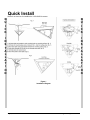
XX211-20
Quick Guide for
V15CCM-IR-2 Series Corner-Mounted
High-Security Cell Cameras
Copyright © 2010 Vicon Industries Inc. All rights reserved.
Product specifications subject to change without notice
Vicon and its logo are registered trademarks of Vicon Industries Inc.
Perspex is a registered trademark of Perspex South Africa (Pty).
Resistorx is a registered trademark of Acument Global Technologies.
Dyna-Poxy is a trademark of Pecora Corporation.
VICON INDUSTRIES INC., 89 ARKAY DRIVE, HAUPPAUGE, NEW YORK 11788
TEL: 631-952-CCTV (2288) FAX: 631-951-CCTV (2288) TOLL FREE: 800-645-9116
24-Hour Technical Support: 800-34-VICON (800-348-4266)
UK: 44 (0) 1489 566300 WEB: www.vicon-cctv.com
Vicon part number 8009-8211-20-00
Rev 610
FCC Notice
Note: Complies with Federal Communications Commission Rules & Regulations Part 15, Subpart B for a
Class A digital device.
WARNING
This equipment generates and uses radio frequency energy and if not installed and used properly, that is, in
strict accordance with the manufacturer’s instruction, may cause interference to radio and television
reception. It has been type tested and found to comply with the limits for a Class A computing device in
accordance with the specification in subpart B of part 15 of the FCC rules, which are designed to provide
reasonable protection against such interference in a commercial installation. However, there is no guarantee
that interference will not occur in a particular installation. If this equipment does cause interference to radio
and television reception, which can be determined by turning equipment off and on, the user is encouraged to
try and correct the interference by one or more of the following measures:
•
Reorient the receiving antenna.
•
Relocate the equipment with respect to the receiver.
•
Relocate the equipment away from the receiver.
•
Plug the equipment into a different electrical outlet so that the
equipment and receiver are on different branch circuits.
If necessary, the user should consult the dealer or an experienced radio/television technician for additional
suggestions.
The user may find the following booklet prepared by the Federal Communications Commission helpful:
“Interference Handbook, Bulletin CIB-2”
This booklet is available from the U.S. Government Printing Office, Superintendent of Documents, Mailstop
SSOP, Washington, D.C. 20402-9328, ISBN 0-16-045542-1.
Warning: Power must be removed from this unit before removing circuit modules or ribbon cables.
Caution: This unit contains circuit cards with integrated circuit devices that can be damaged by static
discharge. Take all necessary precautions to prevent static discharge.
XX211-20 Rev 610 V15CCM-IR-2 Series High-Security Cell Cameras
FCC Notice • iii
Important Safeguards – Indoor Use
GRAPHIC SYMBOL EXPLANATION
12. Lightning - Disconnect the product from its power source
The lightening bolt symbol alerts the user to the presence of
and cable system when possible to prevent damage due to
dangerous voltage that may present the risk of electric shock.
lightning and power-line surges.
13. Power Lines - Do not locate outside cables over power or
utility lines where they can fall and make direct contact. Contact
with power lines can be fatal.
14. Overloading - Do not overload wall outlets and extension
cords to prevent risk of fire and electric shock.
15. Object and Liquid Entry - Never probe through, or spill
liquid into, enclosure openings to prevent risk of fire or electric
shock.
16. Servicing - Refer all servicing to qualified service personnel.
The exclamation point symbol alerts the user to the presence of
17. Damage Requiring Service - Obtain service when:
a)
important operating and maintenance instructions.
b)
WARNING
The power-supply cord or plug is damaged.
Objects have fallen or liquid has been spilled into the
product.
To reduce a risk of fire or electric shock, do not
expose this product to rain or moisture.
1. Read Instructions - Read all safety and operating instructions
c)
The product is not designed for outdoor use and has been
exposed to water or moisture.
d)
The product does not operate per the operating instructions.
Perform Vicon recommended adjustments, modifications
before the product is operated.
and troubleshooting only to avoid unit damage and personal
2. Retain Instructions - Retain all safety and operating
injury.
instructions for future reference.
3. Heed Warnings - Pay attention to all product warnings.
e)
The product has been dropped.
4. Follow Instructions - Follow all operating instructions.
f)
The product shows a significant change in performance.
5. Cleaning -(Do not use caustic, abrasive or aerosol
18. Replacement Parts - Use only Vicon specified replacement
cleaners)
parts or an approved equivalent to prevent unit damage and
a)
For units that CAN BE DISCONNECTED from the power
injury.
source, use a damp cloth for cleaning.
19. Safety Check - Request safety checks to be performed
For units that CANNOT BE DISCONNECTED from the
following repair or maintenance to verify proper operation.
power source, use a damp cloth for cleaning and do not
20. ESD Precaution - Take all normal electrostatic discharge
allow moisture or liquids to enter vents.
precautions to avoid component damage during installation and
b)
6. Attachments - Use only UL Listed Vicon recommended
operation.
attachments to prevent unit damage and personal injury.
21. For 230 VAC Devices Only - When the disconnect device is
7. Water and Moisture - Use only products designed for outdoor
not incorporated in the equipment or when the plug on the power
environments where they will be exposed to water or moisture.
supply is intended to serve as the disconnect device, follow the
8. Accessories - Do not place the unit on an unstable surface to
guidelines below:
avoid falling. Use only UL Listed Vicon recommended mounting
a)
accessories.
site wiring.
9. Ventilation - Do not block ventilating slots and openings as
they ensure reliable operation. Do not place the unit near a heat
source or into an enclosure unless recommended by Vicon.
10. Grounding - Only products equipped with a 3-prong
grounded plug should be inserted into a grounded power outlet.
Contact an electrician to replace an obsolete outlet. Do not force
a plug into a non-grounded outlet.
11. Power Cord Protection - Power supply cords should not be
routed in trafficked areas or in tight spaces where they will be
pinched or used to bear weight. Allow some slack in the cord
where it enters the unit.
iv • Important Safeguards – Indoor Use
For permanently connected 230 VAC units, a readily
accessible disconnect device must be incorporated into the
b)
For 230 VAC units with a plug, the outlet must be installed
near the unit and be easily accessible.
21. Lithium Batteries Only:
WARNING
Fire and burn hazard. Do not recharge, disassemble,
heat above 212°F or incinerate. Keep battery out of
reach of children and in original package until ready
to use. Dispose of used batteries promptly.
Risk of explosion if battery is replaced by incorrect
type. Dispose of used batteries according to the
instructions.
XX211-20 Rev 610 V15CCM-IR-2 Series High-Security Cell Cameras
Introduction
The information in this manual provides quick installation and maintenance procedures for the V15CCM-IR-2
Series of High-Security Corner-Mounted Cell Cameras. These units should only be installed by a qualified
technician using approved materials in conformance with federal, state, and local codes. Read these
instructions thoroughly before beginning an installation. Refer to the complete manual, XX203, for details.
The V15CCM-IR-2 series is an integrated housing, camera, lens and IR illuminators system specifically
designed for use in custodial suites and prison cells. It is available in an analog version and two IP versions,
one that is fully compatible with all ViconNet® systems and an H.264 open-platform version. Refer to Table 1
for a list of model descriptions.
The housing is designed to fit into a corner; once installed, the base plate should be permanently sealed to
the wall so that the housing is ligature proof. The housing consists of a two part stainless steel assembly, a
fixed base plate and a removable front plate, that allows ease of installation and servicing. The front plate is
secured with Resistorx® torx screws and has two 10 mm Perspex® acrylic windows to protect the camera
and IR illuminators. The back of the front plate includes the camera/lens and all electronics. A secure access
plate covers the connectors for the keypad and monitor for setup.
The V15CCM-IR-2 series complies with FCC requirements for a Class A device and CE.
Model Number
V15CCM-IR-2/
V15CCM-IRP-2
V15CCM-IR-2IP/
V15CCM-IR-2IP-P
V15CCM-IR-2IP2/
V15CCM-IR-2IP2-P
Description
High-security indoor corner-mount camera; includes 1/3-in.
day/night camera, 2.5 mm lens, IR illuminators and a stainless
steel housing with adjustable mount; coaxial transmission;
NTSC/PAL
High-security indoor corner-mount camera; includes 1/3-in.
day/night camera, 2.5 mm lens, IR illuminators and a stainless
steel housing with adjustable mount; ViconNet IP transmission;
NTSC/PAL
High-security indoor corner-mount camera; includes 1/3-in.
day/night camera, 2.5 mm lens, IR illuminators and a stainless
steel housing with adjustable mount; open platform H.264
compression (IP); NTSC/PAL
Table 1: Models and Descriptions
XX211-20 Rev 610 V15CCM-IR-2 Series High-Security Cell Cameras
Introduction • 1
Quick Install
Below is an overview for installing the V15CCM-IR-2 camera.
Q
U
I
C
K
Q
U
I
C
K
I
N
S
T
A
L
L
A
T
I
O
N
I
N
S
T
A
L
L
A
T
I
O
N
Figure 1
Installation Diagram
2 • Quick Install
XX211-20 Rev 610 V15CCM-IR-2 Series High-Security Cell Cameras
Installation
The wall/ceiling material must provide suitable strength to support the weight of the unit (3.5 lb/1.6 kg). Be
sure the area around the selected location is clear of obstacles (such as steel beams, headers, pipes,
electrical wiring, etc.) that would interfere with mounting. All cables must be routed to the installation location.
Verify that the accessory pack contains the items listed in Table 2.
Item
No. 20 Torx Bit
No. 10 Torx Bit
2-Pin Terminal Block
Quick Guide/Documentation CD/
ViconNet CD (IP versions)
Quantity
1
Function
Use to remove and install tamperproof
screws from front plate
1
Use to remove and install tamperproof
screws from front plate access cover plate
1
Use to make power cable connections
1
Installation and operation instructions;
ViconNet setup CD
Table 2: Accessory Kit
Mounting the Housing
The housing consists of two main assemblies, the base plate and the removable front plate, where the
camera and all electronics are mounted. The front plate is secured to the base plate with Resistorx
tamperproof screws. A special bit is supplied in the accessory pack for removing and replacing these screws.
When the installation is complete, retain the Torx bit in case access to the interior of the housing is required
later. Refer to Figure 1 as needed.
1. Remove the front plate using the no. 20 Torx bit provided; retain the screws in a safe place. Using the
base plate as a template, mark the locations of the mounting holes on the three mounting tabs (2 holes
per tab). Open a hole in the wall or ceiling to accommodate routing the cables to the camera.
2. Route all necessary cables to the location if not already done so.
3. Drill suitable holes for the hardware selected appropriate for the wall/ceiling material. The use of No. 8 (or
4 mm metric) mounting hardware is recommended. Use hollow-wall anchors or, if the housing is being
mounted on a sheet metal surface, use rivet nuts.
4. Secure the base plate to the wall/ceiling with fasteners appropriate for the mounting surface. Route the
cables through the access hole in the wall or ceiling.
5. When the base plate is secured to the surface, apply an epoxy security sealant around the perimeter of
the base plate where it meets the ceiling/wall. [Vicon recommends DynaPoxy™ EP1200 (US) or Arbokol
1025 (UK) or equivalent for this purpose.]
XX211-20 Rev 610 V15CCM-IR-2 Series High-Security Cell Cameras
Installation • 3
Cable Connections
All cabling is done to the boards located on the back of the front plate.
Note: Vicon systems and components, like most electronic equipment, require a clean, stable power source.
Voltage irregularities such as surges, drops, and interruptions can affect the operation of your
equipment and, in severe cases, damage certain components.
Analog Cable Connections
1. Connect the power cable to the 2-postion terminal block TB1. The camera accepts 24 VAC and polarity is
not relevant.
2. Connect the coaxial cable for video output to the BNC connector (SK4).
3. To adjust the intensity of the LED illuminators, use RV1. Intensity can be adjusted over a range of
approximately 10:1 and is at maximum when RV1 is turned fully clockwise. The factory setting is for
maximum intensity.
IP Cable Connections
1. Use the RJ-45 connector if powering the camera using PoE. If using 24 VAC, connect the power cable to
the 2-postion terminal block.
2. Video and data are transmitted via the RJ-45 connector.
3. To adjust the intensity of the LED illuminators, use RV1. Intensity can be adjusted over a range of
approximately 10:1 and is at maximum when RV1 is turned fully clockwise. The factory setting is for
maximum intensity.
Final Installation
When all connections are made, secure the front plate to the base plate using the security screws previously
removed using no. 20 Torx bit.
Camera/Lens Positioning and Adjustments
The camera is on an adjustable mount so that it can be tilted slightly up and down to give a precise view. The
wide angle 2.5 mm lens enables the camera to view the area with no “blind spots.” Other camera/lens
adjustments are done through the OSD menu. The front plate includes a secure access plate that covers two
connectors, an RJ-45 and a BNC. The RJ-45 connector is used to connect a V15CC-PK hand-help keypad;
the BNC is connected to a monitor to view the programming menus.
1. Remove the two (2) screws securing the access plate with the no. 10 Torx bit.
2. Connect the keypad to the RJ-45 connector. Connect a monitor to the BNC and apply power to it.
3. On the keypad, press the SET key. The menu options display. Follow the menu system as described as
follows. Use the Up, Down, Right, Left keys to navigate the menus.
4 • Installation
XX211-20 Rev 610 V15CCM-IR-2 Series High-Security Cell Cameras
OSD Menu Map
1. E X P OS URE
6. P RIV A CY
LENS
MASK 1
E. SHUTTER
MASK 2
BLC
MASK 3
MAX_DR
MASK 4
AGC
MASK 5
SENSE_UP
MASK 6
2. COLOR
7. S Y NC
WB MODE
SYNC MODE
R-Y GAIN
V_PHASE
B-Y GAIN
3. DA Y & NIGHT
8. S E TUP
D&N MODE
CAMERA ID
C-SUP
TITLE
A-SUP
DPC
MONITOR
LANGUAGE
BAUDRATE
OMNI LENS
9. E X IT
4. FUNCT ION
MIRROR
EXIT
SHARPNESS
SAVE & EXIT
GAMMA
FACTORY SET
FREEZE
NEGA
3D_DNR
D_ZOOM
SLC
HME
DIS
5. M OT ION
MOTION
SET WINDOW
ALL SET
ALL CLEAR
SENSITI
SHOW INDI
DELAY OUT
Refer to the Installation manual for details on camera configuration.
Maintenance
The V15CCM-IR-2 requires no maintenance except the occasional cleaning of the housing and window. Use
a soft cloth and plain soap and water. Do not use abrasive cleansers that can scratch the window surface or
the finish on the housing.
XX211-20 Rev 610 V15CCM-IR-2 Series High-Security Cell Cameras
Maintenance • 5
Vicon Standard Equipment Warranty
Vicon Industries Inc. (the “Company”) warrants your equipment to be free from defects in material and workmanship under
Normal Use from the date of original retail purchase for a period of three years, with the following exceptions:
1.
2.
3.
4.
5.
6.
7.
8.
9.
VCRs, all models: Labor and video heads warranted for 120 days from date of original retail purchase. All other
parts warranted for one year from date of original retail purchase.
Video monitor CRT (cathode ray tube) and LCD monitors, all models: One year from date of original retail
purchase.
Uninterruptible Power Supplies: Two years from date of original retail purchase.
VDR-408 and VDR-416 Recorder Series: One year from date of original retail purchase.
V5616MUX: One year from date of original retail purchase.
S10-CH: 18 months from date of original retail purchase.
Normal Use excludes prolonged use of lens and pan-and-tilt motors, gear heads, and gears due to continuous
use of “autopan” or “tour” modes of operation. Such continuous operation is outside the scope of this warranty.
Vicon Security Management Systems (SMS) All Models: All hardware is warranted for two years from date of
original retail purchase.
Any product sold as “special” or not listed in Vicon’s commercial price list: One year from date of original retail
purchase.
Date of retail purchase is the date original end-user takes possession of the equipment, or, at the sole discretion of the
Company, the date the equipment first becomes operational by the original end-user.
The sole remedy under this Warranty is that defective equipment be repaired or (at the Company’s option) replaced, at
Company repair centers, provided the equipment has been authorized for return by the Company, and the return shipment
is prepaid in accordance with policy.
The Company will not be obligated to repair or replace equipment showing abuse or damage, or to parts which in the
judgment of the Company are not defective, or any equipment which may have been tampered with, altered, misused, or
been subject to unauthorized repair.
Software supplied either separately or in hardware is furnished on an “As Is” basis. Vicon does not warrant that
such software shall be error (bug) free. Software support via telephone, if provided at no cost, may be
discontinued at any time without notice at Vicon’s sole discretion. Vicon reserves the right to make changes to
its software in any of its products at any time and without notice.
This Warranty is in lieu of all other conditions and warranties express or implied as to the Goods, including any
warranty of merchantability or fitness and the remedy specified in this Warranty is in lieu of all other remedies
available to the Purchaser.
No one is authorized to assume any liability on behalf of the Company, or impose any obligations on it in connection with
the sale of any Goods, other than that which is specified above. In no event will the Company be liable for indirect, special,
incidental, consequential, or other damages, whether arising from interrupted equipment operation, loss of data,
replacement of equipment or software, costs or repairs undertaken by the Purchaser, or other causes.
This warranty applies to all sales made by the Company or its dealers and shall be governed by the laws of New York
State without regard to its conflict of laws principles. This Warranty shall be enforceable against the Company only in the
courts located in the State of New York.
The form of this Warranty is effective August 1, 2009.
THE TERMS OF THIS WARRANTY APPLY ONLY TO SALES MADE WHILE THIS WARRANTY IS IN EFFECT. THIS
WARRANTY SHALL BE OF NO EFFECT IF AT THE TIME OF SALE A DIFFERENT WARRANTY IS POSTED ON THE
COMPANY’S WEBSITE, WWW.VICON-CCTV.COM. IN THAT EVENT, THE TERMS OF THE POSTED WARRANTY
SHALL APPLY EXCLUSIVELY.
Vicon Part Number: 8006-9010-03-07 Rev 809
6 • Vicon Standard Equipment Warranty
XX211-20 Rev 610 V15CCM-IR-2 Series High-Security Cell Cameras
Notes
XX211-20 Rev 610 V15CCM-IR-2 Series High-Security Cell Cameras
Vicon Standard Equipment Warranty • 7
Vicon Industries Inc.
Corporate Headquarters
89 Arkay Drive
Hauppauge, New York 11788
631-952-CCTV (2288) 800-645-9116
Fax: 631-951-CCTV (2288)
Vicon Europe
Headquarters
Brunel Way
Fareham, PO15 5TX
United Kingdom
+44 (0) 1489 566300
Fax: +44 (0) 1489 566322
Vicon Germany
Kornstieg 3
D-24537 Neumuenster
Phone: +49 (0) 4321 8790
Fax: +49 (0) 4321 879 97
Far East Office
Unit 5, 17/F, Metropole Square
2 On Yiu Street, Shatin
New Territories,
Hong Kong
(852) 2145-7118
Fax: (852) 2145-7117
Internet Address: www.vicon-cctv.com