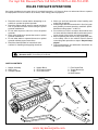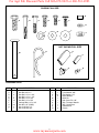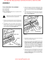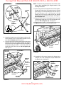
1
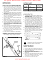
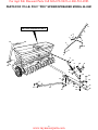
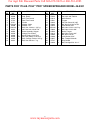
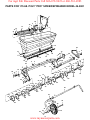
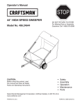
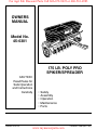
For Agri Fab Discount Parts Call 606-678-9623 or 606-561-4983
OWNERS
MANUAL
Model No.
45-0301
175 LB. POLY PRO
SPIKER/SPREADER
CAUTION:
Read Rules for
Safe Operation
and Instructions
Carefully
PRINTED IN U.S.A.
•
•
•
•
•
Safety
Assembly
Operation
Maintenance
Parts
www.mymowerparts.com
FORM NO. 47685 (REV. 3/01)
For Agri Fab Discount Parts Call 606-678-9623 or 606-561-4983
RULES FOR SAFE OPERATIONS
Any power equipment can cause injury if operated improperly or if the user does not understand how to operate
the equipment. Exercise caution at all times, when using power equipment.
• Wear eye and hand protection when handling and
using lawn chemicals.
• Always begin with the transmission in first (low) gear
and gradually increase speed as conditions permit.
Maximum towing speed - 10 M.P.H.
• Do not drive too close to a creek or ditch and be alert
for holes and other hazards which could cause you to
loose control of the tractor and spiker/spreader.
• Before operating the vehicle on any grade (hill) refer
to the safety rules in the vehicle owner's manual
concerning safe operation on slopes. Stay off steep
slopes!
• Follow maintenance and lubrication instructions as
outlined in this manual.
• Read this owner's manual before attempting to assemble or operate the spiker/spreader.
• Read the towing vehicle owner's manual and know
how to operate the tractor before using the spiker/
spreader attachment.
• Do not allow anyone to ride on or sit on the spiker/
spreader.
• Never allow children to operate the tractor or spiker/
spreader attachment.
• Do not allow adults to operate the tractor or spiker/
spreader without proper instructions.
• Read the chemical label for instructions and
cautions for handling and applying chemicals.
Look for this symbol to point out important safety precautions. It means--Attention!!
Become alert!! Your safety is involved.
CARTON CONTENTS
1. Hopper Assembly
2. Chain Cover
3. Transport Handle
4. Hopper Brace
5. Flow Control Gauge
6. Flow Control Arm
7. Flow Control Rod
8. Tongue Braces (2)
9. Tongue
10. Hitch Bracket
1
4
2
5
3
6
7
9
10
8
2
www.mymowerparts.com
For Agri Fab Discount Parts Call 606-678-9623 or 606-561-4983
SHOWN FULL SIZE
G
A
B
C
D
E
F
H
L
K
J
I
NOT SHOWN FULL SIZE
O
N
M
P
Q
HARDWARE CHART
REF. QTY.
A
B
C
D
E
F
G
H
I
1
2
1
2
16
1
20
4
1
REF. QTY.
DESCRIPTION
J
K
L
M
N
O
P
Q
R
Hex Bolt, 3/8" x 1"
Hex Bolt, 1/4" x 1-3/4"
Hex Bolt, 1/4" x 1-1/4"
Hex Bolt, 1/4" x 3/4"
Hex Bolt, 1/4" x 5/8"
Carriage Bolt, 1/4" x 3/4"
Hex Nut, 1/4" (SIMS)
Hex Lock Nut, 1/4"
Hex Lock Nut, 3/8"
3
1
10
3
1
1
1
1
1
2
DESCRIPTION
Lock Washer, 3/8"
Flat Washer, 1/4"
Nylon Washer
Hitch Pin
Hair Cotter Pin, 1/8"
Grip, Transport Handle
Grip, Control Arm
Plastic Knob
Ferrule
www.mymowerparts.com
R
For Agri Fab Discount Parts Call 606-678-9623 or 606-561-4983
ASSEMBLY
3. Attach the tongue to the frame assembly tube using
two 1/4" x 1-3/4" hex bolts, four 1/4" flat washers and
two 1/4" hex nuts as shown in figure 2. Do not tighten
yet.
TOOLS REQUIRED FOR ASSEMBLY
(2) 7/16" Wrenches
(2) 1/2" Wrenches
(2) 9/16" Wrenches
(2) 3/4" or Adjustable Wrenches (for optional wheel
removal in figure 5)
4. Attach the tongue to the two center braces using four
1/4" x 5/8" hex bolts and 1/4" hex nuts as shown in
figure 2. Do not tighten yet.
Spike points are sharp. Exercise caution when
working with hands near spike disks.
1/4" HEX NUT
1. Remove the hardware pack and all individual parts
from the carton and lay out as shown on pages 2 and
3.
1/4" FLAT
WASHER
2. Assemble the end of the tongue to the hopper as
shown in figure 1 using two 1/4" x 5/8" hex bolts and
1/4" hex nuts. The holes are located just below the
frame assembly tube. Do not tighten yet.
1/4" x 5/8"
HEX BOLT
1/4" x 5/8"
HEX BOLT
1/4" x 1-3/4"
HEX BOLT
1/4" HEX NUT
CENTER BRACE
FIGURE 2
FRAME ASSEMBLY TUBE
5. Assemble the plastic grip onto the end of the flow
control arm as shown in figure 3.
TONGUE
6. Insert the flow control arm through the slot in the
hopper brace. Place a nylon washer on each side of
the arm and attach it to the brace's welded bracket
using a 1/4" x 1-1/4" hex bolt, a 1/4" flat washer and two
1/4" hex lock nuts as shown in figure 3. Tighten the
first hex lock nut until there is noticeable resistance
when moving the flow control arm, then tighten the
second hex lock nut.
1/4" HEX NUT
FIGURE 1
7. Place the flow control rod through the hole at the end
of the flow control arm. Assemble the two ferrules
onto the threaded ends of the rod so that approximately 10 threads (1/2") of the rod extends through
the ferrules. See figure 3.
4
www.mymowerparts.com
For Agri Fab Discount Parts Call 606-678-9623 or 606-561-4983
NOTE: The wheels may be temporarily removed for easier
access when assembling the tongue braces in the
following instructions.
1/4" HEX
LOCK NUTS
1/4" x 1-1/4"
HEX BOLT
1/4" FLAT
WASHER
10. Insert a tongue brace through the slot in the end plate.
Fasten the front hole of the tongue brace to the end
plate using a 1/4" x 5/8" hex bolt and 1/4" hex nut. For
the rear hole use a 1/4" x 3/4" hex bolt, 1/4" flat
washer and 1/4" hex nut, with the bolt and washer
assembled from inside the poly hopper. See figure 5.
Do not tighten yet.
11. Fasten the other end of the tongue brace to the side
of the tongue using two 1/4" x 5/8" hex bolts and 1/4"
hex nuts. Do not tighten yet. See figure 5.
12. Repeat steps 10 and 11 for the second tongue brace.
13. Tighten all bolts and nuts assembled so far.
PLASTIC
GRIP
HOPPER
BRACE
NYLON
WASHER
FLOW
CONTROL
ROD
FLOW
CONTROL
ARM
1/4" FLAT
WASHER
1/4" x 3/4"
HEX BOLT
FERRULE
1/2"
1/4" HEX NUT
FIGURE 3
1/4" x 5/8"
HEX BOLT
8. Attach the hopper brace to the hopper using two 1/4"
x 5/8" hex bolts, one 1/4" flat washer and two 1/4" hex
nuts. Do not tighten yet. See figure 4.
9 Place the end of the hitch bracket with two holes down
through the slot in the tongue. Attach the hopper
brace to the top of the tongue and the hitch bracket to
the bottom using one 3/8" x 1" hex bolt, 3/8" lock
washer and 3/8" hex lock nut. Do not tighten yet.
See figure 4.
1/4" x 5/8"
HEX BOLT
1/4" HEX NUT
1/4" x 5/8"
HEX BOLT
1/4" HEX NUT
FIGURE 5
14. Assemble the flow control gauge to the hopper brace
using the 1/4" x 3/4" carriage bolt, a nylon washer and
the plastic knob. See figure 6.
HOPPER
BRACE
1/4" FLAT
WASHER
(ONE ONLY)
3/8" x 1"
HEX BOLT
NYLON
WASHER
HITCH
BRACKET
PLASTIC
KNOB
FLOW
CONTROL
GAUGE
3/8" LOCK
WASHER
3/8" HEX
LOCKNUT
1/4" x 3/4"
CARRIAGE BOLT
FIGURE 4
FIGURE 6
5
www.mymowerparts.com
For Agri Fab Discount Parts Call 606-678-9623 or 606-561-4983
15. Check that both ferrules are adjusted so that approximately ten threads (1/2") of the control rod is exposed.
Insert both ferrules into the brackets which are riveted to
the front of the flow plates. Assemble a 1/4" hex lock nut
onto each ferrule, making only finger tight at this time.
See figure 7.
18. Remove the two 5/16" lock washers and 5/16" hex nuts
from the carriage bolts which are pre-assembled to the
lift assembly arm. Attach the transport handle to the arm
using the lock washers and hex nuts which you removed. See figure 8.
19. Assemble the handle grip to the transport handle. See
figure 8.
HANDLE GRIP
1/4" HEX
LOCK NUT
FERRULE
TRANSPORT HANDLE
(2) 5/16" LOCK
WASHERS
(PREASSEMBLED)
(2) 5/16" x 1"
CARRIAGE BOLTS
(PREASSEMBLED)
(2) 5/16" HEX NUTS
(PREASSEMBLED)
BRACKET
FIGURE 7
FIGURE 8
16. To check for correct opening of hopper flow plates:
a. Set the flow control gauge at the highest setting.
b. Move the flow control arm away from the hopper until
it rests against the gauge. The slots in the bottom of
the hopper should now be completely open. The
edge of the flow plates should be just clear of the
ends all the slots.
c. If the flow plates are not straight with the slots, screw
one ferrule up or down on one side of the control rod.
d. If the flow plates open to far or not far enough, screw
both ferrules equally up or down on the control rod.
d. Move the flow control arm toward the hopper to the
off position. Verify that the slots in the bottom of the
hopper are completely covered by the flow plates.
e. Tighten the lock nuts and then loosen 1/4 turn.
20. Assemble the chain cover to the frame assembly using
two 1/4" x 5/8" hex bolts, 1/4" flat washers and 1/4" hex
nuts as shown figure 9.
21. Install the hitch pin and the 1/8" hair cotter pin in the
spreader hitch bracket and tongue. See figure 9.
1/4" FLAT
WASHER
1/4" HEX
LOCK NUT
CHAIN COVER
17. To check for proper tension on the hopper flow plates:
a. Set the flow control gauge at a mid range setting.
b. Move the flow control arm against the gauge.
c. Press firmly against the front of the flow plates at the
bottom of the hopper. The flow control arm should
not move.
d. If the arm moves, tighten the hex lock nuts on the flow
control arm until movement is prevented.
3/8" HITCH PIN
1/4" x 5/8"
HEX BOLT
FIGURE 9
6
www.mymowerparts.com
1/8" HAIR
COTTER PIN
For Agri Fab Discount Parts Call 606-678-9623 or 606-561-4983
SETTING CHART
OPERATION
HOW TO USE YOUR SPIKER/SPREADER
1. Refer to the instruction label on the material package and to the instruction decal on your spreader
to help determine the proper spreader setting and
application rate. Also see the Setting Chart on this
page for a general range of settings for commonly
used materials.
2. Loosen the knob and adjust the flow control gauge
to the recommended setting. Retighten the knob.
See figure 10.
3. Determine the approximate square footage of the
area to be covered and estimate the amount of
fertilizer or seed required.
4. Move the spiker/spreader to the area where application is to begin.
5. Making sure the flow control arm is in the "OFF"
position, fill the hopper, breaking up any lumps.
6. Lower the aerator spikes to the operating position.
7. Start the spreader in motion and then pull the flow
control arm forward to the "ON" position as you
travel across your lawn. The recommended towing
speed is 3 m.p.h.
8. Do not make sharp turns with spikes in the ground.
9. Raise aerator spikes to transport position when
crossing over concrete or other hard surfaces.
10.Do not aerate if the ground is extremely hard or
dry. If ground is too dry, sprinkle or water for one
to two hours prior to use.
11.Do not aerate if the ground is too wet (muddy).
Flow Rate Setting
At 3 M.P.H.
MATERIAL
TYPE
Fertilizer
Granular / Pelleted
0-1 /
0-2
Grass Seed
Fine / Coarse
5-6 /
7-8
3 M.P.H. is equivalent to traveling 100 feet in 23 seconds.
APPLICATION TIPS
1. To help prevent compacting and clogging when using granular material, avoid unnecessary towing
while hopper is filled.
2. Reduce the flow setting for speeds slower than
3 M.P.H. and increase the setting for higher speeds.
3. To avoid misses or striping, overlap the previous
pass slightly. Spread width is approximately 40".
4. For easiest application, first apply material across
both ends of the area. Two or three passes on each
end are sufficient. Then apply material back and forth
as shown. Use the end areas for turning around,
shutting off the spreader as you enter the end areas
and turning the spreader on again as your leave the
end areas for your next pass. See figure 11.
5. If lawn is odd shaped, spread a border around the
edges and then spread between the border.
6. Be careful when spreading around ornamental
plants because weed control chemicals can damage these plants.
IMPORTANT: Always move flow control arm to "OFF"
position to prevent excessive release of fertilizer
when stopping, turning or filling the spreader.
FLOW CONTROL ARM
FIGURE 11
FLOW RATE
SETTING (6)
ON
Spike points are sharp. Exercise caution when
working with hands near spike disks.
0
1
2
4
6
PLASTIC
KNOB
MAINTENANCE
1. Check nuts and bolts for tightness before each use.
2. Always empty hopper after each use, storing leftover
material in it's original bag.
3. Wash and dry thoroughly after each use.
4. Apply a light coat of oil on exposed metal parts to help
prevent rust.
5. At least once a year, apply a few drops of oil to wheels
and to plastic bearings in spike disks, at ends of
aerator shaft and at ends of hopper shaft.
6. Clean and oil drive chain once a year.
FIGURE 10
7
www.mymowerparts.com
For Agri Fab Discount Parts Call 606-678-9623 or 606-561-4983
PARTS FOR 175 LB. POLY "PRO" SPIKER/SPREADER MODEL 45-0301
1
SEE PARTS DIAGRAM ON PAGE 10
2
5
6
A
7
5
28
27
3
4
22
22
6
8
D
12
6
29
4
22
6
9
24
C
22
22
26
25
A
D
12
8
11
10
8
B
A
5
13
12
C
15
16
21
A
12
B
12
14
12
23
22
8
www.mymowerparts.com
17
20
19
18
For Agri Fab Discount Parts Call 606-678-9623 or 606-561-4983
PARTS FOR 175 LB. POLY "PRO" SPIKER/SPREADER MODEL 45-0301
REF.
NO.
PART
NO.
QTY.
1
2
3
4
5
6
7
8
9
10
11
12
13
14
43848
24660
47712
47711
1543-69
43088
1509-90
43013
63850
24542
43849
46978
44950
43001
1
1
1
2
3
10
1
4
1
1
1
20
1
1
DESCRIPTION
REF.
NO.
PART
NO.
15
16
17
18
19
20
21
22
23
24
25
26
27
28
29
47623
23014
24531
43343
43082
43003
1509-69
43866
24532
43012
43083
43086
24647
47707
44326
Grip, Plastic
Arm, Flow Control
Rod, Flow Control
Ferrule
Washer, Nylon
Washer, 1/4"
Bolt, Hex 1/4-20 x 1-1/4" Lg.
Nut, Hex Lock 1/4-20 Thd.
Brace Assembly, Hopper
Gauge, Flow Control
Knob, Plastic 1/4-20 Thd.
Nut, Hex (SIMS) 1/4-20 Thd.
Bolt, Carriage 1/4-20 x 3/4" Lg.
Bolt, Hex 3/8-16 x 1" Lg.
9
QTY.
1
1
1
1
1
1
2
16
2
2
2
2
1
1
2
www.mymowerparts.com
DESCRIPTION
Pin, Hitch 3/8" Flat Hd.
Hitch Bracket
Tongue
Pin, Hair Cotter #4 (1/8")
Nut, Hex Lock 3/8-16 Thd.
Lock Washer, 3/8"
Bolt, Hex 1/4-20 x 1-3/4" Lg.
Bolt, Hex 1/4-20 x 5/8"
Brace, Tongue
Bolt, Hex 1/4-20 x 3/4"
Nut, Hex 5/16-18
Lock Washer, 5/16"
Bar, Transport Handle
Grip, Handle
Bolt, Carriage 5/16-18 x 1"
For Agri Fab Discount Parts Call 606-678-9623 or 606-561-4983
PARTS FOR 175 LB. POLY "PRO" SPIKER/SPREADER MODEL 45-0301
3
5
24
2
18
6
8
5
17
19
16
21
16
6
4
B
1
C
15
44
4
19
5
19
10
A
15
13 14
6
4
C
6
27
27
27
27 33
34
27 32
34
27
34 27
36
36
33
37
27 34
32
27 34
33
27
45
A
31
27
34
45
34 20
5
31
27
27 33
11
27
45 16 7
6
28
11
22
D
45
20
16
27
B
30
15
7
12
9
4
27
34
37
37
33
34
37
35
26
33
37
37
29
37
D
37
37
38
37
40
40
42
41
43
23
39
10
www.mymowerparts.com
34
For Agri Fab Discount Parts Call 606-678-9623 or 606-561-4983
PARTS FOR 175 LB. POLY "PRO" SPIKER/SPREADER MODEL 45-0301
REF.
NO.
PART
NO.
QTY.
DESCRIPTION
1
2
3
4
5
6
7
8
9
10
11
12
13
14
15
16
17
18
19
20
21
22
23
47451
24536
24535
43088
43866
46978
47615
47484
24538
24539
63949
728-3001
47459
47508
24537
43009
47259
47476
63948
46838
47458
63955
46254
1
1
1
5
4
6
2
1
1
1
1
10
1
1
2
12
4
16
1
2
2
1
2
Hopper
Hopper Center Plate (Small)
Hopper Center Plate (Large)
Washer, 1/4"
Bolt, Hex 1/4-20 x 5/8"
Nut, Hex (SIMS) 1/4-20 Thd.
Bearing, Flange
Bearing, Hex Flange
Bracket, Feed Plate (RH)
Bracket, Feed Plate (LH)
Axle w/Sprocket, 5/8"
Pop Rivet
Skirt, 48"
Retainer, Skirt
Flow Plate
Washer
Agitator Blade
Screw, #8-32 x 3/8" Lg.
Axle w/sprocket. 3/4"
Spacer, .76" x 1.0" x 0.50"
Spacer, 1.25" OD x .330" Lg.
Hopper Frame Assembly
Wheel
REF.
NO.
PART
NO.
QTY.
24
1509-69
2
26
63958
1
27 741-0249 18
28
47684
1
29
48106
2
30
43082
2
31
24648
2
32
47777
2
33
47683
6
34 R19212016 12
35
47782
1
36
63956
2
37
24332
10
38
45100
2
39 712-0206
2
40 R19171616 4
41
43353
2
42
43019
2
43
44688
2
44
47679
1
45
43093
4
47685
1
11
www.mymowerparts.com
DESCRIPTION
Bolt, Hex 1/4-20 x 1-3/4" Lg.
Lift Tube Assembly
Bearing, Flanged 0.63" I.D.
Chain
Bolt, Shoulder 3/8-16 x 5/8"
Nut, Hex Lock 3/8-16
Brace, Center
Spring, Compression
Spacer, .75" x 1.0" x 2.98"
Washer, 21/32 x 1-1/4 x 16 ga.
Spacer, 1.0" I.D. x 3.25"
Drive Disk Assembly
Spike Disk (7")
Bolt, Hex 1/2-13 x 4"
Nut, Hex 1/2-13
Washer, 17/32" x 1" x 16 ga.
Lock Washer, 1/2"
Nut, Hex Jam 1/2-13
Cap, Plastic
Chain Cover
Cotter Pin, 1/8" x 1-1/2"
Owners Manual
For Agri Fab Discount Parts Call 606-678-9623 or 606-561-4983
REPAIR PARTS
303 West Raymond
Sullivan, IL. 61951
217-728-8388 / www.agri-fab.com
www.mymowerparts.com