1
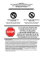
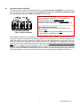
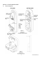
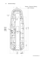
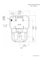
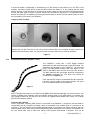
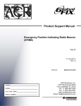
Product Support Manual
Emergency Position Indicating Radio Beacon
(EPIRB)
RLB-33
RLB-32
Y1-03-0148-2
Rev. H
FCC ID:
OWNER
VESSEL
CALL SIGN / MMSI
SERIAL NUMBER
B668L2ACR-RLB-33
B668L2ACR-RLB-32
ACR Electronics, Inc.
5757 Ravenswood Road
Fort Lauderdale, FL 33312
Tel : +1 (954) 981-3333
Fax: +1 (954) 983-5087
www.acrelectronics.com
Email: [email protected]
* * * WARNING * * *
THIS TRANSMITTER IS AUTHORIZED FOR USE
ONLY DURING SITUATIONS OF GRAVE
AND IMMINENT DANGER
DELIBERATE MISUSE MAY INCUR A SEVERE PENALTY
Magnet Safe Distance
1m (3.3 ft)
Stereo Speaker Safe Distance
1m (3.3 ft)
Keep this beacon a safe distance
away from all magnetic sources
Keep this beacon a safe distance
away from all stereo speakers
IF YOU HAVE ANY TROUBLE WITH
YOUR NEW 406 BEACON, DO NOT
RETURN IT TO THE STORE!
CALL ACR ELECTRONICS AT
+1 (800) 432-0227. WE WILL HELP YOU
RESOLVE ANY PROBLEMS YOU MY BE
EXPERIENCING. MANY QUESTIONS CAN
BE ANSWERED OVER THE PHONE.
LIMITED WARRANTY
This product is warranted against factory defect in material and workmanship for a period of five
years from date of purchase or receipt as a gift. During the warranty period ACR Electronics, Inc.
will repair or, at its option, replace at no cost to you for labor, materials or return transportation,
provided you obtain a Return Authorization from ACR Electronics, Inc., 5757 Ravenswood Road,
Ft. Lauderdale, Fl. 33312-6645. To obtain a Return Authorization, call our Customer Service
Department at (800) 432-0227. This warranty does not apply if the product has been damaged by
accident or misuse, or as a result of service or modification by other than the factory. Except as
otherwise expressly stated, the COMPANY MAKES NO REPRESENTATION OR WARRANTY OF
ANY KIND, EXPRESS OR IMPLIED, AS TO MERCHANTABILITY, FITNESS FOR A PARTICULAR
PURPOSE, OR ANY OTHER MATTER WITH RESPECT TO THIS PRODUCT. The Company shall
not be liable for, consequential or special damages.
In order to place the warranty in effect, the accompanying registration card must be returned to
us within ten days of purchase.
Table of Contents
SECTION 1 – FOREWORD AND PRODUCT FEATURES.............................................................................................. 1
SECTION 2 – REGISTRATION OF 406 MHZ BEACONS ............................................................................................... 1
2.1 Registration Importance .................................................................................................................................... 1
2.2 Where to Register............................................................................................................................................... 1
2.3 Registration in the United States...................................................................................................................... 2
2.4 Leisure Vessels in the United States................................................................................................................ 2
2.5 Commercial Vessels in the United States........................................................................................................ 2
2.6 Do I Need a Radio Station License? ................................................................................................................. 2
2.7 Commercial Vessels World Wide...................................................................................................................... 3
2.8 Registration Outside the United States............................................................................................................ 3
2.9 Change of Ownership or Contact Information ................................................................................................ 3
2.10 Lost or Stolen EPIRBs ....................................................................................................................................... 3
SECTION 3 – FALSE ALARMS ....................................................................................................................................... 3
3.1 Prevention of False Alarms ............................................................................................................................... 3
3.2 Reporting of False Alarms................................................................................................................................. 4
SECTION 4 – INSTALLATION ......................................................................................................................................... 4
4.1 Mounting Location ............................................................................................................................................. 4
4.2 Visual Inspection ................................................................................................................................................ 4
4.3 Hydrostatic Release Unit (HRU) ........................................................................................................................ 5
SECTION 5 – ACTIVATION AND DEPLOYMENT........................................................................................................... 6
5.1 Bracket Configuration........................................................................................................................................ 6
5.2 Dimension Drawings .......................................................................................................................................... 7
5.3 Configuration Overview ..................................................................................................................................... 9
5.4 GPS Acquisition with the RapidFix™ (External GPS) .................................................................................... 9
5.5 Automatic Deployment and Activation - Category 1 Beacons ...................................................................... 9
5.6 Manual Deployment and Activation.................................................................................................................. 9
5.7 Manual Activation without Deployment ......................................................................................................... 10
5.8 Deactivation ...................................................................................................................................................... 10
5.9 Full Functional Self Test .................................................................................................................................. 10
5.10 External GPS Interface: RapidFix™ Only....................................................................................................... 11
SECTION 6 – CARE AND MAINTENANCE................................................................................................................... 12
6.1 Routine Maintenance ....................................................................................................................................... 12
6.2 Battery Replacement........................................................................................................................................ 12
6.3 Shore Based Maintenance (SBM) for SOLAS Vessels, IMO MSC/Circ. 1039 ............................................. 13
6.4 Annual Testing for SOLAS Vessels, IMO MSC/Circ. 1040............................................................................ 13
SECTION 7 – THE SEARCH AND RESCUE SYSTEM ................................................................................................. 13
7.1 General Overview ............................................................................................................................................. 13
7.2 Satellite Detection ............................................................................................................................................ 13
7.3 Global Positioning System (GPS)................................................................................................................... 14
SECTION 8 – TECHNICAL INFORMATION .................................................................................................................. 14
8.1 Type Approvals and Standards ...................................................................................................................... 14
8.2 Characteristics.................................................................................................................................................. 15
8.3 Accessories ...................................................................................................................................................... 15
8.4 Specifications ................................................................................................................................................... 16
SECTION 1 – FOREWORD AND PRODUCT FEATURES
Thank you for purchasing from ACR Electronics, Inc. We design, manufacture and distribute quality products knowing
they are used to save lives. Many of our products are required to be tested and approved by regulatory bodies
worldwide. We believe in going beyond those specifications to insure our products work when needed in real world
conditions. With proper care and maintenance your ACR product will last for years. It is important that you thoroughly
read this product support manual to understand the proper care and use of your ACR product.
ACR is proud to be certified to ISO 9001: 2000, the International Standard for Quality.
This manual provides installation, operation and maintenance instructions for the RapidFix™ or Satellite2 406™
EPIRB, hereinafter referred to as the beacon except where features and functions vary. This manual also describes the
characteristics and details of the beacon system. In the USA, the FCC authorizes the use of 406 MHz Radio beacon by
any ship that is also equipped with a VHF ship station. This will make the 406 MHz radio beacon available for use on
most U.S. ships and boats. Commercial EPIRB carriage requirements are contained in IMO and/or USCG regulations.
Product
Model
Number
Product
Number
Category
Class
GPS Interface
RapidFix™
RLB-33
2776
1
1
External
RapidFix™
RLB-33
2777
2
1
External
Satellite2 406™
RLB-32
2774
1
1
None
Satellite2 406™
RLB-32
2775
2
1
None
NOTE: YOUR BEACON MAY NOT HAVE ALL OF THE FEATURES DESCRIBED IN THIS MANUAL.
SECTION 2 – REGISTRATION OF 406 MHz BEACONS
2.1
Registration Importance
It is mandatory that the owner of this 406 MHz beacon register it with the national authority.* All 406 MHz
beacons transmit a Unique Identifier Number (UIN) when activated. This UIN is programmed in the beacon
based on the country in which the beacon was purchased. Registration provides the Search and Rescue
(SAR) forces with up to date emergency contact information, which will speed up the launch of a rescue
operation. The national authorities use the information to verify if an actual emergency exists. Valuable search
and rescue resources are wasted every year responding to false alarms. SAR forces will know who you are,
what type of vessel you have, your homeport, and who to contact that might know of your current situation
ONLY if your beacon has been properly registered. This will help expedite the launch of a rescue operation. All
406 MHz beacons are required to have their registration updated every two years.
*The national authority is the governmental body responsible for EPIRB registration database administration
for the country for which the EPIRB is programmed.
2.2
Where to Register
The owner of a 406 MHz beacon (EPIRB) should register it with the national authority for which the beacon
was programmed (typically the country where purchased), regardless of where they do their boating. However,
the beacon must be reprogrammed if the boat or its owner moves or sails under a different national authority
than the one for which the beacon was previously programmed. Each beacon is programmed with a Unique
Identification Number (UIN) for the country that the unit is shipped to, and will only be accepted for registration
in that country. To verify the country, for which a beacon is programmed, see the label with the UIN on the side
of the unit. Units that do not have a country specified on the UIN label are programmed for the United States.
1
Y1-03-0227 Rev. A
2.3
Registration in the United States
It is the owner’s responsibility to register 406 MHz beacons that are programmed for and purchased in the
United States. The national authority that accepts registrations in the United States is the National Oceanic
and Atmospheric Administration (NOAA). The fastest and easiest way to register your beacon with NOAA is to
use the online registration database at www.beaconregistration.noaa.gov. If internet is not accessible then
the owner should complete the enclosed registration form (Do not confuse this with the ACR Electronics
warranty card) and mail with the pre-addressed, postage paid envelope to:
NOAA SARSAT Beacon Registration
NSOF, E/SP3
4231 Suitland Road
Suitland, MD 20746
For Faster Service, Register Online!
In the United States:
www.beaconregistration.noaa.gov
The information provided on the registration form is used only for rescue purposes. Complete and send the
registration immediately! Registration can be expedited by registering online or by faxing the registration form
to Fax # (301) 817-4565. If the beacon is going to be placed into immediate service, register online or by fax.
All registration forms will be entered in the 406 MHz beacon registration database within 48 hours of receipt. A
confirmation letter, a copy of the actual registration and a proof-of-registration decal will be mailed to you within
two weeks. When you receive these documents, please check the information carefully and affix the decal
to your beacon in the area marked “BEACON DECAL HERE.” If you do not receive confirmation back from
NOAA, call toll-free 1-888-212-7283 for assistance.
2.4
Leisure Vessels in the United States
In the United States, leisure vessels are sometimes required to have a radio station license. Leisure vessels
that are required to have a radio station license are required to modify that license when an EPIRB is added to
the vessel. For information on whether you need a radio station license, see section 2.6 (below).
2.5
Commercial Vessels in the United States
In the United States, commercial vessels that are required to have a radio station license are required to
modify that license when an EPIRB is added to the vessel. For information on whether you need a radio station
license, see section 2.6 (below).
2.6
Do I Need a Radio Station License?
The information in this section is provided for informational purposes only. Always check the FCC’s website at
http://wireless.fcc.gov/services/index.htm?job=licensing&id=ship_stations
or
call
toll-free
1-888-CALLFCC (225-5322) for the latest information.
You do not need a license to operate a marine VHF radio, radar, or EPIRBs aboard voluntary ships operating
domestically. The term "voluntary ships" refers to ships that are not required by law to carry a radio. Generally,
this term applies to recreation or pleasure craft. The term "voluntary ships" does not apply to the following:
1.
2.
3.
4.
5.
6.
7.
Cargo ships over 300 gross tons navigating in the open sea;
Ships certified by the U.S. Coast Guard to carry more than 6 passengers for hire in the open sea or
tidewaters of the U.S.;
Power driven ships over 20 meters in length on navigable waterways;
Ships of more than 100 gross tons certified by the U.S. Coast Guard to carry at least one passenger
on navigable waterways;
Tow boats of more than 7.8 meters in length on navigable waterways; and,
Uninspected commercial fishing industry vessels required to carry a VHF radio.
Ships required to carry an Automatic Identification System (AIS) transceiver by the U.S. Coast Guard
regulations enacted pursuant to the Maritime Transportation Security Act of 2000.
Ships are considered as operating domestically when they do not travel to foreign ports or do not transmit
radio communications to foreign stations. Sailing in international waters is permitted, so long as the previous
conditions are met. If you travel to a foreign port (e.g., Canada, Mexico, Bahamas, British Virgin Islands), a
license is required. Additionally, if you travel to a foreign port, you are required to have an operator permit.
2
Y1-03-0148-2 Rev. H
2.7
Commercial Vessels World Wide
406 MHz beacons that are carried on commercial vessels world wide should be registered with the country
where the vessel is flagged regardless of where the vessel operates. When a commercial vessel acquires a
406 MHz beacon from outside of its home country, the beacon should be reprogrammed for the home country
and registered there.
2.8
Registration Outside the United States
In countries other than the United States, 406 MHz beacons are registered with that country’s national
authority at the time of purchase. The sales agent should assist in filling out the forms and sending to that
country’s national authority. To verify that the unit is properly programmed for that country, view the UIN label
on the side of the unit. In the event that the beacon is not programmed for the country it has been purchased
in, the sales agent, (if properly equipped) can reprogram the unit for that country.
2.9
Change of Ownership or Contact Information
It is the owner’s responsibility to advise the national authority of any change in the information on the
registration form. If the current owner of the beacon is transferring the beacon to a new owner, the current
owner is required to inform the national authority by using their online database or by letter, fax or telephone,
of the name and address of the new owner. The new owner of the beacon is required to provide the national
authority with all of the information requested on the registration form. This obligation transfers to all
subsequent owners. Registration forms for the United States are available from NOAA by calling
1 (888) 212-7283 or by visiting our website at www.acrelectronics.com.
2.10
Lost or Stolen EPIRBs
Inform NOAA immediately at 1-888-212-SAVE (7283), or your national authority, that your EPIRB has been
lost or stolen. They will update your EPIRB registration information with the appropriate information.
Stolen EPIRBs - Things That You Need To Do:
• Report to your local authorities that the EPIRB has been stolen.
• Contact NOAA at 1-888-212-SAVE (7283), or your national authority, with the following information so
your EPIRB registration information can be updated with the appropriate remarks:
- Police Department Name - Police Phone Number - Police Case Number
If your EPIRB were to be activated, the information you provided will be forwarded to the appropriate search
and rescue authorities who will ensure that your EPIRB gets back to you. If someone attempts to register an
EPIRB reported as stolen, NOAA or your national authority will notify the appropriate police department. Visit
www.cospas-sarsat.org for more detailed information.
SECTION 3 – FALSE ALARMS
3.1
Prevention of False Alarms
An ACR 406 MHz EPIRB can be activated in an emergency by two different methods. Whether you have a
Category 1 or 2, these methods are the same.
1.
When the beacon is out of its bracket and in the water, the unit will start transmitting.
2.
When the switch is moved to the “ON” position, in or out of the bracket, the unit will start transmitting.
3.
There are a few precautions that should be taken to prevent false alarms.
•
•
•
•
Do not mount or transport beacon within 3.3 ft/1 m of a magnetic source.
Do not store beacon outside of its bracket if it can get wet.
Do not mount EPIRB backwards in its bracket (lanyard roll must not be visible).
Do not clean beacon with a water hose and brush while out of its bracket.
3
Y1-03-0148-2 Rev. H
3.2
Reporting of False Alarms
Should there be, for any reason, an inadvertent activation or false alarm, it must be reported to the nearest
search and rescue authorities. The information that should be reported includes the EPIRB 15-digit Unique
Identifier Number (UIN), date, time, duration and cause of activation, as well as location of beacon at the time
of activation.
To Report False Alarms in the United States Contact any of the Following:
Atlantic Ocean / Gulf of Mexico
USCG Atlantic Area Command Center
Tel: (757) 398-6390
Pacific Ocean Area /
USCG Area Command Center
Tel: (510) 437-3700
USCG HQ Command Center
Tel: (800) 323-7233
To Report False Alarms Worldwide contact the national authority where your beacon is registered.
SECTION 4 – INSTALLATION
4.1
Mounting Location
The location selected must be sufficiently rigid to support the weight of the total installation and at the same
time consider vibration, exposure to the elements, exposure to surrounding hazards, such as equipment
movement, doors being opened, accidental covering, personnel traffic, etc., and yet be readily accessible at all
times in the event of an emergency.
Also to be considered in selecting a location for installation is the harmful effect that certain corrosive vapors
might have on the beacon. Under no circumstances should a beacon be jeopardized by any foreign articles
being temporarily or permanently positioned during “at sea” or “in port” activities.
The beacon should face inboard on rail mount applications and should not be subjected to breaking waves.
CAUTION: Care must be taken to prevent any lanyard, line, or other emergency equipment that may be
attached to the beacon from becoming entangled or fouled which could prevent the beacon from being
removed in an emergency. Do not attach the beacon lanyard to the vessel or mounting bracket.
Do not mount the beacon in the vicinity 3.3 ft/1 m of strong magnetic or electrical fields, such as loud speakers,
radar or high power radio transmitter. The beacon should not be mounted closer than 3.3 ft/1 m. to a magnetic
navigation compass.
Mount the beacon in a vertical (antenna upward) position. In certain circumstances, such as medical
emergencies or disabled vessels, manual activation of the beacon for location and homing purposes is
sometimes requested. Mounting in this orientation provides the best homing signal.
The Category 1 float-free mounting bracket should be mounted securely to a vertical or horizontal surface (the
mount has predrilled holes for attachment to a flat surface) where there are no overhead obstructions. Location
aboard a vessel must be chosen to allow the beacon to float free of sinking craft and as high as possible,
especially on small vessels. This will help ensure operation of the hydrostatic release unit in the event the
vessel capsizes without sinking. See section 4.3 on removing the HRU.
The Category 1 float-free mounting bracket should be securely attached to the vessel. The use of #10
stainless steel hardware (not included) is recommended.
4.2
Visual Inspection
Visually inspect the area surrounding the mounting bracket installation site for hidden hazards, obstacles, etc.,
that may have been overlooked during location selection. If there is any doubt as to the ready accessibility to
the beacon at all times or if any condition may appear to be questionable, make a complete and thorough
investigation before making final approval of the installation.
4
Y1-03-0148-2 Rev. H
4.3
Hydrostatic Release Unit (HRU)
The ACR HydroFix™ HRU has an expiration date of 2 years from the date of installation or 3 years from the
date manufactured, whichever comes first. Upon installing your beacon or new HRU, permanently scratch
the new expiration date on the HRU date calendar (as seen below).
Date of Installation Example:
Date of installation of New HRU or First Installation of
EPIRB including new HRU: August 1, 2007.
This unit will need to be replaced in August of 2009.
Scratch off “AUG 8” and “2006” on the HRU date calendar
Figure 1 HRU Date Calendar
Date of Manufacture Example:
On the bottom of the HRU a date of manufacture is pin
stamped: 0806.
This unit will need to be replaced in 0809. Scratch off “AUG
8” and “2009” on the HRU date calendar
The hydrostatic release can be replaced by removing the beacon from the bracket. Firmly press down on the
spring at the bottom of the shelter, then slide the hydrostatic release assembly out of the keyed opening on the
spring and mounting bracket. Discard the old HRU. Check the date manufactured on the bottom of the new
HRU and insert the new hydrostatic release assembly in place by engaging it to the opening of the ejection
spring and case. When replacing the HRU, ACR requires that you do not reuse any parts from the previous
HRU. Failure to replace the entire assembly can cause the bracket to malfunction. Always use original ACR
replacement parts (Replacement kit P/N 9490). Use of unauthorized replacement parts will void your warranty
and may cause the bracket to malfunction. Place the beacon into the mounting bracket, (lanyard facing
inward), and replace cover, securing in place with the cotter pin going through the hydrostatic release rod.
5
Y1-03-0148-2 Rev. H
SECTION 5 – ACTIVATION AND DEPLOYMENT
5.1
Bracket Configuration
Figure 2
Figure 3
6
Y1-03-0148-2 Rev. H
5.2
Dimension Drawings
Category 1 Dimension Drawing
NOT TO SCALE
Bracket
Sensor
Magnet
(inside
bracket)
Figure 4
7
Y1-03-0148-2 Rev. H
Category 2 Dimension Drawing
NOT TO SCALE
Bracket
Sensor
Magnet
(inside
bracket)
Figure 5
8
Y1-03-0148-2 Rev. H
5.3
Configuration Overview
Category 1 beacons are designed to be automatically deployed and activated. The beacon may also be hand
held on the deck of vessels, or floated in water and attached to a raft or life vest with the lanyard provided.
Category 2 beacons are designed to be manually deployed from the bracket.
The beacon is designed to operate best while floating in water. Hand held operation should be avoided
when possible. Do not operate inside life raft or under any similar cover or canopy. Use the lanyard to attach
beacon to life raft or person after deployment. Caution - Do not attach lanyard to bracket or vessel. Both
models of the beacon can be deployed and activated manually.
Changes in the laws governing beacons have mandated that the beacon be ready at all times. If certain criteria
are met, the beacon will begin transmitting. The beacon is equipped with sensors to determine if it is in water
(a deployment condition). Category 1 and 2 brackets both contain a magnet that interacts with other sensors in
the beacon to prevent activation if it is wet (also a deployment condition).
Two conditions must be satisfied for the beacon to automatically activate:
1)
It must be out of its bracket
2)
It must be in the water
Note: Either condition by itself will not automatically activate the beacon.
The beacon is designed to allow the user to perform periodic testing while the beacon is in the release bracket.
Category 1: Place the beacon into the release bracket with the spooled lanyard inward. The beacon should
now be firmly held in the Category 1 bracket and ready for automatic deployment. Do not attach lanyard to
bracket.
Category 2: Place the beacon into the bracket with the spooled lanyard inward. The beacon should now be
firmly held in the Category 2 bracket and ready for manual deployment. Do not attach lanyard to bracket. Use
the strap and buckle to secure the beacon. The strap should be adjusted tight against the beacon; tight enough
so that it is almost difficult to engage the buckle. This should be checked periodically.
5.4
GPS Acquisition with the RapidFix™ (External GPS)
The RapidFix™ is fitted with an optical interface to connect with an external Global Positioning System
receiver that will determine the latitude and longitude of its position to be transmitted to the emergency system.
When the RapidFix™ is coupled to a working external GPS receiver, it immediately begins downloading data.
Once valid position data has been obtained, the beacon will attempt to update the positional data every 20
minutes. The RapidFix™ will always store the last valid positional data it received from the external GPS
receiver, even if it is unable to obtain updated data. It will update this data if and only if it receives new good
positional data from the external GPS receiver.
5.5
Automatic Deployment and Activation - Category 1 Beacons
Automatic deployment and activation occurs if the vessel sinks and the hydrostatic release device frees the
beacon from the bracket allowing it to float to the surface. Built-in sensors detect that the beacon is no longer
in its bracket and is in water. This condition will automatically activate the beacon.
NOTE: TRANSMISSIONS OF THE 121.5 MHZ AND 406 MHZ SIGNAL WILL NOT OCCUR UNTIL 50
SECONDS AFTER ACTIVATION.
5.6
Manual Deployment and Activation
The Category 1 beacon can be manually deployed by removing the retaining pin, removing the cover, and then
removing the beacon from the bracket. Once removed, both the Category 1 and Category 2 beacons can be
activated by placing the beacon in water OR by lifting the thumb switch to a vertical position, sliding it toward
the antenna and pushing down to the opposite side of the beacon. Activating the beacon in this manner breaks
off the Activation Indicator Plastic Pin and allows the switch to properly seat, showing the " ▌ " symbol (ON).
9
Y1-03-0148-2 Rev. H
ON position:
Notice the
Activation
Indicator
Plastic Pin
has been
broken off.
OFF position:
Note the
Activation
Indicator
Plastic Pin
Figure 6
Note: Some countries may fine vessel owners for causing false alarms. The permanent breakage of the
Activation Indicator Plastic Pin is a positive indication of a manual activation.
5.7
Manual Activation without Deployment
The beacon can be activated while still in its bracket by placing the thumb switch in the ON position. Activation
by this method overrides all sensors and turns the beacon “ON.” The caution note above still applies.
5.8
Deactivation
If manually activated, return the thumb switch to the “OFF” position.
If automatically activated: remove the beacon from the water. The beacon normally takes up to 12 seconds
to deactivate, or place the beacon back into the release bracket.
If the beacon continues to operate after it has been deactivated, remove the four screws holding the unit
together and unplug the battery to disable the unit. Return it to a service center for repair.
5.9
Full Functional Self Test
General Instructions
Please read all instructions before performing any of the tests. Be prepared to record data from the test.
Beacons may be tested in or out of the release bracket. The homing beacon at 121.5 MHz is inhibited during
self test. It is strongly recommended to perform the full functional self test on the beacon on a monthly basis or
prior to a voyage.
The self-test is initiated by momentarily lifting the thumb switch to a vertical position and holding it in this
position for at least one second (see figure 7). The initiation of the test is indicated by a beep* and the
simultaneous lighting of the green and red LEDs.
TEST
Initial Test Start
Check Data Integrity
Check 406 MHz Synthesizer
Check RF Power/Battery
Successful Test
SUCCESS
Green, Red LED
Green, Red LED
Beep,
Green, Red LED
Beep,
Green, Red LED
Beep,
Green LED, Strobe
FAIL
Test stopped
Test stopped
Test stopped
*NOTE: The “beeps” are a very high-pitched tone
that many people may not be able to hear.
Figure 7
10
Y1-03-0148-2 Rev. H
If the thumb switch is accidentally or inadvertently put in the vertical or test position (not in the OFF or ON
position), the beacon would still be turned ON and will drain the battery. It is very unlikely that this would
happen, however, if this should occur, the beacon will sound a beep once per second and will alternately flash
the red and green LEDs at a rate of one per second until the beacon is turned OFF. It is important that the
beacon be turned OFF immediately by lowering the thumb switch to the OFF position (thumb switch at rest in
the front position) if this alert is ever obtained.
Category 1 Self Test Plug
Easy Access Self Test Plug for Beacons
Remove the new Self Test Plug on the front cover for self tests. Be sure to reattach the plug to protect the
beacon from the elements. Note: You may not be able to see the LEDs but you will hear the beeps.
Figure 8
5.10
External GPS Interface: RapidFix™ Only
Your RapidFix™ comes with a GPS Optical Interface
(transmitter plug with lead wires) and a keyed GPS bezel. The
transmitter plug attaches to your RapidFix™, via the keyed
bezel. The GPS Optical Interface lead wires attach to your
GPS via the NMEA 0183 connector from your GPS receiver.
The black lead wire with gray stripes should be connected to
the positive transmitter pin. The black wire should be
connected to the negative pin.
If the external GPS receiver is operational and the connection
has been correctly made to the optical interface, the green
LED in the optical interface will start flashing.
Figure 9
NOTE: The baud rate output for your GPS receiver NMEA 0183 should be 4800 bps. If you are not sure if your
receiver is NMEA 0183 compliant, check the interface settings listed in your GPS manual. To optimize your
GPS Interface feature be sure that your GPS receiver is equipped with a NMEA 0183 Version 1.5 or higher
with GPGGA sentence enabled.
Using the GPS Interface
Once a compatible, operating GPS receiver is connected to the RapidFix™, the beacon will store data for
incorporation into the emergency message, which is transmitted to the satellite when it is activated in an
emergency. This can provide more accurate positioning data to the Search and Rescue Authority and may
lead to a faster rescue. Since the last valid GPS position data is always kept in the memory of the RapidFix™,
the user should take care to make sure that the GPS position data stored is accurate. This can be
11
Y1-03-0148-2 Rev. H
accomplished by two methods: first, by always leaving a properly functioning GPS connected to the
RapidFix™ before activation and second, by connecting a properly functioning GPS with a valid position fix
and allowing sufficient time to acquire valid GPS position data. This will take a nominal 20 minutes if old GPS
position data is stored in the memory of the RapidFix™. If there is no old GPS position data present, the
beacon will acquire current data within a minute of being connected to a GPS with a valid position fix. You can
force the RapidFix™ to update its position at any time by connecting to a GPS with a valid position fix and
initiating the Self-Test (see 5.10). If valid GPS position data is not available, the beacon will not clear the
previously stored GPS position data. In this case, call ACR Customer Service at +1 (954) 491-3933 for
instructions on how to reset the RapidFix™ with the beacon’s default message.
Testing the GPS Interface
Connect the optical interface plug to the RapidFix™ bezel and allow sufficient time for the GPS receiver to
acquire valid GPS position data (usually less than 1 minute; but it can take up to 20 minutes). Lift the thumb
switch to the vertical (Self-Test) position and release. Your RapidFix™ will confirm that it has acquired valid
GPS data by emitting a beep along with a flash of the red and green LEDs. This will occur approximately 2.5
seconds after the Self-Test.
Updating GPS Position Data
When the beacon is properly connected to a functioning and compatible GPS receiver, GPS position data is
automatically updated about every 20 minutes, while valid GPS position data is present UNLESS the beacon is
activated. The operator can force the acquisition of new GPS position data, by executing a Self-Test with the
beacon connected to a GPS with a valid position fix. This bypasses the normal, programmed, waiting time of
20 minutes for the automatic update of GPS position data. Once the RapidFix™ has completed the Self-Test
sequence by emitting the beep and flash of red and green LEDs, as described in 5.10, the RapidFix™ will
request and acquire new position data from the GPS. This can take a nominal 15 seconds or up to one minute.
NOTE: While the beacon is not activated, GPS position data will be received and continuously stored by the
RapidFix™. No GPS position data updates will occur while the beacon is activated.
A new RapidFix™ is programmed with the GPS position data set to “default.” This default GPS position data
indicates, upon activation, to the satellite system that the beacon has no valid GPS position stored in memory.
Once a functioning and compatible GPS receiver is properly connected to the beacon, this “default” data will
be replaced by valid GPS position data, as described in the previous sections.
SECTION 6 – CARE AND MAINTENANCE
6.1
Routine Maintenance
At least every ninety days, the float free mounting bracket and beacon should be inspected for deterioration
and/or residue buildup that may affect the function of the beacon or automatic release. Part of the visual check
includes checking the antenna for tightness. Clean the beacon and the mounting bracket to remove residue
buildups. It is recommended that the beacon and mounting bracket be wiped with a damp cloth.
Carefully inspect the beacon case for any visible cracks. Cracks may admit moisture, which could falsely
activate the beacon or otherwise cause a malfunction. Any cracking observed should be immediately referred
to ACR for evaluation by calling 1-800-432-0227 ext. 2155 in the US, or +1-954-981-3333 ext 2155 elsewhere.
6.2
Battery Replacement
The battery must be replaced by the date indicated on the beacon or every five (5) years, whichever occurs
first. At each inspection, check the time remaining until replacement is required. The battery should be
replaced if the beacon has been activated for any use other than the self test.
Always refer all long life battery replacement and other beacon service to a factory authorized service center.
Battery replacement includes servicing the beacon by replacing all o-rings, testing the water seal and the
electrical properties.
NOTE: There are no user serviceable items inside the beacon. DO NOT OPEN THE BEACON UNLESS TO
DISABLE IN CASE OF FAULTY ACTIVATION.
For the nearest location of a Battery Replacement Center, visit our website at www.acrelectronics.com
The beacon may or may not require special shipping instructions due to the lithium batteries and changes in
shipping regulations. Please refer to ACR’s website www.acrelectronics.com for proper shipping instructions.
12
Y1-03-0148-2 Rev. H
6.3
Shore Based Maintenance (SBM) for SOLAS Vessels, IMO MSC/Circ. 1039
The Maritime Safety Committee approved guidelines for shore-based maintenance of satellite beacons, for the
purpose of establishing standardized procedures and minimum levels of service for the testing and
maintenance of satellite beacons. First Shore Based Maintenance on all ACR EPIRBs is due at the date of the
first battery replacement.
6.4
Annual Testing for SOLAS Vessels, IMO MSC/Circ. 1040
SOLAS regulation IV/15.9 dictates annual testing of 406 MHz satellite EPIRBs. Testing should be carried out
using suitable test equipment capable of performing the relevant measurements. All checks of electrical
parameters should be performed in the self-test mode, if possible.
SECTION 7 – THE SEARCH AND RESCUE SYSTEM
7.1
General Overview
Beacons provide distress alerts via radio transmission on 406 MHz to the LEOSAR satellites of the COSPASSARSAT network. The RapidFix™ can also transmit a distress alert (acquired by the internal or external GPS)
to the GEOSAR network that includes GPS latitude and longitude coordinates.
The message transmitted is unique for each beacon, which provides identification of the transmitter through
computer access of registration files maintained by the National Oceanic and Atmospheric Administration or
other national authority*. Remember, SAR forces will know who you are, what type of vessel you have, your
homeport, and who to contact that might know of your current situation ONLY if your beacon has been properly
registered. This will help expedite the launch of a rescue operation. 406 MHz beacons are required to have
their registration updated every two years.
*The national authority is the governmental body responsible for EPIRB registration database administration
for the country for which the EPIRB is programmed.
Once the 406 MHz signal is relayed through the LEOSAR and/or GEOSAR network, SAR forces determine
who is closest, and then proceed to the beacon using the 121.5 MHz homing frequency.
7.2
Satellite Detection
EPIRBs transmit to the satellite portion of the COSPAS-SARSAT system. COSPAS-SARSAT is an
international system that utilizes Russian Federation and United States’ low altitude, near-polar orbiting
satellites (LEOSAR). These satellites assist in detecting and locating activated 406 MHz satellite beacons.
COSPAS and SARSAT satellites receive distress signals from EPIRBs transmitting on the frequency of 406
MHz. The COSPAS-SARSAT 406 MHz beacon signal consists of a transmission of non-modulated carriers
followed by a digital message format that provides identification data. The 406 MHz system uses Satelliteborne equipment to measure and store the Doppler-shifted frequency along with the beacon’s digital data
message and time of measurement. This information is transmitted in real time to an earth station called the
Local User Terminal (LUT), which may be within the view of the satellite, as well as being stored for later
transmission to other LUTs.
The LUT processes the Doppler-shifted signal from the LEOSAR and determines the location of the beacon,
then the LUT relays the position of the distress to a Mission Control Center (MCC) where the distress alert and
location information is immediately forwarded to an appropriate Rescue Coordination Center (RCC). The RCC
dispatches Search and Rescue (SAR) forces.
The addition of the GEOSAR satellite system greatly improves the reaction time for a SAR event. This satellite
system has no Doppler capabilities at 406 MHz, but will relay the distress alert to any of the LUT stations.
When there is GPS data included in the distress message, SAR authorities instantly know your location to
within 110 yards (100 m). This speeds up the reaction time by not having to wait for one of the LEOSAR
satellite to pass overhead. Because most of the search and rescue forces presently are not equipped to home
in on the 406 MHz Satellite beacons signal, homing must be accomplished at 121.5 MHz.
13
Y1-03-0148-2 Rev. H
Figure 10- Satellite Coverage
7.3
Figure 11- GEOSAR Satellite Orbits
Global Positioning System (GPS)
The GPS system is a satellite group that enables a GPS
receiver to determine its exact position to within 30 m
(100 ft.) anywhere on earth. With a minimum of 24 GPS
satellites orbiting the earth at an altitude of approximately
11,000 miles they provide users with accurate information
on position, velocity, and time anywhere in the world and
in all weather conditions. The RapidFix™ stores this data
into its distress transmission allowing search and rescue
forces to narrow the search into a very small area and
thus minimize the resources required and dramatically
increase the effectiveness of the overall operation.
Figure 12 - GPS Satellite Orbits
SECTION 8 – TECHNICAL INFORMATION
8.1
Type Approvals and Standards
The RLB-32 and RLB-33 meet the requirements of Federal Communication Commission (FCC) Part 80 and
Category 1 EPIRBs meet the GMDSS requirements:
Type Approvals
FCC
COSPAS-SARSAT
MED
FCC ID: B668L2ACR-RLB-33 (RLB-33)
FCC ID: B668L2ACR-RLB-32 (RLB-32)
Certificate No. 108 (RLB-33)
Certificate No. 107 (RLB-32)
BSH Certificate No.: 6492/050564-2/2004 (RLB-33)
BSH Certificate No.: 6492/050564-1/2004 (RLB-32)
Notified Body: 0735
Copies of certificates and additional worldwide type approvals are available at www.acrelectronics.com.
14
Y1-03-0148-2 Rev. H
Applicable Standards
Part 80 Subpart V – EPIRBs
FCC
Part 80 Subpart W – GMDSS (Cat. 1 only)
RTCM
RTCM Recommended Standards for 406 MHz Satellite EPIRBs
C/S T.001 – Specification for C/S 406 MHz Distress Beacons
COSPAS/SARSAT
C/S T.007 –C/S 406 MHz Distress Beacon Type Approval Standard
Annex A.1, Item No. A.1/5.6 – 406 MHz (C/S) Satellite EPIRB
MED
Annex B, Model B
IMO Resolution A.694(17) – General Requirements for GMDSS Equipment
IMO
IMO Resolution A.810(19) – Performance Standards for Float-Free Satellite
406 MHz EPIRBs (Cat. 1 only)
8.2
8.3
Characteristics
The EPIRB is a buoyant, battery operated unit. The beacon case, with its external antenna, is waterproof. The
semiconductor circuits are mounted within the case assembly that also contains the battery power supply. A
“Test/ON” switch is installed on top of the beacon, along with a strobe light. The Category 1 beacon must be
stored in its special mount, free of obstructions aboard a vessel for automatic float-off. The unit is self-buoyant
and no external flotation devices are required.
Accessories
Product
Category 1
Mounting Case
6.5" x 17.1" (16.51 cm x 43.4 cm)
Category 2
Mounting Brackets
6.0" x 7.7" (15.2 cm x 19.5 cm)
Category 1
GPS Interface Plug- Rapid Fix
Category 2
GPS Interface Plug- Rapid Fix
Universal HRU Kit
Replacement Antenna
Product Number
9455
9430
9388.1
9388
9490
9368
15
Y1-03-0148-2 Rev. H
8.4
Specifications
406 MHz Transmitter
406 MHz
Frequency
Output
5 Watts
Power
Digital
RLB-33: Standard Location Protocol2
Message
RLB-32: Standard Location Protocol1
Format
RLB-33: 520 ms
Duration
RLB-32: 440 ms
Frequency
±2 parts per billion/100ms
Stability
400 bps
Rate
±1.1 radians peak
Modulation
Biphase L
Encoding
1
Leaves ACR with Serialized U.S. code but can be
reprogrammed at a service center to Maritime or
other coded format including nationality of
registration.
2
Leaves ACR with Serialized U.S. code but can be
reprogrammed at a service center to Maritime MMSI.
Battery Life
Operating
48 hours minimum
Replacement
Interval
Operating
Temp Range
Storage
Temp Range
Xenon Strobe
Light Color
Output
Power
Flash Rate
5 years or after use in an emergency
CLASS 1
CLASS 2
CLASS 1
CLASS 2
-40°C to +55°C
-20°C to +55°C
-50°C to +70°C
-40°C to +70°C
121.5 MHz Transmitter
121.5 MHz
Frequency
Frequency
±50 ppm
Tolerance
Output
Power
50-100 mW PEP
Modulation
AM (3K20A3X)
Type
Sweep
400 to 1200 Hz
Range
Sweep Rate 3 Hz
37.5%
Duty Cycle
General/Environmental
Size
7.2 x 4.3 x 3.7 in.
(without
(18.4 x 10.9 x 9.3 cm)
antenna)
Antenna
7.39" (18.77 cm)
Height
EPIRB
High impact UV resistant plastic
Material
High Vis Yellow
Color
1.9 lbs. (861g)
Weight
Exceeds RTCM Standards Factory Tested to 33 ft/10 m at
Waterproof
room temperature
Antenna
Frequency
406 & 121.5 MHz
Polarization
Vertical
VSWR
Less than 1.5/1
White
0.75 effective candela
20-30 per minute
16
Y1-03-0148-2 Rev. H
ACR Electronics, Inc.
5757 Ravenswood Road, Ft. Lauderdale, FL 33312-6645
Tel: +1 (954) 981 3333 Fax: +1 (954) 983-5087
www.acrelectronics.com
European Office
1 Rose Cottages, Pitmore Lane, Sway,
Lymington, Hampshire SO41 6BX UK
Tel: +44-1590-682282 Fax: +44-1590-683828
Email: [email protected]
MARINE EQUIPMENT DIRECTIVE
DECLARATION OF CONFORMITY
We hereby declare that the following product is in conformity with the Council Directive 96/98/EC of 20 December 1996
on Marine Equipment as amended by Commission Directive 2002/75/EC of 2 September 2002 and that it has been
type examined as follows.
Product:
406 MHz (COSPAS-SARSAT) Emergency Position Indicating Radio Beacon
(EPIRB) ACR RapidFix™ 406 RLB-33 (Cat. 1 & Cat. 2)
Notified Body:
Bundesamt fϋr Seeschifffahrt und Hydrographie (BSH) – Germany
Notified Body No. 0735
Certificate No.6492/050564-2/2004
Type Examination:
Standards
Annex A.1, Item No. A.1/5.6 and Annex B, Module B in the Directive
IMO Res. A.810(19)
IMO MSC.56(66), MSC.120(74)
IMO MSC/Circ.862
IMO Res. A.694(17)
IEC 61097-2
IEC 60945
ETS 300 066
COSPAS-SARSAT C/S T.001
COSPAS-SARSAT C/S T.007
Manufacturer:
ACR Electronics Inc. Fort Lauderdale, Florida, USA
EU Representative:
ACR Electronics Inc. (European Office)
Lymington, Hampshire UK.
Signed on behalf of ACR Electronics Inc.
Signed : _________________________________
Name: John F. Flood
Date : April 11, 2006
Title: V.P. Engineering
17
Y1-03-0148-2 Rev. H
ACR Electronics, Inc.
5757 Ravenswood Road, Ft. Lauderdale, FL 33312-6645
Tel: +1 (954) 981 3333 Fax: +1 (954) 983-5087
www.acrelectronics.com
European Office
1 Rose Cottages, Pitmore Lane, Sway,
Lymington, Hampshire SO41 6BX UK
Tel: +44-1590-682282 Fax: +44-1590-683828
Email: [email protected]
MARINE EQUIPMENT DIRECTIVE
DECLARATION OF CONFORMITY
We hereby declare that the following product is in conformity with the Council Directive 96/98/EC of 20 December 1996
on Marine Equipment as amended by Commission Directive 2002/75/EC of 2 September 2002 and that it has been
type examined as follows.
Product:
406 MHz (COSPAS-SARSAT) Emergency Position Indicating Radio Beacon (EPIRB)
ACR Satellite2 406™ RLB-32 (Cat. 1 & Cat. 2)
Notified Body:
Bundesamt fϋr Seeschifffahrt und Hydrographie (BSH) – Germany Notified Body No. 0735
Certificate No.6492/050564-1/2004
Type Examination:
Standards
Annex A.1, Item No. A.1/5.6 and Annex B, Module B in the Directive
IMO Res. A.810(19)
IMO MSC.56(66), MSC.120(74)
IMO MSC/Circ.862
IMO Res. A.694(17)
IEC 61097-2
IEC 60945
ETS 300 066
COSPAS-SARSAT C/S T.001
COSPAS-SARSAT C/S T.007
Manufacturer:
ACR Electronics Inc. Fort Lauderdale, Florida, USA
EU Representative:
ACR Electronics Inc. (European Office)
Lymington, Hampshire, UK.
Signed on behalf of ACR Electronics Inc.
Signed : _________________________________
Name: John F. Flood
Date: April 11, 2006
Title: V.P. Engineering
18
Y1-03-0148-2 Rev. H
ACR Electronics, Inc.
5757 Ravenswood Road, Ft. Lauderdale, FL 33312-6645
Tel: +1 (954) 981 3333 Fax: +1 (954) 983-5087
www.acrelectronics.com
European Office
1 Rose Cottages, Pitmore Lane, Sway,
Lymington, Hampshire SO41 6BX UK
Tel: +44-1590-682282 Fax: +44-1590-683828
Email: [email protected]
INTERNATIONAL MARITIME ORGANIZATION
SHORE BASED MAINTENANCE
The Maritime Safety Committee approved guidelines for shore-based maintenance (SBM) of satellite EPIRBs, for the
purpose of establishing standardized procedures and minimum levels of service for the testing and maintenance of
satellite EPIRBs to ensure maximum reliability whilst minimizing the risk of false distress alerts.
Ref. T2/6.01
MSC/Circ.1039
Products:
406 MHz (COSPAS-SARSAT) Emergency Position-Indicating Radio Beacons (EPIRBs):
• ACR Satellite 406™ RLB-27/28 (Cat. 1 & Cat. 2)
• ACR Satellite2 406™ RLB-32 (Cat. 1 & Cat. 2)
• ACR RapidFix™ RLB-33 (Cat. 1 & Cat. 2)
• ACR GlobalFix™ RLB-35 (Cat. 1 & Cat. 2)
• ACR Float Free 406 Memory Capsule RLB-35MC (Cat. 1)
Maintenance
Service Interval:
406 MHz satellite EPIRBs should be inspected and tested annually in accordance with
MSC/Circ.1040. Shore-based maintenance of all satellite EPIRBs should be carried out
by the flag administration and not exceeding 5 years. It is recommended that
maintenance be performed at the time when the battery is to be changed.
All ACR 406 MHz EPIRBs shall have their first shore-based maintenance performed on
the same dates as their battery replacement.
SBM Providers:
ACR only authorizes battery replacements and shore based maintenance to be
performed by certified ACR service providers.
Manufacturer:
ACR Electronics Inc., Fort Lauderdale, Florida USA
Signed on behalf of ACR Electronics Inc.
Signed : _________________________________
Name: John F. Flood
Title: V.P. Engineering
Date: September 27, 2006
19
Y1-03-0148-2 Rev. H
ACR ELECTRONICS INC.
PRODUCT INFORMATION FOR PEOPLE’S REPUBLIC OF CHINA
NOTE TO USERS OF GlobalFix™, RapidFix™, or Satellite2 406™,
NAT GPIRB, SATFIND 406, GEOTRACK 406
Table 1
Toxic or Hazardous Substances or Elements
Component Name
Printed circuit
assembly
Battery pack assembly
Lead
(Pb)
Hexavalent
Chromium
(Cr6+)
Polybrominated
Biphenyls (PBB)
Polybrominated
Diphenyl Ethers
(PBDE)
Mercury
(Hg)
Cadmium
(Cd)
X
O
O
O
O
O
X
O
O
O
O
O
O: Indicates that the toxic or hazardous substance contained in all of the homogeneous materials for this component is below the limit
requirement in SJ/T11363–2006
X: Indicates that the toxic or hazardous substance contained in at least one of the homogeneous materials used for this component is
above the limit requirement in SJ/T11363–2006
Assemblies include population of components, solder and interconnects.
Product Marking Explanations
In accordance with the requirements specified in SJ/T11364–2006, all ACR EIPs sold in the People’s Republic of
China are marked with a pollution control marking. The following marking applies to ACR products.
This marking indicates that some homogeneous substance within the EIP contains toxic or hazardous substances or
elements above the requirements listed in SJ/T11363–2006. These substances are identified in Table 1.
Environmentally Friendly Use Period
The number in the marking, shown as 20 in the illustration above, refers to the EIP’s Environmentally Friendly Use
Period (EFUP). The EFUP is the number of years from the date of manufacture that toxic or hazardous substances or
elements contained in EIPs will not leak or mutate under the normal operating conditions described in the EIP user
documentation, resulting in any environmental pollution, bodily injury, or damage to assets.
Note Except as expressly stated herein and as required under mandatory provisions of regulations of the People’s
Republic of China, ACR Electronics Inc. makes no representation or warranty of any kind, expressed or implied, with
respect to the EFUP and expressly disclaims any representations or warranties, expressed or implied, with respect to
the EFUP.
20
Y1-03-0148-2 Rev. H
ACR ELECTRONICS INC.
中华人民共和国产品信息
GlobalFix™ RLB-35, RapidFix™ RLB-33, or Satellite2 406™ RLB-32,
NAT GPIRB, SATFIND 406, GEOTRACK 406 用户须知
表1
有毒有害物质或元素
部件名称
汞 (Hg)
镉 (Cd)
六价铬 (Cr6+)
多溴联苯 (PBB)
多溴二苯醚 (PBDE)
印刷电路板组件
X
O
O
O
O
O
电池组件
X
O
O
O
O
O
铅 (Pb)
O: 表示该有毒有害物质在该部件所有均质材料中的含量均在SJ/T11363-2006 标准规定的限量要求以下。
X: 表示该有毒有害物质至少在该部件的某一均质材料中的含量超出SJ/T11363-2006 标准规定的限量要求。
组件包含元器件,焊接材料和连接件
产品标识说明
根据SJ/T11364-2006 的要求,中华人民共和国境内销售的所有ACR 电子信息产品均注明污染控制标识。 ACR
产品使用以下标识。
该标识表示该电子信息产品某一均质材料中有毒、有害物质或元素的含量超出SJ/T11363-2006 规定的限量。
相关物质见表1。
可能由于产品体积或功能等因素而未直接在产品上注明。 但产品仍符合SJ/T11364-2006 的要求,且其标识信息已在本文说明。
环保使用期限
标识中的数字(即上述图例中的“20”)指电子信息产品环保使用期限 (EFUP) 。 电子信息产
品环保使用期限是指在正常使用的条件下,电子信息产品中含有的有毒、有害物质或元素不会
发生外泄或突变并导致对环境造成严重污染或对人身、财产造成严重损害的期限。
注除根据中华人民共和国法规的强制性规定在此作出明示声明的以外, ACR Electronics Inc.
对电子信息产品环保使用期限不作任何形式的陈述或保证(无论是明示或默示),并且不对电子信息产品环保使用期限
的任何陈述或保证(无论是明示或默示)承担任何责任。
21
Y1-03-0148-2 Rev. H