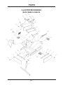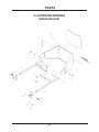
1
OWNER/OPERATOR’S
MANUAL & PARTS LIST
STUMP GRINDER
Model KC180
Revised 06/15/12
09.10017
328 East Water St.
PO Box 148
Orrville, Oh 44556
www.ventrac.com
To the Owner
Contact Information and Product Identification
If you need to contact an authorized Ventrac dealer for information on servicing your product,
always provide the product model and serial numbers.
Please fill in the following information for future reference. See picture below to find the
location of the identification number. Record them in the spaces provided below.
Date of Purchase: ______________________________________________________________
Dealer: _______________________________________________________________________
Dealer Address: ________________________________________________________________
________________________________________________________________
Dealer Phone Number: __________________________________________________________
Dealer FAX Number: ____________________________________________________________
Model # (A): _______________________
Serial # (B): ________________________
Affix Part/Serial Number label here
Venture Products Inc. reserves the right to make changes
in design or specifications without obligation to make like
changes on previously manufactured products.
ii
TABLE OF CONTENTS
INTRODUCTION
SECTION A
Description & Specifications . . . . . . . . . . . . . . . . . . . . . . . . . . . . A-1
SAFETY
SECTION B
Safety Symbols . . . . . . . .
Decals . . . . . . . . . . . . .
General Safety Procedures . .
Safety Operation & Techniques
.
.
.
.
.
.
.
.
.
.
.
.
.
.
.
.
.
.
.
.
.
.
.
.
.
.
.
.
.
.
.
.
.
.
.
.
.
.
.
.
.
.
.
.
.
.
.
.
.
.
.
.
.
.
.
.
.
.
.
.
.
.
.
.
.
.
.
.
.
.
.
.
.
.
.
.
.
.
.
.
.
.
.
.
.
.
.
.
SETUP & OPERATION
Mirror Installation
Attaching. . . . .
Detaching . . . .
Operating . . . .
.
.
.
.
.
.
.
.
.
.
.
.
.
.
.
.
.
.
.
.
.
.
.
.
.
.
.
.
B-1
B-2
B-3
B-4
SECTION C
.
.
.
.
.
.
.
.
.
.
.
.
.
.
.
.
.
.
.
.
.
.
.
.
.
.
.
.
.
.
.
.
.
.
.
.
.
.
.
.
MAINTENANCE & SERVICE
.
.
.
.
.
.
.
.
.
.
.
.
.
.
.
.
.
.
.
.
.
.
.
.
.
.
.
.
.
.
.
.
.
.
.
.
.
.
.
.
.
.
.
.
.
.
.
.
.
.
.
.
.
.
.
.
.
.
.
.
.
.
.
.
.
.
.
.
.
.
.
.
. . C-1
. . C-2
. . C-2
C-2 & 3
SECTION D
Maintenance . . . . . . . . . . . . . . . . . . . . . . . . . . . . . . . . . . . . D-1
PARTS & ILLUSTRATED DRAWINGS
SECTION E
Main Frame & Shields . . . . . . . . . . . . . . . . . . . . . . . . . . . . . E-1 & 2
Drive & Pulleys . . . . . . . . . . . . . . . . . . . . . . . . . . . . . . . . E-3 & 4
Mirror Bracket . . . . . . . . . . . . . . . . . . . . . . . . . . . . . . . . . E-5 & 6
WARRANTY
iii
INTRODUCTION
Product Description
KC180
The KC180 stump grinder is an easy-to-mount VENTRAC attachment that allows quick
removal of unwanted stumps and roots. Heavy duty carbide cutters provide extended
and effective performance in spite of dirt, stones, and debris in the work area.
When not in use, an adjustable hitch mounted stand holds the stump grinder in an
upright position for easy re-attachment.
A convex mirror is mounted on front of the tractor and above the grinder attachment to
provide excellent operator visibility to the front cutting edge.
Turning the steering wheel creates a side-to-side cutting action. Forward and reverse
movement is controlled with the tractors hydrostatic drive.
Ventrac KC180 Specifications
Overall Height . . . . . . . . . . . . . . . . . . . . . . . . . . . 19 inches
Overall Width. . . . . . . . . . . . . . . . . . . . . . . . . . . . 27 inches
Overall Length
. . . . . . . . . . . . . . . . . . . . . . . . . . 33 inches
Cutter Head Width . . . . . . . . . . . . . . . . . . . . . . . . 3.5 inches
Overall Cutter Head Diameter. . . . . . . . . . . . . . . . . . . 18 inches
Cutter Head Speed . . . . . . . . . . . . . . . . . . . . . . . . . 900 RPM
Cutting Depth Below Ground Level . . . . . . . . . . . . . . . . 6 inches
Weight . . . . . . . . . . . . . . . . . . . . . . . . . . . . . . 170 pounds
A-1
SAFETY
ATTENTION:
This symbol identifies potential
health and safety hazards. It marks
safety precautions. Your safety and
the safety of others is involved.
SIGNAL WORD DEFINITIONS
Indicates an imminently hazardous
situation which, if not avoided, will result in
death or serious injury. This signal word is
limited to the most extreme cases.
Indicates a potentially hazardous situation
which, if not avoided, could result in death
or serious injury.
Indicates a potentially hazardous situation
which, if not avoided, may result in minor
or moderate injury and/or property
damage. It may also be used to alert
against unsafe practices.
B-1
SAFETY
Decals
The following safety decals must be maintained on your Ventrac Attachment. If
any decals are faded or missing, contact your dealer promptly for replacements.
C
A
B
D
Decal
Page &
Location
Description
Part Number
A
E-1, #16
Warning - Moving Part Hazard
00.0101
B
E-1, #18
Danger - Pinching Hazard
00.0102
C
E-1, #17
Danger - Keep Hands and Feet Away
00.0123
D
E-1, #23
Warning - Read Owner's Manual
00.0217
B-2
SAFETY
General Safety Procedures
for Ventrac Tractors, Attachments, & Accessories
Read and understand the operator’s manual before operating this equipment.
Observe and follow all safety decals.
DO NOT let children or any untrained person operate the tractor or attachment.
Make sure that all operators of this equipment are thoroughly trained in using it
safely.
Never allow additional riders on the tractor or attachments.
DO NOT operate tractor or attachments if you are under the influence of alcohol,
drugs, medication that may impair judgment or cause drowsiness, or if you are not
feeling well.
Operate all controls from the operators seat only.
Before operating equipment, make sure all shields are in place and fastened.
Ensure the attachment or accessory is locked or fastened securely to the tractor
(power unit) before operating. See tractor manual for locking procedure.
Ensure that all bystanders are clear of the tractor and attachment before operating.
Be especially careful and observant if other people are present. Never assume that
bystanders will remain where you last saw them.
Always look in the direction the tractor is moving.
Never direct the discharge of any attachment in the direction of people, animals,
buildings, vehicles, or objects of value.
Immediately stop at any sign of equipment failure and correct the problem before
continuing to operate. An unusual noise can be a warning of equipment failure.
Before adjusting, cleaning, lubricating, or changing parts on the tractor or attachment,
engage the parking brake, lower the attachment to the ground, stop the engine, and
remove the ignition key.
To prevent the risk of uncontrolled equipment movement on tractors equipped with 2
speed axles, always shift the transaxle range with the power unit stationary on level
ground and with the parking brake engaged.
If equipment is to be left unattended, engage the parking brake, lower the attachment
to the ground, stop the engine, and remove the ignition key.
B-3
SAFETY
KC180 Safety Procedures
Before making any repairs or adjustments, lower
attachment to the ground, set parking brake, shut
the engine off, and remove the key.
Read and understand the operator’s manual before
operating this equipment.
Always wear hearing and eye protection when
operating the Stump Grinder.
During the grinding process, objects can be
propelled from cutter causing possible injury to
bystanders. Setup plywood or equivalent shielding
in high traffic or pedestrian areas.
B-4
SETUP & OPERATION
MIRROR INSTALLATION INSTRUCTIONS
1. Install the right and left mount brackets (Page E-5, Ref. 2 & 3) to the front sides of
the tractor chassis at the front bumper mount.
The KT4100 & KT4200 use only the top and bottom mounting holes.
The HT4000 uses all three mounting holes. The top two holes on each bracket
require a flat washer between the bracket and the tractor to level the mounting
surface.
NOTE: an HT4000 with a Kawasaki engine will require modification of the hole spacing.
2. Assemble the two attachment arms (E-5, Ref. 4) as shown on page E-5. The two
bolts in the cross-over bracket should only be finger-tight until the correct setting has
been verified at the end of the assembly procedure.
3. Install the attachment arms an equal distance into the mount brackets on the tractor.
Secure them with the side adjustment screws.
NOTE: install with the cross-over bracket in the high position to give adequate
clearance for the grinder in the raised position.
4. Mount the mirror housing (E-5, Ref. 16) to the outer ends of the attachment arms.
For a trial setting, we recommend selecting a hole near the center of the adjustment
options. Use the identical hole on the opposite side. Install the bolts, washers, and
nuts as shown on page E-5.
5. Install the pivot bolts as shown on page E-5.
6. Install the mirror into the right and left slots inside the mirror housing. Install the four
rubber stops (E-5, Ref. 14) around the perimeter of the mirror to secure it.
8. Test the results by sitting on the tractor seat to determine if the settings allow the
operator to SEE the action of the grinder. Make any necessary adjustments and
tighten all nuts and bolts.
Remove the mirror when not using the stump grinder. Loosen the side adjustment
screws and slide the attachment arms out of the mount brackets. Clean the mirror of
any dust and debris and store in a safe place.
C-1
OPERATION
Operation
Attaching:
1. Drive the tractor slowly forward into the hitch arms on the stump grinder. Align the
hitch arms to complete the engagement.
2. Once completely engaged, close the front hitch latch.
3. Stop the tractor engine.
4. Place attachment belt on the PTO drive pulley of the tractor.
5. Engage the PTO spring tension lever.
6. Raise the stand to give maximum ground clearance.
7. Mount mirror attachment brackets to front frame of tractor at the same location as
the front bumper. Slide mirror attachment arms into the attachment brackets and
tighten the T-handle bolts.
Detaching:
1. Park the tractor on a level surface and set the parking brake.
2. Shut off tractor engine.
3. Release PTO spring tension slowly.
4. Dismount and remove the attachment belt from tractor drive pulley. Adjust the stand
to support the stump grinder.
5. Disengage the front hitch latch.
6. Restart the tractor and slowly back away from the stump grinder.
Operating Techniques and Tips:
The transaxle on the tractor should be in low range when grinding.
The operator must be sitting on the tractor seat (4100 & 4200) or seat belt must be
fastened (4000) before the PTO can be engaged. Adequate engine rpms
(approximately 2000-3000) may be necessary before engaging the PTO as the cutting
wheel is very heavy. Near full rpms are recommended for most grinding. If a good grind
can be maintained and there is sufficient power, reducing the rpms by 200 or 300 may
result in better fuel economy and reduction in the wear-and tear of the equipment.
C-2
OPERATION
Operating Techniques and Tips (cont.)
Grinding:
Before grinding, cut stump as low to the ground as possible with a chain saw. Position
the grinder above the closest edge of the stump and lower slowly until it begins to cut.
Turn the steering wheel left and right to sweep the cutter head across the stump. After
each pass, lower the grinder a little more and repeat the process.
After removing several inches on larger stumps, it is necessary to move forward and
repeat the process. Also on large stumps, it is advisable to approach from several
different angles.
Follow this procedure until the stump is cut to desired depth below the ground surface.
If the grinder is lowered to much at one time it will not allow the tractor to be steered. Lift
the grinder slightly to continue side-to-side grinding.
There are variables in stumps. Hardwoods cut much slower than softwoods. Partially
decayed stumps may cut easy in some spots, but still have some hard spots or tough
roots. Experience will help the process be more efficient.
Do not grind in a position that allows the cutter to be in continuous contact with a rock.
The carbide teeth provide some of the best wear under any condition, but they are more
efficient if they are sharp.
During the grinding process, objects can be
propelled from cutter causing possible injury to
bystanders. Set up plywood or equivalent shielding
in high traffic or pedestrian areas.
C-3
MAINTENANCE & SERVICE
Maintenance
Grease the bearings every 50 hours. Do not over grease. Usually one pump is
sufficient.
Check gearbox oil every 100 hours or seasonally, whichever comes first. If necessary,
add 80-90 weight gear oil. Oil level should be halfway up in gearbox.
The cutter teeth (KC180 serial # 1231-) have three shoulders. If a tooth becomes dull or
damaged, loosen the top nut, tap the tooth down, rotate the tooth a third of a turn, and
re-tighten the top nut. Cutter teeth can be sharpened with the proper equipment.
Sharpening carbide teeth requires a special process. See your authorized Ventrac
dealer for replacement parts or instructions on sharpening existing teeth. Teeth that
have lost more than 1/8” of original bite must be replaced.
Occasionally the (3) cutter head drive belts may need to be tightened. The following
procedure MUST be used in order to keep the cutter head and shaft in line with the
frame.
Shut off the tractor, apply the park brake, and remove the key.
Loosen the (4) nuts (A) on the bearings on either side of the cutter head. Loosen the
locking nut (C) on the back of the right adjustment plate. Loosen the locking nut (D) on
the front of the left adjustment plate.
Tighten the belts by tightening the nut (B) on the front of the right adjustment plate while
loosening the nut (E) on the back of the left adjustment plate accordingly. ALWAYS
adjust nuts (B & E) equally, so that the rotor shaft remains parallel to the gearbox shaft.
After the belts are tight, tighten locking nuts (C & D), then tighten the (4) bearing nuts
(A).
D
B
A
D-1
PARTS
MANUAL
KC180
PARTS
ILLUSTRATED DRAWING
MAIN FRAME & SHIELDS
E-1
PARTS
MAIN FRAME & SHIELDS
REF.
1
2
3
4
5
6
PART NO.
.
.
.
.
.
.
DESCRIPTION
QTY.
.
.
.
.
.
.
.
.
.
.
.
.
.
.
.
.
.
.
.
.
.
.
.
.
.
.
.
.
.
.
.
.
.
.
.
.
44.0195.
64.0958.
62.0911.
60.0818.
64.0957.
03.0009.
.
.
.
.
.
.
.
.
.
.
.
.
.
.
.
.
.
.
.
.
.
.
.
.
.
.
.
.
.
.
.
.
.
.
.
.
.
.
.
.
.
.
.
.
.
.
.
.
Belting Curtain . . . . . . .
Belting Clamp Bar . . . . .
Main Frame . . . . . . . .
Pulley Shield . . . . . . . .
Stand. . . . . . . . . . . .
1/4 x 1-3/8 Safety Snap Pin
.
.
.
.
.
.
.
.
.
.
.
.
.
.
.
.
.
.
.
.
.
.
.
.
.
.
.
.
.
.
.
.
.
.
.
.
.
.
.
.
.
.
.
.
.
.
.
.
.
.
.
.
.
.
3
2
1
1
1
1
7 .
8 .
9 .
10
11
12
.
.
.
.
.
.
.
.
.
.
.
.
.
.
.
.
.
.
.
.
.
.
.
.
.
.
.
.
.
.
99.SF0405-1
99.A04 . . .
99.SF0404 .
99.SF04 . .
99.SF05 . .
60.0816. . .
.
.
.
.
.
.
.
.
.
.
.
.
.
.
.
.
.
.
.
.
.
.
.
.
.
.
.
.
.
.
.
.
.
.
.
.
.
.
.
.
.
.
1/4-20 x 5/8 Flange Bolt w/Rubber.
1/4-20 Lock Nut . . . . . . . . . .
1/4-20 x 1/2 Flange Bolt . . . . . .
1/4-20 Flange Nut . . . . . . . . .
5/16-18 Flange Nut . . . . . . . .
Drive Cover . . . . . . . . . . . .
.
.
.
.
.
.
.
.
.
.
.
.
.
.
.
.
.
.
.
.
.
.
.
.
.
.
.
.
.
.
.
.
.
.
.
.
.
.
.
.
.
.
.
.
.
.
.
.
9
9
2
8
2
1
13
14
15
16
17
18
.
.
.
.
.
.
.
.
.
.
.
.
.
.
.
.
.
.
.
.
.
.
.
.
.
.
.
.
.
.
60.0817.
64.0956.
00.0192.
00.0101.
00.0123.
00.0102.
.
.
.
.
.
.
.
.
.
.
.
.
.
.
.
.
.
.
.
.
.
.
.
.
.
.
.
.
.
.
.
.
.
.
.
.
.
.
.
.
.
.
.
.
.
.
.
.
Bottom Cover . . . . . . . . . . .
Slot Cover . . . . . . . . . . . . .
Decal, “V” . . . . . . . . . . . . .
Decal, “Moving Part Hazard”. . . .
Decal, “Keep Hands & Feet Away”.
Decal, “Danger - Pinching Hazard”
.
.
.
.
.
.
.
.
.
.
.
.
.
.
.
.
.
.
.
.
.
.
.
.
.
.
.
.
.
.
.
.
.
.
.
.
.
.
.
.
.
.
.
.
.
.
.
.
1
1
1
1
1
1
19
20
21
22
23
.
.
.
.
.
.
.
.
.
.
.
.
.
.
.
.
.
.
.
.
.
.
.
.
.
00.0189. . .
90.0412. . .
99.SF0404-1
00.0100. . .
00.0217. . .
.
.
.
.
.
.
.
.
.
.
.
.
.
.
.
.
.
.
.
.
.
.
.
.
.
.
.
.
.
.
.
.
.
.
.
Decal, “Ventrac” . . . . . . .
1/4 x 1-1/2 Bolt . . . . . . .
1/4 x 1/2 SF Bolt/with rubber.
Decal, Made in USA . . . . .
Decal, Read Owner's Manual
.
.
.
.
.
.
.
.
.
.
.
.
.
.
.
.
.
.
.
.
.
.
.
.
.
.
.
.
.
.
.
.
.
.
.
.
.
.
.
.
1
1
2
1
1
.
.
.
.
.
.
E-2
.
.
.
.
.
.
.
.
.
.
.
.
.
.
.
.
.
.
.
.
.
.
.
.
.
.
.
.
.
.
.
.
.
PARTS
ILLUSTRATED DRAWING
DRIVE AND PULLEYS
E-3
PARTS
DRIVE AND PULLEYS
REF.
1
2
3
4
5
6
PART NO.
DESCRIPTION
QTY.
.
.
.
.
.
.
.
.
.
.
.
.
.
.
.
.
.
.
.
.
.
.
.
.
.
.
.
.
.
.
.
.
.
.
.
.
81.B053 .
83.H20 . .
83.BK80H
90.0808. .
96.08 . . .
87.0190. .
.
.
.
.
.
.
.
.
.
.
.
.
.
.
.
.
.
.
.
.
.
.
.
.
.
.
.
.
.
.
.
.
.
.
.
.
.
.
.
.
.
.
.
.
.
.
.
.
B53 Belt . . . . . . .
1-1/4 H Bushing . . .
8” Pulley (H-Bushing)
1/2-13 x 1 Bolt . . . .
1/2 Lock Washer . . .
Gearbox . . . . . . .
.
.
.
.
.
.
.
.
.
.
.
.
.
.
.
.
.
.
.
.
.
.
.
.
.
.
.
.
.
.
.
.
.
.
.
.
.
.
.
.
.
.
.
.
.
.
.
.
.
.
.
.
.
.
.
.
.
.
.
.
.
.
.
.
.
.
.
.
.
.
.
.
.
.
.
.
.
.
.
.
.
.
.
.
.
.
.
.
.
.
1
1
1
4
8
1
7 .
8 .
9 .
10
11
12
.
.
.
.
.
.
.
.
.
.
.
.
.
.
.
.
.
.
.
.
.
.
.
.
.
.
.
.
.
.
83.3TB38 .
85.K0410 .
83.P120 .
81.BX028.
83.P123 .
83.3TB58 .
.
.
.
.
.
.
.
.
.
.
.
.
.
.
.
.
.
.
.
.
.
.
.
.
.
.
.
.
.
.
.
.
.
.
.
.
.
.
.
.
.
.
.
.
.
.
.
.
3.8” 3-Groove Pulley .
1/4 x 1-1/4 Key. . . .
1-1/4 P1 Bushing . .
BX28 Belt . . . . . .
1-7/16 P1 Bushing . .
5.8” 3-Groove Pulley .
.
.
.
.
.
.
.
.
.
.
.
.
.
.
.
.
.
.
.
.
.
.
.
.
.
.
.
.
.
.
.
.
.
.
.
.
.
.
.
.
.
.
.
.
.
.
.
.
.
.
.
.
.
.
.
.
.
.
.
.
.
.
.
.
.
.
.
.
.
.
.
.
.
.
.
.
.
.
.
.
.
.
.
.
.
.
.
.
.
.
1
1
1
3
1
1
13
14
15
16
17
18
.
.
.
.
.
.
.
.
.
.
.
.
.
.
.
.
.
.
.
.
.
.
.
.
.
.
.
.
.
.
55.PB22023
42.0445. . .
92.08 . . . .
95.08 . . . .
85.K0610 . .
99.K0090 . .
.
.
.
.
.
.
.
.
.
.
.
.
.
.
.
.
.
.
.
.
.
.
.
.
.
.
.
.
.
.
.
.
.
.
.
.
.
.
.
.
.
.
1-7/16 Pillow Block Bearing . . . . . . . . . . .
Tightener Rod . . . . . . . . . . . . . . . . . .
1/2-13 Nut . . . . . . . . . . . . . . . . . . . .
1/2 SAE Flat Washer . . . . . . . . . . . . . .
3/8 x 1-1/4 Key. . . . . . . . . . . . . . . . . .
Bolt, SHCS 5/8-18 x 1-1/2 (Serial # 1001-1230)
.
.
.
.
.
.
2
2
8
8
1
18
19
20
21
22
23
24
.
.
.
.
.
.
.
.
.
.
.
.
.
.
.
.
.
.
.
.
.
.
.
.
.
.
.
.
.
.
80.0318. . .
79.0056. . .
79.0055. . .
79.0054. . .
79.0053. . .
85.K030410
.
.
.
.
.
.
.
.
.
.
.
.
.
.
.
.
.
.
.
.
.
.
.
.
.
.
.
.
.
.
.
.
.
.
.
.
.
.
.
.
.
.
Rotor Shaft (Serial # 1001-1230) . . . . . .
C-Bored Straight Tooth (Serial # 1001-1230)
Tapped Straight Tooth (Serial # 1001-1230) .
C-Bored Left Tooth (Serial # 1001-1230) . .
Tapped Right Tooth (Serial # 1001-1230) . .
Key, 3/16 x 1/4 x 1-1/4 . . . . . . . . . . . .
.
.
.
.
.
.
1
3
3
6
6
1
25
26
26
27
28
29
.
.
.
.
.
.
.
.
.
.
.
.
.
.
.
.
.
.
.
.
.
.
.
.
.
.
.
.
.
.
80.0376. .
79.0085. .
79.0089. .
79.0087. .
79.0086. .
99.K0114 .
.
.
.
.
.
.
.
.
.
.
.
.
.
.
.
.
.
.
.
.
.
.
.
.
.
.
.
.
.
.
.
.
.
.
.
.
.
.
.
.
.
.
.
.
.
.
.
.
Rotor, Stumpgrinder KC180 (Serial # 1231-) . . . 1
Tooth, Deep Dish W/Nut (Serial # 1231-) . . . . . 16
Tooth, Std Dish W/Nut (Optional Tooth) . . . . . . 16
Mount, Tooth Straight (Serial # 1231-) . . . . . . . 8
Mount, Tooth Angles (Serial # 1231-) . . . . . . . 8
Bolt Cutting Tooth Mount (Serial # 1231-) . . . . . 16
40
41
45
46
47
48
.
.
.
.
.
.
.
.
.
.
.
.
.
.
.
.
.
.
.
.
.
.
.
.
.
.
.
.
.
.
99.A06N . .
64.1641. . .
29.0093. . .
29.B0204G .
55.0078. . .
55.0077. . .
.
.
.
.
.
.
.
.
.
.
.
.
.
.
.
.
.
.
.
.
.
.
.
.
.
.
.
.
.
.
.
.
.
.
.
.
.
.
.
.
.
.
Locknut, Nylon 3/8-16 . . . .
Spacer, Cutting Tooth . . . .
Pipe, Breather Plug 1/4 . . .
Pipe, Bushing 1/8 x 1/4 Galv.
Bearing, Cup 2.717 . . . . .
Bearing, Cone 1.375 . . . . .
.
.
.
.
.
.
.
.
.
.
.
.
.
.
.
.
.
.
.
.
.
.
.
.
.
.
.
.
.
.
.
.
.
.
.
.
.
.
.
.
.
.
.
.
.
.
.
.
.
.
.
.
.
.
.
.
.
.
.
.
.
.
.
.
.
.
.
.
.
.
.
.
.
.
.
.
.
.
1
1
1
1
4
4
49 . . . . . 04.0027. . . . . . . . . . Retaining Ring, Ext 1.375 Shft . . . . . . . . . . . 1
50 . . . . . 89.0082. . . . . . . . . . Seal, 1.375-2.00-313 . . . . . . . . . . . . . . . 2
51 . . . . . 89.0083. . . . . . . . . . Seal, End Cap 2.00-312 . . . . . . . . . . . . . . 1
E-4
PARTS
ILLUSTRATED DRAWING
MIRROR BRACKET
E-5
PARTS
MIRROR BRACKET
REF.
1
2
3
4
5
6
PART NO.
DESCRIPTION
QTY.
.
.
.
.
.
.
.
.
.
.
.
.
.
.
.
.
.
.
.
.
.
.
.
.
.
.
.
.
.
.
.
.
.
.
.
.
64.0970.
64.0969.
64.0968.
62.0916.
00.0189.
99.A06 .
.
.
.
.
.
.
.
.
.
.
.
.
.
.
.
.
.
.
.
.
.
.
.
.
.
.
.
.
.
.
.
.
.
.
.
.
.
.
.
.
.
.
.
.
.
.
.
.
.
.
.
.
.
.
T-Bolt Handle . . . . . . . . . . .
Mirror Attachment Bracket - Left . .
Mirror Attachment Bracket - Right .
Mirror Attachment Arm. . . . . . .
Decal, “Ventrac” . . . . . . . . . .
3/8-16 Lock Nut . . . . . . . . . .
.
.
.
.
.
.
.
.
.
.
.
.
.
.
.
.
.
.
.
.
.
.
.
.
.
.
.
.
.
.
.
.
.
.
.
.
.
.
.
.
.
.
.
.
.
.
.
.
2
1
1
2
1
2
8 .
9 .
10
11
12
.
.
.
.
.
.
.
.
.
.
.
.
.
.
.
.
.
.
.
.
.
.
.
.
.
95.06 . .
90.0610.
99.A04 .
95.04 . .
90.0412.
.
.
.
.
.
.
.
.
.
.
.
.
.
.
.
.
.
.
.
.
.
.
.
.
.
.
.
.
.
.
.
.
.
.
.
.
.
.
.
.
.
.
.
.
.
3/8 SAE Flat Washer
3/8-16 x 1-1/4 Bolt . .
1/4-20 Lock Nut . . .
1/4 SAE Flat Washer
1/4-20 x 1-1/2 Bolt . .
.
.
.
.
.
.
.
.
.
.
.
.
.
.
.
.
.
.
.
.
.
.
.
.
.
.
.
.
.
.
.
.
.
.
.
.
.
.
.
.
.
.
.
.
.
.
.
.
.
.
.
.
.
.
.
.
.
.
.
.
4
2
4
8
4
13
14
15
16
17
18
.
.
.
.
.
.
.
.
.
.
.
.
.
.
.
.
.
.
.
.
.
.
.
.
.
.
.
.
.
.
99.K0062 . .
05.0084. . .
99.A1032N .
60.0821. . .
47.0199. . .
90.0508. . .
.
.
.
.
.
.
.
.
.
.
.
.
.
.
.
.
.
.
.
.
.
.
.
.
.
.
.
.
.
.
.
.
.
.
.
.
.
.
.
.
.
.
10-32 x 1/2 Machine Screw .
Rubber Stop . . . . . . . . .
10-32 SS Nylon Lock Nut . .
Mirror Frame . . . . . . . . .
Convex Mirror . . . . . . . .
5/16-18 x 1 Bolt . . . . . . .
.
.
.
.
.
.
.
.
.
.
.
.
.
.
.
.
.
.
.
.
.
.
.
.
.
.
.
.
.
.
.
.
.
.
.
.
.
.
.
.
.
.
.
.
.
.
.
.
.
.
.
.
.
.
.
.
.
.
.
.
.
.
.
.
.
.
4
4
4
1
1
6*
.
.
.
.
.
.
.
.
.
.
.
.
.
.
.
19** . . . . 95.05 . . . . . . . . . . . 5/16 SAE Flat Washer. . . . . . . . . . . . . . . 6*
20** . . . . 99.SF05 . . . . . . . . . 5/16-18 Flange Nut . . . . . . . . . . . . . . . . 6*
*HT4000 uses 6 nuts, bolts, & washers. KT4100 & KT4200 use 4 nuts, bolts, & washers.
**Washers and nuts are reused from tractor.
E-6
LIMITED WARRANTY - VENTRAC TURF EQUIPMENT
Venture Products, Inc. (shall be referred to as V.P.I.) warrants on the terms and conditions herein, that it will repair,
replace, or adjust any part manufactured by Venture Products Inc. and found by Venture Products Inc. to be defective
in material and / or workmanship.
Effective September 1st 2005, Ventrac warranty on power units & attachments (excluding the HG100/HG150 generator) for residential use only is limited to three (3) years from original purchase date. Ventrac power units & attachments used commercially or for any income-producing purpose is limited to two (2) years from original purchase
date. Ventrac ET200 turbine blower (turbine only) is limited to two (2) years from original purchase date. Ventrac
HG100/HG150 generator is limited to one (1) year from original purchase date. Ventrac power units & attachments
used for rental is limited to 180 days from original purchase date. (NOTE: All accessories such as: 3-point hitch, foot
pedal, dual wheel kit, etc. will be covered under the above warranty periods as they would apply provided they are
installed by an authorized Ventrac dealer.) This warranty may be transferred and will carry the remainder of the warranty starting from the original purchase/registration date with the dealership and/or V.P.I. In the event that product/s
originally registered as (3) year residential use are to be transferred to a commercial user, the warranty would
change to the remainder of (2) year commercial use starting from the original purchase/registration date with the
dealership and/or V.P.I.
If this warranty covers a consumer product as defined by the Magnusson-Moss warranty act, no warranties, express
or implied, (including, but not limited to, the warranty of merchantability or fitness for a particular purpose) shall extend
beyond the applicable time period stated in bold face type above.
If this warranty covers a product used commercially or for any income producing purpose, the foregoing warranties
are in lieu of all other warranties and no representations, guarantees or warranties, express or implied, (including, but
not limited to, a warranty of merchantability or fitness for a particular purpose), are made by V.P.I. in connection with
the manufacture or sale of its products.
The engine warranty is covered by its respective engine manufacturer. Please refer to the engine manufacturer’s warranty statement that is included in the owner’s manual.
The Ventrac turf equipment, including any defective parts, must be returned to an authorized Ventrac dealer within
the warranty period. The warranty shall extend to the cost to repair or replace (as determined by V.P.I.) the defective
part. The expense of pickup and delivery of equipment, service call drive time or any transportation expense
incurred for warranty repair is the sole responsibility of the owner and is not covered under warranty by Ventrac and/or V.P.I. V.P.I.’s responsibility in respect to claims is limited to making the required repairs or replacements,
and no claim of breach of warranty shall be cause for cancellation or rescission of the contract of sale of any Ventrac
equipment. Proof of purchase may be required by the dealer to substantiate any warranty claim. Only warranty work
performed and submitted by an authorized Ventrac dealer may be eligible for warranty credit.
This warranty extends only to Ventrac turf equipment operated under normal conditions and properly serviced and
maintained. The warranty expressly does not cover: (a) any defects, damage or deterioration due to normal use,
wear and tear, or exposure; (b) normal maintenance services, such as cleaning, lubrication, oil change; (c) replacement of service items, such as oil, lubricants, spark plugs, belts, rubber hoses or other items subject to normal service
replacement; (d) damage or defects arising out of, or relating to abuse, misuse, neglect, alteration, negligence or
accident; (e) repair or replacement arising from operation of, or use of the turf equipment which is not in accordance
LIMITED WARRANTY - VENTRAC TURF EQUIPMENT
with operating instructions as specified in the operator’s manual or other operational instructions provided by V.P.I.; (f)
repair or replacement arising as a result of any operation from Ventrac turf equipment that has been altered or modified so as to, in the determination of V.P.I., adversely affect the operation, performance or durability of the equipment
or that has altered, modified or affected the turf equipment so as to change the intended use of the product; (g) repair
or replacement necessitated by the use of parts, accessories or supplies, including gasoline, oil or lubricants, incompatible with the turf equipment or other than as recommended in the operator’s manual or other operational instructions provided by V.P.I.; (h) repairs or replacements resulting from parts or accessories which have adversely affected
the operation, performance or durability of the turf equipment; or (i) damage or defects due to or arising out of repair
of Ventrac turf equipment by person or persons other than an authorized Ventrac service dealer or the installation of
parts other than genuine Ventrac parts or Ventrac recommended parts.
The sole liability of V.P.I. with respect to this warranty shall be repair and replacement as set forth herein. V.P.I. shall
have no liability for any other cost, loss, or damage. In particular V.P.I shall have no liability or responsibility for: (i)
expenses relating to gasoline, oil, lubricants; (ii) loss, cost, or expense relating to transportation or delivery of turf
equipment from the location of owner or location where used by owner to or from any authorized Ventrac dealer; (iii)
travel time, overtime, after hours time or other extraordinary repair charges or charge relating to repairs or replacements outside of normal business hours at the place of business of an authorized Ventrac dealer; (iv) rental of like
or similar replacement equipment during the period of any warranty repair or replacement work; (v) any telephone or
telegram charges; (vi) loss or damage to person or property other than that covered by the terms of this warranty; (vii)
any claims for lost revenue, lost profit or additional cost or expense incurred as a result of a claim of breach of warranty; or (viii) attorney’s fees.
The remedies of buyer set forth herein are exclusive and are in lieu of all other remedies. The liability of V.P.I., whether
in contract, tort, under any warranty, or otherwise, shall not extend beyond its obligation as set forth herein. V.P.I. shall
not be liable for cost of removal or installation nor shall V.P.I. be responsible for any direct, indirect, special or consequential damages of any nature. In no event shall V.P.I. be liable for any sum in excess of the price received for the
goods for which liability is claimed.
There are no representations or warranties which have been authorized to the buyer of the turf equipment other than
set forth in this warranty. Any and all statements or representations made by any seller of this equipment, including
those set forth in any sales literature or made orally by any sales representative, are superseded by the terms of this
warranty. Any affirmation of fact or promise made by V.P.I. or any of its representatives to the buyer which relates to
the goods that are the subject to this warranty shall not be regarded as part of the basis of the bargain and shall not
be deemed to create any express warranty that such goods shall conform to the affirmation or promise.
No employee, distributor, or representative is authorized to change the foregoing warranties in any way or grant any
other warranty on behalf of V.P.I.
Some states do not allow limitations on how long an implied warranty lasts or allow the exclusion on limitation of incidental or consequential damages, so the above limitation or exclusion may not apply to you.
This warranty gives you specific legal rights, and you may also have other rights which vary from state to state.
This warranty applies to all Ventrac turf equipment sold in the United States and Canada.