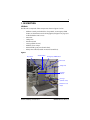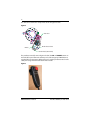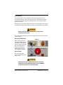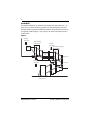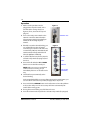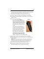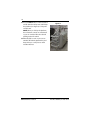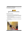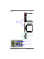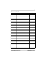
1
OMEGA Curved Inclined Platform Lift OWNER’S MANUAL (To Be Retained by Owner After Installation by Authorized Savaria Dealer) Part No. 000825 14-m05-2014 2 IMPORTANT Ensure that only an authorized Savaria Dealer installs and services the OMEGA Curved Incline Platform Lift. Under no circumstances is anyone other than a Dealer with Savaria training and authorization to install, adjust, service or modify any mechanical or electrical device on this equipment. Failure to follow this warning can result in safety system compromises or defeat; this can result in serious injury or death. Savaria Corporation accepts no liability for property damage, warranty claims or personal injury, including death, in this circumstance. Passenger safety is the result of countless details in the equipment design, manufacture, and installation. After installation, reliable operation and continual safe operation requires regular inspection and maintenance as outlined in this manual, or more frequently where usage, environment, or local jurisdiction requires. As the Owner, you are responsible for ensuring that regular inspections and maintenance occur in a timely manner. Refer to this manual for unit description, setup, operating instructions, and a maintenance schedule for the OMEGA Curved Incline Platform Lift. Upon completion of installation, the Dealer must provide you with the following information and ensure it is recorded in this manual. In addition, either the Dealer or yourself must keep any service and/or maintenance records in the Maintenance Record section of this manual. WARRANTY Ensure your Savaria Dealer provides you with a copy of the manufacturer’s limited parts warranty and documentation relating to any Dealer labour warranty. ------------------------------------------------------------------------------------------------FOR OWNER’S RECORDS Customer Name: _______________________________________ Installing Dealer: _______________________________________ Dealer’s Telephone Number: _____________________________ Date Installed: _________________________________________ Serial/Job Number: _____________________________________ OMEGA Owner’s Manual Part No. 000825, 14-m05-2014 3 Table of Contents TO ENSURE SAFE OPERATION . . . . . . . . . . . . . . . . . . . . . . . . . . . . . . . . . . . . . . . . . . . . . . 4 1. DESCRIPTION . . . . . . . . . . . . . . . . . . . . . . . . . . . . . . . . . . . . . . . . . . . . . . . . . . . . . . . . . . . 5 Lift Unit . . . . . . . . . . . . . . . . . . . . . . . . . . . . . . . . . . . . . . . . . . . . . . . . . . . . . . . . . . 5 Guide Rails . . . . . . . . . . . . . . . . . . . . . . . . . . . . . . . . . . . . . . . . . . . . . . . . . . . . . . . . 8 Safety Features . . . . . . . . . . . . . . . . . . . . . . . . . . . . . . . . . . . . . . . . . . . . . . . . . . . 9 2. SPECIFICATIONS . . . . . . . . . . . . . . . . . . . . . . . . . . . . . . . . . . . . . . . . . . . . . . . . . . . . . . .11 3. PROPER AND IMPROPER USE . . . . . . . . . . . . . . . . . . . . . . . . . . . . . . . . . . . . . . . . . . .12 Proper Use . . . . . . . . . . . . . . . . . . . . . . . . . . . . . . . . . . . . . . . . . . . . . . . . . . . . . .12 Improper Use . . . . . . . . . . . . . . . . . . . . . . . . . . . . . . . . . . . . . . . . . . . . . . . . . . .12 4. OPERATION . . . . . . . . . . . . . . . . . . . . . . . . . . . . . . . . . . . . . . . . . . . . . . . . . . . . . . . . . . . .13 Warnings . . . . . . . . . . . . . . . . . . . . . . . . . . . . . . . . . . . . . . . . . . . . . . . . . . . . . . .13 Operation . . . . . . . . . . . . . . . . . . . . . . . . . . . . . . . . . . . . . . . . . . . . . . . . . . . . . . .14 Manual Operation in an Emergency . . . . . . . . . . . . . . . . . . . . . . . . . . . . . .17 5. TROUBLESHOOTING . . . . . . . . . . . . . . . . . . . . . . . . . . . . . . . . . . . . . . . . . . . . . . . . . . .20 6. MAINTENANCE . . . . . . . . . . . . . . . . . . . . . . . . . . . . . . . . . . . . . . . . . . . . . . . . . . . . . . . .21 Maintenance Record . . . . . . . . . . . . . . . . . . . . . . . . . . . . . . . . . . . . . . . . . . . .23 Part No. 000825, 14-m05-2014 OMEGA Owner’s Manual 4 TO ENSURE SAFE OPERATION To ensure safe operation of this unit, pay careful attention to the important notes below. WARNING This symbol accompanies essential safety instructions. Follow these instructions and any additional safety regulations. IMPORTANT • Read this manual carefully before using the platform lift. • To prevent accidents, adhere strictly to the instructions and keep clear of moving parts at all times. • Never exceed the maximum load capacity as indicated on the side of the carriage. • Passengers must remain in the wheelchair or seated while the lift is operating. • Follow instructions on all equipment labels at all times. Replace any damaged labels immediately. • Ensure that only qualified personnel perform maintenance and service on the unit. • This unit is intended for use by an adult that understands its proper operation as set out in this manual. WARNING Wheelchair users on the platform must ALWAYS ride facing in the direction of travel. Users without a wheelchair must ride sitting down on the seat and wearing the safety belt. OMEGA Owner’s Manual Part No. 000825, 14-m05-2014 5 1. DESCRIPTION Lift Unit The lift unit is comprised of the components shown in Figure 1 below. • • • • • • • • Platform control panel which has a key switch, an emergency STOP button, an alarm button and a running light (see Figure 4 on page 7) to indicate that the unit is in use Drive unit Safety arms Pendant control Carriage (behind cover) Platform access ramps Manual folding seat (not shown below) Main power switch (located on external control box) Figure 1 Key switch Alarm button Emergency STOP button Drive unit Safety arms Pendant control Carriage (behind cover) Platform access ramps Part No. 000825, 14-m05-2014 OMEGA Owner’s Manual 6 The drive unit contains the components shows in Figure 2 below. Figure 2 Gear box Motor Brake release lever Handwheel (removable) The pendant control (shown in Figure 3 below) has UP and DOWN buttons to move the lift up and down the stairway and a red emergency STOP button to stop the lift in an emergency. When not in use, hang the pendant control on the safety arm using the hook at the back of the control. Figure 3 OMEGA Owner’s Manual Part No. 000825, 14-m05-2014 7 Control Buttons The control buttons on the pendant and at the landing call stations are constant-pressure type. This means you must press and hold the button to operate it. Release the button to stop the function. The emergency STOP button is push/pull. Note that you need a key to activate the controls on the platform control panel and at the landing call station (if the call station is equipped with a key switch). WARNING Never use the lift if the control buttons do not work in constant-pressure mode. The landing call/send stations are hard-wired with up, down, fold and unfold control buttons. Emergency STOP Button When you press the red emergency STOP button on the platform control panel (shown in Figure 4), the lift will stop immediately. To release the emergency STOP button, press and turn it slightly clockwise. Figure 4 Alarm button Running light Running Light The red running light flashes to indicate that the unit is in use. WARNING Check the emergency STOP button operation weekly. If the lift does not stop when the button is pressed, DO NOT use the lift. Contact your authorized dealer. Part No. 000825, 14-m05-2014 OMEGA Owner’s Manual 8 Guide Rails The platform lift travels up and down the stairway along two guide rails – an upper rail and a lower rail. If the gradient is less than 20 degrees, a third rail (horizontal rail) is required to stabilize the platform. Horizontal rail sections may be required at half-landings or stop positions. A sample installation layout is shown below. Figure 5 Landing call station Upper landing stop position Landing call station Intermediate landing stop position Carriage Drive Horizontal rail Upper rail Landing call station Lower rail Lower landing stop position OMEGA Owner’s Manual Part No. 000825, 14-m05-2014 9 Safety Features The lift has the following safety features: • • • • • • • Safety arms Platform ramps Obstruction sensors Drive with self-locking gear and safety brake Overspeed governor Limit switches Audio visual alarm (running buzzer and light) Safety Arms and Platform Ramps While in motion, the platform is protected by two safety arms. The platform is also protected by two ramps which have the dual function of facilitating access to the lift at the landings and of retaining the wheelchair while the lift is in motion. Before the lift leaves the floor, the safety arms must be down and the platform access ramps must be up. If the safety arms or platform ramps encounter an obstacle as they move into position, a microswitch is tripped, preventing operation of the lift until the obstacle is removed. Obstruction Sensors During travel, the edges of the platform ramps and the carriage are protected by sensors which stop the lift if it touches any obstacle. There are also safety underpan sensors to detect any obstacle underneath the platform and carriage and stop the lift. Safety Brake (Overspeed) The lift is equipped with a mechanical safety brake. It engages if a drive component fails or if the normal downward travel speed is exceeded by a preset amount. Application of the brake slows the lift to a stop. WARNING When the safety brake engages, the lift remains locked out of use. Contact your authorized dealer to release the brake and return the lift to normal operation. Part No. 000825, 14-m05-2014 OMEGA Owner’s Manual 10 Limit Switches The upper and lower limit switches allow the lift to stop automatically in the correct position at the upper or lower end of the staircase. If the upper or lower limit switch fails, the final safety limit switch stops the unit. WARNING If the lift is unable to move after it stops, contact your authorized dealer to return the lift to normal operation. Audio Visual Alarm There is an audio visual alarm to indicate that the unit is running. This includes a buzzer and a red running light on the platform control panel that flashes when the unit is in use. See Figure 4 on page 7. OMEGA Owner’s Manual Part No. 000825, 14-m05-2014 11 2. SPECIFICATIONS Performance Travel direction Forward/backward Travel length Up to 164 feet (50 metres) Speed (up/down) 14 feet/minute (0.07 metres/second) Capacity 1 person in a wheelchair or sitting on the manual folding seat; seat capacity is 330 lb (150 kg) Maximum load 550 lb (250 kg) Gradient Variable up to 55° Environmental Conditions Temperature -31°F to +113°F (-35°C to +45 °C) Noise Less than 70 db Power supply 240V (+/-5%), single-phase, 60 Hz Motor 1 hp (0.75 kW), 2.2 kW over 30 m Controls Pendant control buttons Two drive buttons used to move the lift up or down the stairway and one emergency STOP button Call station controls Used to call/send the lift, fold/unfold the platform (for automatic platform); has an optional key switch to enable controls Platform control panel Emergency STOP button to bring the lift to an immediate stop Key switch to enable controls Alarm button to signal for help Running light that flashes to indicate the unit is in use Part No. 000825, 14-m05-2014 OMEGA Owner’s Manual 12 3. PROPER AND IMPROPER USE Proper Use The OMEGA lift is an accessibility device used to provide access over straight-run stairs with a constant gradient. The lift will transport a passenger either sitting in a wheelchair or on the manual folding seat. The lift is designed for use by a self-sufficient person with knowledge of the unit’s operation and general maintenance instructions. NOTE If the person using the lift is not self-sufficient, it must be operated by an attendant. Always remain still while the lift is in motion. Do not use the lift when someone else is using the stairway. WARNING Wheelchair users on the platform must ALWAYS ride facing in the direction of travel. Users without a wheelchair must ride sitting down on the seat and wearing the safety belt. Improper Use • Do not transport objects on the platform. • Do not transport more than one person at a time. • Do not stand on the platform. • Do not overload the lift. • Do not spray any liquids onto the lift or rails. • Do not make any modifications to the lift. WARNING For your safety, use the lift only as intended. OMEGA Owner’s Manual Part No. 000825, 14-m05-2014 13 4. OPERATION WARNING For your safety, read this manual before using the lift and always use the lift only as intended. Warnings • Ensure there is unrestricted access to the platform and the main power switch in the external control box. • Never overload the platform. • While on board the lift, always remain seated with the wheelchair brakes on. If the wheelchair is electric, turn it off as long as the lift is moving. Keep your feet on the wheelchair footrest. • Note that in some installations where there is low overhead, you may have to reposition yourself on the platform to avoid contacting the ceiling • If using the manual folding seat, make sure the seat belt is securely fastened. Be sure to fold up the seat after use. • While on board the lift, always look in the direction of travel and stop the lift immediately if there is anyone on the travel route. • During operation of the lift, the landings and travel route must always be illuminated. • Keep the platform key in a safe storage place for access by authorized personnel only. Be sure to remove the key after each use. • Never leave the lift halfway up the staircase. • Never use the lift unless a trained person is available to operate it in manual mode in an emergency situation. • Never place your hands or any objects close to the rails or the platform while the lift is in motion. Part No. 000825, 14-m05-2014 OMEGA Owner’s Manual 14 Operation 1 Make sure the pendant control is plugged into the jack located on the side wall of the carriage body (see Figure 6). If not, unscrew the cap and plug it in. Figure 6 PENDANT JACK 2 Turn on the main power switch on the external control box. Note that when the main power switch is turned off, you cannot run the lift using any of the controls. 3 If the lift is not at the desired landing, you can call the lift using the call station controls (Figure 7 shows a call station for an automatic platform). Note that the call station controls will only control the lift when the platform is folded up. Figure 7 UP DOWN 4 To call the lift, first insert the key into the call station key switch (if equipped) and turn it on. FOLD 5 Press and hold either the UP or DOWN button to move the lift towards you. UNFOLD NOTE: Make sure you can see the lift at all times when it is moving; stop it immediately if there is an obstacle in the way. KEY SWITCH (OPTIONAL) 6 The lift will stop automatically at the desired landing. In the event that the lift does not stop after releasing the control button, you can turn off the call station key switch (if equipped) to stop travel. 7 Press and hold the UNFOLD button on the call station to lower the platform and raise the safety arm. The access ramp will lower automatically. Be careful of the moving parts. 8 If using the manual folding seat, fold down the seat. 9 Turn off and remove the key from the call station key switch (if equipped). OMEGA Owner’s Manual Part No. 000825, 14-m05-2014 15 10 Drive the wheelchair onto the platform and park it so that no part of the passenger’s body or the wheelchair projects from the platform. Engage the wheelchair brakes. If the wheelchair is electric, turn it off. If using the manual folding seat, be sure to fasten the seat belt. 11 Lower the safety arm and the access ramp will lift up automatically. 12 Insert the key into the platform key switch and turn it on to activate the platform controls. 13 To travel up or down the stairs: Figure 8 • Press either the UP or DOWN drive button on the pendant control (shown in Figure 8) to drive the lift to the desired landing. Note that the safety arms remain down and the access ramps remain up in the locked position as long as the lift is in motion. • The lift will stop automatically at all landings. If you keep the drive button pressed at an intermediate stop, the lift will stop briefly and then continue travelling towards the next landing. • If you need to stop the lift along the travel route for any reason, release the drive button. If this does not work, press the red emergency STOP button on the platform control panel or the handheld pendant. 14 When the lift reaches the desired landing, it stops automatically. 15 Keep the drive button pressed until the safety arm is raised and the exit ramp is lowered. NOTE: If there is an acoustic signal 5 seconds after releasing the drive button, then the lift is probably not in the exact recharging position. Reactivate the drive button to bring the lift to the exact position. 16 Turn off and remove the key from the platform key switch. 17 Disengage the wheelchair brakes and drive off the platform. If the manual folding seat was used, release the seat belt. Part No. 000825, 14-m05-2014 OMEGA Owner’s Manual 16 18 Press the FOLD button on the call station to fold down the safety arms and fold up the platform (see Figure 9). Fold up the seat by hand. Figure 9 NOTE: When you fold up the platform, the call station controls are reactivated so you can send the lift to the desired parking station if needed. 19 When the lift is not in use, be sure to switch if off with the platform key and keep the key in a safe place to avoid unauthorized use. OMEGA Owner’s Manual Part No. 000825, 14-m05-2014 17 Manual Operation in an Emergency You can use manual operation to bring the lift to the next landing in the event of a power failure or equipment breakdown. WARNING Before proceeding with manual operation, you MUST switch off the main power switch on the external control box. Moving the Lift in an Emergency 1 Switch off the main power switch on the external control box. 2 Push back the small lever protruding from the handwheel access hole in the bottom of the drive unit cover. Install the handwheel on the motor shaft (see Figure 10 below). NOTE that you can also use an electric drill with the provided adapter for faster lowering. 3 Push down and hold the brake release lever. Turn the handwheel in the desired direction until the closest landing has been reached. Note that this process is very slow. 4 Release the brake lever and remove the handwheel. Store the handwheel in an easily accessible place. Figure 10 Brake release lever Handwheel Part No. 000825, 14-m05-2014 OMEGA Owner’s Manual 18 5 Lift up the safety arm and assist the passenger off the platform. NOTE: If you are unable to drive the lift to the next landing, you will need to release the safety arms as described in the procedure below. 6 Lock the platform with the padlock on the carriage. 7 Contact your authorized dealer if repair to the lift is required. 8 To operate the lift again, turn on the main power switch on the external control box. Releasing the Safety Arms in an Emergency 1 To release a safety arm, press and hold the upper landing arm release lever located at the back of the carriage (see Figure 11 on the next page). • To release the left safety arm (as viewed from the front of the unit), press the upper lever. • To release the right safety arm (as viewed from the front of the unit), press the lower lever. • Note that this is the same for a left- or a right-hand unit. WARNING Be very careful not to release the downside safety arm and put the passenger in danger. 2 While pressing and holding the appropriate lever, release the safety arm by pulling abruptly. OMEGA Owner’s Manual Part No. 000825, 14-m05-2014 19 Figure 11 SIDE VIEW Arm release levers at back of platform TOP VIEW EXPLODED VIEW Upper lever for left arm Lower lever for right arm Part No. 000825, 14-m05-2014 OMEGA Owner’s Manual 20 5. TROUBLESHOOTING For safety reasons, the lift is equipped with several electrical and mechanical locking devices. The lift will not work if any of these devices is tripped or if the order of events is incorrect. WARNING Only qualified technicians are authorized to perform repairs and 6-month maintenance. DO NOT manipulate, modify or remove any safety feature of the lift. Contact your authorized dealer as necessary. Follow through the items below to determine a possible reason for the problem before contacting your authorized dealer. 1 If you’re having a problem with a call station, note the following: • When the controls at one call station are activated, all other call stations are automatically deactivated. The lift can only be controlled by one control at a time. • The platform must be folded up for the call station controls to function. • Check that the key switch (if equipped) on the call station is turned on. 2 If the lift will not move, check the following: • Check that the main power switch on the external control box is turned on. Turn on the platform key switch and make sure the green lamp on the platform turns on. • Check that there are no blown fuses in the building power distribution box. • Check that all emergency STOP buttons are released. • Check for obstacles underneath the access ramps and platform. If the problem persists, contact your authorized dealer for assistance. OMEGA Owner’s Manual Part No. 000825, 14-m05-2014 21 6. MAINTENANCE Periodic checks and maintenance are necessary to ensure your safety and proper operation of the lift. Refer to the table below for a list of checks and maintenance items. WARNING To ensure your safety and proper operation of the lift, be sure to check the items below that are identified as WEEKLY. Contact your authorized dealer to perform 6-month maintenance and repairs. MAINTENANCE SCHEDULE ITEM TO BE CHECKED FREQUENCY BY OPERATOR Check that the lift does not start moving until the safety arms are down and the access ramps are up in the safety position. Monthly Check that the safety arms and ramps remain closed while travelling. Monthly Verify that the safety arms cannot be lifted up when you are travelling between two landings. Monthly Verify that the lift stops immediately when the emergency STOP button is pressed. Monthly Verify that the lift stops at every landing. Monthly Verify that the lift stops when the directional drive button is released. Monthly Verify that the lift stops immediately if the ramp runs into an obstacle. Monthly Verify that the lift stops immediately if an obstacle is detected underneath the platform. Monthly Use a dry clean cloth to clean the outside of the rail tubes. As required Ensure clear access to the drive and main power switch in the external control box. As required Part No. 000825, 14-m05-2014 OMEGA Owner’s Manual 22 BY AUTHORIZED DEALER Verify proper operation of all limit switches. Every 6 months Check the tension in the drive cable and adjust if required. Every 6 months Check that the drive sprocket teeth and the nylon rollers on which the lift runs are not worn or damaged. There must be no scoring or flattening of the rollers. Every 6 months Verify proper operation of the safety brake (overspeed governor). Every 6 months Check that all fixing screws on the rails and carriage are present and securely fastened. Every 6 months Check all moving parts, covers, signs, and labels. Every 6 months Clean the rail thoroughly. Every 6 months Verify proper operation of the pendant control buttons. Every 6 months Verify proper operation of the call station control buttons. Every 6 months Check that all electrical components, contactors and microswitches are operating correctly. Check the condition of all cables. Check the grounding. Every 6 months NOTE Units installed in adverse environments will require additional maintenance on a monthly basis. OMEGA Owner’s Manual Part No. 000825, 14-m05-2014 23 Maintenance Record Date and time Reason for call (other comments) Part No. 000825, 14-m05-2014 Dealer OMEGA Owner’s Manual Authorized Savaria Dealer OMEGA Curved Inclined Platform Lift OWNER’S MANUAL Part No. 000825 Copyright2014 Savaria Corporation Elevators and Lifts www.savaria.com Sales 2 Walker Drive Brampton, Ontario, L6T 5E1, Canada Tel: (905) 791-5555 Fax: (905) 791-2222 Toll Free: 1-800-661-5112