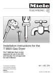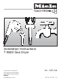
1
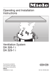
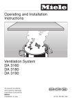
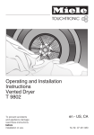
Installation Instructions
T 9822 Gas Dryer
To prevent accidents
and appliance damage
read these instructions
before
installation or use.
en - US, CA
M.-Nr. 07 431 110
2
,WARNING
For your safety the information in this manual
must be followed to minimize the risk of fire or
explosion or to prevent property damage,
personal injury or death.
– Do not store or use gasoline or other flammable
vapors and liquids in the vicinity of this or any
other appliance.
– WHAT TO DO IF YOU SMELL GAS
ß Do not try to light any appliance.
ß Do not touch any electrical switch.
ß Do not use any phone in your building.
ß Clear the room, building or area
of all occupants.
ß Immediately call your gas supplier from a
neighbor’s phone. Follow the gas supplier’s
instructions.
ß If you cannot reach your gas supplier,
call the fire department.
– Installation and service must be performed by a
qualified installer, service agency or the gas
supplier.
(In Massachusetts a licensed plumber / gas fitter.)
3
Contents
IMPORTANT SAFETY INSTRUCTIONS. . . . . . . . . . . . . . . . . . . . . . . . . . . . . . . . . 5
Installation . . . . . . . . . . . . . . . . . . . . . . . . . . . . . . . . . . . . . . . . . . . . . . . . . . . . . . . 7
Stand . . . . . . . . . . . . . . . . . . . . . . . . . . . . . . . . . . . . . . . . . . . . . . . . . . . . . . . . . . . . 7
Installation site . . . . . . . . . . . . . . . . . . . . . . . . . . . . . . . . . . . . . . . . . . . . . . . . . . . . 9
Installation . . . . . . . . . . . . . . . . . . . . . . . . . . . . . . . . . . . . . . . . . . . . . . . . . . . . . . 11
Transporting the dryer to the installation site. . . . . . . . . . . . . . . . . . . . . . . . . . . . . 11
Level the dryer . . . . . . . . . . . . . . . . . . . . . . . . . . . . . . . . . . . . . . . . . . . . . . . . . . . . 11
Determining the position of the exhaust connection . . . . . . . . . . . . . . . . . . . . . . . 12
Electrical connection . . . . . . . . . . . . . . . . . . . . . . . . . . . . . . . . . . . . . . . . . . . . . . 13
Gas connection . . . . . . . . . . . . . . . . . . . . . . . . . . . . . . . . . . . . . . . . . . . . . . . . . . 14
Ducting . . . . . . . . . . . . . . . . . . . . . . . . . . . . . . . . . . . . . . . . . . . . . . . . . . . . . . . . . 18
How to calculate the effective duct length . . . . . . . . . . . . . . . . . . . . . . . . . . . . . . 19
Exhaust connection with a flexible exhaust hose or rigid pipe . . . . . . . . . . . . . . . 23
Direct wall connection . . . . . . . . . . . . . . . . . . . . . . . . . . . . . . . . . . . . . . . . . . . . . . 25
Caring for the environment . . . . . . . . . . . . . . . . . . . . . . . . . . . . . . . . . . . . . . . . . 26
4
IMPORTANT SAFETY INSTRUCTIONS
Installation and connection
~ GROUNDING INSTRUCTIONS
~ To reduce the risk of severe injury or
death, follow all installation instructions.
This appliance must be grounded. In
the event of malfunction or breakdown,
grounding will reduce the risk of
electric shock by providing a path of
least resistance for electric current. This
appliance is equipped with a cord
having an equipment grounding
conductor and a grounding plug. Only
place the plug in an appropriate outlet
that is properly installed and grounded
in accordance with all local codes and
ordinances.
~ Clothes dryer installation must be
performed by a qualified installer.
~ WARNING – Improper connection of
, WARNING - Risk of Fire
When using your gas appliance
follow basic safety precautions
including the following:
~ It is essential to read all instructions
before installing the appliance.
~ Install the clothes dryer according to
the manufacturer's instructions and
local codes.
~ Repair and maintenance work
should be performed by a qualified
installer, service agency or the gas
supplier. Work by unqualified persons
could be dangerous and could void the
warranty.
~ In Massachusetts:
This dryer must be installed by a
licensed plumber or gas fitter.
~ Before installation, disconnect the
tumble dryer from the electrical supply
by shutting off the power main,
unplugging the power cord or tripping
the circuit breaker. Do not restore
power until the installation is complete.
the equipment grounding conductor
can result in a risk of electric shock.
Check with a qualified electrician if you
are in doubt as to whether the
appliance is properly grounded.
~ Do not modify the plug provided
with the appliance! If it will not fit the
outlet, have a proper outlet installed by
a qualified electrician.
~ Do not use an extension cord to
connect this appliance to the power
supply. Extension cords do not
guarantee the required safety of the
appliance (e.g. danger of overheating).
~ This dryer must be vented outdoors
to reduce the risk of fire. Be sure to
observe local building codes.
~ Use flexible or rigid metal pipe for
venting. Non-metallic flexible hose
should not be used, it is a potential fire
hazard.
5
IMPORTANT SAFETY INSTRUCTIONS
~ Do not install a clothes dryer with
flexible plastic venting materials. If
flexible metal (foil type) duct is
installed, it must be of a specific type
identified by the manufacturer as
suitable for use with clothes dryers.
Flexible venting materials are known to
collapse, be easily crushed, and trap
lint. These conditions will obstruct
clothes dryer airflow and increase the
risk of fire.
~ The appliance shall not be
exhausted into a chimney, a wall, a
ceiling, an attic, a crawl space, or a
concealed space of a building.
~ Do not install the appliance in rooms
where temperatures below freezing
may occur.
~ Proper installation is the
responsibility of the installer.
~ Product failure due to improper
installation is not covered under the
Warranty.
~ Gas dryers are not approved for
mobile home installation.
~ If there is any doubt concerning
installation, contact Miele’s Technical
Service Department.
U
1-800-999-1360
[email protected]
V
1-800-565-6435
[email protected]
SAVE THESE
INSTRUCTIONS
6
Installation
Front view
a Exhaust connection
Stand
b Power cord with plug
A dryer stand, with drawer, can be
purchased as an optional accessory.
c Control panel
d Door
e Four height adjustable screw feet
7
Installation
Rear
a Handle for transportation (arrows)
b Power cord with plug
c Slot for module
d Air intake
e Gas connection
f Exhaust connection with restriction
insert
8
,WARNING : Do not remove the
restriction insert in the vent
opening. It may result in poor drying
results, damage to the laundry and
higher Carbon monoxide emissions.
Exception: The restriction insert
must be removed if the exhaust
connection if moved to the left or
right side of the dryer.
Installation site
,WARNING:
Do not install the dryer:
- outdoors
- in an environment with dripping
water or weather
- near flammable materials
- in rooms which may contain gas
or other fuels
- in closets with solid doors
- with other fuel-burning
appliances in the same closet
, The National Fuel Gas Code
restricts installations of gas
appliances in garages. They must
be 18 inches off the ground and
protected by a barrier from
vehicles.
,If the appliance is installed on a
raised platform it must be secured
with retaining clips available from
your dealer or miele.
If installed on a masonry or concrete
base, the base should have a ½"
(13 mm) to 3/4" (19 mm) high rim.
This must be done to prevent the
dryer from vibrating off the base.
- in a location where its door
could conflict with room doors.
- next to a refrigerator
- under a countertop
- on top of a washer.
9
Installation site
Confined space installation
Minimum installation clearance
^ When installed in any space with less
than 122 square feet (11.3 m2),
minimum clearances around the
dryer must be adhered to for proper
ventilation and vents for make up air
must be installed.
^ Do not install any other fuel-burning
appliance in the same space as the
dryer.
Confined door openings
Any doors limiting circulation must be
louvered or otherwise ventilated.
A minimum of 72 square inches
(465 cm2) of opening is required. It
must be equally divided within 3"
(7.6 cm) from the top and bottom of the
door.
Sides: 0 " (0 cm)
Top:
12" (30.5 cm)
Rear: 0" (0 cm) (as close to wall as
gas connection and venting allows)
Front to door: 2" (5 cm)
Make sure the dryer door can open
completely once installed.
Exhaust duct clearance
to combustible material: 2" (5 cm)
10
Installation
Transporting the dryer to the
installation site
Level the dryer
The rear of the lid has a handle for
transportation.
^ Use the front dryer feet and the rear
of the lid to move the dryer to the
installation site.
The dryer must be level to ensure safe
and proper operation.
^ Unscrew the four feet as necessary
by turning the foot, 1, and the locking
nut, 2, to the left.
^ Once level, hold the foot, 1, still with
adjustable pliers. At the same time,
turn the locking nut, 2, to the right
using a wrench.
,The dryer lid cannot be
removed.
11
Installation
,WARNING
Before installation, disconnect the
tumble dryer from the electrical
supply by shutting off the power
main or tripping the circuit breaker.
Be sure the dryer power cord is
unplugged from the wall.
Do not restore power until the
installation is complete.
Turn the dryer’s gas shutoff valve in
the supply line to the OFF position.
,WARNING
With left or right exhaust
connections, the restriction insert
must be integrated into the side
exhaust ducting guide.
Otherwise poor drying results,
damage to the laundry and higher
Carbon monoxide emissions may
occur.
^ Place the restriction insert into the
adapter (see "Exhaust connection
with a flexible exhaust hose or rigid
pipe").
Disconnect and discard old flexible
gas connector and ducting material.
Determining the position of the
exhaust connection
The exhaust connection can be left at
the rear of the dryer (factory standard)
or moved to the left or right side.
Changing the position of the exhaust
connection
^ Remove the exhaust connection
cover on the left or right side of the
dryer by turning it counterclockwise
and take it out.
^ Firmly press the cover into the rear
exhaust connection.
^ Remove the restriction insert.
12
Electrical connection
,GROUNDING INSTRUCTIONS
This appliance must be grounded.
In the event of malfunction or
breakdown, grounding will reduce
the risk of electric shock by
providing a path of least resistance.
This appliance is equipped with a
cord having an equipment
grounding conductor and a
grounding plug. The dryer, when
installed, must be electrically
grounded in accordance with local
codes, or in the absence of local
codes, with the National Electrical
Codes ANSI/NFPA 70, or the
Canadian Electrical Code, CSA
C22.1.
The dryer is supplied with a 5’ 7"
(1.7 m) 3x14 AWG cord and a
NEMA 5-15 P plug, ready for
connection to a 120 V, 60 Hz, 15 A AC
power supply.
^ Plug the machine into a proper outlet.
If the plug does not fit, have a proper
outlet installed by a qualified
electrician.
WARNING – Improper connection of
the equipment grounding conductor
can result in a risk of electric shock.
Check with a qualified electrician,
service representative or personnel
if you are in doubt as to whether the
appliance is properly grounded.
,WARNING – This dryer is
equipped with a three-prong
(grounding) plug for your protection
against shock hazard and should be
plugged directly into a properly
grounded three-prong receptacle.
Do not cut or remove the grounding
terminal from this plug.
Do not modify the plug! If it will not
fit the outlet, have a proper outlet
installed by a qualified electrician.
13
Gas connection
,WARNING
Installation and service must be
performed by a qualified installer,
service agency or gas supplier.
In Massachusetts a licensed
plumber / gas fitter is required.
This appliance must be installed
with its own shut off valve in the
same room. The valve must be
easily accessible to the consumer to
turn on or shut off the gas supply
after the appliance is installed.
During any pressure testing of the
gas system this appliance must be
disconnected from the gas supply
by closing its individual manual shut
off valve.
Any pipe connections must be made
using a thread sealant approved for
gas connections. Failure to correctly
install these items could lead to a
gas leak and subsequent explosion.
The gas installation must be made in
accordance with local codes or, in
the absence of local codes, with
-
National Fuel Gas Code,
ANSI Z223.1/NFPA 54 for USA
or
- Natural Gas and Propane
Installation Code,
CSA B149.1 for Canada.
14
Gas type
The gas dryer is equipped for
connection to a NATURAL GAS
supply.
The maximum heat output is
19,500 BTU/H (5,7 kW).
Minimum gas supply pressure
to obtain the required gas input is:
0.15 psi (4" WC) for natural gas
0.29 psi (8" WC) for LP gas.
Maximum gas supply pressure
before the gas pressure regulator
0.37 psi (10" WC) for natural gas
0.46 psi (13" WC) for LP gas.
Gas connection
Gas supply
Installation material (hoses and
adapters) must be provided by the
installer.
Gas connection distances
a Flare union adapter
b 1/8" NPT pressure tapping plug
c Gas shut-off valve
This appliance must be installed with its
own shut off valve on the gas supply
line. The valve must be within 6 ft.
(1.8 m), and in the same room, of the
dryer.
For convenience (if allowed by code),
an AGA or CGA approved flexible
stainless steel gas hose (accordion
type) may be used between the gas
shut-off valve and the dryer. This will
allow the appliance to be moved from
the installation site for cleaning or
servicing. Make sure that nothing rubs
on the gas hose.
An 1/8" NPT pressure tapping plug
must be installed immediately upstream
of the gas supply connection. This
allows the gas inlet pressure to be
checked.
If there is any doubt concerning
installation, contact the Miele Technical
Service Department at the phone
number listed on the back of this
manual.
15
Gas connection
,To secure all connections use
appropriate Teflon tape or a thread
compound, suitable for gas
connections.
^ Install a 3/8" flare union adapter, a, to
the female elbow, b.
Hold the elbow with a wrench.
^ At the end of the dryer's gas
connection hand screw on the
3
/8" NPT elbow.
Using a wrench tighten the elbow
with a half turn.
,DO NOT OVERTIGHTEN.
^ Secure the flexible metal gas line
connector to the adapter.
16
Gas connection
^ Using two wrenches tighten the
flexible gas line connection.
^ Using two wrenches tighten all
connections.
,DO NOT OVERTIGHTEN.
^ Connect the flare union adapter, a,
to the pressure tapping plug, b,
originally installed on the gas shut off
valve, c.
^ Open the gas shut-off valve.
^ After connecting the appliance
check all fittings for gas leaks e.g.
with soapy water or an equivalent.
,WARNING
NEVER USE AN OPEN FLAME TO
TEST FOR GAS LEAKS.
17
Ducting
Exhaust ducting and
connections
A gap of 3/8" (10 mm) must be
provided between the appliance
and the floor. This gap is necessary
for proper air flow and must not be
blocked by a toe-kick or thick piled
carpets.
Sufficient venting of the installation
site is essential for proper dryer
operation. Inadequate ventilation will
increase energy use and drying
times.
Do not install the dryer next to a
refrigerator. The heat emanating
from the dryer can affect the
thermostat of the refrigerator,
causing it to run continuously.
18
,WARNING
Danger of toxic fumes.
The exhaust gases from the dryer
must only be vented outside the
building.
DO NOT terminate the exhaust
ducts in a chimney, fireplace
ducting, a combustion appliance
vent flue, or enclosed,
unventilated area such as attics,
garages, crawlspaces, walls,
ceilings or concealed space of a
building.
To reduce the risk of fire, only use
metal ductwork.
Ducting
How to calculate the effective
duct length
The overall duct length will determine
the duct diameter (see the "Additional
duct lengths" table). In Canada the
exhaust duct must be 4" (102 mm) in
diameter.
^ Measure the actual duct length
needed to go from the dryer’s
exhaust connection to the vent outlet:
1. Establish the number of elbows or
bends necessary, noting the type of
bend, angle and radius involved
(see the "Additional duct lengths"
table).
2. Add the additional duct length (as
derived by using the values
specified in the "Additional duct
lengths" table) to the actual duct
length to get the effective length.
Note:
Maximum effective duct lengths:
4" (100 mm) diameter
66 ft (20 m)
5" (125 mm) diameter
115 ft (35 m)
6" (150 mm) diameter
108 ft (33 m)
* For rigid ducting only!
Local building codes may vary.
When flexible metal duct (transition
duct) is permissible by local building
codes, the total length must not
exceed 7' 10" (2.4 m).
See the "Additional duct lengths"
table for more information on
maximum duct lengths and number
of bends.
Effective duct lengths over 66 ft (20 m)
require a larger duct diameter.
Longer ducts may lead to decreases in
dryer efficiency if the next larger duct
diameter is not followed.
19
Ducting
Tips about the ductwork
– Check with your local building code
to determine the maximum allowable
duct length.
– Only use rigid or flexible metal duct
for exhausting. Non-metallic flexible
hose should not be used, it is a
potential fire hazard.
– Rigid metal or flexible aluminum
ducting is preferred. Flexible foil
ducting may move and bounce due
to the high airflow of the dryer. This
could lead to a thumping or grinding
noise.
– Non-metallic flexible hose should not
be used. It is a potential fire hazard.
– In the United Stated foil-type flexible
ducts should only be used if
identified for use by the manufacturer
as compliant with the Outline for
Clothes Dryer Transition Duct,
Subject ANSI/UL 2158A.
In Canada, only flexible metal
(foil-type) ducts specifically identified
for use by the manufacturer should
be used.
– For best drying results avoid extra
long ducting with too many bends,
angles or tight corners.
20
– Do not assemble the duct with
screws or other fastening devices
that extend into the duct and catch
lint.
– The shorter the exhaust ductwork,
the more efficient the dryer will be.
Expelled air is slowed down in the
ducts due to friction against the inner
walls. The shorter and smoother the
inner walls are, the less friction will
be created.
– An elbow or bend creates more
friction than a straight duct. An
additional duct length factor must be
added for each elbow or bend (see
Table). This factor expresses the
resistance of the bend in terms of a
straight length of duct.
The additional length factor is then
added to the existing duct to give the
effective duct length.
A larger duct diameter helps to
reduce friction. Therefore duct
diameter should be increased if
longer duct lengths are required.
Ducting
Additional duct lengths (4" [100 mm] rigid pipe only)
Type of bend
Radius
Additional duct length
inches
cm
ft
cm
Flexible metal duct
– 3’ 3" (1 m) straight
– 45° angle
– 90° angle
10"
10"
25
25
5’ 11"
4’ 11"
8’ 2"
180
150
250
Smooth metal duct
– 3’ 3" (1 m) straight
– 45° angle
– 90° angle
10"
10"
25
25
3’ 3"
1’ 11"
2’ 7"
100
60
80
7’ 6"
230
2’ 4"
70
12’ 5"
4’ 11"
19’ 8"
380
150
600
Elbow 90° sharp
Concertina bend
– 90° angle
Wall vent or window vent
– with louvers
– with flap
– with weather hood
8"
20
21
Ducting
Example
Rigid pipe
Duct length
ft
Duct length
m
A
Wall duct with louvered
wall vent
12’ 5"
3.8 m
B
90° bend
2’ 4"
0.7 m
C
20" (0.5 m) rigid pipe
1’ 7"
0.5 m
D
90° bend
2’ 4"
0.7 m
E
left / right vent opening
3' 3"
1.0 m
18’ 8"
5.7 m
Total duct
length
The total duct length is less than 33 feet (10 m), so a duct diameter of 4" (100 mm)
with adapter is sufficient.
22
Ducting
Exhaust connection with a
flexible exhaust hose or rigid
pipe
Using the adapter supplied, an
exhaust hose (4" [100 mm]
diameter) can be installed.
Necessary materials:
– a wall or window duct
(available from Miele)
– an exhaust hose made of approved
non-flammable material
^ Install the required adapter* 1 with
the exhaust hose or pipe 2 to the
dryer.
,WARNING
Do not remove the restriction insert
in the vent opening. It may result in
poor drying results, damage to the
laundry and higher Carbon
monoxide emissions.
The exhaust duct must not be
connected or secured with screws
or other fastening devices which
extend into the interior of the duct.
Exhaust connection on left or right
^ Place the restriction insert 1 into the
adapter 2.
* The white adapter with clips is
used for connection to a hose; the
gray adapter without clips is used
for connection to a pipe.
23
Ducting
Window connection (example)
^ Install the exhaust hose 3 in the dryer
using the adapter 2 and the
restriction insert 3.
If using the gray adapter without clips :
1 Window duct
2 Connector for the rigid or flexible
exhaust hose
Wall connection (example)
^ Plug the restriction insert 1 into the
gray adapter without clips 2 and
connect the pipe 3.
1 Wall pipe (Installation sheet supplied
with the Miele wall pipe)
2 Connector
3 Rigid pipe
24
Ducting
Direct wall connection
Dryer side view
Necessary materials:
– a wall pipe
– flexible foam gasket
Dryer top view
1 Wall pipe
2 Flexible foam gasket
1 Wall pipe
2 Flexible foam gasket
^ Only required with side exhaust vent
connection (left or right) : Plug the
restriction insert 1 into the wall pipe.
^ Connect the flexible foam gasket 3 to
the wall pipe connector 2.
^ Push the dryer to the wall.
25
Caring for the environment
Disposal of the packing
materials
The packing materials protect the
appliance during shipping. They have
been designed to be biodegradable
and recyclable.
To prevent suffocation, ensure that any
plastic wrappings, bags, etc. are
disposed of safely and kept out of the
reach of children.
26
Disposal of an appliance
Old appliances may contain materials
that can be recycled. Please contact
your local recycling authority about the
possibility of recycling these materials.
Ensure that a discarded dryer presents
no danger to children. When being
stored for disposal remove the door to
the drying compartment.
27
Alteration rights reserved / 1612
M.-Nr. 07 431 110 / 04
INFORMATION IS SUBJECT TO CHANGE. PLEASE REFER TO OUR WEBSITE TO OBTAIN THE MOST
CURRENT PRODUCT SPECIFICATIONS, TECHNICAL & WARRANTY INFORMATION.