1
L
917,258920
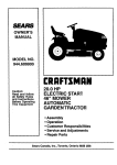
OWNER'S MANUAL
o Assembly
®Operation
• Customer Responsibilities
®Service and Adjustments
• Repair Parts
CAUTION:
Read and follow all safety
rules and instructions
before operating
this equipment.
FOR CONSUMER ASSISTANCE HOT LINE, CALL,THIS TOLL FREE NUMBER: 1-800-659-5917
...............................................................
III
IMIIIIII
IIIIII
ii
SAFETY
RULES
Practices for Ride-On
Safe Operation
Mowers
IMPORTANT:
THiS CUTTING MACHINE IS CAPABLE OF AMPUTATING HANDS AND FEET AND THROWING OBJECTS+
FAILURE TO OBSERVE THE FOLLOWING SAFETY INSTRUCTIONS COULD RESULT IN SERIOUS INJURY OR DEATH+
I,
GENERAL
•
Read, understand, and follow all instructions in the manual
and on the machine before starting.
..........
Only allow responsible adults, who are familiar with the
instructions, to operate the machine.
Clear the area of objects such as rocks, toys, wire, etc.,
which could be picked up and thrown by the blade+
Be sure the areais clear ofother people before mowing. Stop
machine if anyone enters the area.
Never carry passengers+
Do not mow in reverse unless absolutely necessary. Always
look down and behind before and while backing+
Be aware of the mower discharge direction and do not point
it at anyone+ Do not operate the mower without either the
entire grass catcher or the guard in place+
Slow down before turning,
•
o
°
•
=
,,
•
°
°
°
.
°
=
=
II.
OPERATION
Never leave a running machine unattended. Always turn off
blades, set parking brake, stop engine, and remove keys
before dismounting,
Tum off blades when not mowing+
Stop engine before removing grass catcher or'unclogging
chute=
Mow only in daylight or good artificial light,
Do not operate the machine while under the influence of
alcohol or drugs+
Watch for traffic when operating near or crossing roadways.
Use extra care when loading or unloading the machine into
a trailer or truck+
SLOPE
°
°
°
°
°
Watch for holes, ruts, or bumps. Uneven terrain could
ovedum the machine. Taft grass can hide obstacles+
Use slow speed+ Choose a low gear'so that youwill not have
to stop or shift while on the slope,
Follow the manufacturer's recommendations for wheel
weights or counterweights to improve stability+
Use extra care with grass catchers or other attachments+
These can change the stability of the machine,
makeKeepallm°vement°ntheslopessl°wandgraduaLsudden
changes in speed or direction.
Donot
Avoid starting or stopping on a slope. If tires lose traction,
disengage the blades and proceed slowly straightdown the
slope.
DO NOT:
°
Donot turnon slopes unlessnecessary, and then, turnslowly
and gradually downhill, tf possible,
•
Do not mow near drop+offs,ditches, or embankments. The
mower could suddenly tum over tfa wheel is over the edge
of a cliffor ditch, or if an edge caves in.
•
Do not mow on wet grass+ Reduced traction could cause
sliding+
°
Do not try to stabilize the.machine by putting your foot on the
ground.
°
Do not use grass catcher on steep slopes+
CHILDREN
Tragic accidents can occur if the operator is not alert to the
presence of children+ Children are often attracted to the
machine and the mowing activity.
Never assume that
children will remain where you last saw them.
°
Keep children out of the mowing area and under the watchful
care of another responsible adult.
°
Be alert and turn machine off if children enter the area.
°
Before and when backing, look behind and down for small
children.
,,
•
•
Never carry children. They may fall off and be seriously
injured or interfere with safe machine operation°
Never allow children to operate the machine.
Use extra care when approaching blind comers, shrubs,
trees, or other+objects that may obscure vision+
IV. SERVICE
,,
•
=
OPERATION
Slopes are a major factor related to loss+of-control and
tipover accidents, which can result in severe injury ordeath.
All slopes require extra caution, tf you cannot back up the
slope or if you feel uneasy on it, do not mow it.
DO:
°
Mow up and down slopes, not across.
,,
Remove obstacles such as rocks, tree limbs, etc.
o
III.
°
•
,,
,,
•
•
•
Use extra care in handlinggasoline and other fuels+ They are
flammable and vapors are explosive.
Use only an approved container.
Never remove gas cap or add fuel with the engine
running. Allow engine to cool before refueling+ Do not
smoke+
Never refuel the machine indoors.
Never' store the machine or fuel container inside where
there is an open flame, such as a water heater+
Never run a machine inside a closed area.
Keep nuts and bolts, especially blade attachment bolts, tight
and keep equipment in good condition+
Never tamper with safety devices+ Check their proper'
operation regularly.
Keep machine free of grass, leaves, or other debris build-up.
Clean oil or fuel spillage+ Allow machine to cool before
storing.
Stop and inspect the equipment if you strike an object+
Repair', if necessary, before restarting+
Never make adjustments or repairs with the engine running.
Grass catchercomponents are subject towear; damage, and
deterioration, which could expose moving parts or allow
objects to be thrown. Frequently check components and
replace with manufacturer'srecommended parts, when necessary+
Mower blades are sharp and can cut. Wrap the blade(s) or
wear gloves, and use extra caution when servicing them,
Check brake operation frequently. Adjust and service as
required.
............ i
..........
Look for thls symbol to point out impOrI
tant safety precautions.
It means
_J
! i
CAUTIONIII
BECOME ALERTlll
YOUR
"
" "
SAFETY IS INVOLVED,
...........................
CAUTION: Always disconnect spark plug
wireand placewirewhereit cannot contact
spark plug In order to prevent accidental
starting when setting up, transporUng,
adjusting or making repairs,
.... wA,.+.G
A
""'"'"'"'"'""'
"
The engine exhaust from this product
con-
chemicals known to the State of California to cause cancer, birth defects, or other
tains
reproductive harm.
..............................................................
I
!
I
I
I
!
i
|
I
PRODUCT SPECiFiCATIONS
CONGRATULATIONS
on your purchase of a Sears
Tractor. It has been designed, engineered and manufactured to give you the best possible dependability and
performance.
Should you experience any problem you cannot easily
remedy, please contact your nearest Sears Authorized
Service Center/Department Department. We have competent, welFtrained technicians and the proper tools to
service or repair this tractor°
Please read and retain this manual. The instructions will
enable you to assemble and maintain your tractor properly.
Always observe the "SAFETY RULES",
MODEL
NUMBER
HORSEPOWER:
25,0
GASOLINE CAPACITY
AND TYPE:
3.5 GALLONS
UNLEADED REGULAR
OIL TYPE (API-SF/SG!SH):
SAE low30 (above 32°F)
SAE 5W-30 (below 32°F)
OIL CAPACITY:
W/FILTER:
42 PINTS
WIO FILTER: 3..7 PINTS
SPARK PLUG:
'(GAP: ,030")
917_258920
SERIAL
NUMBER
CHAMPION RC12YC
VALVE CLEARANCE:
NOT ADJUSTABLE
GROUND SPEED (MPH):
FORWARD:
REVERSE:
TIRE PRESSURE:
FRONT:
REAR:
CHARGING SYSTEM:
15 AMPS @ 3600 RPM
BATTERY:
AMP/HR:
MIN, CCA:
CASE SIZE:
BLADE BOLT TORQUE:
30-35 FT,LBS.
DATE OF PURCHASE
THE MODELAND SERIAL NUMBERSWlLL BE FOUND
ON A PLATE UNDER THE SEAT.
YOU SHOULD RECORD BOTH SERIAL NUMBER AND
DATE OF PURCHASE AND KEEP IN A SAFE PLACE
FOR FUTURE REFERENCE.
MAINTENANCE
RESPONSIBILITIES
-
Read and observe the safety rules.
°
Fo!lowa regularschedulein maintaining, caringforand
using your tractor.
Followthe tnstnJctions under "Customer Responsibilities" and "Storage" sections of this owner's manual
°
14 PSI
10 PSI
35
280
UIR
WARNING: This tractor is equipped with an internal
combustion engine and should not be used on or near any
unimproved forest-covered, brush-covered or grass-covered land unless the engine's exhaust system is equipped
with a spark arrester meeting applicable local or state laws
(if any). If a spark arrester is used, it should be maintained
in effective working order by the operator°
AGREEMENT
A Sears Maintenance Agreement is available on th_s product. Contact your nearest Sears store for details.
CUSTOMER
0-5.8
0-2.1
In the state of California the above is required by law
(Section 4442 of the California Public Resources Code).
Other states may have similar laws. Federal laws apply on
federal lands. A spark arrester for the muffler ts available
through your nearest Sears Authorized Service Center/
Department (See REPAIR PARTS section of this manual).
LIMITED TWO YEAR WARRANTY ON CRAFTSMAN RIDING EQUIPMENT
For two (2) years from the date of purchase, if this Craftsman Riding Equipment is maintained, lubricated and tuned up according
to the instructionsin the owner's manual, Sears witt repair or replace, free of charge, any parts found to be defective in mater_al
or workmanship°
This Warranty does not cover:
•
,
°
Expendable items which become wom during normal use, such as blades, spark plugs, air cleaners, befts, etco
Tire replacement or repair caused by punctures from outside objects, such as nails, thorns, stumps, or glass°
Repairs necessary because of operator abuse, negligence, Improper storage or accident or the failure to maintain the
equipment according to the instructions contained in the owner's manual..
Riding equipment used for commercial or rental purposes.
LIMITED 90 DAY WARRANTY ON BATTERY
For ninety (90) days from date of purchase, if any battery included with this riding equipment proves defective in material or
workmanship and our testing determines the battery will not hold a charge, Seam will replace the battery at no charge,.
IN-HOME WARRANTY SERVICE ON YOUR CRAFTSMAN RIDING EQUIPMENT IS AVAILABLE AT NO-CHARGE FOR 30
DAYS FROM THE DATE OF PURCHASE. PLEASE CONTACT YOUR NEAREST SERVICE CENTER. AFTER 30 DAYS
FROM THE DATE OF PURCHASE, VVARRANTY SERVICE IS AVAILABLE BY TAKING YOUR CRAFTSMAN RIDING EQUIPMENT TO YOUR NEAREST SEARS SERVICE CENTER. (IN*HOME WARRANTY SERVICE WILL STILL BE AVAILABLE
AFTER 30 DAYS FROM THE DATE OF PURCHASE BUT A STANDARD TRIP CHARGE WILL APPLY.) THIS WARRANTY
APPLIES ONLY WHILE THIS PRODUCT IS IN THE UNITED STATES°
ThisWarrantygives you specificlegal rights,and you mayalsohaveotherrightswhichmay vary from statetostate.
SEARS, ROEBUCK
AND CO., D/817 WA, HOFFMAN
..................................
, ..........................
3
ESTATES,
IL 60I79
iiilllllll
R
............
....................
i
TABLE OF CONTENTS
rlUili'l'lillH[[rr[[[l'["'["'
SAFETY RULES ............................................................ 2
PRODUCT SPECIFICATIONS ...................................... 3
CUSTOMER RESPONSIBILITIES ..................... 3, 16-19
WARRANTY .............................................. .:...... ...... . .... 3
ASSEMBLY ........... ,.................................................. 7-10
OPERATION ...... ..................................................... 11-16
MAINTENANCE SCHEDULE ............. ;........................ 17
'
'[
[
[
I
SERVICE AND ADJUSTMENTS ............................ 21-27
STORAGE ................................................................... 28
TROUBLESHOOTING ............................................ 29-30
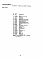
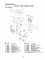
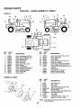
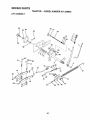
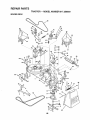
REPAIR PARTS - TRACTOR ................................. 32,,50
REPAIR PARTS - ENGINE .................................... 51-58
PARTS ORDERING/SERViCE ................ BACK COVER
4
,,I,,,I,L_II
ill,,lll,,,ll,,_l,L_II_I
,
i
SERVICE NOTES
' '
,11111,11
II
,11,1,11,
i
I
I
I
/_
i
....I"
I" ,'
,1111
' '1....
I
,i
iii
CO
OF HARDWARE PACK
ii iiii
uJ
.........................
Parts Bag contents
(4) Washers 3/8 x 3/4 x 14 Ga,
_,
(4) Reta,ir}erSpn.'ngs
(12) Carriage Bolts
5/16-18 x 5/8
(4) Clevis Pins
(4) Adjusting Bar
(4) Wheels
(4) Locknut 3/8-16
(12) Crownlock Nuts 3/16 x 8
(1) Shoulder'Bolt
5/t6-18
Seat
Steering
Wheel
(1) Knob
Steering
f
Sleeve
f
-_
!
!
t
I
!
I
!
t
Nose
Roller
e
Video
Cassette
Manual
t
Parts Bag
Parts bag contents not shown full size
III
IUI!I
(1) Washer 17/32 x 1-3/16 x 12 Gauge
_'\,
_r(
_ 1
_(2)
(3) Retainer'Spdngs
(doubleloop)
Front Link Assemblies
Nose Roller
(2) Keys
(4) Retainer Springs "-_'-JA¥
(single loop) I
_/!
Brackets
(2) Nylon Locknuts 3/8-16
Wheel
teering
Insert
_
(2) Hex Bolts
3/8-t6 x 1
Slope Sheet
(2) Washers
17/32 x 7/8 x 16 Ga.
6
LI
LJ
E
LY
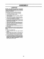
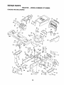
Your newtractor has been assembled atthe factorywith the exception of those parts left unassembled for shipping purposes°
To ensure safe and proper operation of your tractor all parts and hardware you assemble must be tightened securely. Use
the correct tools as necessary to insure proper tightness.
TOOLS REQUIRED FOR ASSEMBLY
A socket wrench setwill make assemblyeasier_ Standard
wrench sizes are listed.
(1) 5/16" wrench
(1) 1/2" wrench
Tire pressure gauge
(2) 9116" wrenches
Utility knife
(1) 3/4" socket with drive ratchet
When right or left hand is mentioned in this manual, it
means when you are in the operating position (seated
behind the steering wheel).
TO REMOVE TRACTOR FROM CARTON
UNPACK CARTON
•
=
•
STEERING
SLEEVE
Remove all accessible loose parts and parts cartons
from carton (See page 6).
Cut, from top to bottom, along lines on all four corners
of carton, and lay panels flat,
Check for any additional loose parts or cartons and
remove.
!
!
/
!
i
II
!
FIG. 1
BEFORE
ROLLING TRACTOR
ATTACH STEERING
OFF SKID
WHEEL (See Fig. 1)
o
Remove hex bolt, lock washer and large flat washer
from steering shaft.
°
Positionfront wheels of the tractorso they are pointing
straight forward.
° Slide steering sleeve over steering shaft.
,
Position steering wheel so cross bars are horizontal
(left to right) andslide onto steering wheel adapter.
° Secure steering wheel to steering shaft with hex bolt,
Iockwasher and large flat washer previously removed°
Tighten securely.
° Snap steering wheel insert into center of steering
wheel.
•
Remove protective materials from tractor hood and
grill.
IMPORTANT: CHECK FOR AND REMOVE ANY STAPLES
IN SKIDTHAT MAY PUNCTURE T1RES WHERE TRACTOR
IS TO ROLL. OFF SKID.
HOW TO SET UP YOUR TRACTOR
CHECK BATTERY (See Fig. 2)
°
Lift hood to raised position.
•
tf this battery is put into service after month and year
indicated on label (label located between terminals)
charge battery for minimum of one hour at 6-10 amps,
(See BATTERY" in MAINTENANCE section of this
manual for charging instructions).
LABEL
TO ROLL TRACTOR OFF SKID (See Operation
section for location and function of controls)
°
•
°
•
°
°
Press liftlever plunger and raise attachment liftlever to
its highest position.
Release parking brake by depressing clutch/brake
pedal.
Place freewheel control in freewheeling position to
disengage transmission (See "TO TRANSPORT" in
the Operation section of this manual).
Roll tractor forward off skid.
Remove mower and packing materials,
Remove ties from V-belts.
FIG. 2
•
INSTALL SEAT (See Fig. 3)
Adjust seat before tightening adjustment knob_
Remove cardboard packing on seat pan.
,
°
Place seat on seat pan and assemble shouider bolt.
o Assemble adjustment knob and flat washer loosely.
Do not tighten.
o Tighten shoulder bolt securely.
•
Lower seat into operating position and sit on seat.
°
Slide seat until a comfortable position is reached which
allows you to press clutch/brake pedal all the way
down.
= Get off seat without moving its adjusted position,
Raise seat and tighten adjustment knob securely.
=
Adjust gauge wheels to highest position for ease of
mower deck assembly,
Adjust gaugewheels before operating mower asshown
in the operation section of this manual.
GAUGE
WHEEL
BRACKET
SHOULDER
BOLT
SEAT
ADJUSRNG
BAR
GAUGE
WHEEL
3/8 WASHER
CARRIAGE
BOLTS
3/_16CENTER
LOCKNUT
FIG. 4
ADJUSTMENT
KNOB
FIG. 3
TO ATTACH NOSE ROLLER (See Fig. 5)
°
Positionbrackets. 17/32x7/Sx 16 gauge washers, and
nose rollerbetween deck mounting brackets as shown.
Be sure to positionbrackets on correct side, as shown°
,
Install 3/8.16 x 1 hex bolts and 3/8-16 lock nuts as
shown. Tighten hardware securefy,
NOTE: Be sure bracket tabs are positionedin tab holes in
deck brackets.
CHECK TIRE PRESSURE
The tires on your tractorwere overinflated at the factory for
shippingpurposes. Correct tire pressure is important for
best cutting performance.
.
Reduce tire pressure to PSI shown in "PRODUCT
SPECIFICATIONS" on page 3 of this manual.
CHECK BRAKE SYSTEM
"B" BRACKET TAB
TAB
After you learn how to operate your tractor, check to see
that the brake is properly adjusted, See "TO ADJUST
BRAKE" in the Service and Adjustments section of this
manual.
NOSE ROLLER
ASSEMBLE GAUGE WHEELS AND BRACKETS TO MOWER DECK (See Fig. 4)
HEX
The gauge wheels are designed to keep the mower deckin
proper position when operating mower. Be sure they are
properlyadjusted to ensure optimummower performanceo_
° Attach front gauge wheel brackets marked front left
(FL), front right (FR) to mowerdeck using (3) carriage
bolts and (3) locknuts. For ease of installationdo not
tighten locknuts until all carriage bolts have been
installed.
•
Attach rear gauge wheel brackets marked rear left (R
L), rear right (RR) to mower deck using (3) carriage
bolts and (3) Iocknuts. For ease of installationdo not
tighten Iocknuts until all carriage bolts have been
installed.
° Slide gauge wheel bar down into bracket channel, Be
sure that gauge wheel bar aligning holes are on top,
Assemble gauge wheels as shown using shoulder
bolts, 3/8 washers and 3/8-16 center Iocknuts and
tighten securely.
"A"
BRACKET
LOCK NUT'
TAB
WASHER
FIG. 5
8
INSTALL MOWER AND DRIVE BELT
(See Figs. 5A and 7)
Place the suspension arms on inward pointing deck
pins° tf necessary, rock and raise front of mower to
align deck pins with the holes in suspension arms.
Retain with double loop retainer springs with loops
down as shown°
Be sure tractor is on level surface and mowersuspension
arms are raised with attachment lift control, Engage parking brake.
•
o
Cut and remove ties securinganti-sway bar and belts,
Swing anti-sway bar to left side of mower deck,
=
°
Slide mower undertractorwith dischargeguardto right
side of tractor°
IMPORTANT: CHECK BELT FOR PROPER ROUTING IN
ALL MOWER PULLEY GROOVES. INSTALL BELT INTO
ELECTRIC CLUTCH PULLEY GROOVE,
°
Install one front linkin top hole of the L.H, front mower
bracket and L.H. front suspensionbracket. Retain with
two single loop retainer springs as shown,
°
installsecond front linkin R.H_front suspensionbracket
only and retain with single loop retainer spring as
shown,
°
Slide right side of mowerback and install link in top hole
of R.H. front mower bracket, Retain with single loop
retainer spring as shown,
°
Turn height adjustment knob counterclockwiseuntil it
stops.
°
Lower mower linkage with attachment lift control.
DOUBLE LOOP
RETAINER
SPRING (Inward
pointingdock plns}
•
°
Connect anti-sway bar to chassis bracket under left
footrest and retain with double loop retainer spring.
Turn height adjustment knob clockwise to remove
slack from mower suspension.
Raise deck to highest position.
Adjust gauge wheels before operating moweras shown
in the Operation section of this manual.
CHECK MOWER LEVELNESS
For best cuttingresults, mower should be properly leveled.
See "TO LEVEL MOWER HOUSING" in the Service and
Adjustments section of this manual.
CHECK
BELTS
FOR PROPER
POSITION
OF ALL
See the figures thatare shown for replacing motion, mower
drive, and mower blade drive belts in the Service and
Adjustments section of this manual. Verify that the belts are
routed correctly.
FRONT
SUSPENSION
BRACKETS
SUSPENSION
ARMS
FRONT
MOWER
BRACKET
FRONT
LINK
ELECTRIC
CLUTCH
PULLEY
CHASSIS
SINGLE LOOP
RETAINER
SPRINGS
GAUGE
WHEEL
/
ANTI-SWAY
BAR
/
DOUBLE
LOOP
RETAINER
SPRING
DISCHARGE
GUARD
IDLER PULLEY
FIG. 5A
9
_.,,,
,,ill iil,,i
i ,,,,,lll,,lllllll,,ll,,,i
,i , i
J CHECKLIST
BEFORE YOU OPERATE AND ENJOY YOUR NEW
TRACTOR, WE WlSH TO ASSURE THAT YOU RECEIVE
THE BEST PERFORMANCE AND SA TISFAC TION FROM
THIS QUALITY PRODUCT.
PLEASE REVtEW THE FOLLOWING CHECKLIST."
v'
•f
All assembly instructions have been completed.
No remaining loose parts in carton.
/
Battery is properly prepared and charged.
1 hour at 6 amps).
/
Seat is adjusted comfortably and tightened securely.
/
All tires are properly inflated. (For shipping purposes,
the tires were ovednflated at the factory).
,/
Be sure mower deck is properly leveled side-to-side!
front-to-rear for best cutting results. (Tires must be
properly inflated for leveling).
(Minimum
,!
Check mower and drive belts. Be sure they are routed
properly around pulleys and inside all belt keepers.
,# Check wiring. See that all connections are still secure
and wires are properly clamped.
/
Before driving tractor, be sure freewheel control is in
drive position°
WHILE LEARNING HOW TO USE YOUR TRACTOR, PAY
EXTRA ATTENTION TO THE FOLLOWING IMPORTANT
ITEMS:
,t"
Engine oil is at proper level.
/
Fuel tank is filled with fresh, clean, regular unleaded
gasoline.
,t" Become familiar with all controls - their location and
function. Operate them before you start the engine°
,/ Be sure brake system is in safe operating condition°
,/
It is important to purge the transmission before operating your tractor for the firsttime. Follow proper starting
and transmission purging instructions (See,_O START
ENGINE and PURGE TRANSMISSION in the Operation section of this manual)°
10
,
i ,,
,
OPE
These symbols may appear on your tractor or in literature supplied with the product. Learn and understand their meaning,
BATTERY
CAUTION OR
WARNING
REVERSE
FORWARD
FAST
SLOW
ENGINE ON
ENGINE OFF
OIL PRESSURE
CLUTCH
LIGHTS ON
OVER TEMP
LIGHT
0 0
FUEL
CHOKE
MOWER HEIGHT
DIFFERENTIAL
LOCK
"k
1
PARKING BRAKE
LOCKED
UNLOCKED
L
REVERSE
NEUTRAL
HIGH
LOW
PARKING BRAKE
MOWER LIFT
ATTACHMENT
CLUTCH ENGAGED
ATTACHMENT
CLUTCH DISENGAGED
KEEP AREA CLEAR
SLOPE HAZARDS
(SEE SAFETY RULES SECTION)
IGNITION
DANGER, KEEP HANDS AND FEET AWAY
11
FREE WHEEL
(Automatic Models only)
.........
,,,,,,,11
ii iiii
,,,i
'"M '"'1II1'
IIIII1'
IIII
.................
IIII1'""11
I'111"111" '1'"'1 I I ........................
OPERATION
......................
i'1 'IM"
i,, iii,
,,
I'
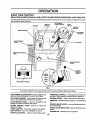
KNOW YOUR TRACTOR
READ THIS OWNER'S
MANUAL AND SAFETY RULES BEFORE OPERATING
YOUR TRACTOR,
Compare the illustrationswith your tractorto famlliariz_yourself withthe locationof various controlsand adjustments° Save
this manual for future reference.
ATTACHMENT
CLUTCH SWITCH
THROTTLE
CONTROL
AMMETER
" *
UGHT
SWITCH
IGNITION
SWITCH
_"
CHOKE CONTROL
LIFT LEVER
PLUNGER
CLUTCH/BRAKE
PEDAL
HOUR
METER
LIFT LEVER
HEIGHTADJUSTMENT
KNOB
PARKING BRAKE
LEVER
MOTION
CONTROL
LEVER
SPEEDS:
3
2
FREEWHEEL
CONTROL
FIG. 6
Our tractors conform to the safety standards of the American National Standards Institute,
ATrACHMENTCLUTCH SWITCH- Usedto engagemower
blades or other attachments mounted to your tractor,
LIFT LEVER PLUNGER - Used to raise and lower mower
deck or other attachments mounted to your tractor.
FREEWHEEL CONTROL - Disengages transmission for
pushing or slowly towing the tractor with the engine off.
IGNITION SWITCH - Used to start and stop the engine,
AMMETER - indicates battery charging (÷) or discharging
(-).
CLUTCH/BRAKE PEDAL - Used for declutching and
brakingthe tractor and starting the engine°
MOTION CONTROL
direction of tractor.
PARKING BRAKE LEVER - Locks clutctdbrakepedal into
the brake position.
LEVER - Selects the speed and
HEIGHTADJUSTMENT
height.
CHOKE CONTROL - Used when starting a cold engine.
LIGHT SWITCH - Turns the headlights on and off.
THROTTLE CONTROL - Used to control engine speed.
KNOB- Used to adjust the mower
HOURMETER - indicates hours of operation,
12
OPEFIATI
i
,,_ ,.........
..................
_,!
The operation of anytractor can result in foreign objects thrown into the eyes, which can result
in severe eye damage. Always wear safety glasses or eye shields while operating your tractor
or performing any adjustments _or repairs. We recommend a wide vision safety mask over
_z-_
........
spectacles or standard safety glasses.
HOW TO USE YOUR TRACTOR
TO SET PARKING
IMPORTANT: LEAVING THE IGNITION SWITCH IN ANY
POSITION OTHER THAN "OFF" WILL CAUSE THE
BATTERY TO BE DISCHARGED, (DEAD).
NOTE: Under certain conditionswhen tractor is standing
idle withthe engine running, hot engine exhaust gases may
cause "browning" of grass. To eliminate this possibility,
always stop engine when stopping tractor on grass areas.
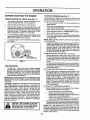
BRAKE (See Fig. 7)
Your tractor is equipped with an operatorpresence sensing
switch. When engine is running, any attempt by the
operator to leave the seat without first setting the parking
brake will shut off the engine.
•
Depress clutch/brake pedal intofull "BRAKE" position
and hold.
•
Place parkingbrake lever in"ENGAGED" positionand
release pressurefrom clutch/brakepedalr Pedalshould
remain in BRAKE" position. Make sure parkingbrake
will hold tractor secure.
THROTTLE
PUSH IN TO
ATTACHMENT CLUTCH
"DISENGAGE"
SWITCH PULL OUT TO
CONTROL LEVER
_
..................................._.;:....,, ,
I
,_
i ,tlA,
| _
!.........
.,
"ENGAGE'I.
TO USE CHOKE CONTROL
I
(SEE FIG, 7)
(See Fig. 7)
Use choke controlwheneveryou are starting a cold engine_
Do not use to start a warm engine.
° To engage choke control, pull knob out° Slowly push
knob in to disengage°
,..--_._
ADJUSTMENT
KNOB
_\
TO MOVE FORWARD AND BACKWARD
(See Fig. 7)
The directionand speedof movementiscontrolledby the
motioncontrollever,
CONTROL
\.<;v:L.o
,
BRAKE
"ENGAGED"
POSITION
°
Start tractor with motion control lever in neutral (N)
position,
Release parking brake and clutcWbrake pedal.
°
Slowly move motion control lever to desired position,
"DISENGAGED"
POSITION
FIG. 7
STOPPING
CONTROL
I
i
!
Always operate engine at full throttle.
°
Operating engine at less than full throttle reduces the
battery charging rate.
,
Full throttle offers the best mower performance.
CLUTC "H_'RAKE_"_
/I
CAUTION: Always stop tractor com.
pletely, asdescribedabove, beforeleavmg the operator's position; to empty
....gras,s
........catcher, etc.
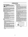
TO USE THROTTLE
C =oL
'\
"DRIVE"
POSITION
,,ill,i,
TO ADJUST
(See Fig. 7)
CUTTING
HEIGHT
The cuttingheight is controlledby turningthe height adjustment knob in desired direction.
° Turn knob clockwise ((_) to raise cutting heighto
° Turn knob counterclockwise (P'_) to lower cutting
height,
The cutting height range is approximately 1_112"to 4-1/2",
The heights are measured from the ground to the blade tip
with the engine not running. These heights are approximate and may vary depending upon soil conditions, height
of grass and types of grass being mowed_
•
The average lawn should be cut to approximately 2-1/2
inches during the cool season and to over 3 inches
during hot months. For healthier and better looking
lawns, mow often and after moderate growth.
For best cutting performance, grass over 6 inches in
height should be mowed twice. Make the first cut
relatively high; the second to desired height.
MOWER BLADES• To stop mower blades,move attachment clutch switch
to "DISENGAGED" position.
GROUND DRIVE To stop ground drive, depress clutch/brake pedal into
full BRAKE position°.
•
Move motion control lever to neutral (N) position.
IMPORTANT: THE MOTION CONTROL LEVER DOES
NOT RETURN TO NEUTRAL (N) POSITION WHEN THE
CLUTCHIBRAKE PEDAL IS DEPRESSED.
ENGINE °
Move throttle control to slow position.
NOTE: Failure to move throttlecontrolto slow positionand
allowing engine to idle before stopping may cause engine
to "backfire'L
•
Turn ignition key to "OFF" position and remove key.
Always remove key when leaving tractor to prevent
unauthorized use.
°
Never use choke to stop engine.
MOWER
(See Fig. 7)
°
13
,III,!,,,!,tulIIII,/,!UI ,
,
I
,,,
II
IIIII
OP
,,,,,,,,,,,,, ,,, ,,,,,,,,,
TO ADJUST
GAUGE WHEELS
i........................
!
Gauge wheels are properly adjustedwhen they are slightly
off the ground when mower is at the desired cutting height
in operating position. Gauge wheels then keep the deck in
proper position to help prevent scalping in most terrain
conditions.
e
,,
TO OPERATE ON HILLS
(see Fig. 8)
CAUTION: Do not drive up or down
hills with slopes greater than 15 ° and
do not drive across any slope.
•
Choose the slowest speed before starting up or down
hills.
• Avoid stopping or changing speed on hills.
°
If slowing is necessary, move throttle control lever to
slower position.
°
If stopping is absolutely necessary, pustl clutch/brake
pedal quickly to brake position and engage parking
brake.
° Move motion control lever to neutral (N) position.
IMPORTANT: THE MOTION CONTROL LEVER DOES
NOT RETURN TO NEUTRAL (N) POSITION WHEN THE
CLUTCHIBRAKE PEDAL IS DEPRESSED.
° To restart movement, slowly release parking brake and
clutch/brake pedal.
o Slowly move motion control lever to slowest setting.
° Make all turns slowly.
Be sure tractor is on a flat level surface.
•
Lower' mower and adjust mower to desired cutting
height.
°
Remove retainer spring and clevis pin which secure
each gauge wheel bar.
°
Lower gauge wheels to ground. Raise gauge wheels
slightly to align holes in bracket and gauge wheel bar
and insert clevis pin. Gauge wheels should be slightly
off the ground.
° Replace retainer' spring Into clevis pin.
IMPORTANT: BE SURETO READJUST GAUGE WHEELS
IF YOU CHANGETHE CUTTING HEIGHT OFTHE MOWER
3ECK.
RETAINER
SPRING
TO TRANSPORT
(See Figs. 6 and 10)
When pushingor towingyour tractor, be sure to disengage
transmission by placing freewheel control in freewheeling
position. Free wheel control is located at the rear drawbar
of tractor.
CLEVIS
PiN
FIG. 8
TO OPERATE
MOWER (See Figs. 6 and 7)
°
Raise attachment lift to highest position with attachment lift control.
.
,,
Remove retainer spring from freewheel control rod.
Push control rod in to disengage transmission and
reinsert retainer spring into control rod hole now on
back side of the bracket.
.
Do not push or tow tractor at more than two (2) MPH.
.
To reengage transmission, reverse above procedure.
NOTE: To protect hood from damage when transporting
your tractor on atruckor a trailer, be sure hood is closed and
secured to tractor. Use an appropriate means of tying hood
to tractor (rope, cord, etc.).
Your tractor is equipped with an operator presence sensing switch. Any attempt by the operator to leave the seat
withthe engine runningand the attachment clutchengaged
will shut off the engine.
* Select desired tleight of cuL
o Lower mower with attachment lift control.
,
Start mower blades by engaging attachment clutch
control.
, TO STOP MOWER BLADES - disengage attachment
clutchcontrol.
without either the entire grass catcher,
CAUTION:
operate or
thethe
mower
on
mowers Do
so not
equipped,
discharge guard in place.
,_R.H,
RUNNER
DISCHARGE
GUARD
FIG. 10
FIG. 9
14
BEFORE STARTING THE ENGINE
TO START ENGINE (See Fig. 7)
When starting the engine for the first time or if the engine
has runout of fuel, it will take extra cranking time to move
fuel from the tank to the engine°
° Be sure freewheel control is in the transmission engaged position.
CHECK ENGINE OIL LEVEL (See Fig. 11)
o
°
°
,
o
The engine in your tractor has been shipped, from the
factory, already filled with summer weight oil.
Check engine oil with tractor on level ground.
Unthread and remove oil fill cap/dipstick; wipe oil off°
Reinsertthe dipstickintothe tube and restoilfill cap on
the tube. Do not thread the cap ontothe tube. Remove
and read oil level. If necessary, add oil until "FULL"
mark on dipstick is reached. Do not overfill.
For cold weather operation you should change oil for
easier starting (See "OIL VISCOSITY CHART" in the
Maintenance section of this manual).
To change engine oil, see the Maintenance section in
this manual.
FIG. 11
ADD GASOLINE
°
Fill fuel tank. Use fresh, clean, regular unleaded
gasoline with a minimum of 87 octane° (Use of leaded
gasoline will increase carbon and lead oxide deposits
and reduce valve life)o Do not mix oil with gasoline.
Purchase fuel in quantities that can be used within 30
days to assure fuel freshness,
IMPORTANT: WHEN OPERATING IN TEMPERATURES
BELOW 32°F(0°C), USE FRESH, CLEAN WINTER GRADE
GASOLINE TO HELP INSURE GOOD COLD WEATHER
STARTING°
COLD WEATHER STARTING (50 ° F and below)
° When engine starts, slowly push choke control in until
the engine begins to run smoothly. Continue to push
the choke control in small steps allowing the engine to
accept small changes in speed and toad, until the
choke control is fully in. If the engine starts to run
roughly, pull the choke control out slightly for a few
seconds and then continue to push the control in
slowly. This may require an engine warm-up period
from several seconds to several minutes, depending
on the temperature.
AUTOMATIC TRANSMISSION WARM UP
WARNING: Experience indicates that alcohol blended
fuels (called gasohol or using ethanol or methanol) can
attract moisture which leads to separation and formation of
acids during storage. Acidic gas can damage the fuel
system of an engine while in storage. To avoid engine
problems, the fuel system should be emptied before storage of 30 days or longer. Drain the gas tank, start the
engine and let it run until the fuel lines and carburetor are
empty. Use fresh fuel next season. See Storage instructions for additional information. Never use engine or
carburetor cleaner products in the fuel tank or permanent
damage may occur.
_
i,iii
ii
°
,i,,llllllii
filler neck. Do not overfill. Wipe off any
spilled
CAUTION:
oil orFill
fuel.to Do
bottom
not store,
of gas
spill
tank
or
use gasoline near an open flame.
=
,
=
=
Sit on seat in operating position,depress clutch/brake
pedal and set parking brake.
Place motion control lever in neutral (N) position.
Move attachment clutch to "DISENGAGED" position.
Move throttlecontrol to fast position
Pull choke control out for a cold engine start attempt.
For a warm engine start attempt the choke controlmay
not be needed.
NOTE: Before starting, read the warm and cold starting
procedures below.
° Insertkeyintoignition and turnkeyclockwiseto"START"
positionand release key as soo'nas engine starts° Do
not run starter continuouslyfor more than fifteen seconds per minute. If the engine does not start after
several attempts, push choke control in, wait a few
minutesand try again, tf engine stilldoes not start, pull
the choke control out and retry.
WARM WEATHER STARTING (50 ° F and above)
° When engine starts, slowly push choke control in until
the engine begins to run smoothly. If the engine starts
to run roughly,pull the choke control out slightly for a
few seconds and then continue to push the control in
slowly.
•
The attachments and ground drive can now be used. If
the engine does not accept the load, restart the engine
and allowit to warm up for one minute using the choke
as described above.
FILL CAP/DIPSTICK
...............................
°
J
/
15
Before driving the unit in cold weather, the transmission should be warmed up as follows:
° Be sure the tractor is on level ground°
o Place the motion control lever in neutral.
Release the parkingbrake and let the clutch/brake
slowly return to operating position.
• Allow one minute for transmissionto warm up.This
can be done during the engine warm up period.
° The attachments can be used duringthe engine warmup period after the transmission has been warmed up
and may requirethechoke controlbe pulledout slightly.
NOTE: If at a high altitude (above 3000 feet) or in cold
temperatures (below 32 F) the carburetor fuel mixture may
need to be adjusted for best engine performance. See %0
ADJUST CARBURETOR" in the Service and Adjustments
section of this manual.
..................................
T_,,,
OPERATION
..,_.,i
.
I
i
iI i I
..............................................
o
°
To ensure proper operation and performance, it is recommended that the transmission be purged before operating
tractor for the first time_ This procedure will remove any
trapped air inside the transmission which may have developed during shippingof your tractor,
IMPORTANT: SHOULD YOUR TRANSMISSION REQUIRE
REMOVAL FOR SERVICE OR REPLACEMENT, IT
SHOULD BE PURGED AFTER REINSTALLATION
BEFORE OPERATING THE TRACTOR,
•
=
Place tractorsafely on level surface with engine off and
parking brake set.
°
o
Disengage transmission by placing freewheel control
in freewheeling position (See "TO TRANSPORT" in
this section of manual).
°
Sittinginthetractorseat, startengineo Aftertheeng!ne
is running, move throttle control to slow position. With
motion control lever in neutral (N) position, slowly
disengage clutch/brake pedal.
=
Move motion control lever'to full forward position and
hold for five (5) seconds. Move lever to full reverse
position and hold for five (5) seconds. Repeat this
procedure three (3) times.
°
°
°
°
°
NOTE; During this procedure there will be no movementof
drive wheels. The air is being removed from hydraulic ddve
system.
° Move motion control leverto neutral (N) position. Shutoff engine and set parking brake.
Engage transmission by placing freewheel control in
driving position (See"TOTRANSPORT" in this section
of manual).
=
Sitting in thetractor seat, start engine. Afterthe engine
is running, move throttle contro/to half (1/2) speed.
With motion control lever in neutral (N) position, slowly
disengage clutch/brake pedal.
•
Slowly move motion control lever forward, after the
tractormoves approximatelyfive (5) feet, slowlymove
motion control lever to reverse position. After the
tractor moves approximately five (5) feet return the
motioncontrollever tothe neutral (N) position. Repeat
this procedure with the motion control lever three (3)
times,
•
II
ill I
i I
MOWING TIPS
PURGE TRANSMISSION
°
Illllllllllllll
°
Tire chains cannot be used when the mower housing
is attached to tractor,
Mower should be properly leveled for best mowing
performance, See'q'O LEVEL MOWER HOUSING" in
the Service and Adjustments section of this manual,
Use the runner on the right hand side of mower as a
tghuide,The blade cuts approximately an inch outside
e runner (See Fig, 8),
The left hand side of mower should be used for trimming,
Drive so that clippings are discharged onto the area
that has been cut. Have the cut area to the rightof the
tractor, This will result in a more even distributionof
clippingsand more uniformcutting,
When mowing large areas, start by turning to the right
so that clippings will discharge away from shrubs,
fences, driveways, etc_ After' one or two rounds, mow
in the opposite direction mal,Jng left hand turns until
finished (See Fig. 12).
If grass is extremely tall, it should be mowed twice to
reduce load and possible fire hazard from dried clippings. Make first cut relatively high; the second to the
desired height.
Do not mow grass when it is wet. Wet grass will plug
mower and leave undesirable clumps. Allow grass to
dry before mowing.
Always operate engine at full throttle when mowing to
assure better mowing performance and proper discharge of material Regulate ground speed by selecting a low enough gear to give the mower cutting
performance as wetl as the quality of cut desired.
When operating attachments, select a ground speed
that will suit the terrain and give best performance of
the attachment being used.
IllL_ Illlll iiii
_ll II _
FIG. 12
Your tractor is now purged and now ready for normal
operation.
16
NE ....
CleanAir
Filler
Clean
_r Screen
.........
V._
inspect MuffterlSpark Arrester
NEC ean
Eo;in;
coo,,
V.
....
....
Replace Spark Ptug
if
' Repiace Air Ft]ler Paper Cadddge
,,,.,,,,i,,
V.
V._
'Relo!_oe Fuel Filler
.........
1_Changemore_enwflenopera_ngunr_eraheavyto_dorlnl_ghambtenHemperaturee.
2 _ Se_]co morn often when operal_ng in ditty or dusty conditions
3 - !! equipped w_ o_l_lter, c_a.__e oil every 50 hours
4 - RelY_,ce ldsdes me_, often when mowing In sandy soil..
i_
.
i"
5 * It equtpped wiLh adjuslab_n system.
6 - Not required if equipped wtlh ma_nlenance-fme
baileR/
7 - Tighten front axle pivot boll to 35 ft.qbe., rnex.hnum,
Do not overgghfen
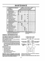
GENERAL RECOMMENDATIONS
The warranty on thistractor does not cover items that have
been subjected to operator abuse or negligence. To
receive full value from the warranty, operator must maintain
tractor as instructed in this manual,
LUBRICATION
CHART
(_)TIE ROD BALL JOINTS
Some adjustments will need to be made periodically to
properiy maintain your tractor.
All adjustments in the Service and Adjustments section of
this manual should be checked at least once each season°
•
Once a year you should replace the spark plug, clean
or replace air filter, and check blades and belts for
wear. A new spark plug and clean air filter assure
proper air-fuel mixture and help your engine run better
and last longer.
o,,°,,oz,,,
(_) STEERING
SECTOR GEAR
TEETH
O0"®
oo,.,,oz,,,
ENGINE _)
BEFORE EACH USE
,
•
•
•
,
Check engine oll level,
Check brake operation°
Check tire pressure_
Check operator presence and
intedock systems for proper operation_
Check for loose fasteners.
IMPORTANT."
DO NOT OIL OR GREASE THE PIVOT POINTS
WHICH HAVE SPECIAL NYLON BEARINGS., VISCOUS LUBRICANTS WILL ATTRACT DUST AND DIRT THAT WILL SHORTEN
THE LIFE OF THE SELF-LUBRICATING
BEARINGS.
IF YOU
FEEL THEY MUST BE LUBRICATED,
USE ONLY A DRY, POWDERED GRAPHITE TYPE LUBRICANT SPARINGLY,,
(_ SPRAY SILICONE LUBRICANT (MOVE BOOTS TO LUBRICATE)
(_ GENERAL PURPOSE GREASE
(_) REFER TO CUSTOMER RESPONSIBILITIES
17
"ENGINE"
SECTION
IVlAINTENA
ii1,,
ii1,11111_rll
........
...........
II '1 II !1 L
TRACTOR
TRAILING
EDGE UP
Always observe safety rules when performingany maintenance.
MANDREL
ASSEMBLY
BLADE
BRAKE OPERATION
tf tractor requires more than six (6) feet stopping distance
at highspeed in highestgear, then brake mustbe adjusted,
(See "TO ADJUST BRAKE" in the Service and Adjustments section of this manual).
LOCKWASHER_
STAR
TIRES
=
Maintain proper air' pressure in all tires (See "PRODUCT SPECIFICATIONS" on page 3 of this manual).
*A GRADE 8 HEAT TREATED BOLT CAN BE
IDENTIRED BY SIX LINES ON THE BOLT HEAD.
°
Keep tires free of gasoline, oil, or insectcontrolchemicals which can harm rubber_
FIG. 13
°
Avoid stumps, stones deep ruts, sharp objects and
other hazards that may cause t re damage.
TO SHARPEN
BLADE (See Fig. 14)
NOTE: To seal tire punctures and prevent flat tires due to
slow leaks, tire sealant may be purchased from your local
parts dealer° Tire sealant also prevents tire dry rot and
corrosion.
NOTE: We do not recornrnend sharpening blade- but ifyou
do, be sure the blade is balanced.
Care should be taken to keep the blade balanced. An
unbalanced blade willcause excessive vibrationand eventual damage to mower and engine°
OPERATOR
°
PRESENCE
SYSTEM
Be sure operator presence and interlock systems are
working properly. If your tractor does not function as
described, repair' the problem immediately.
°
°
The engine should not start unless the clutch/brake
pedal is fully depressed and attachement clutch control
{s in the disengaged position.
When the engine is running,any attempt by the operator to leave the seat without first setting the parking
brake should shut off the engine.
°
When the engine is running and the attachment clutch
is engaged, any attempt by the operator to leave the
seat should shut off the engine.
,
The attachment ctutchshouldneveroperate unlessthe
operator is in the seat.
The blade can be sharpened with a file or on a grinding
wheel, Do not attempt to sharpen while on the mower,
ancer.)
NOTE: Do not use a nail for balancing blade. The lobes of
the center hole may appear to be centered, but are not.
•
Slide blade on to an unthreaded portion of the steel bolt
or pin and hold the bolt or pin parallel with the ground.
If blade is balanced, it should remain in a horizontal
position. If either end of the blade moves downward,
sharpen the heavy end until the blade is balanced.
BLADE CARE
For best results mower blades must be kept sharp. Replace bent or damaged blades.
BLADE REMOVAL
(See Fig. 13)
•
Raise mower to highest position to allow access to
blades=
,
Remove hex bolt,lockwasherandflatwasher secudng
blade.
FIG. 14
BATTERY
°
Install new or resharpened blade with trailing edge up
towards deck as shown.
IMPORTANT: TO ENSURE PROPER ASSEMBLY,
CENTER HOLE IN BLADE MUST ALIGN WITH STAR ON
MANDREL ASSEMBLY_
o Reassemble hex bolt, lock washer and flat washer in
exact order as shown°
Your tractor has a battery charging system which is sufficient for normal use. However, pedodic charging of the
battery with an automotive charger will extend its life.
° Tighten bolt securely (27-35 Ft. Lbs. torque).
IMPORTANT: BLADE BOLTtS GRADE 8 HEAT TREATED.
18
=
Keep battery and terminals clean_
,,
°
Keep battery bolts tight.
Keep small vent holes open.
•
Recharge at 6-10 amperes for i hour.
.........................
,,,,.
.:.
::
.......... :: ......
;:
.........................
CE
inl,,,i,u,i
ull,
,i,ul_ll_ i,
i, i I
HII'I_I_I"I'I"II' '
.... iii
I I
IIIIH
I
ii
T::
...............
:_,_;
..............
TO CLEAN BATTERY AND TERMINALS
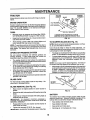
TO CHANGE ENGINE OIL (See Figs. 15 and 16)
Corrosion and dirt on the battery and terminals can cause
the battery to "leak" power,,
°
Remove terminal guard°
Determine temperature range expected before oil change°
All oil must meet API service classification SF, SG or SHo
,
Be sure tractor is on level surface..
°
Disconnect BLACK battery cable first then RED battery cable and remove battery from tractor.
,
°
Oil will drain more'freely when warm°
Catch oil in a suitable container.
•
Rinse the battery with plain water and dryr
°
"
Clean terminals and battery cable ends with wire brush
until bdght,
°
Remove oil fill cap/dipstick,. Be careful not to allow dirt
to enter the engine when changing oil.
Remove drain plugo
•
Coat terminals with grease or petroleum jelly.
•
.
Reinstall battery (See "REPLACING BATTERY" in the
SERVICE AND ADJUSTMENTS section of this
manual).
After oil has drained completely, replace oil drain plug
and tighten securely.
,
Refill engine with oil through oil fill dipstick tube. Pour
slowly. Do not overfill. For approximate capacity see
PRODUCT SPECIFICATIONS
on page 3 of this
manual.
°
Use gauge on oil fill cap/dipstick forchecking level. Be
sure dipstick is in all the way for accurate reading.,
Keep oil at FULL line on dipstick.
TRANSAXLE
COOLING
The fan and cooling fins of transmission should be kept
clean to assure proper cooling°
Do not attempt to clean fan or transmission while engine is
running or while the transmission is hot. To prevent
possible damage to seals, no not use high pressure water
or steam to clean transaxle.
•
Inspect cooling fan to be sure fan blades are intact and
clean.
°
Inspect cooling fins for dirt, grass clippings and other
materials° To prevent damage to seals, do not use
compressed air or high pressure sprayer.
TRANSAXLE
OIL DRAIN
PLUG
AIR SCREEN
PUMP FLUID
ENGINE OIL
FILL CAP/
DIPSTICK
The transaxle was sealed at the factory and fluid maintenance is not required for the fife of the transaxle. Should
the transaxle ever leak or require servicing, contact your
nearest authorized service center/departmento
FIG. 16
V-BELTS
CLEAN
Check V-belts for deterioration and wear after 100 hours of
operation and replace if necessary. The belts are not
adjustable, Replace belts if they begin to slip from wear.
LUBRICATION
Only use high quality detergent oil rated with API service
classification SF, SG, or SH° Select the oil's SAE viscosity
grade according to your expected operating temperature.
SAE VISCOSITY GRADES
.......
-2o_
°c-_o.
O*
30_
-2'o- -1_"
TEMPERATURE
32"
40"
60 *
o".........lo'
RANGE ANTICIPATED
80"
2o.
10(}'
3o'
(See
Fig. 16)
Air screen must be kept free of dirt and chaff to prevent
engine damage from overheating° Clean with a wire brush
or compressed air to remove dirt and stubborn dried gum
fibers,
ENGINE
=F .....
AIR SCREEN
;o"
BEFORE NEXT OIL CHANGE
FIG. 15
Change the oil after every 50 hours of operation or at least
once a year if the tractor is not used for 50 hours inone year,,
Check the crankcase oil level before starting the engine
and after each eight (8) hours of operation. Tighten oil fill
cap/dipstick securely each time you check the oil level,
19
MAINTENANCE
i,JllJlllllll
r' i
CLEAN AIR INTAKF-JCOOLING
AREAS
,,,
"1'1'1'11'11
"1
ENGINE OIL FILTER
To insure proper cooling, make sure the grass screen,
cooling fins, and other external surfaces of the engine are
kept clean at all times.
Replace the engine oilfilter every season or every other oil
change if the tractor is used more than 100 hours in one
year.
Every 100 hours of operation (more often under extremely
dusty, dirty conditions), remove the blower housing and
other cooling shrouds. Clean the cooling fins and external
surfaces as necessary. Make sure the cooling shrouds are
reinstalled.
MUFFLER
Inspectand replace corroded muffler and spark arrester (if
equipped) as itcould create a fire hazard and/or damage.
SPARK PLUGS
NOTE: Operating tile engine with a blocked grass screen,
dirty or plugged cooling fins, and/or cooling shrouds removed will cause engine damage due to overheating.
Replace spark plugs at the beginning of each mowing
season or after every 100 hours of operation, whichever
occursfirst. Spark plug type and gap setting are shown in
"PRODUCT SPECIFICATIONS" on page 3 of this manual
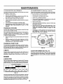
AIR FILTER (See Fig. 17)
Your engine will not run properly using a dirt,,, air filter.
Clean the foam pre-cleaner after every 25 hours of operation or every season. Service paper cartridge every 100
hours of operation or every season, whichever occurs first.
Service air cleaner more often under dusty conditions.
•
Loosen knob and remove cover=
TO SERVICE PRE-CLEANER
° Slide foam preocleaner off cartridge.
,
Wash it in liquid detergent and water.
•
Squeeze it dry in a clean cloth.
•
Saturate it in engine oil. Wrap it in clean, absorbent
cloth and squeeze to remove excess oil.
TO SERVICE CARTRIDGE
•
Remove nut and cartridge plate.
•
Gently tap the flat side of the paper cartridge to dislodge dirt. Do not wash the paper cartridge or use
pressurized air, as this will damage the cartridge.
Replace a dirty, bent, or damaged cartridge.
°
Reinstall the pre-cleaner (cleaned and oiled) over the
paper cartridge.
•
Check rubber seal for damage and proper position
around stud. Replace if necessary.
° Reassemble air cleaner, cartridge plate, and nut.
•
Reinstall air cleaner cover and secure by tightening
knob_
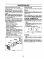
IN-LINE FUEL FILTER
CLAMP
CLAMF
FUEL RLTER
FIG. 18
CLEANING
°
Clean engine, battery, seat, finish, etc. of all foreign
matter.
° Keep finished surfaces and wheels free of all gasoline,
oil, etc.
•
Protect painted surfaces with automotive type wax.
We do not recommend using a garden hose to clean your
tractor unless the electrical system, muffler, air filter and
carburetor are covered to keep water out. Water in engine
can result in a shortened engine life_
CARTRIDGE
FOAM
PRE-CLEANER
CARTRIDGE
RUBBER
SEAL
PLATE _
(See Fig. 18)
The fuel filter should be replaced once each season, if fuel
filter becomes clogged, obstructingfuel flow to carburetor,
replacement is required.
•
With engine coot, remove filter and plug fuel line
sections.
° Place new fuel filter in position tn fuel line with arrow
pointingtowards carburetor.
°
Be sure there are no fuel line leaks and clamps are
propedy positioned.
Immediately wipe up any spilled gasoline.
FIG. 17
2O
SERVICE
D ADJUSTMENTS
i
............................................
i i
i
Ii
i
.......................................TS;
...............
..........
i,i
CAUTION: BEFORE PERFORMING ANY SERVICE OR ADJUSTMEN
= Depress clutch/brake pedal fully and set parking brake.
= Place motion control leyer in neutral (N) position.
= Place attachment clutch in 'DISENGAGED" position.
= Turn ignition key "OFF" and remove key.
Make sure the blades and all moving parts have completely stopped.
•
Disconnect spark plug wire from spark plug and place wire where it cannot come in contact with
plug.
TRACTOR
TO LEVEL MOWER HOUSING
Adjustthe mower while tractoris parked on level ground or
driveway. Make sure tires are properly inflated (See
"PRODUCT SPECIFICATIONS" on page 3 ofthis manual).
If tiresare over or undednflated,you willnot properly adjust
your mower.
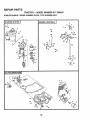
TO REMOVE MOWER (See Fig. 19)
.
Place attachment clutch in "DISENGAGED" position,
o
.
Turn height adjustment knob to lowest setting.
Lower mower to its lowest position.
°
Remove retainer spring holdinganti-swaybar to chassis bracket and disengage anti-swaybar from bracket.
Remove retainer springs from suspension arms at
deck and disengage arms from deck,
°
°
Raise attachment lift to its highest position.
o
Remove two retainer springs from each front link and
remove links.
Slide mower forward and remove belt from electric
clutch pulley,
•
SIDE-TO-SIDE ADJUSTMENT (See Figs. 19 and 20)
°
Raise mower to its highest position_
•
Measure height from bottom of deck curl to ground
level at front comers of mower. Distance "A" on both
sides of mower should be the same.
° Slide mower out from under right side of tractor,
IMPORTANT; IF AN ATTACHMENT OTHER THAN THE
MOWER DECK IS TO BE MOUNTED ON THE TRACTOR,
REMOVE THE FRONT LINKS.
•
If adjustment is necessary, make adjustment on one
side of mower only.
°
To raise one side of mower, tighten lift linkadjustment
nut on that side.
°
To lower one side of mower, loosen lift link adjustment
nut on that side.
NOTE: Each half turn ofadjustment nut willchange mower
height about 3/16".
Recheck measurements after adjusting.
TO INSTALL MOWER
BOTTOM
OF CURL
Follow procedure described in "INSTALL MOWER AND
DRIVE BELT" in the Assembly section of this manual.
ADJUSTMENT
NUTS
LIFT
LINKS
_"--"_'-]
....
FRONT
SUSPENSION
SUSPENSION
ARMS
BOTTOM
OF CURL
FIG. 20
FRONT
MOWER
BRACKET
CHASSIS
BRACKE
FRONT
SUSPENSION
BRACKET
ELECTRIC
CLUTCH
PULLEY
LINKS
RETAINER
SPRINGS
RETAINER
SPRING
FRONT
MOWER
BRACKET
ANTI-SWAY
BAR
RETAINER
SPRINGS
FIG. 19
21
E AND ADJUSTMENTS
iiilllllllllUl
lU,i, i,iiiilll
TO REPLACE
FRONT-TO-BACK ADJUSTMENT (See Figs°21 and 22)IMPORTANT= DECK MUST BE LEVEL SIDE-TO-SIDEo IF
THE FOLLOWING FRONT-TO-BACK ADJUSTMENT IS
NECESSARY, BE SURE TO ADJUST BOTH FRONTLINKS
EQUALLY SO MOWER WELLSTAY LEVEL SIDE-TO-SIDE
,i,ii1,,11, i
ii
MOWER DRIVE BELT
MOWER DRIVE BELT REMOVAL (See Fig. 23) ,
Park tractor'on a level surface. Engage parking brake.
° Remove four screws from LH. mandrel cover and
remove cover.
To obtain the best cutting results, the mower housing
shouldbe adjusted sothe front is approximately1/8" to 1/2"
lower than the rear when the mower is in its highest
position.
Check adjustment on r_ghtside of tractor. Measure distance "F" directly in front of and behind the mandrel at
bottom edge of mower housing as shown.
,
Before making any necessary adjustments, checkthat
both front links are equal in length.
•
If links are not equal in length, adjust one linkto same
length as other link.
° To lowerfront of mower housing, loosennut"G"on both
front linksan equal number'of turns.
•
When distance =F" is 1/8" to 1/2" lower at front than
rear, tightennut"H" againsttrunnionon bothfront links.
,
To raise front of mower housing, loosen nut "H" from
trunnionon both front links° Tighten nut "G" on both
front links an equal number of turns.
•
When distance "F" is 1/8" to 1/2" lower at front than
rear, tighten nut "H" against trunnion on both front
links.
°
Roll belt over the top of LH. mandrel pulley.
°
•
Remove belt from electric clutch pulley..
Remove belt from idler'pulleys.
°
Remove any dirt or'grass clippings which may have
accumulated around mandrels and entire upper deck
surface.
°
Check primary idler arm and two idlers to see that they
rotate freely.
°
Be sure spring is securely hooked to primary idler arm
and bolt in mower housing,
MOWER DRIVE BELT INSTALLATION (See Fig. 23) °
Install belt in both idlers. Make sure belt is in both belt
keepers at the idlers as shown.
NOTE: Each full turn of nut "G" wilt change dim. "F" by
approximately 3/8"o
o Recheck side-to_sideadjustment.
o
,,
Install new belt onto electric clutch pulley,
Roll belt into upper groove of L.H. mandrel pulley.
o
Carefully check belt routing making sure belt is in the
grooves correctly and inside belt keepers.
Reassemble L,H. mandrel cover_
°
L,H,
MANDREL
SCREWS
IDLER
PULLEYS
SPRtNG
ELECTRIC
CLUTCH
PULLEY
PRIMARY
IDLER ARM
FIG. 21
BOLT IN
MOWER
HOUSING
BOTH FRONT'LINKS SHOULD BE EQUAL IN LENGTH
MANDREl
MOWER
DRIVE
BELT
BELT
KEEPERS
FIG. 23
FRONT LINKS
FIG. 22
22
SERV
&,
'11'""111111 I
ADJUSTMENTS
N ..........................
, .......
,i,,
TO REPLACE
(See Fig. 24)
MOWER
BLADE DRIVE BELT
Park the tractor on level surfacer Engage parking brake.
= Remove mowerddve belt (See'q'O REPLACE MOWER
DRIVE BELT" in this section of this manual).
o Remove mower (See "TO REMOVE MOWER" in this
section of this manual).
o Remove screwsfrom R,Ho mandrel coverand remove
cover. Unhook spdng from bolt on mower housing.
=
Carefully roll belt off R.H. mandrel pulley.
o
Remove belt from center mandrel pulley, idler pulley,
and Loll. mandrel pulley.
ii
IIf'l
i,, iii
,
,i,,
NOTE: After installinga new electric clutch, run tractorat
full throttle and engage and disengage electric clutch 10
cycles to wear in clutch plate.
CLUTCH PLATE
NYLON t.OCKNUT (3)
BRAKE PLATE
=
Remove any dirt or grass which may have accumulated around mandrels and entire upper deck surface.
o
Check secondary idler arm and idler to see that they
rotate freely.
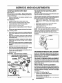
TO ADJUST
°
Be sure spring is hooked in secondary idler arm and
sway-bar bracket.
Your tractor is equipped with an adjustable brake system
which is mounted on the side of the transaxleo
°
Install new belt in lower groove of LoHomandrel pulley,
idler pulley, and center mandrel pulley as shown.
if tractor requires more than six (6) feet stopping distance
at highspeed in highestgear, then brake must be adjusted°
°
Roll belt over RoHomandrel pulley. Make sure belt is in
all grooves properly.
o
Depressclutchibrakepedal and engage parkingbrakeo
•
•
Reconnect spring to bolt in mower housing and rein-,
stall R.H, mandrel cover.
Measure distance between brake operating arm and
nut 'W' on brake rod.
°
°
Reinstall mower to tractor (See "INSTALL MOWER
AND DRIVE BELT" in the Assembly section of this
manual)°
Ifdistance isotherthan 1_1/2",loosen jam nut and turn
nut "A" until distance becomes 1-1/2". Retighten jam
nut against nut "A",
°
•
Reassemble mower drive belt (See "TO REPLACE
MOWER DRIVE BELT" in this section of this manual).
Road test tractor for proper stopping distance as stated
above. Readjust if necessary. If stopping distance is
still greater than six (6) feet in highest gear, further
maintenance is necessary. Contact your nearest authorized service center/department,
LH. MANDREL
MOWER BLADE
DRIVE BELT
FIG. 25
CENTER
BRAKE (See Fig. 26)
WITH PARKING BRAKE "ENGAGED"
NUT"A"
IDLER ARM
_JAM
SPRING'
SWAY BAR
BRACKET
IDLER
PULLEY
FIG. 24
TO ADJUST ATTACHMENT
(See Fig. 25)
CLUTCH
FIG, 26
The electric clutch should provide years of service. The
clutch has a built-in brake that stops the pulley within 5
seconds. Eventually, the internal brake will wear which
may cause the mower blades to notengage, or, to not stop
as required. Adjustments shouldbe made byyour nearest
authorized service center/department.
° Make sure attachment clutchand ignitionswitches are
in "OFF" position.
°
Adjust the three nylon Iocknuts until space between
clutch plate and rotor measures .012" at all three slot
locationscut in side of brake plate.
23
NUT
ii1,1
i,i
....................
:"'IILI'"III'II ,,ill ,,llll
A
_....._._
ii,
I,I,lU
,,i, I
i
I
If for any reason the motion control lever will not hold its
positionwhileat a selected speed, itmay be adjusted at tile
friction pack located on the right side of chassis_
° Park tractor on level surface. Stop tractor by turning
ignition key to "OFF" position and engage parking
brake.
Remove mower (See 'q'O REMOVE MOWER" in this
section of this manual°)
BELT REMOVAL •
o
Engage parking brake (creates slack in belt).
Remove belt from clutching and fan idler pulleys.
°
=
Loosen belt keeper above transaxle pulley.
Remove belt from transaxle pulley_
°
Remove belt from engine pulley and front V-idler pulley.
°
Pullbelt out of all belt keepers and removefrom tractor.
BELT INSTALLATION -
Route belt on left side, coming from engine pulley,
towards back of tractor and through loop in mtdspan
belt keeper.
°
Place V part of belt into grooves on transaxle and fan
idler pulleys, making sure to routebelt inside of all belt
keepers.
°
°
Retighten belt keeper above transaxle pulley.
Place belt around clutching idlers as shown, making
sure to route belt inside of all belt keepers,
°
Place motion control lever in neutral (N) position.
o
°
While holding Iocknut, loosen jam nut
Tighten Iocknut 1/4 turn.
°
While holding Iocknut, tighten jam nut securely.
NOTE= If for any reason the effort to move the motion
control lever' becomes too excessive, reverse the above
adjustment procedure by loosening locknut 1/4 turn.
Place V part of belt into grooves on engine pulley and
front V-idler, making sure to route belt inside of all belt
keepers.
Route belt on dght side, coming from V-idler, towards
back of tractor, above midspan belt keeper and to top
of transaxle pulley.
°
LEVER
The motion controllever has been preset at the factory and
adjustment should not be necessary.
,
°
iii1!11,111 ii,
TO ADJUST MOTION CONTROL
(See Fig. 28)
MOTION DRIVE BELT
Park the tractor on level surface. Engage'parkingbrake.
For ease of service there is a belt installationguide decal on
bottom of left footrest.
°
I' II
ADJUSTMENTS
......................
TO REPLACE
(See Fig. 27)
,llll
Road test tractor after adjustment and repeat procedure if
necessary,
LOCKNUT
JAM NUT'
FIG. 28
°
Check to be sure belt is positioned correctly and is on
proper side of all belt keepers.
° Reinstall mower.
IMPORTANT; CHECK BRAKE ADJUSTMENT.
TRANSMISSION
Should your transmission require removal for service or'
replacement, tt shouldbe purged after reinstatlationbefore
operating the tractor. See "PURGE TRANSMISSION" in
Operation section of this manual°
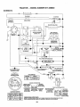
TRACTOR V-BELTDRIVE SCHEMATIC
VIEWED FROM LH. SIDE OF TRACTOR
CLUTCHING
CLUTCHING
ENGINE
PULLEY
V4DLER
REMOVAL/REPLACEMENT
TRANSAXLE
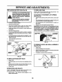
TO ADJUST STEERING
BELT
WHEEL ALIGNMENT
if steering wheel crossbars are not horizontal (left to right)
when wheels are positionedstraightforward, remove steeringwheel and reassemble per instructionsin the Assembly
section of this manual
KEEPER
FRONT WHEEL TOE-IN
ADJUSTMENT
Front wheel toe-in isrequired for preper steering operation.
Toe-in was set at the factory and adjustment shouldnot be
necessary. If parts in the front axle or steering mechanism
have been replaced or damaged, check toe-in and-adjust
if necessary°
I TWISTS
BELT
BELT
KEEPER
FAN
IDLER
TO CHECK TOE-IN (See Fig. 29)°
Positionfront wheels straight ahead.
°
Measure distance between wheels at front and rear of
tires (dimensions "A" and "B").
°
Front dimension "A" should be 1/8" to t/4" less than
rear dimension =B"_
AS VIEWED FROM BO'I-rOM
FIG. 27
24
A DA
ENTS
,i i
7T:_: _
.................
I'
I
AuTioN
..................
: Lead-acid
batteries gener-
Adjust tie rod until dimenston"A" is 1/8" to 1/4" less than
dimension B.
Tighten jam nuts securely.
!_
1111!
TO START ENGINE WITH A WEAK BATTERY
See Fig. 32)
TO ADJUST TOE-IN (See Figs. 29 and 30) o Loosen jam nuts at adjustment sleeves on tie rod.
•
"'11 '1"1'11'
and smoking materials away from batate
explosive
gases.
Keep
sparks,
flame
teries.
Always
wear
eye
protection
when around batteries.
S
......
,
_,,r_l
I
If your battery is too weak to start the engine, it should be
recharged° (See "BATTERY" in the MAINTENANCE section of this manual).
If "jumper cables" are used for emergency starting, follow
this procedure:
IMPORTANT: YOUR TRACTOR IS EQUIPPED WITH A 12
VOLT NEGATIVE GROUNDED SYSTEM, THE OTHER
VEHICLE MUST ALSO BE A 12 VOLT NEGATIVE
GROtJNDED SYSTEM. DO NOT USE YOUR TRACTOR
BATTERY TO START OTHER VEHICLES,
FIG. 29
ADJUSTMENT
SLEEVES
TO ATTACH JUMPER CABLES °
JAM
TtE ROD
°
FIG. 30
FRONT WHEEL CAMBER
°
The front wheel camber ts not adjustableon yourtractor_ If
damage has occurred to affect the front wheel camber,
contact your nearest authorized service center/department.
Connect each end of the RED cable to the POSITIVE
(+) terminal of each battery, taking care not to short
against chassis.
Connect one end of the BLACK cable to the NEGATIVE (_) terminal of fully charged battery.
Connect the other end of the BLACK cable to good
CHASSIS GROUND, away from fuel tank and battery.
TO REMOVE CABLES, REVERSE ORDER °
BLACK cable first from chassis and then from the fully
charged battery.
°
RED cable last from both batteries.
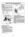
TO REMOVE WHEEL FOR REPAIRS
FRONT WHEEL (See Fig. 31) •
Block up axle securely.
Remove axle cover, retaining ring and washersto allow
wheel removal.
•
°
Repair tire and reassemble.
Replace washers and snap retaining ring securely in
axle groove.
°
Replace axle cover.
"POSITIVE"
"NEGATIVE"
' LH._,
REAR WHEEL °
(+)
Block rear axle securely°
°
°
Remove five (5) hub bolts to allow wheel removal.
Repair tire and reassemble. Replace and tighten hub
bolts securely.
NOTE: To seal tire punctures and prevent flat tires due to
slow leaks, tire sealant may be purchased from your local
parts dealer. Tire sealant also prevents tire dry rot and
corrosion.
.......
FIG. 32
RETAINING
RING
AXLE
COVER
FIG. 31
25
(-)
AND ADJU
REPLACING
TO REPLACE
BATTERY (See Fig, 33)
Replace with 30 amp automotive-type plug-in fuse. The
fuse holder is located behind the dash.
nals by allowing a wrench oranyoth_i" ....
object to contact both terminals at the
same time. Before connecting battery,
remove metal bracelets, wristwatch
bands,rings,etc.
TO ADJUST ATTACHMENT
(See Fig. 34)
Positive terminal must be connected
first to prevent sparking from accidental grounding.
,
Remove terminal guard°
=
Disconnect BLACK battery cable then RED battery
cable and carefully remove battery from tractor_
=
Install new battery with terminals in same position as
old battery.
=
°
Reinstall terminal guard.
First connect RED battery cable to positive (+) battery
terminal with hex bolt and keps nut as shown. Tighten
securely,
,
•
•
FUSE
LIFT SPRING
°
While holdingspringbushing with wrench, loosen jam
nut.
°
Turn adjustment bolt clockwise to extend spring and
reduce lift effort for heavier attachments.
°
Turn adjustment bolt counterclockwise for lighter attachments.
•
Retighten jam nut against spring bushing.
IMPORTANT:
DO NOT ADJUST FOR MAXIMUM SPRING
TENSION WHEN USING LIGHT ATTACHMENTS
SUCH
AS A MOWER. ADJUST LIFT LEVER SPRING TO AID IN
LIFTING ATTACHMENT. DO NOT OVERPOWER SPRING.
WHEN REMOVING ATTACHMENT,
ALWAYS ADJUST
SPRING TENSION TO ITS LOWEST POSITION.
ADJUSTMENT
BOLT
ATTACHMENT
LIFT SPRING
Connect BLACK grounding cable to negative (-) battery terminal with remaining hex bolt and keps nut.
Tighten securely
Close terminal access doors.
SPRING
BUSHING
JAM NUT
Close hood.
TERMINAL
ACCESS
FIG. 34
NUT
HEX BOLT
TO REMOVE HOOD AND GRILL ASSEMBLY
(See Fig. 35)
DOOR_
TERMINAL
GUARD
°
Raise hood.
POSITIVE
°
Unsnap headlight wire connector.
CABLE
°
Stand in front of tractor. Grasp hood at sides, tilttoward
engine and lift off of tractor,
°
To replace, reverse above procedures.
NEGATIVE
(BLAC_
CABLE
HEADUGHT
FIG. 33
ECTOR
TO REPLACE
HEADLIGHT
BULB
°
Raise hood°
°
Pull bulb holder out of the hole in the backside of the
grill
Replace bulb in holder and push l_ulb holder securely
back into the hole in the backside of the grill.
Close hood,
°
°
HOOD
FIG. 35
INTERLOCKS
AND RELAYS
Loose or damaged wiring may cause your tractor to run
poorly, stop running, or prevent it from starting_
°
Check wiring_ See electrical widng diagram in the
Repair Parts section.
26
TO ADJUST THROTTLE
(See Fig. 36)
CONTROL
CLOSED FOR
FULL
CABLE
The throttle control has been preset at the factory and
adjustment shouldnot be necessary° Check adjustment as
described below before loosening cable, if adjustment is
necessary, proceed as follows:
= With engine not running, move throttle control lever to
fast position.
= Check that speed controllever is against stop screw. If
it is not, loosen casing clamp screw and pull throttle
cable until lever is against screw. Tighten clamp screw
securely.
CHOKE
CONTROL
CABLE
CLAMP SCREWS
"_,
\
FIG. 37
TO ADJUST CARBURETOR
The carburetor has been present at the factory and adjustment should not be necessary. However, minor adjustment
may be required to compensate for differences in fuel,
temperature, altitude or load. if the carburetor does need
adjustment, see engine manual.
High speed stop tsfactory adjusted° Do not adjust-damage
may result.
IMPORTANT= NEVER TAMPER WITH THE ENGINE
GOVERNOR, WHICH IS FACTORY SET FOR PROPER
ENGINE SPEED. OVERSPEEDING THE ENGINE ABOVE
THE FACTORY HIGH SPEED SETTING CAN BE
DANGEROUS° IF YOU THINK THE ENGINE-GOVERNED
HIGH SPEED NEEDS ADJUSTING, CONTACT YOUR
NEAREST
AUTHORIZED
SERVICE
CENTER/
DEPARTMENT, WHICH HAS PROPER EQUIPMENT AND
EXPERIENCE
TO
MAKE
ANY
NECESSARY
ADJUSTMENTS.
THROTTLE
CONTROL
CABLE
IDLE SPEED
ADJUSTMENT
SCREW
FIG. 36
TO ADJUST CHOKE CONTROL
(See Figs, 36 and 37)
The choke control has been preset at the factory and
adjustment should not be necessary, check adjustmentas
described below before loosening cable, if adjustment is
necessary, proceed as follows:
•
With engine not running, move choke control (located
on dash panel) to full choke position.
•
Remove air cleaner cover, filter and cartridge plate to
expose carburetor choke (See "AIR FILTER" in the
Customer Responsibilitiessection of this manual).
° Choke should be closed_ If it is not, loosen casing
clamp screw and move choke cable until choke is
completely closed. Tighten casing clamp screw securely.
°
Reassemble air cleaner.
27
ENGINE
Immediately prepare your tractor for storage at the end of
the season or if the tractor will not be used for 30 days or
more..-
FUEL SYSTEM
IMPORTANT:
IT IS IMPORTANT TO PREVENT GUM
DEPOSITS
FROM FORMING
IN ESSENTIAL
FUEL
SYSTEM PARTS SUCH AS CARBURETOR, FUEL FILTER,
FUEL HOSE, OR TANK DURING STORAGE.
ALSO,
EXPERIENCE
INDICATES THAT ALCOHOL BLENDED
FUELS (CALLED GASOHOL OR USING ETHANOL OR
METHANOL) CAN ATTRACT MOISTURE WHICH LEADS
TO SEPARATION AND FORMATION OF ACIDS DURING
STORAGE.
ACIDIC GAS CAN DAMAGE THE FUEL
SYSTEM OF AN ENGINE WHILE IN STORAGE
CAUTION: Never store the tractor with
gasoline in the tank inside a building
where fumes may reach an open flame
or spark. Allow the engine to cool
before storing in any enclosure.
iiriiii.,,,.
TRACTOR
Remove mower from tractor for winter storage. When
mower is to be stored for a period of time, clean it thoroughly, remove all dirt, grease, leaves, etc. Store in a
clean, dry area°
=
,
o
a
NOTE: Fuel stabilizer is an acceptable alternative in
minimizingthe formation of fuel gum deposits during storage. Add stabilizer'to gasoline in fuel tank or storage
container. Always follow the mix ratio found on stabilizer
container. Run engine at least 10 minutes after' adding
stabilizer to allowthe stabilizerto reach the carburetor. Do
not drain the gas tank and carburetor if using fuel stabilizer.
ENGINE OIL
Touch up all rusted or chipped paint surfaces; sand
lightly before painting.
Drain oil (with engine warm) and replace with clean engine
oil. (See "ENGINE" in the Customer Responsibilities
section of this manual).
BATTERY
Fully charge the battery for storage.
After a period of time in storage, battery may require
recharging.
To help prevent corrosion and power leakage during
long periods of storage, battery cables should be
disconnected and battery cleaned thoroughly (see "TO
CLEAN BATTERY AND TERMINALS" in the Customer Responsibilities section of this manual).
After cleaning, leave cables disconnected and place
cables where they cannot come in contact with battery
terminals.
°
=
o
Start the engine and let it run until the fuel lines and
carburetor are empty.
Never useengine or carburetor cleaner productsin the
fuel tank or permanent damage may occur.
Use fresh fuel next season.
=
Be sure that all nuts, bolts and screws are securely
fastened. Inspect moving parts for damage, breakage
and wear. Replace if necessary.
-
Drain the fuel tank,
°
°
Clean entiretractor (See"CLEANING"in the Customer
Responsibilitiessection of this manual)°
Inspect and replace belts, if necessary (See belt replacement instructionsinthe Service and Adjustments
section of this manual).
Lubricate as shown in the Customer Responsibilities
section of this manual.
o
°
CYLINDER(S)
,
Remove spark plug(s).
°
Pour one ounce of oif through spark plug hole(s) into
cylinder(s)_
°
Turn ignition key to"START" position for a few seconds
to distribute oil
°
Replace with new spark plug(s)o
OTHER
If battery is removed from tractor for storage, do not
store battery directly on concrete or damp surfaces.
°
°
Do not store gasoline from one season to another.
Replace your gasoline can if your can starts to rust.
Rust and/or dirt in your gasoline will cause problems.
•
If possible, store your tractor indoors and cover it to
give protection from dust and dirt.
°
Cover your tractor with a suitable protective cover that
does not retain moisture. Do not use plastic. Plastic
cannot breathe which allows condensation to form and
witl cause your tractor to rust.
IMPORTANT: NEVER COVER TRACTOR WHILE ENGINE
AND EXHAUST AREAS ARE STILL WARM,
28
TBOUBLESHOOTMNG
iii
,,i,
,ii
PO
,i,m,l,m,l,l,m,ll
H, I
r'_
PROBLEM
CAUSE
CORRECTION
Will notstart
1,
Out of fuelo
2.
3.
4.
5.
6
7.
Engine not "CHOKED" properly.
Engine flooded.
Bad spark plug,
Dirty air filter,,
Dirty fuel filter.
Water In fuel,
1o
2.
3,
4_
5,
6.
7.
Fillfuel tank.
See "TO START ENGINE"in Operation section.
Waitseveralminutes before attempting tostart,
Replacesparkplug,,
Clean/replaceairftlter_
Replacefuel filter.
Drainfuel tankand carburetor,reflfttank withfresh
gasoline andreplacefuel filter_
8. Checkall wiring.
9. Bee "To AdjustCarburetor"tn ServiceAdjusbl_ents
section,
10. Contactan authorized service centar/department
8. Looseor damagedwiring.
9. Carburetoroutofadjustment.
10° Enginevalvesoutofadjustment.
i
i,l,,i,
,
.............
Herd to start
B. Enginevalves out of adjustment,.
Clean/replacealr fiften
Replacesparkplug.
Rechargeor replacebattery°
Replacefuelfilter.
Drainfuel tank andrefi!lwith freshgasoline.,
Cheekall wiring.
See "To AdjustCarburetor"in ServiceAdjustments
section.
8_ Contactanauthorizedservicecentertdepartment,
1.
2,
3o
4.
5,
6o
7.
8.
94
Clutch/brake pedal not depressed.
Attachment clutch is engaged,
Weak or dead battery,
BIown fuse.
Corroded battery terminals,
Loose or damaged wtdng.
Faulty ignition switch.
Faulty solenaid or starter.
Faulty operator presence switch(es).,
to
2,
3,
4o
5.
6,
7_
8_
9o
Depressclutch/brakepedal.
Disengageattachmentclutch_
Rechargeor replacebattery.
Replacefuse
Cleanbattery terminals.
Checkall wiring.
Check/replaceignitionswitch,
Check/replacesolenoidor starter.
Contactan authorizedservicecenter/deparb'nenL
Engine clicks but wilt not
start
i,,
2.
3o
4.
Weak or dead battery.
Corroded battery termtnaiso
Loose or damaged wiring.
Faulty solenoid or starter,
t.
2.
3.
4_
Rechargeor replacebattary._
Clean battery
termlnals.
Check all widngo
Check/replacesolenoid or starter.
Loss of power
t.
2.
3_
4o
5_
6
7o
8,,
9,
Cutting too much grass/too feet.
Thm_e in "CHOKE" position.
Build-up of grass, leaves and trash under mowen
Dirty air filtar.
Low oil leve!/d{rty oil.
Feutty spark plug.
Dirt! fuel filter,,
Stele or dirty fuel,,
Water tn fuel,,
t.
2.
3,
4,,
5.
6.
7.
8_
g_
Set in "HigherCut"position/reduce
speed.
Adjustthrottle control
Cleanundersideof mowerhousing..
Clean/replaceair filter°
Checkoi1level/changeoil
Cleanandregepor changesparkplug,
Replacefuelfilter,
Drainfuel tank andrefitlwithfresh gasoline.
Drainfuel tankandcarburetor,refiUtankwlthfresh
gasolineand replace fuel filter_
Connectandtighten spark plugwire.
Clean engine air screenifinso
Clean/replacemuffier_
Checkatiwiring.
See "To AdjustCarburetor"in ServiceAdjusb'nents
section.
Contactan authorizedservicecanter/departmenL
ii
i
i i
1.
2,
3.
4.
5.
6.
7,
,l_lj
Enginewill not turn over
ill
1o
2.
3.
4..
5o
6.
7.
Dirty air fiftar,,
Bad spark plug.
Weak or dead battery.
Dtrty fuel filter_
Stale or dirty
fuel.
Loose or damaged wiring.
Carburetor out of adjustment
i
,IL,i,l,llli
Excessivevibration
10_ Spark plugwire loose,
11,, Dirty engine air screenil_nSo
12. Dirtylclogged muffler°
t3.
Loose or damaged wiring.
14o Carburetor out of edJustmenL
10,
11.
12.
13.
t4o
t5_ Enginevalvesout ofadjustment°
15_
1.
2,
3.
Worn, bent or loose blade.
Bent blade mandrel,
Loose/damaged part(s),
t,
2.
3,
29
Replaceblade. Tighten blade bolt.
Replaceblade mandrel.
Tightenloosepart(s). Replacedamagedparts°
TROUB
........................
PROBLEM
HOOTING POINTS
I
'"
III
'111
I'1'11
'1111"1 III .................
CAUSE
I'111 I II '"1
" I1'
"1 iii
II III
' I'1'
'" II
'
I
.....
CORRECTION
1,, Faultyoperator-safety
presence
control
system_
1_ Check widng,switchesand connections If not
corrected,contactan .authorized
servicecenter/
department.
1o
2.
3.
4.
5.
Worn,bent or iooseblade.
Mower deck notlevel
Buildupofgrass,leaves,andtrashundermower.
Bent blademandrel,
Cloggedmowerdeckventholesfrom buildupof
grass,leaves,andtrasharoundmandrels.
t_
2.
3.
4.
5_
Replace bladao Tighten blade boll
Level mower' deck.
Clean underside of mower housing.
Replace blade mandrel.
Clean around mandrets to open vent holes,
Mowerbladeswill not
rotate
1.
2.
3.
4
Obstruction
in clutchmechanism,
Worn/damagedmowerdrivebell
Frozenidlerpulley.
Frozenblademandrel
1,
2,
3.
4,
Removeobstruc_Jon,
Replacemowerddve bell.
ReplaceIdlerpulley..
Replaceblade mandrel.
Poorgrass discharge
I.
2.,
3
4.
5,
6.
7.
8.
9,
10,,
11,.
Enginecontinues to run
whenoperator leaves seat
with attachmentclutch
engaged
I
i[uJl_
Poorcut-
uneven
Enginespeedtoosiow_
Travelspeed toofast°
Wet grass_
Mowerdecknotlevel
Low/uneventireair pressure
Worn,bentor looseblade,
Buildupofgrass,leavesandtrashundermower_
Mowerdrivebelt womo
Bladesimproperlytnstatied_
improperblades used.
Cloggedmowerdeckventholes from buildupof
grass,leaves,andtrasharound mandrels.
1.
2,
3,
4o
5_
6,
7.
8,
9_
IO°
11.
PlacethrottlecontrolIn "FAST" position.
Shifttoslowerspeed,
hJlowgrasstodrybeforemowtng.
Levelmower deck,,
Checktiresforproperair pressure.
Rsplace/sharpen
blade_Tightenbladebolt.
Cleanundersideof mowerhoustng_
Replacemowerddvebelto
Reinstallbladessharpedgedown.
Replacewithbladeslisted tn thismanual.
Cleanaround mandrelstoopen ventholes,
Headllght(s)not working
Ofso equipped)
1,,
2o
3.
4..
5.
Switch Is"OFF"o
Bulb(s) burned ouL
Faulty light switch,,
LoOSe or damaged widng
BIown fuse_
1.
2.
3o
4,
5.
"rum switch"ON".
Replacebulb(s),,
Check/replaceIlghtswitch,
Checkwtdngandconnections.,
Replacefuse,
Batterywtll not charge
I.
2.
3.
4,
Bad batterycell(s).
Poorcableconnections.
Faultyregulator(ifsoequipped)°
Faultyalternator,
1.
2_
3_
4,
Replacebattery°
ChecWcleaflall connections.
Replaceregulator.
Replacealternator.
Loss of drive
1,. Freewheelcontrolin "disengaged"position.
2. Motiondrivebelt worn,damaged,or broken
3o ,AJrtrappedIn transmission
duringshipment
or servicing_
Engine backfires
when turning engine
"OFF"
Enginethrottlecontrolnot set at "SLOW"
positionfor 30 secondsbeforestoppingenglne_
III1'
30
1_ Piecefreewheel controlIn "engaged"position.
2. Replacemotion ddve bell
3. Purgetransmission.
Move throttle controlto "SLOW"position and aIIow
toIdle for 30 secondsbeforestoppingengine,
I1'1
TRACTOR -- MODEL NUMBER 917.258920
SCHEMATIC
RED
I
BLACK
BATTERY
,.
STARTER
FUSE 3OAMP,
G
J
IGNITION
SWITCH
/7
O
NON-REMOVABLE
CONNECTIONS
HEADLIGHTS
---O--REMOVABLE
E_LAC_
PTO SWITCH
CONNECTIONS
POSITION
CIRCUIT
C+G _,H
ON
_+F,B+E,A+D
ENGINE CONNECTOR
REGULATOR "_
F
ENGINE
(PURPLE WiRE, \
/
SHORTING
RED WIRE)
I_'_1
(WHITE WIRE)
SOLENOID
CARBURETOR_
BLUE WIRE,
WIRE) :_
OIL SENTRY
(GREEN
WIRE)(RED
IGNITION SWITCH
POSITION CIRCUIT
OFF
G+M+L
_,U_UGHT B*,,L
B+ L
RJJN
START
B+L+S
NONE
NONE
TRACTOR CONNECTOR
IGNITION SWITCH
"M" FOR ENGINE _L-L-SHORTING
I_
(BLACK
WIRE)
I1_
I1LJ
"MAKE"
NONE ....
A+Y
H
I_
::
BATTERY
CHARGING
(REDWIRE)
WIREFOR
_1
_11
_
II STARTER
"_J
SOLENOID
(WHITE WIRE)
WIRING INSULATED CLIPS
NOTE: IF WIRING INSULATED CLIPS WERE REMOVED FOR SERVICING OF UNIT,
THEY SHOULD BE REPLACED TO PROPERLY SECURE YOUR WIRING,,
1
q:.
REPAIR PARTS
TRACTOR--
MODEL NUMBER 917.258920
ELECTRICAL
22
!
16
33
-"
32
3t
l
I
1
!
32
,51
REPAIR PARTS
TRACTOR - - MODEL NUMBER 917.258920
ELECTRICAL
KEY
NO.
1
2
7
8
9
10
11
!2
16
21
22
25
26
27
28
29
3O
31
32
33
40
41
45
46
47
5O
51
PART
NO.
145425
74760412
7697J
7603J
109596X
145211
150109
145769
t53664
136850
4152J
154335
I08824X
73510400
157899
121305X
140301
124211X
141226
109310)(
156163
17720408
122822X
110940X
17011008
154963
140405
DESCRIPTION
Battery
Bolt Hex Head 1/4-20 x 3/4
Tube Plastic
Tray, Battery
Clamp, Hose
Bolt Wet BTR 1/4-20 x 7.5 Zinc
Hold down Battery Front Mount
Nut Push Nylon 1/4" Wet Battery
Switch Interlock Push-in
Harness Socket Light W/4152J
Bulb Light
Cable/Boot Asm. CV25 w116 Wire
Fuse
Nut Keps Hex 1/4-20 Unc
Cable Battery 4 Gauge 3/8 Term
Switch, Plunger
Switch, Ign
Nut, ignition Switch
Cover Switch Key
Key
Harness Ign.
Screw 1/4-20 x 1/2
Ammeter
Meter, Hour
Screw
Switch, PTO
Ring Retainer PTO
NOTE: All component dimensions given in U_S. inches
1 inch = 25.4 mm
33
REPAIR PARTS
TRACTOR--
MODEL NUMBER 917,258920
CHASSIS AND ENCLOSURES
18
11
48
47
28
43_, 9
21
17
34
32_
52
16
42
56
91
,
17
45
19
100
68
i
i
2
102
10
7O
7
86
34
15
REPAIR PARTS
TRACT n
CHASSIS
KEY
NO.
= mODEL
NUMBER
917.258920
AND I_F,
JCLo_URES
PART
NO.
1 150253
2 140506
3 136671X558
4 73800700
5 145203
6 157882
7 17720408
8 145166
9 108067X
10 19092016
11 137270
12 137269
13 137271
14 136673X558
t5
136374
16 !21794X
17 17490612
t8
t36373X428
19 19131312
20 STD523710
21 STD541437
22 136670X558
23 17490616
24 145243X558
28 145244X558
29 145349
30 145052
31 145183
32 141315
33 141314
34 142131
36 74780512
37 150672X558
38 STD551025
39 136961
40 15611!
41 17580408
42 72140608
43 136939
44 136940
DESCRIPTION
Rail, Frame RH
Drawbar, Gt
Panel Asm. Side LH
Nut, Lock Hex 7/16 Uric
Dash, Plastic Black
Dash Asm,, Lower
Screw, Thd Cut 1/4-20 x 1/2
Support, Battery
Nut, Pal
Washer 9/32 x 1-1/4 x 16 Ga.
Rivet, Ratchet Male
Washer, Nylon
Rivet, Ratchet Female
HoodAsm., Pnt
Lens, Bar Clear
Cover, Access
Screw, Thdrol 3/8-t6 x3/4
Grille
Washer 13/32x t3/16 x 12 Ga.
Bolt, Fin Hex 3/8-!6 x I
Nut, Crownlock 3/8-16 Unc
PanelAsm. Side RH
Screw Thdrol 3/8-16 x I Ty-Tt
Footrest, RH
Footrest, LH
Bracket, Support Dash
Saddle, Hydro 1995
Brace, Support Steering
Bracket Asmo, Frame Pivot Lh
BracketAsm., Frame Pivot Rh
Bracket, Engine Support Rear
Bolt, Fin Hex 5/16-18 x 3/4
Fender, Pnt.
Washer 9/32 x 3/4 x 16 Gan
Bracket, Axle Front
Bracket, Support Axle/Engine
Screw Tap Tite 1/4-20 x 1/2
Bolt, Carriage 3/8-16 x 1
Bracket, Spnsn Front Lh
Bracket, Spnsn Front Rh
KEY
NO.
PART
NO.
45
47
48
49
50
52
56
57
58
59
60
63
64
68
70
77
84
86
90
91
92
94
95
98
99
100
I01
102
103
I06
120
133
134
135
154913
17490608
154995
154993
152728
STD54!431
154914
73640400
137113
74180412
17490620
19131614
144283
17490508
137159
137308
142992
74760716
11050600
156586
156282X011
100207K
105531X
140503
140871
124236X
17490628
4497H
142273
138776
19131616
150542
150543
152923
--
8022J
DESCRIPTION
Bracket Asm., Susp Chassis Rh
Screw Thdrol 3/8-16 x 1/2
Bracket Asm., Pivot Hood Lh
Bracket Asm., Pivot Hood Rh
Bracket, Chassis Front
Nut, Crownlock 5/16-18
Bracket Asmo, Susp Chassis Lh
Nut, Keps Hex 1/4-20
Bracket Asm, Fender
Screw, Mach Cr 1/4-20 x 3/4
ScrewThdrol 3/8-16 x 1-1/4
Washer 13/32 x 1 x 14 Ga.
Washer, Serrated Disc 13/32 x 1
Screw, Thd 5/16-18 x 1/2
Guide, Belt Mid Span
Shield, Front
Stop, Over Center Mower
Bolt, Fin Hex 7/16-14 Unc x 1
Washer, Lock External Tooth 3/8
Rail, Frame Lh
Plate, Silkscreen Dash
Clip, Fuel Line
Push Nut, Nylon
Bracket SkidChassis
Rod By Pass
Cap By Pass Rod
Screw Thdrol 3/8-16 x 1-3/4
Retainer, Spring
Lock, By Pass
Bolt 5/16-18 Type TT
Washer 13/32 x 1 x 16 Ga.
Skirt w/Insert Fender VGT RH
Skirt w/Insert Fender VGT LH
Screw Hex Head Sems #10_24 x 3/
4Gro2
Plug, Hole
NOTE; All component dimensions given in U,So inches
1 inch = 25°4 mm
35
REPAIR PARTS
TRACTOR-
- _/]L!i)C.L
GROUND DRIVE
36
_LIMBER 917.258920
REPAIR PARTS
TRACTOR - - MODEL NUMBER 917.258920
GROUND
DRIVE
KEY
NO.
PART
NO.
2
3
5
6
7
9
15
17
20
22
23
28
29
30
33
34
35
36
37
38
39
40
41
42
46
47
48
50
51
52
53
54
55
56
58
61
64
65
66
67
68
69
70
71
7070E
7563R
STD541437
STD561210
1405O7
140080
STD551037
140921
73940800
156103
13O564
STD541237
140494
19131616
12000053
124236X
137648
149412
121749X
150035
74321016
530_J
73631000
8883R
145'I70
138228
72110612
131494
STD541_37
139123
207J
156563
105706X
140218
74760724
140488
154752
67609
140296
19131312
5142H
123800X
151146
151179
DESCRIPTION
Key 1/4 x 2.5
Washer Thn_stAxle Harden
Nut Crownlock 3/8-16
Pin Cotter 1/8 x 3/4
Wheel Hub Asm.
Bolt Hub
Washer t3/32 x 13/16 x 16 Ga
Spring Rod Brake
Nut Hex Jam Toplock 1/2-20
Shift Arm Asm
Knob
Nut
Brake Rod
Washer 13/32 x 1 x 16 Ga.
Ring E
Cap Parking Brake
Rod Parking Brake
Spring Drive Ground
Washer 25/32 x 1-1/4 x 16 Gauge
Nyliner
Screw Fin #t0-24 x 1
Actuator Interlock Switch
Nut Lock #10-24
Cover Pedal
Retainer Spring
Clutch Rod
Bolt Carriage 3/8-16 x I-1/2 Gr 5
Pulley Idler Flat
Nut Crownlock 3/8-16 UNC
Pulley Idler Grooved
Washer Hardened
Arm Asm Idler Clutch
Bearing, Idler
V-Belt
Bolt Fin Hex 7/16-14 x 1-1/2
Pulley Input
Shaft Asm Brake Parking Clutch
Bolt Shoulder
Washer Hardened
Washer 13/32 x 13/16 x 12 Ga
Pin Roll
Washer
Console Hydro Fender
Plate Console Shift
KEY
NO.
PART
NO.
72
73
74
76
77
78
79
80
81
82
83
84
85
86
87
88
89
90
91
92
93
94
96
98
99
i00
101
104
105
106
t07
108
109
111
t12
113
'115
116
1t7
--
STD541431
74780548
142432
140481
74760716
19111212
7211O505
140484
17490612
150586
140479
140490
17541O2O
140462
14O491
140492
73680700
140489
17490644
7476O520
140502
133835
141103
141OO4
17490624
126881X
156106
140480
17580408
142918
154739
142917
140929
156240
156104
73220700
123405X
73900500
739006O0
150073
DESCRIPTION
Nut Crownlock 5/16-18
Bolt Fin Hex 5/16-18 x 3
Screw Hex Wsho Hi-Lo 114-1/2
Bracket Transaxle
Bolt Fin Hex 7/16-14 x I
Washer 11/32 x 3/4 x 12 Ga
Bolt Carriage 5/16-18 x 5/8
Bracket Torque RH
Screw Thdrol 3/8-16 x 3/4
Bracket Mount Torque/Fan
Strap Torque Mid
Spacer
Screw #10_24 x 1-1/4
Fan 7" Hydro
Adapter Fan
Pulley Idler
Nut Crownlock 7/16-14 UNC
Keeper Belt
Screw Thdrol 3/8-16 x 2-3/4
Bolt Fin Hex 5/16-I8 x 125
Link Shift Asm
Fastner Christmas Tree
Washer Nickel Plated
Bracket Shift
Screw Thdrol 3/8-16 x 1-1/2
Washer Compression
Washer Belfville
Bracket Idler
Screw Tap 1/4-20 x 1/2
O-Ring Asm
Line Fuel
Cap Asm Vent
Spring Return Brake
Spacer Shift Lever Vgth
Washer Nylon High Temp
Nut Hex ASF 7/16-14 UNC
Keeper Belt T/A Gnd. Dr.
Nut Lock Hex Flange 5/16-t 8
Nut Lock Flange 3/8-18 UNC
Transaxle (See Breakdown) Hydro
Gear 218-3010
NOTE: At! component dimensions given in U,S. inches
1 inch = 25°4 mm
37
REPAIR PARTS
TRACTOR
STEERING
- - MODEL
ASSEMBLY
23
22
31
34
33
32
19
27
6
/
/
/'
16
/-
\
\
\
\
\
\
15
14
\
35
14
38
NUMBER
917.258920
REPAIR PARTS
TRACTOR -- MODEL NUMBER 917.258920
STEERING
ASSEMBLY
KEY
NO.
PART
NO,
1
2
3
4
5
6
7
8
9
10
11
12
13
14
15
16
17
121472X
137094
6855M
136960
136959
6266H
121748X
12000029
121232X
7478!044
136518
73901000
121749X
STD551137
STD541537
145103
t37347
18 137155
19 156011
20 145182
21 100711L
22 155105
23 152927
24 19133808
25 STD523710
26 126805X
27 3366R
28 17490612
29 104239X
30 12OO0O34
31 138136
32 19111610
33 STD551131
34 STD523107
35 138059
36 137156
37 73360600
38 109850X
39 73700600
40 109851X
41 155246
42 17490508
DESCRIPTION
Wheel, Steering
Axle Asm., Front
Fitting, Grease
Spindle Asm, LH
Spindte Asm., RH
Bearing, Race Thrust Harden
Washer 25/32 x 1-5/8 x 16 Ga.
Ring, Kiip #T5304_75
Cap, Spindle
Bolt, Fin Hex 5/8-11 x 2-3/4
Spacer, Brgo Axle Front
Nut, Lock Flange 5/8-11 Unc
Washer 25/32 x 1-1/4 x 16 Gao
Washer, Lock Hvy Hlcl Spr 3/8
Nut Lock Center 3/8-24 UNF
Shaft Asm., Steering
Rod Asm., Tie Ball J Ball Vgt (inc.
Key No. 36-40)
Draglink, Ball Joint Solid Vgt
Support Asm,,, Steering Vgt
Column, Steering
Adapter, Wheel Steering
Bushing, Strg. BIk
Screw, TT #10-32.5.3/8. Flange
Washer 13/32 x 2-3/8 x 8 Ga.
Bolt, Fin Hex 3/8-16 x I Gr. 5
Cap, Wheel Steering
Bearing, Col. Strg.
Screw, Thrdrol 3/8-16 x 3/4
Bearing, Flange
Ring, Klip Truarc #5304-75
Bushing, Nyliner Snap
Washer 11/32 x I x 10 Ga.
Washer, Lock Hvy Hicl Spr 5/16
Bolt, Hex Hd 5/16-18 x 3/4
Gear, Sector Steering
Tie Rod
Jam Nut RH Thread
Joint Asm. Ball RH Thread
Jam Nut LH Thread
JointAsm. Ball LH Thread
Bracket Switch interlock
ScrewThdrol 5/16-18 x 1/2 Tyt
NOTE: All component dimensions given in U.S. inches
1 inch = 25_4 mm
39
REPAIR PARTS
TRACTOR - - MODEL NUMBER 917.258920
ENGINE
22
72
64
65
53
73
52
18
._55
15
42
j5
7
10
9
28
26
16
39
38
29
[SPARK
ARRESTER
KIT ]
40
REPAIR PARTS
TRACTOR--
MODEL NUMBER 917.258920
ENGINE
KEY
NO.
PART
NO.
2
5
7
8
9
10
11
12
15
16
17
18
19
150249
13200300
151396
121361X
150828
105432X
140923
143996
151346
109227X
!06082X
152334
132903OO
20
21
22
23
24
25
26
27
28
29
33
37
38
39
40
41
42
43
45
47
48
50
52
53
54
55
56
64
65
67
72
73
132756
17720410
132781
19132616
STD551237
73920600
3645J
139277
7634R
132922
STD541437
123487X
74780624
17490636
17490664
126197X
STD551143
'150280
M73030800
142040
19132007
143020
17580408
'143528
19131414
13090336
13090308
17490612
19131614
17490512
150250
153992
DESCRIPTION
Engine (See Breakdown)
Kohler Model CV25SopS69511
Muffler VGT Side Mount 25HP
Elbow STD 90 Degree 3/8 - 18 NPT
Muffler Assembly Guard
Pulley V-Idler
Keeper Asm Belt Engine Vgt 96
Bushing
Clutch Electdc
Pulley Engine
Tank Fuel Rear 3.50 YT/GT
Pad Spacer
Pad Spacer
Cap Asm Fuel W/Gauge
Plug Oil Drain
(Order From Engine Manufacturer)
Control Throttle
Screw Hex Thd Cut 1/4 - 20 X 5/8
Control Choke
Washer 13/32 X 1 - 5/8 X 16 Ga
Lockwasher Ext Tooth 3/8
Nut Keps 3/8 - 24 UNF
Bushing
Stem Tank Fuel
Fuel Line
Spark Arrester Kit
Nut Lock Hex w/Ins 3/8-16 Unc
Clamp Hose
Bolt Fin Hex 3/8-16 Unc x 1-1t2
Screw Tt 3/8-16 x 2-1/4 Unc
Screw Tt 3/8-16 x 4 Unc
Washer 1-1/20D X 15/32 ID X .250
Waher Lock 7/16
Bolt Hex 7/16-20 X 4-1/4 Ga 5
Nut Flange M8-1_25 Non-Lk Zinc
Spacer Engine CV22 Round Pm
Washer 13/32 x 1-1/4 x 7 Ga.
Duct Air VGT Sears Kohler CV22
Screw Tap Tite 1/4-20 x 1/2
Bracket Duct Air Rear Support
Washer Flat 13/32 x 7/8 x 14 Ga.
Nipple Pipe 3/8 Npt x 4-1/2
Nipple Pipe 3/8 Npt x 1.00
Screw Thdrol 3/8-26 x 3/4 Ty-tt
Washer 13/32 x I x 14 Ga°
Screw Thdrol 5/16018 x 3/4 Tyt
Muffler Pre CV25
Shield Heat
NOTE: Allcomponentdimensions
linch = 25°4 mm
41
givenin USoinches
REPAIR PARTS
TRACTOR - - MODEL NUMBER 917.258920
SEAT ASSEMBLY
18
19
÷t/'6
12
KEY
NO.
1
2
3
4
5
6
7
8
10
12
13
PART
NO.
140124
14055 t
140675
! 27018 X
145006
STD541437
124181X
150176
155925
121246X
121248X
KEY
NO.
DESCRIPTION
Seat
Bracket, Pivot Seat
Strap, Fender
Bolt, Shoulder 5/16-18 X .62
Clip, Push In Hinged
Nut,Crownlock 3/8-16 Unc
Spring, Seat Cprsn
Bolt 5/16-!8 UNC x 3/4 w/Sem
Pan, Seat
Bracket, Mounting Switch
Bushing, Snap
14
15
16
17
18
19
20
21
22
PART
NO.
72050411
121249X
123740X
123976X
19171912
!20068X
124238X
153236
STD541431
DESCRIPTION
Bolt, Carriage 1/4-20 X 1-3/8
Spacer, Split
Spring, Cprsn
Nut, Lock 1/4 Lge Fig Gr. 5
Washer 17/32 X 1-3/16 X 12 Ga.
Knob, Seat 1/2-13 Unc
Cap, Spring Seat.
Bolt, Shoulder 5/16-18 Unc
Nut, Crownlock 5/16-18 Unc
NOTE: All component dimensions given in UoSoinches
1 inch = 25.4 mm
42
REPAIR PARTS
TRACTOR-
- MODEL NUMBER 917.258920
DECALS
18
24
6 3
13
715
15
8
9
7
4
24
13
10
8
\
26
20
16
22
11
12
14
KEY
NO.
1
3
4
6
7
8
9
10
11
12
13
14
15
16
PART
NO.
156835
146705
146706
133644
138048
146707
142342
156439
4900J
146790
146711
139346
142241
1467O9
KEY
NO.
DESCRIPTION
Decal
Decal
Decal
Decal
Decal
Decal
Decal
Decal
Decal
Decal
Decal
Decal
Decal
Decal
17
t8
19
20
22
23
24
26
Operating instruction
Hood, Craftsman, RH
Hood, Craftsman, LH
Maintenance
Side Panel
Ins. Hood
Control Movement
Danger
Clutch/Brake
V-Belt Drive Schematic
Chassis, Hydro 50"
V-Belt Schematic
Panel Side
Fender
PART
NO,
150333
t 46710
!38047
140837
149516
106202X
149918
151448
138311
145245
145247
156942
156943
4,!0
KEY
NO.
PART
NO,
1
2
3
4
5
6
7
8
9
10
11
--
59192
65139
148741
8134H
148736X427
6856M
9040H
148738X427
151607
7154J
104757X
144334
DESCRIPTION
Decal, Cap Cnsmr Help Line Srs
Decal, Insert Strg
Decal, Battery
Decal, Grille
Decal, Btry DngdPsn Engo Acme
Reflector, Taillight
Decal, Fender Hyd/Auto Gold Srs
Decal, Grille Garden Tractor IPC
Decal, Handle Left Height Adj. (Lift
Handle)
Pad Footrest
Fastener Pop_in Footrest
Manual, Owner's (Eng)
Manual, Owner's (Span)
DESCRIPTION
Cap, Valve, Tire
Stem, Valve
Tire, Front
Tube, Front (Service Item Only)
Rim Assembly, Front
Fitting, Grease
Bearing, Flange (Front Wheel Only)
Rim Assembly, Rear
Tire, Rear
Tube, Rear
Cap Hub Axle BLK 1.50 x 1.00
Sealant, Tire (10 oz. tube)
NOTE: All component dimensions given in U.S, inches
1 inch= 25.4 mm
43
REPAIR PARTS
TRACTOR--
MODEL NUMBER 917.258920
LIFT ASSEMBLY
35 17
34
7
31
32
72
4
33
4
2
6
25 26
12
16
12
22
12
20
44
19
18
15
REEPAIRPARTS
TRACTOR - - MODEL NUMBER 917.258920
LIFT ASSEMBLY
KEY
NO.
1
2
3
4
5
6
7
8
9
10
11
12
13
14
15
16
17
18
19
20
21
22
23
24
25
26
29
3O
31
32
33
34
35
38
39
40
41
42
43
70
72
PART
NO.
121006X
154389
121002X
12000022
19292016
74780624
125631X
122365X
122364X
2876H
146704
STD624008
139868
140302
STD54t437
674A247
STD541237
143363
STD551037
5328J
STD523710
127218
STD624008
73350800
13O171
73800800
!50233
1 t0807X
STD551037
137150
STD560907
137167
138057
155O97
123935X
!7490512
735406OO
19112410
123934X
145212
110452X
DESCRIPTION
Rod Asmo, Lever
Shaft Asm., Lift Vgt
Lever Asmo, Lift Rh
E-Ring Truarc #5133-87
Washer 29/32 x 1-1/4 x 16 Ga.
Bolt, Fin Hex 3/8-16 x 1-1t2
Grip, Handle Fluted
Button, Plunger
Plunger, Lever Lift
Spring 2-1/8"
Link Lift
Retainer, Spring
Arm, Suspension Vgt
Bearing, Pvt. Lift Spherical
Nut, Crownlock 3/8-16 Unc
Spring Asmo, Assist Lift
Nut, Hex Jam 3/8-16 Unc
Bracket, Spring Assist
Washer 13/32 x 13/16 x 16 Gao
Bolt, Adjust Spring Assist
Bolt, Fin Hex 3/8-16 x 1
Link, Front
Retainer, Spring
Nut, ,Jam Hex 1/2-13 Unc
Trunnion
Nut, Lock W!Wsh 1/2-13 Unc
Trunnion, lnfin. Height
Nut, Special
Washer 13/32 x 5/8 x 16 Gao.
Spring, Compression inf Hgt
Pin, Cotter 3/32 x 1/2
Rod, Adj Lift
Knob, Inf 3/8-16 Unc
Pointer, Pnt Height Indicator
Plug, Hole
Screw Thdrol 5/16-18 x 3/4
Nut, Crownlock 3/8-24
Washer tl/32 x 1-1/2 x 10 Gao
Scale, Indicator Height
Nut, Hex, Flange, Lock
Nut, Push Phos._& Oil
NOTE: All component dimensions given in U.S. inches
1 inch = 25°4 mm
45
REPAIR PARTS
TRACTOR - - MODEL NUMBER 917.258920
MOWER DECK
55
48
45
44
53_
38,
45
48
48
3O
!
47
28---_
27--_
97
29
98
96
36
2
112
45
54
11
23
46
22
21
L
REPAIR PARTS
TRACTOR
- - MODEL
NUMBER
917.258920
MOWER DECK
KEY
NO.
1
2
5
6
7
8
9
10
11
12
13
14
15
16
17
18
19
20
21
22
23
27
28
30
31
32
33
34
35
36
37
38
39
40
42
43
44
45
46
47
PART
NO.
15699O
STD541431
138457
STD624008
130832
850857
STD551137
140296
137380
129895
137553
137152
110485X
140329
106735X
19111016
105304X
123713X
137607
110452X
110509X
STD551037
'132823
'138776
137266
153535
129963
72140610
72110616
72110608
137166
156085
13'1494
136572
STD533107
13646O
122052X
STD541437
74760628
137200
KEY
NO.
DESCRIPTION
Mower Deck Weldment
Nut, Crownlock 5/16-18
Bracket Asm., Sway Bar
Retainer, Spring
Arm Suspension, Rear
Bolt 3/8-24 x 1o25 Gr. 8 Patched
Washer, Lock H_ry 3/8 Unplated
Washer, Hard Blade Mower Vented
Blade (3 Required)
Bearing, Ball #6204 (Mandrel)
Shaft Asm., W/Lower Brg (Includes
Key Noo t2)
Housing, Mandrel 44" Vent
Beadng, Ball Mandrel
Stripper, Mower Round
Rod, Hinge
Washer 11/32 x 5/8 x 16 Gao
Cap, Sleeve
Spring, Torsion Deflector
Bracket, Deflector
Nut, Push
Shield, Deflector Mower
Washer 13/32 x 13/16 x 16 Ga_
Spacer, Spring Stop idler
Screw Thdrol Hex Head
Nut, Fig Top Lock Cntr 9/16
Pulley, Mandrel
Washer, Spacer Mower Vented
Bolt, Carriage 3/8-i6 x 1-1/4
Bolt, Carriage 3/8-16 x 2
Bolt, Carriage 3/8-16 x I Gr. 5
Stiffener, Arm Idler
Keeper, Belt Idler
Pulley, Idler Flat
Pulley, Driven
Bolt, Carriage 5/16-18 Unc x 3/4
Arm, Idler Secondary
Spacer, Retainer
Nut, Crownlock 3/8-16 Unc
Bolt, Fin Hex 3/8_16 Unc x 1-3/4
Cover, Mandrel RH
PART
NO.
48
49
137729
136574
50
137272
51
52
53
54
55
56
58
59
62
63
64
65
66
67
94
95
96
97
98
99
102
103
104
!05
106
107
108
109
110
1tll
112
113
---
'137273
'139245
137789
139573
144959
138687
133957
137644
133943
72110612
191214'14
151831
156009
73930600
STD523710
132274
132273
191714'16
132264
72110614
153390
155986X505
156941
156852
156853
156854
156856
72010505
73980500
72110605
19171216
72110504
158325
143651
DESCRIPTION
Screw, Thd Roll t/4-20 x 5/8
Cover, Mandrel LH
Arm, Idler Primary
Spring, Second,.r/
Pulley, Idler V Groove
Shield, Idler
V-Belt, Mower Primary
V-Belt, Mower Secondary
Spring, Primary'
Wheel, Gauge
Bolt, Shoulder
Washer Hardened
Bolt Carriage 3/8-16 x 1-1/2
Washer 3/8 x 3/4 x 14Ga
Pulley, Flat, Idler5
Keeper, Belt, Idler
Nut, Centerlock 3/8-16
Bolt Fin Hex 3/8-16 UNC x 1
Bracket Asm. Noseroller LH
Bracket Asm. Noseroller RH
Washer t7/32 x 7/8 x 16 Gao
Roller Nose
Bolt, Carriage 3/8-16 x 1-3/4 Gr. 5
Felt Washer
Bar Adjusting Gauge Wheel
Pin Head Pivot
Bracket Pnt Ga,. Whl Asm R. RH 50
Bracket Pnt Gao Wht Asm R. LH 50
Bracket Pnt Ga. Wht Asm F. RH 50
Bracket Pnt Gao Whl Asm FoLH 50
Bolt Carriage 5/16-t8 x 5/8 Blko
Nut Crownlock 5/16-18 BIk.
Bolt Carr. Sqnk 3/8-16 x 5/8 Gro 5
Washer 17/32 X 3/4 X 16 Ga..
Bolt Carriage 5/16 UNC x 1/2
Mower Service
Mandrel Asm. (Includes Key Nos..
8-10, I2-15, 31, 33)
NOTE: All component dimensions given in Uo& inches
1 inch = 25°4 mm
47
REPAIR PARTS
TRACTOR
HYDRO GEAR TRANSAXLE
- - MODEL
NUMBER
917,258920
-- MODEL NUMBER 218-3010
71
9 (2)
(2)
I
!
108
48
REPAIR PARTS
TRACTOR
HYDRO GEAR TRANSAXLE--
KEY PART
NO. NO.
1 142874
2 142875
7 153765
16 142876
20 142877
21 142878
22 142879
33 142929
35 142880
36 142882
37 142883
38 142884
39 142885
40 142886
41 142887
42 142888
43 142889
45 142890
46 142891
47 142892
49 153766
63 142894
64 150818
65
67
6B
69
70
71
142897
142898
142899
142900
142901
142902
- - MODEL
NUMBER
917.258920
MODEL NUMBER 2'18-3010
KEY PART
NO. NO.
DESCRIPTION
Assembly, Housing, LH
Assembly, Housing, RH
Oil Seal °984 x 1.5 x .25
Brake Shaft Assembly
Axle Mounting Horn Assembly
Washer 1.0 x 1.63 x .08
Washer 1nOx 2.06 x °09
Brake Yoke Assembly
Brake Arm
Puck Plate
Brake Puck
Washer 7/80.D. x 7/16 x .060
Nut, Castle 5/16-24
Cotter Pin
Brake Actuating Pin
Hi Pro Key
Spacer
Brake Disc
Bolt 1/4-20x 1-1/2
Bolt 1/4-20 x I
Differential Assembly
Dowel Pin
Reduction Gear,
14Teeth to 38 Teeth
Final Drive Pinion Assembly
Jackshaft
O-Ring
Washer 5/8 X 1-5/32
Washer 7/8 X 1-1/2
Bolt, Hex 5/16-18x3.5
72
73
74
76
77
78
79
81
82
89
91
95
96
103
104
106
108
109
110
tll
112
113
1'17
123
124
129
153767
142904
142905
142907
142908
142909
153768
142910
142911
142912
t53769
142914
153770
142916
142917
142918
142919
142920
142921
150820
150823
150821
150822
150824
150825
153771
DESCRIPTION
Locknut, Hex 5/16-18
Bolt, Hex 5/16-18 x 1-1/2
Hex Cap Screw 5/16-18 x 1
Shoulder Bolt
Freewheel Actuating Arm
Oil Seal .625 x 1.0 x °25
Grease (10 oz. Tube)
Bolt, Hex 5/16-18 x 1-3/4
Bolt 5/16-18 x 4-1/2
Filter, Spin On
Pump, BDU-10L-122
Plug, Straight Thread
600 7/18 SAE x 5/16 Fitting
Washer
Vent Cap Assembly
Fitting O-Ring Assembly
Control Arm
Set Screw
Filter Head
Hose 1/2"
Fitting, 1/211Beaded 90 ° 7/8 SAE
Fitting, 1/2,, Beaded 60 ° 9/16
Fitting, 1/2 Beaded 90 ° 9/16
O Ring
Pinch Clamp
Spring, Long
NOTE: All component dimensions given in UoS. inches
1 inch = 25.4 mm
49
REPAIR PARTS
TRACTOR
-- MODEL
NUMBER
917.258910
HYDRO GEAR PUMP - MODEL NUMBER BU-10L-122
38
<
KEY PART
NO. NO.
DESCRIPTION
1
2
3
4
5
6
8
12
13
14
15
17
19
21
22
23
Shaft, Pump
Ring, Retaining
Bearing, Bali
Spacer
Seal, Lip
Ring, Retaining
Bearing, Cradle
Seal, Lip
Arm, Trunnion
Guide, Slot
Housing Kit, Transmission
Bearing, Thrust, Bail
Center Section Kit
Seat, Lip
Shaft, Motor
Washer', Block Thrust
144569
122716X
122745X
122715X
122700X
122699X
122767X
122717X
122748X
122749X
144571
122770X
153801
122722X
144573
142978
5O
KEY PART
NO. NO,
DESCRIPTION
25
32
37
38
42
43
44
47
53
60
62
63
64
67
127148X
142938
122786X
122718X
144578
144578
144579
122752X
127153X
142977
144581
144582
144583
144584
Swashplate, Variabte
Block Assembly
Pin, Stainless, Headless
Gasket, Center Section
Check Valve Kit
Check Valve Kit
Charge Relief Kit
Screw, Socket Head, Cap
Bypass Valve Kit
Block Spring
O-Ring
Charge Pump Kit
Gerotor Assembly
Screw, Socket Head, Cap
153769
Pump Assembly, Complete
REPAIR PARTS
TRACTOR--
MODEL NUMBER 917.258920
KOHLER ENGINE - MODEL NUMBER CV25S, TYPE NUMBER 69511
CYLINDER HEAD, VALVE AND BREATHER
CRANKCASE
m--
26- "_
__0---27
,d'_
7""_v
!
19
lJ 121,311_,16
II
I-'13._4
15
1
_'_ 20
_--24
l
_ 23
38 37
8 --26
33
I_i
0
.............. --28
o--B
L-31 _\J
51
REPAIR PARTS
TRACTOR--
MODEL NUMBER 917.258920
KOHLER ENGINE - MODEL NUMBER CV25S, TYPE NUMBER 69511
CYLINDER HEAD/VALVE/BREATHER
CRANKCASE
KEY PART
NO. NO.
KEY PART
NO. NO,
t
2
24-318-17
24-755-76
3
4
25-313-02
24-033-03
5
6
7
24-041-23
24-096-15
M-0645020
8
X-75-23
9
10
11
12
13
14
15
16
17
18
19
20
21
22
23
24
X-426-9
24-326-14
12-755-03
12-173-01
24-089-02
235011
24-016-01
24-016-02
24-017-01
24-017=02
24-032-05
24-294-06
24-326-13
12-351-01
24-411-05
24-041-16
24-318-18
24o755-66
25
26
27
24-186-01
24-599-01
M-0640034
28
24-755-74
29
30
31
24-153-12
24-086..32
24-086-16
32
33
24-445-0i
24-755-57
34
35
36
37
38
24-112-12
24-126-44
25-313-02
24-445-02
M-0545016
DESCRIPTION
1
2
3
Head Assembly, #1 Cylinder'
Kit, Valve Cover, Breather
(Includes Key #3, 29 thru 30)
Grommet, Rubber
Kit, Breather Cover with Gasket
(Includes Key Numbers 5 and 6)
Gasket, Breather
Cover, Breather
Screw Hex Flange M6 x 1.Ox 20
4
5
6
7
8
9
(4)
Plug, Hex Head, Allen head
1/8 Pipe
Clamp, Hose (2)
Hose, Breather
Kit, Retainer (4)
Cap, Valve Spring (4)
Spring, Valve (4)
Retainer, Spring (4)
Valve, Exhaust, Standard Size (2)
Valve, Exhaust, ,25 Oversize (2)
Valve, Intake, Standard Size (2)
Valve, intake, _25Oversize (2)
Seal, Valve Stem (2)
Fitting
Hose, Breather
Lifter, Valve (4)
Rod, Push (4)
Gasket, Cylinder Head (2)
Head Assembly, #2 Cylinder
Kit, Valve Train
(Includes Key Numbers 21,25-26)
Arm, Rocker (4)
Pivot, Rocker Arm (4)
Screw Hex Flange M6 x 1.0 x 34
24-522-72
24-294-03
24-067-05
24-067-06
12-380-03
52-139-09
24-874-04
24-108-04
24-018-01
.12-422o10
12-422-09
12-422-.13
12-422-07
12-422-08
12-422-11
12-422-12
/.,1\
_'_, Valve Cover, Plain
(Includes Key Numbers 29 thru 30)
O-Ring
Screw, Shoulder (4)
Screw Hex Flange Mt0 x 1,5 x 90
(8)
Strap, Lifting
Kit, Breather Separator
ncludes Key Numbers 34 thru 38)
pacer'
Bracket, Breather Separator
Grommet, Rubber
Strap, Breather Separator
Screw Hex Flange M5 x 0_8x 16
10
11
12
13
14
15
16
24-012-05
24-144-01
M-0631005
12-032-01
X-25-102
12-380_04
M-0545010
17
18
19
20
21
22
23
24-018-04
24-402-05
24-032-01
12-t53-01
12-123-04
24-126-19
M-0545016
24
25
26
27
12-153-02
24-038-04
24-755-46
12-153-03
DESCRIPTION
Cylinder Block (Use Short BIock)
Fitting
Connecting Rod (Standard) (2)
Connecting Rod (_25) (2)
Pin, Dowel Locating (6)
Plug, Cup
Piston with Ring Set (Standard) (2)
Ring Set (Standard) (2)
Retainer, Piston Pin (4)
Shim, Camshaft, Yellow
Shim, Camshaft, Red
(As Required)
Shim, Camshaft, Black
(As Required)
Shim, Camshaft, White
(As Required)
Shim, Camshaft, Blue
(As Required)
Shim, Camshaft, Green
As Required)
im, Camshaft, Grey
(As Required)
Camshaft
Shaft, Governor Cross
Washer, Plain 6mm
Seal, Governor Cross Shaft
Washer, Plain 1/4
Pin, Hitch
Screw, Hex Flange
M5 x 0.8 x 10 (2)
Retainer, Reed (2)
Reed, Breather (2)
Seal, Oil, Front
O-Ring, Lower Oil Fill Tube
Tube, Oil Fitl
Bracket, Oil Fill Tube
Screw, Hex Flange
M5 x 0°8 x 16
O-Ring, upper Oil Fill Tube
Dipstick Assembly (Includes 26-27)
Kit, OIl Fill Cap (Includes 27)
O-Ring, Dipstick
NOTE: All component dimensions given in U.S.
inches
1 inch = 25°4 mm
(2)
52
REPAIR PARTS
TRACTOR
- - MODEL
NUMBER
917.258920
KOHLER ENGINE - MODEL NUMBER CV25S, TYPE NUMBER 69511
20 19
16
10
12
14
17
0
1
--8
11
8
\
6
I
14
%
\
5
3
/
9"_
2
10
ii
53
ui
i
11
15
...........................
REPAIR PARTS
TRACTOR
-- MODEL
NUMBER
917.258920
KOHLER ENGINE - MODEL NUMBER CV25S, TYPE NUMBER 69511
IGNITION/ELECTRICAL
KEY PART
NO. NO.
1
2
24-162-17
M.0403025
3
4
5
6
X-25-92
24-112-04
24-157.03
M.0639016
7
8
9
10
11
12-112-01
24-025-08
X-42-15
25-403.03
24-086-18
12
236602
!3
14
15
16
12-132.02
48-154-02
12-468-03
12-086-14
17
18
24-085-01
M.0548025
19
20
21
22
23
X-25-63
X-25-92
47-154-0t
24°584.03
M-0560025
24
M-0448010
6
M-0545020
Screw Hex Flange M5 x 0°8 x 20
7
8
9
10
M-0551016
24-063-28
24-063-23
M-0545010
Screw
Baffle,
Baffle,
Screw
11
12
24-063-14
M-0545016
Baffle, Valley, # 2 Side
Screw Hex Flange M5 x 0.8 x 16
13
14
24-063-31
M-0645016
Baffle, Cyiinder Barrel, # 1 Side
Screw Hex Flange M6 x 1.0 x 16
(2)
DESCRIPTION
Screen, Grass
Screw, Hex Cap
M4 x 0°7 x 25 (4)
Washer, Plain 3/16 (4)
Spacer, Fan (4)
Fan
Screw Hex Flange M6 x 1o0 x 16
(2)
Hex Flange M5 x 0.8 x I6
Cylinder Barrel, # 2 Side
Valley, # 1 Side
Hex Flange M5 x 0.8 x 10
(2)
/o\
_acer, Fan (4)
Flywheel Assembly
Key
Rectifier-Regulator
Screw, Phillips Head (2) 11-16 x 7/
8
Connector, Rectifier-Regulator,
3 Contact
Spark Plug (2)
Clip, Cable
Washer, Plain 3/8
Screw, Hex Flange
M10 x 1.5 x 46
Stator, 15 Amp
Screw, Hex Cap
M5 x 0.8 x 25 (2)
Washer, Plain 1/4 (2)
Washer, Plain 3/16 (2)
Clip, Cable
Module, Ignition(2)
Screw, Hex Socket Head M5 x 0°8
15
16
t7
18
19
20
NOT
/o\
24-100-02
--
25-139-16
--
24-113-28
KEY PART
NO. NO.
1
2
3
4
5
6
7
8
9
10
11
12
t3
14
15
M4 x 0.7 x 10
25
NOT
---
24-584-05
_odule, Speed Advance
ILLUSTRATED
24-176-27
Harness, Wire
25-518-28
Lead, Black (4", 18 Gauge,
insulated Grip Barrel Eyelets)
-- 24-113-18
Decal, Grass Screen
- - 24-468-12
Washer, Graphite (4) 5 mm
- - 24-063-27
Baffle, Heat Shield
BLOWER HOUSING & BAFFLES
KEY PART
NO. NO.
..-
P_]_te,Backing, # 1 Side
Nut, Plastic (2)
Spacer'
Bracket, Breather Separator'
Strap, Breather'
Screw, Hex Cap 8-18 x 1/2 (2)
Nut, Plastic (3)
(Included with Blower Housing)
Nut, Plastic (2)
(Included with Blower Housing)
Plug, Button 9/16
(Included with Blower Housing)
Decal, Horsepower
AIR INTAKE
x 25(4)
Screw, Hex Flange
24-146-08
24-I00-02
24412-12
24-126-44
24-445-02
24-086-27
ILLUSTRATED
24-100.0t
DESCRIPTION
24-755-91
25-341-02
24-096_42
12-100_01
24-096-01
230046
24-083-05
24-083-03
24-109-05
24-041-13
24-094-13
24-041-14
24-164.06
24-041-01
M.0651055
DESCRIPTION
Kit, Knob wi Gasket (Includes 2)
Knob, Cover
Cover, Air Cleaner
Wing Nut
Cover, Inner Air Cleaner
Seal
Element, Pre-Cleaner
Element, Air Cleaner
Cup, Fuel Spitback
Gasket, Fuel Spitback Cup
Base, Air Cleaner
Gasket, Air Cleaner Base
Manifold, Intake
Gasket, Intake Manifold (2)
Screw, Hex Flange
M6 x i .0 x 55 (4)
1
2
24-027-32
M-0545016
Housing, Blower'
Screw Hex Flange M5 x 0.8 x 16
NOT ILLUSTRATED
12-I13-53
Decal, Air Cleaner
3
M*0645016
Screw Hex Flange M6 x t..0 x 16
4
5
24-314-05
24-146-11
(_)uard, Flywheel
Plate, Backing, # 2 Side
NOTE: All component dimensions given in UoS. inches
1 inch = 25.4 mm
(2)
54
REPAIR PARTS
TRACTOR
KOHLER ENGINE - MODEL NUMBER
STARTING
SYSTEM
- - MODEL
NUMBER
917,258920
CV25S, TYPE NUMBER 69511
I
ENGINE
CONTROLS
I
3
24
2d 3
23
J,
6-6
_--
7
26
18
8 rf_
_'
22
2__>
_12
_
16
5
14_15
0
_16
14
4-_
1_
®'-3
__1817
12
11 10
9
55
REPAIR PARTS
TRACTOR--
MODEL NUMBER 917,258920
KOHLER ENGINE - MODEL NUMBER CV25S, TYPE NUMBER 69511
STARTING SYSTEM
KEY PART
NO. NO.
DESCRIPTION
1
2
M-0839080
12-098-03
3
4
5
6
7
8
9
10
11
12
13
14
15
16
17
18
M-0841080
52-100-10
52-435502
52-t00-09
12-081-02
12-090-10
24-755-84
12-239-01
12-170-03
12-471-01
52-221-01
52-089-09
52-323-03
52-168-01
12-301-01
52-211-05
21 12.380-01
Pin, governor regulating
22 M-0645025
Screw, hex. flange M6x1.0x25 (2)
23 M-0631005
Washer, plain 6mm (2)
24 25-162-07
Screen, oil
14 24-041-24
Gasket, oil pan
15 24-422-03
Shim, thrust
NOT ILLUSTRATED
24-113-25
Decal, oil cooler'
Screw, hex. flange M8x1.25xS0 (2)
Starter, solenoid shift
(includes 4-18)
Nut, hex. flange M8x1.25
Nut, starter (2)
Solenoid
Nut, starter
Drive, end cap
Lever, starter drive
Kit, starter repair
Drive, pinion
Armature, starter
Frame
Kit, brush (Includes 14)
Spring, brush (4)
Holder; brush
Insulator
Commutator, end cap
Bolt, thru M5x0.Sx99 (2)
ENGINE CONTROLS
KEY PART
NO. NO.
DESCRIPTION
1 24-086-06
Screw, phillipshd, 11-16x3/4 (2)
2 M-0446030
Nut, hex M4x0_7
3 M-0647060
Nut, hex lock M6xi.0 (2)
4 24-090-09
Lever, throttle control
5 M-0401030
Screw, hex. cap M4x0o7x30
6 X-25-72
Washer, plain 1/4 (3)
7 24-089-20
Spring, throttle shaft
8 M-0639016
Screw hex. flange M6x1.0x16
9 M-0545016
Screw, hex. flange M5x0_Sx16 (2)
!0 12-237..01
Clamp, cable (2)
11 24-126-47
Bracket, control
12 24-144-11
Shaft, throttle
13 24-126-17
Bracket, throttle shaft
14 24-11240
Spacer
!5 24-090-I2
Lever, throttle control
16 24_089-18
Spring, governor
17 M-0641060
Nut, hex. flange M6xloO
18 SM-0642025 Screw, hex. flange M6x1.0x25
19 24-090-14
Lever, governor
20 25-158.11
Bushing, throttle linkage
21 24-089-01
Spring, linkage
22 24-079-04
Linkage, throttle
23 25-158-08
Bushing, linkage retaining
24 M-0645016
Screw, hex. flange M6xl.0x16 (2)
25 24-079-10
Linkage, choke
26 25-158-11
Bushing, throttle linkage
27 M-0647060
Nut, hex lock M6xl.0
28 X-25-52
Washer, plain 1/4
29 25-43t-01
Spacer
30 24-090-20
Lever, choke
31 277341
Washer, spring 3/8
OIL PAN/LUBRICATION
KEY PART
NO. NO.
DESCRIPTION
1 24-086-12
Screw, hex. cap M6x1.7x18 (2)
2 24-100-01
Nut, plastic (2)
3 24-594-09
Oil Cooler, (Includes 4)
4 24-326-15
Hose (2)
5 24-136-03
Nipple, oil filter'
6 12-050-01
Filter',oil
7 24-153-13
O-Ring
8 X-75-32
Plug, hex. ctsk. 3/8
9 52-032-08
Seal, oil (PTO end)
10 24-086-17
Screw, hex. flange MSx1.25x45
11 24-086-16
Screw, hex. flange MSx1.25x45 (9)
12 52-t39-02
Plug, drain
13 24-755-59
Kit, oil pan w/gasket
(Includes 14-21,24)
16 24-393-08
Oil pump assembly (Includes 17)
17 24-123-05
Tube, oil pickup
18 12-144-02
Shaft, govemor gear
19 52-448-O2
Tab, locking
20 24-043-12
Kit, governor gear w/pin
(Includes 21)
NOTE: All component dimensions given in UoS. inches
1 inch = 25_4 mm
56
REPAIR PARTS
TRACTOR - - MODEL NUMBER 917.258920
KOHLER ENGINE - MODEL NUMBER CV25S, TYPE NUMBER 69511
10
6
9
13
5
5
5
7
i
i
i
i HHI,,I
57
REPAIR PARTS
TRACTOR--
MODEL NUMBER 917.258920
KOHLER ENGINE - MODEL NUMBER CV25S, TYPE NUMBER 69511
FUEL SYSTEM
KEY PART
NO. NO.
1
2
3
4
5
6
7
8
9
10
11
12
13
14
15
CRANKSHAFT
KEY PART
NO, NO.
DESCRIPTION
24-853-27
Kit, Carburetor with Gasket
(IncludesKey Numbers 2 thru 4)
24-041-15
Gasket, Carburetor
24-053-27
Carburetor Assembly
(For' Information Only,
Not Available Separately)
24-041-14
Gasket, Air Cleaner Base
X-426-9
Clamp, Hose (6) ,,
25-353_03-11 Line, Fuel, 13-1/2 (2)
M-0641060
Nut M6 x 1.0 (2)
M-0629105
Stud M6 x 1.0 x 105 (2)
24-086-t2
Screw, Hex Cap Head (2)
M6x1.7x18
24-393-04
Pump, Fuel, Pulse
24-100-01
Nut, Plastic (2) .
24-353-O3
Line, Fuel, 10-5/8
25-050-03
Filter, Fuel
24-126-53
Bracket, Throttle Stop
M-0259006
Screw Trottle Stop Bracket
1
2
24-014-72
52-139-09
DESCRIPTION
Crankshaft
Plug, Cup
EXHAUST
KEY PART
NO. NO,
1
2
3
24-041-02
M-0829033
M-0841080
DESCRIPTION
Gasket, Exhaust (2)
Stud, M8 x 1.25 x 33 (4)
Nut, Hex Flange M8 x 1.25 (4)
NOT ILLUSTRATED
KEY PART
NO. NO.
--- -
24-755-03
24-522-72
24-0.41-15
RPM Settings:
RPM Settings:
DESCRIPTION
Gasket Set
Short Block
Gasket, Carburetor
Low Speed: 1150-1650
High Speed: 3200-3400
NOTE: All component dimensions given in U.S. inches
1 inch = 25.4 mm
58
SUGGESTED GUIDE FOR SIGHTING SLOPES FOR :SAFE OPERATION
SIGHTING
GUIDE
ONLY RIDE UP AND DOWN HILL,
NOT ACROSS HILL
SIGHT AND HOLD THIS LEVEL WITH
SKY LINE OR TREE.
®
25.0 HP TWiN CYLINDER
ELECTRIC START
50" MOWER
AUTOMATIC
GARDEN TRACTOR
MODEL NO.
917.258920
Each tractor has its own model number'. Each engine has
itsown model number.
The model number for your tractor will be found on the
model plate located under the seat.
The model number for your engine will be found on the
blower housing of the engine.
All parts listed herein may be ordered from any Sears,
Roebuck and Co. Service Center/Department and most Retail Stores.
IF YOU NEED
REPAIR SERVICE
OR PARTS:
WHEN ORDERING REPAIR PARTS, ALWAYS GIVE THE
FOLLOWING INFORMATION:
FOR REPAIR SERVICE, CALL
THIS TOLL FREE NUMBER:
1-800-4-REPAIR
• PRODUCT - TRACTOR
o MODEL NUMBER - 917.258920
(1-800.473-7247)
o ENGINE MODEL NO. - CV25S-PS69511
FOR REPLACEMENT PARTS
iNFORMATION AND
ORDERING, CALL THIS
TOLL FREE NUMBER:
1-800-FON-PART
(1-800-366-7278)
FOR CONSUMER ASSISTANCE
HOT LINE, CALL THIS
TOLL FREE NUMBER:
• PART NUMBER
° PART DESCRIPTION
Your Sears merchandise has added value when you
consider Sears has service units nationwide staffed with
Sears trained technicians,, professional technicians
specifically trained to insure that we meet our pledge to
you, we service what we sell.
1-800-659-5917
156942
Rev. 5
9o11.98
......................................................
KFSW/RH
Printed in U.S.A.
FI
I
....................................................
,
...........