1
WT4070/90 Wearable Terminal
User Guide
WT4070/90 Wearable Terminal
User Guide
72E-87633-02
Rev A
February 2007
ii
WT4070/90 Wearable Terminal User Guide
© 2006-7 Motorola, Inc. All rights reserved.
No part of this publication may be reproduced or used in any form, or by any electrical or mechanical means, without
permission in writing from Motorola. This includes electronic or mechanical means, such as photocopying, recording, or
information storage and retrieval systems. The material in this manual is subject to change without notice.
The software is provided strictly on an “as is” basis. All software, including firmware, furnished to the user is on a
licensed basis. Motorola grants to the user a non-transferable and non-exclusive license to use each software or
firmware program delivered hereunder (licensed program). Except as noted below, such license may not be assigned,
sublicensed, or otherwise transferred by the user without prior written consent of Motorola. No right to copy a licensed
program in whole or in part is granted, except as permitted under copyright law. The user shall not modify, merge, or
incorporate any form or portion of a licensed program with other program material, create a derivative work from a
licensed program, or use a licensed program in a network without written permission from Motorola. The user agrees to
maintain Motorola’s copyright notice on the licensed programs delivered hereunder, and to include the same on any
authorized copies it makes, in whole or in part. The user agrees not to decompile, disassemble, decode, or reverse
engineer any licensed program delivered to the user or any portion thereof.
Motorola reserves the right to make changes to any software or product to improve reliability, function, or design.
Motorola does not assume any product liability arising out of, or in connection with, the application or use of any
product, circuit, or application described herein.
No license is granted, either expressly or by implication, estoppel, or otherwise under any Motorola, Inc., intellectual
property rights. An implied license only exists for equipment, circuits, and subsystems contained in Motorola products.
MOTOROLA and the Stylized M Logo are registered in the US Patent & Trademark Office. Symbol is a registered
trademark of Symbol Technologies, Inc. Bluetooth is a registered trademark of Bluetooth SIG. Microsoft, Windows and
ActiveSync are either registered trademarks or trademarks of Microsoft Corporation. All other product or service names
are the property of their respective owners.
Motorola, Inc.
One Symbol Plaza
Holtsville, New York 11742-1300
http://www.symbol.com
Patents
This product is covered by one or more of the patents listed on the website: www.symbol.com/patents
Getting Started
Revision History
Changes to the original manual are listed below:
Change
Date
Description
-01 Rev. A
09/25/2006 Initial Release
-02 Rev. A
02/22/2007 Add new start up windows, Fusion 2.5 information, 128 MB Flash configuration.
iii
iv
WT4070/90 Wearable Terminal User Guide
Table of Contents
Chapter 1
Table of Contents
Patents........................................................................................................................... ii
Revision History ............................................................................................................. iii
About This Guide
Introduction .................................................................................................................... v
Documentation Set .................................................................................................. v
Configurations................................................................................................................ vi
Software Versions.................................................................................................... vii
Chapter Descriptions ..................................................................................................... viii
Notational Conventions.................................................................................................. viii
Related Documents and Software ................................................................................. viii
Service Information ........................................................................................................ ix
Chapter 1: Getting Started
Introduction ................................................................................................................... 1-1
Unpacking the Wearable Terminal ................................................................................ 1-2
Accessories ................................................................................................................... 1-3
Getting Started .............................................................................................................. 1-5
Installing and Removing the Main Battery .................................................................... 1-5
Installing the Main Battery ....................................................................................... 1-5
Charging the Battery ..................................................................................................... 1-6
Charging the Main Battery and Memory Backup Battery ........................................ 1-6
Charging Spare Batteries ........................................................................................ 1-7
Removing the Main Battery ..................................................................................... 1-7
Installing the Wrist Mount .............................................................................................. 1-8
Connecting a Scanner .................................................................................................. 1-10
Starting the Wearable Terminal .................................................................................... 1-10
Chapter 2: Using the Wearable Terminal
Introduction ................................................................................................................... 2-1
Power Button ................................................................................................................ 2-1
LED Indicators .............................................................................................................. 2-2
Keypads ........................................................................................................................ 2-3
Two-color Alphanumeric Keypad ............................................................................ 2-3
Triple-Tap Alphanumeric Keypad ........................................................................... 2-5
vi
WT4070/90 Wearable Terminal User Guide
Display ..........................................................................................................................
Start Up Window .....................................................................................................
Windows CE 5.0 Desktop .......................................................................................
Status Icons ......................................................................................................
Using the Keypad to Navigate Applications ............................................................
Key Combinations .............................................................................................
Selecting Items .................................................................................................
Navigating Menus .............................................................................................
Navigating Tabs ................................................................................................
Navigating Fields ..............................................................................................
Selecting Checkboxes and Radio Buttons ........................................................
Selecting Items in a List ....................................................................................
Resetting the Wearable Terminal .................................................................................
Performing a Warm Boot ........................................................................................
Performing a Cold Boot ...........................................................................................
Data Capture ................................................................................................................
Laser Scanning .......................................................................................................
Scanning Considerations ........................................................................................
Scanning Bar Codes ...............................................................................................
Scanning Tips ...................................................................................................
Scan LED Indicator .................................................................................................
Waking the Wearable Terminal ....................................................................................
2-9
2-9
2-10
2-10
2-11
2-11
2-12
2-12
2-13
2-13
2-13
2-14
2-14
2-14
2-15
2-16
2-16
2-16
2-16
2-17
2-17
2-18
Chapter 3: Accessories
Introduction ...................................................................................................................
Cradles ....................................................................................................................
Scanners .................................................................................................................
Accessories .............................................................................................................
Single Slot USB Cradle .................................................................................................
Battery Charging Indicators ....................................................................................
Four Slot Ethernet Cradle .............................................................................................
Battery Charging .....................................................................................................
LED Charge Indications ..........................................................................................
Speed LED ..............................................................................................................
Link LED .................................................................................................................
Battery Charging Indicators ....................................................................................
Four Slot Spare Battery Charger ..................................................................................
Spare Battery Charging with the Four Slot Spare Battery Charger ........................
Battery Charging Indicators ....................................................................................
RS409 Scanner ............................................................................................................
RS309 Scanner ............................................................................................................
Wired Headset ..............................................................................................................
3-1
3-1
3-1
3-1
3-2
3-3
3-4
3-5
3-5
3-5
3-5
3-5
3-6
3-6
3-6
3-7
3-9
3-11
Chapter 4: Maintenance & Troubleshooting
Introduction ................................................................................................................... 4-1
Maintaining the Wearable Terminal .............................................................................. 4-1
Wrist Mount Cleaning Istructions ............................................................................ 4-1
Table of Contents
Troubleshooting ............................................................................................................
Wearable Terminal ..................................................................................................
Four Slot Ethernet Cradle .......................................................................................
Four Slot Spare Battery Charger ............................................................................
Single Slot USB Cradle ...........................................................................................
4-2
4-2
4-5
4-6
4-7
Appendix A: Specifications
Technical Specifications ...............................................................................................
Wearable Terminal ..................................................................................................
RS309 Scanner .......................................................................................................
RS409 Scanner .......................................................................................................
Cradles ....................................................................................................................
A-1
A-1
A-3
A-4
A-6
Appendix B: Regulatory
Introduction ................................................................................................................... B-1
Accessory Power Supply Regulatory Compliance ........................................................ B-1
vii
viii
WT4070/90 Wearable Terminal User Guide
About This Guide
About This Guide
Introduction
This guide provides information about using the WT4070/90 family of mobile terminals and accessories.
NOTE
Screens and windows pictured in this guide are samples and can differ from actual screens.
Documentation Set
The documentation set for the WT4070/90 is divided into guides that provide information for specific user
needs.
•
Microsoft Application Guide - describes how to use Microsoft developed applications.
•
Symbol Application Guide - describes how to use Symbol developed applications.
•
WT4070/90 Wearable Terminal User Guide - describes how to use the WT4070/90 wearable terminal.
•
WT4070/90 Wearable Terminal Integrator Guide - describes how to set up the WT4070/90 wearable
terminal and the accessories.
•
SMDK Help File - provides API information for writing applications.
vi
WT4070/90 Wearable Terminal User Guide
Configurations
This guide covers the following configurations:
Configuration
Radios
Display
Memory
Data
Capture
Operating
System
Keypads
WT4070
WLAN: 802.11b/g
WPAN: Bluetooth
2.8” QVGA
Color
128 MB RAM/
64 MB Flash
Optional
accessory
Windows
CE 5.0
Professional
Two-color or
Triple-tap
Alphanumeric
Keypad
WT4090
WLAN: 802.11a/b/g
WPAN: Bluetooth
2.8” QVGA
Color
128 MB RAM/
64 MB Flash or
128 MB RAM/
128 MB Flash
Optional
accessory
Windows
CE 5.0
Professional
Two-color or
Triple-tap
Alphanumeric
Keypad
About This Guide
Software Versions
This guide covers various software configurations and references are made to operating system or software
versions for:
•
OEM version
•
Fusion version.
OEM Software
To determine the OEM software version:
1.
Press CTRL and then ESC to open the Start menu.
2.
Using the navigation keys, select Settings.
3.
Press the Blue key and the down arrow to open the Control Panel sub-menu.
4.
Press ENTER key to launch Control Panel.
5.
Using the navigation keys, select the System Information icon.
6.
Press ENTER key to launch System Information applet.
Fusion Software
To determine the Fusion software version:
1.
Press ALT - w. The Wireless menu appears.
2.
Using the navigation keys, select Wireless Status.
3.
Press ENTER. The Wireless Status window displays.
4.
Press 5. The Versions screen appears.
vii
viii
WT4070/90 Wearable Terminal User Guide
Chapter Descriptions
Topics covered in this guide are as follows:
•
Chapter 1, Getting Started, provides information on getting the wearable terminal up and running for the
first time.
•
Chapter 2, Using the Wearable Terminal, explains how to use the wearable terminal. This includes
instructions for powering on and resetting the wearable terminal, entering and capturing data.
•
Chapter 3, Accessories, describes the accessories available for the wearable terminal and how to use
the accessories with the wearable terminal.
•
Chapter 4, Maintenance & Troubleshooting, includes instructions on cleaning and storing the wearable
terminal, and provides troubleshooting solutions for potential problems during wearable terminal
operation.
•
Appendix A, Specifications, includes a table listing the technical specifications for the wearable terminal.
•
Appendix B, Regulatory, contains the accessory power supply regulatory compliance statements.
Notational Conventions
The following conventions are used in this document:
•
“Wearable terminal” refers to the WT4070/90 series of wearable terminals.
•
Italics are used to highlight the following:
- Chapters and sections in this guide
- Related documents
•
Bold text is used to highlight the following:
- Dialog box, window and screen names
- Drop-down list and list box names
- Check box and radio button names
- Icons on a screen
- Key names on a keypad
- Button names on a screen.
•
Bullets (•) indicate:
- Action items
- Lists of alternatives
- Lists of required steps that are not necessarily sequential.
•
Sequential lists (e.g., those that describe step-by-step procedures) appear as numbered lists.
Related Documents and Software
The following documents provide more information about the WT4090 wearable terminals.
About This Guide
•
WT4090 Quick Start Guide, p/n 72-86717-xx
•
WT4090 Windows® CE 5.0 Regulatory Guide, p/n 72-86718-xx
•
WT4090 Wearable Terminal Integrator Guide, p/n 72E-87638-xx
•
RS309 Scanner Quick Reference Guide, p/n 72-86011-xx
•
RS409 Scanner Quick Reference Guide, p/n 72-86010-xx
•
Symbol Application Guide for Symbol Devices, p/n 72E-68901-xx
•
Microsoft Applications for Windows Mobile and CE 5.0 User Guide, p/n 72E-78456-xx
•
Symbol Mobility Developer Kits, available at: http://support.symbol.com.
•
Device Configuration Package (DCP for WT4090c50) and Platform SDK (PSDK9090c50) for WT4090
with Windows CE 5.0, available at: http://support.symbol.com.
•
ActiveSync software, available at: http://www.microsoft.com.
ix
For the latest version of this guide and all guides, go to: http://support.symbol.com.
Service Information
If you have a problem with your equipment, contact the “Symbol Global Interactive Center,” for your region. Go
to http://www.symbol.com/contactsupport. If you purchased your Symbol product from a Symbol Business
Partner, contact that Business Partner for service.
Before contacting, have the model number and serial number at hand. If your problem cannot be solved by the
Symbol Global Interactive Center, you may need to return your equipment for servicing and you will be given
specific directions.
Motorola is not responsible for any damages incurred during shipment if the approved shipping container is not
used. Shipping the units improperly can possibly void the warranty.
x
WT4070/90 Wearable Terminal User Guide
Getting Started
Chapter 1
Chapter 1
Chapter 1 Getting Started
Introduction
This chapter lists the parts and accessories for the wearable terminal and explains how to install and charge
the batteries and start the wearable terminal for the first time.
Power Button
Display
Charge Status LED
Application
Keypad
Data Entry Keypad
Speaker
Action Keypad
Interface Connector
Rubber Plug
Battery
Battery Release
Cleat
Cradle Connector
Figure 1-1 WT4070/90 Wearable Terminal
Interface Connector
(shown without Rubber
Plug)
1-2
WT4070/90 Wearable Terminal User Guide
Table 1-1 Parts of the WT4070/90
Item
Description
Display
Displays the application and data stored on the device.
Power Button
Places the wearable terminal in to the suspend mode or resumes normal
operation.
Performs a warm boot when held down for five seconds. See Resetting the
Wearable Terminal on page 2-14 for information about performing a warm boot.
Charge Status LED
Indicates the charging status of the battery.
Speaker
Provides audio playback.
Keypads
Enable user input.
Battery
Provides power to the wearable terminal.
Interface Connector
Provides electrical connection to an accessory, such as a scanner.
Cradle Connector
Provides electrical connection to a cradle.
Battery Release
Releases the battery for removal.
Cleat
Provides mounting for the wrist mount and cradles.
Unpacking the Wearable Terminal
Carefully remove all protective material from around the wearable terminal and save the shipping container for
later storage and shipping.
Verify that you received all equipment listed below:
• Wearable terminal
• Lithium-ion battery
• Regulatory Guide
• Quick Start Guide.
Inspect the equipment for damage. If you are missing any equipment or if you find any damaged equipment,
contact the Symbol Global Interactive Center immediately. See page ix for contact information.
Getting Started
1-3
Accessories
Table 1-2 lists the major accessories available for the wearable terminal:
Table 1-2 Wearable Terminal Accessories
Accessory
Description
Single Slot USB Cradle
Charges the wearable terminal main battery and a spare battery. It also
synchronizes the wearable terminal with a host computer through a USB
connection.
Four Slot Ethernet Cradle
Charges up to four wearable terminals (with main battery installed) and provides
communication through an Ethernet connection.
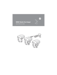
Four Slot Spare Battery
Charger
Charges up to four spare batteries.
RS409 Scanner
Provides scanning capability.
RS309 Scanner
Provides scanning capability.
Wrist Mount
Provides a means for wearing the wearable terminal on the arm for hands-free
applications.
Hip Mount
Provides a means for wearing the wearable terminal on a belt for hands-free
applications.
Headset
For audio playback/recording during voice-enabled applications.
Headset Adapter
Connects an optional headset with a barrel jack connector to the wearable
terminal.
Replacement Batteries
Standard Capacity Battery: 2330 mAh
Software
Symbol Mobility Developer Kits available at: http://support.symbol.com.
Device Configuration Package (DCPforWT40x0c50) and Platform SDK
(PSDK40x0c50) for WT40x0, available at: http://support.symbol.com.
1-4
WT4070/90 Wearable Terminal User Guide
Scan LED
Connector
Rotating Scan Assembly
Exit Window
Ring Mount
Finger Strap
Trigger Assembly
Scan Trigger
Figure 1-2 RS409 Scanner
Protective Cap
Scan LED
Trigger Connector
Interface Connector
Exit Window
Trigger Cable
Scan Button
Interface Cable
Figure 1-3 RS309 Scanner
Getting Started
1-5
Getting Started
In order to start using the wearable terminal for the first time:
• Install the main battery
• Charge the main battery and backup battery
• Install the wearable terminal onto the wrist mount
• Install an optional scanner
• Start the wearable terminal.
NOTE
The main battery can be charged before or after installation into the wearable terminal. Use
the Single Slot USB cradle or Four Slot Spare Battery Charger to charge the main battery
before installation, or the Single Slot USB cradle or Four Slot Ethernet cradle to charge the
main battery after installation.
Installing and Removing the Main Battery
Installing the Main Battery
Before using the wearable terminal, install a lithium-ion (Li-ion) battery by placing the battery into the wearable
terminal as shown in Figure 1-4.
NOTE
Ensure the battery is fully inserted. An audible click can be heard as the battery is fully inserted. A
partially inserted battery may result in unintentional data loss.
When a battery is installed in a wearable terminal for the first time the wearable terminal boots and powers on
automatically.
Figure 1-4 Installing the Main Battery
1-6
WT4070/90 Wearable Terminal User Guide
Charging the Battery
Charging the Main Battery and Memory Backup Battery
Before using the wearable terminal for the first time, charge the main battery until the amber Charge Status
LED remains lit (see Table 1-3 on page 1-6 for charge status indications).
The wearable terminal is equipped with a memory backup battery which automatically charges from the main
battery whether or not the wearable terminal is operating or is in suspend mode. The memory backup battery
retains data in memory for at least 30 minutes when the wearable terminal's main battery is removed or fully
discharged. When the wearable terminal is used for the first time or after the memory backup battery has fully
discharged, the memory backup battery requires approximately 15 hours to fully charge. Do not remove the
main battery from the wearable terminal for 15 hours to ensure that the memory backup battery fully charges. If
the main battery is removed from the wearable terminal or the main battery is fully discharged, the memory
backup battery completely discharges in several hours.
When the wearable terminal reaches a very low battery state, the combination of main battery and backup
battery retains data in memory for at least 24 hours.
NOTE
Do not remove the main battery within the first 15 hours of use. If the main battery is removed before the
backup battery is fully charged, data may be lost.
Charge the wearable terminal with an installed main battery using either the Single Slot USB cradle or the Four
Slot Ethernet cradle.
To charge the main battery:
1.
Ensure the cradle used to charge the main battery is connected to the appropriate power source.
2.
Insert the wearable terminal into a cradle.
3.
The wearable terminal starts to charge automatically. The amber Charge Status LED lights to indicate the
charge status. See Table 1-3 for charging indications. The standard capacity battery fully charges in less
than four hours.
Table 1-3 Wearable Terminal LED Charge Indicators
LED
Indication
Off
Wearable terminal is not in cradle. Wearable terminal not placed correctly. Charger is
not powered.
Fast Blinking Amber
Charging error:
• Temperature is too low or too high.
• Charging has gone on too long without completing (typically eight hours).
Slow Blinking Amber
Wearable terminal is charging.
Solid Amber
Charging complete.
Note: When the battery is initially inserted in the wearable terminal, the amber LED
flashes once if the battery power is low or the battery is not fully inserted.
Getting Started
1-7
Charging Spare Batteries
Use the following accessories to charge spare batteries:
• Single Slot USB Cradle
• Four Slot Spare Battery Charger.
To charge a spare battery:
1.
Ensure the accessory used to charge the spare battery is connected to the appropriate power source.
2.
Insert the spare battery into the accessory’s spare battery charging slot with the charging contacts facing
down (over the charging pins) and gently press down on the battery to ensure proper contact.
3.
The battery starts to charge automatically. The amber charge LED on the accessory lights to show the
charge status. See Chapter 3, Accessories for accessory charge LED indicator definitions.
The standard capacity battery fully charges in less than four hours.
Removing the Main Battery
To remove the main battery:
1.
Prior to removing the battery, ensure that the wearable terminal is in suspend mode. If the wearable
terminal is not in suspend mode, press the Power button to place the wearable terminal in suspend mode.
2.
Press the battery release button. The battery partially ejects from the wearable terminal.
3.
Remove the battery from the wearable terminal.
Battery Release
Figure 1-5 Removing the Main Battery
1-8
WT4070/90 Wearable Terminal User Guide
Installing the Wrist Mount
The wrist mount provides the mounting of the wearable terminal on the forearm for hands-free applications.
Refer to the Wrist Mount Installation Guide for information on the wrist mount.
Mounting Bracket
Release Lever
Figure 1-6 Wrist Mount
To install the wrist mount:
1.
Determine which arm the wrist mount will be used on.
2.
Install the short strap on the end closest to the wrist.
3.
Install the long strap on the other end.
4.
Slide the hand into the wrist mount.
5.
Tighten the straps.
6.
Align the cleat on the back of the wearable terminal with the mounting bracket on the wrist mount.
Mounting Bracket
Figure 1-7 Aligning the Cleat
7.
Slide the wearable terminal onto the wrist mount until it clicks into place.
Getting Started
8.
1-9
If necessary, loosen and re-tighten the straps.
Figure 1-8 Wearable Terminal and Wrist Mount
To remove the wearable terminal from the wrist mount, press down on the release lever and slide the wearable
terminal out.
Release Lever
Figure 1-9 Wearable Terminal Removal
1 - 10 WT4070/90 Wearable Terminal User Guide
Connecting a Scanner
The RS309 and RS409 scanners can be used with the wearable terminal. Refer to RS309 Scanner on page
3-9 and RS409 Scanner on page 3-7 for procedures for connecting the scanner to the wearable terminal.
Starting the Wearable Terminal
Press the Power button to turn on the wearable terminal. If the wearable terminal does not power on, perform a
cold boot. See Resetting the Wearable Terminal on page 2-14.
NOTE
When a battery is fully inserted in a wearable terminal for the first time, upon the wearable terminal’s first
power up, the device cold boots and powers on automatically.
When the wearable terminal is powered on for the first time, it initializes its system. The Symbol splash screen
(Figure 1-10) appears for a short period of time followed by the Start Up window.
Figure 1-10 Symbol Splash Screen
OEM VERSION 01.17.0001 or 02.17.0001
Figure 1-11 Start Up Window
OEM VERSION 03.17.0001
Chapter 2
Using the Wearable Terminal
Chapter 2
Chapter 2 Using the Wearable Terminal
Introduction
This chapter explains the physical buttons and controls on the wearable terminal, and provides basic
instructions for using the wearable terminal, including powering on and resetting the wearable terminal, using a
headset, entering information and scanning.
This chapter also details the operation of the Windows CE 5.0 operating system including the desktop,
applications and settings. Depending upon the programs installed on the wearable terminal, some of these
items may not be available.
Power Button
Press the Power button to turn the wearable terminal screen on and off (suspend mode). The wearable
terminal is on when the screen is on and the wearable terminal is in suspend mode when the screen is off. For
more information, see Starting the Wearable Terminal on page 1-10.
Power Button
Figure 2-1 Power Button
The Power button is also used to reset the wearable terminal by performing a warm or cold boot.
• Warm Boot (Soft Reset) - Resets the wearable terminal.
• Cold Boot (Hard Reset) - Resets the wearable terminal, removes all added applications and restores all
factory default settings.
2-2
WT4070/90 Wearable Terminal User Guide
LED Indicators
The Charge Status LED indicates the WT4090 charging status when the WT4090 is in a cradle. Table 2-1
describes the Charge Status LED indications.
Charge Status LED
Figure 2-2 Charge Status LED
Table 2-1 Charge Status LED Indications
LED State
Indication
Off
Wearable terminal is not in cradle. Wearable terminal not placed correctly.
Charger is not powered.
Slow Blinking Amber
Main battery in wearable terminal is charging.
Fast Blinking Amber
Charging error:
• Temperature is too low or too high.
• Charging has gone on too long without completing (typically eight hours).
Solid Amber
Charging complete.
Note: When the battery is initially inserted in the wearable terminal, the amber
LED flashes once if the battery power is low or the battery is not fully inserted.
Using the Wearable Terminal
2-3
Keypads
The wearable terminal has the following keypads:
• Two-color alphanumeric keypad
• Triple-tap (cell phone like) alphanumeric keypad.
Two-color Alphanumeric Keypad
The two-color alphanumeric keypad contains application keys, scroll keys and function keys. The keypad is
color-coded to indicate the alternate function keys (blue, orange and gray). Note that keypad functions can be
changed by an application so the wearable terminal’s keypad may not function exactly as described. See Table
2-2 on page 2-4 for key and button descriptions and Table 2-4 on page 2-6 for the keypad’s special functions.
Figure 2-3 Two-color Alphanumeric Keypad
2-4
WT4070/90 Wearable Terminal User Guide
Table 2-2 Two-color Alphanumeric Keypad Descriptions
Key
Orange
Description
Press and release the Orange key to activate alphabetic characters (shown on the
keypad in orange). The
Gray
Press and release the Gray key to activate alphabetic characters (shown on the
keypad in gray). The
Blue
icon appears on the Windows CE desktop taskbar.
icon appears on the Windows CE desktop taskbar.
Press and release the Blue key to activate the keypad alternate functions (shown on
the keypad in blue). The
icon appears on the Windows CE desktop taskbar.
Scroll Keys
Moves up or down from one item to another or increases/decreases specified values.
Moves left or right from one item to another when used with the Blue key. For each
left or right scroll, the Blue key must be pressed first.
ESC
Exits the current operation.
Alphanumeric
In default state, produces the numeric value on the key.
In Left Alpha state, produces the lower case alphabetic characters in the orange
area. In Right Alpha state, produces the lower case alphabetic characters in the gray
area.
When the SHIFT key is pressed in the Alpha state, the upper case alphabetic
characters on the key are produced. For example, press and release the Orange key,
press and release the SHIFT key and then press the 4 key once to produce the letter
‘G’.
BKSP
Backspace function. Space function when used with the Blue key.
CTRL (Control)
Press and release the CTRL key to activate the keypad alternate CTRL functions.
The
icon appears on the Windows CE desktop taskbar.
Press the Blue key followed by the CTRL key to activate the keypad alternate ALT
functions. The
SHIFT
icon appears on the Windows CE desktop taskbar.
Press and release the SHIFT key to activate the keypad alternate SHIFT functions.
The
icon appears on the Windows CE desktop taskbar.
ENTER
Executes a selected item or function.
TAB
Move the focus to the next field in a window.
P1
Programmable key. When used with the Blue key, toggles the keypad backlight on
and off.
P2
Programmable key. When used with the Blue key, toggles the display backlight on
and off.
Using the Wearable Terminal
2-5
Triple-Tap Alphanumeric Keypad
The triple-tap alphanumeric keypad contains application keys, scroll keys and function keys. The keypad is
color-coded to indicate the alternate function keys (blue and orange). Note that keypad functions can be
changed by an application so the wearable terminal’s keypad may not function exactly as described. See Table
2-3 on page 2-5 for key and button descriptions and Table 2-4 on page 2-6 for the keypad’s special functions.
Figure 2-4 Triple-tap Alphanumeric Keypad
Table 2-3 Triple-tap Alphanumeric Keypad Descriptions
Key
Orange
Description
Press and release the Orange key to activate alphabetic characters (shown on the keypad
in orange). The
Blue
icon appears on the Windows CE desktop taskbar.
Press and release the Blue key to activate the keypad alternate functions (shown on the
keypad in blue). The
icon appears on the Windows CE desktop taskbar.
Scroll Keys
Moves up or down from one item to another or increases/decreases specified values.
Moves left or right from one item to another when used with the Blue key. For each left or
right scroll, the Blue key must be pressed first.
ESC
Exits the current operation.
2-6
WT4070/90 Wearable Terminal User Guide
Table 2-3 Triple-tap Alphanumeric Keypad Descriptions (Continued)
Key
Description
Alphanumeric
In default state, produces the numeric value on the key.
In Alpha state, produces the lower case alphabetic characters shown in orange text. For
example, press and release the Orange key and then press the 5 key twice to produce the
lowercase letter ‘k’.
When the SHIFT key is pressed in Alpha state, the upper case alphabetic characters on the
key are produced. For example, press and release the Orange key, press and release the
SHIFT key and then press the 5 key twice to produce the uppercase letter ‘K’.
BKSP
Backspace function. Space function when used with the Blue key.
CTRL (Control)
Press and release the CTRL key to activate the keypad alternate CTRL functions. The
icon appears on the Windows CE desktop taskbar.
Press the Blue key followed by the CTRL key to activate the keypad alternate ALT functions.
The
SHIFT
icon appears on the Windows CE desktop taskbar.
Press and release the SHIFT key to activate the keypad alternate SHIFT functions. The
icon appears on the Windows CE desktop taskbar.
ENTER
Executes a selected item or function.
TAB
Move the focus to the next field in a window.
P1
Programmable key. When used with the Blue key, toggles the keypad backlight on and off.
P2
Programmable key. When used with the Blue key, toggles the display backlight on and off.
P3
Programmable key.
The keypad is color-coded to indicate the alternate function key (blue) values and the alternate ALPHA key
(orange) values. See Table 2-4 for the special character generation.
Table 2-4 Special Character Generation Map
Special Character
Two-color Keypad
Triple-tap Keypad
/
(forward slash)
Blue - Orange - 0
Blue - Orange - 0
[
(open square bracket)
Blue - Orange - 2
Blue - Orange - 2
]
(close square bracket)
Blue - Orange - 3
Blue - Orange - 3
\
(Backslash)
Blue - Orange - 4
Blue - Orange - 4
`
(apostrophe)
Blue - Orange - 5
Blue - Orange - 5
,
(comma)
Blue - Orange - 6
Blue - Orange - 6
Using the Wearable Terminal
Table 2-4 Special Character Generation Map (Continued)
Special Character
Two-color Keypad
Triple-tap Keypad
.
(period)
Blue - Orange - 7 or
Orange - TAB
Blue - Orange - 7
;
(semi-colon)
Blue - Orange - 8
Blue - Orange - 8
=
(equal sign)
Blue - Orange - 9
Blue - Orange - 9
(dash)
Blue - Orange - Tab
Blue - Orange - Tab
!
(exclamation point)
Shift - 1
Shift - 1
@
(at sign)
Shift - 2
Shift - 2
#
(Pound sign)
Shift - 3
Shift - 3
$
(dollar sign)
Shift - 4
Shift - 4
%
(percent sign)
Shift - 5
Shift - 5
^
(carat)
Shift - 6
Shift - 6
&
(ampersand)
Shift - 7
Shift - 7
*
(asterisk)
Shift - 8
Shift - 8
(
(open parenthesis)
Shift - 9
Shift - 9
)
(close parenthesis)
Shift - 0
Shift - 0
‘
(single quote)
Blue - Orange - 1
Blue - Orange - 1
“
(double quote)
Shift - Blue - Orange - 1
Shift - Blue - Orange - 1
?
(question mark)
Shift - Blue - Orange - 0
Shift - Blue - Orange - 0
{
(open curly bracket)
Shift - Blue - Orange - 2
Shift - Blue - Orange - 2
2-7
2-8
WT4070/90 Wearable Terminal User Guide
Table 2-4 Special Character Generation Map (Continued)
Special Character
Two-color Keypad
Triple-tap Keypad
}
(close curly bracket)
Shift - Blue - Orange - 3
Shift - Blue - Orange - 3
|
(pipe)
Shift - Blue - Orange - 4
Shift - Blue - Orange - 4
~
(tilde)
Shift - Blue - Orange - 5
Shift - Blue - Orange - 5
<
(less than sign)
Shift - Blue - Orange - 6
Shift - Blue - Orange - 6
>
(greater than sign)
Shift - Blue - Orange - 7
Shift - Blue - Orange - 7
:
(colon)
Shift - Blue - Orange - 8
Shift - Blue - Orange - 8
+
(plus sign)
Shift - Blue - Orange - 9
Shift - Blue - Orange - 9
_
(underscore)
Shift - Blue - Orange - Tab
Shift - Blue - Orange - Tab
Using the Wearable Terminal
2-9
Display
The wearable terminal is factory installed with the Windows CE 5.0 operating system. When the wearable
terminal starts, it automatically launches the Start Up application.
NOTE
A customer specific application can be configured to automatically start-up and the Windows
CE 5.0 desktop and Start Up application might not be visible or accessible.
Start Up Window
The Start Up window allows the user to launch specific applications by using the keypad. Either scroll up and
down using the arrow keys and select Enter to select an item or press the numeric key associated with the
item. If the Start Up window is closed, launch the Start Up window by selecting OTL on the desktop.
OEM VERSION 01.17.0001 or 02.17.0001
OEM VERSION 03.17.0001
Figure 2-5 Start-up Window
Table 2-5 Start Up Item Descriptions
Launch
Number
Item
Description
RD Client or Rapid
Deployment Client
1
Launches the Rapid Deployment application. Refer to the WT4070/90
Wearable Terminal Integrator Guide for more information.
AirBEAM Client
2
Launches the AirBEAM Client application. Refer to the WT4070/90
Wearable Terminal Integrator Guide for more information.
WavelinkTelnetCE
3
Launches the Wavelink Client application.
Internet Explorer
4
Launches the Microsoft Pocket Internet Explorer application.
Utilities folder
5
Opens a sub-window that contains utilities, such as: Control Panel,
File Explorer, BT HID Connect, BT Printer Connect and test
applications. For more information on the Control Panel and File
Explorer, refer to the Symbol Application Guide for Symbol Devices,
p/n 72E-68901-xx.
2 - 10 WT4070/90 Wearable Terminal User Guide
Table 2-5 Start Up Item Descriptions
Launch
Number
Item
Description
Demo Apps
6
Opens a sub-window that contains sample demonstration
applications.
Exit
7
Closes the Start Up window.
Windows CE 5.0 Desktop
The following paragraphs describe the Windows CE 5.0 desktop. Depending upon the customer’s
configuration of the wearable terminal, the desktop may not be available.
Status Icons
The Taskbar at the bottom of the window displays the active programs, current time, battery status and
communication status.
Status Icons
Desktop Button
Open Program
Start Button
Clock
Figure 2-6 Taskbar
Status icons are shown in the taskbar to indicate present status of the wearable terminal.
Table 2-6 Status Icons
Status Icon
Description
Indicates the current time. The clock can be toggled on and off. Select Start > Settings > Control
Panel > Task and Start Menu.
This icon indicates that the main battery is charging or that the wearable terminal is operating on
external power.
Indicates that the battery is fully charged and the wearable terminal is running on external
power.
Using the Wearable Terminal 2 - 11
Table 2-6 Status Icons (Continued)
Status Icon
Description
This icon is displayed when the memory backup battery level is low. Charge the battery.
This icon indicates that the battery is fully charged (100% charged).
The battery status icons provide the battery status in 10% increments from 10% to 100%.
This displays when the terminal is connected to a host computer with ActiveSync.
Wireless connection status icon. Indicates WLAN signal strength.
Indicates that the SHIFT key is selected.
Indicates that the Blue key is selected.
Indicates that the CTRL key is selected.
Indicates that the ALT key is selected.
Indicates that the Orange key is selected.
Indicates that the Gray key is selected.
Using the Keypad to Navigate Applications
The wearable terminal does not have a touch screen and therefore navigation and control of an application is
performed using the keypad.
Key Combinations
The wearable terminal uses special key combinations to easily navigate applications. Table 2-7 lists the key
combinations required to perform various application navigation and control functions.
Table 2-7 Key Combinations
Action Key
Combination
Access the Start menu on the taskbar
CTRL - ESC
Switch fields within an application
TAB
Close windows or cancel operations on some applications
ESC or ALT - F4
Access the Task Manager
ALT - TAB
Switches to the next window or desktop
ALT - ESC
2 - 12 WT4070/90 Wearable Terminal User Guide
Table 2-7 Key Combinations
Action Key
Combination
Access a menu bar in an application
ALT - ALT
Press a button or select a check box in an application
TAB until the item is highlighted then SPACE.
Display a pop-up context menu
ALT - ENTER
Throughout this guide you will be instructed to select an item. You must use a key combination to select that
item. For example:
To perform:
“Select Start > Programs > Windows Explorer”
1.
Press CTRL and then ESC to open the Start menu.
2.
Press the up arrow until the Programs item is highlighted.
3.
Press the Blue key and the down arrow to open the Programs sub-menu.
4.
Press the down arrow until Windows Explorer is highlighted.
5.
Press ENTER key to launch Windows Explorer.
Selecting Items
When using the navigation keys to perform tasks in an application, the active item is highlighted using either a
color background and/or a dashed box.
Highlighted Item
Figure 2-7 Highlighted Items
Navigating Menus
Most applications have drop-down menus to perform specific functions. Use the key combination ALT - ALT to
open a menu. Once the menu is open, use the up and down navigation keys to move up and down the menu
and use the left and right navigation keys to move to the next menu item or open a sub-menu. When moving
through a menu, items are highlighted. Once an item is highlighted, press the ENTER key to select that item.
Using the Wearable Terminal 2 - 13
Figure 2-8 Navigating Menus
Navigating Tabs
Some applications contain multiple pages with tabs indicating each page. Use the TAB key to highlight the tab.
A dashed box appears around the tab name. Use the left and right navigation keys to move to the next or
previous tab.
Selected Tab
Figure 2-9 Navigating Tabs
Navigating Fields
To navigate from one field to another, press the TAB key. Repeated pressing of the TAB key cycles the
highlighted cursor through the fields in the window.
Selecting Checkboxes and Radio Buttons
To select or deselect checkboxes and radio buttons press the TAB key until the field is highlighted. Press ALT BKSP (SPACE) to select or deselect the checkbox or radio button.
Highlighted Checkbox
Radio Buttons
Figure 2-10 Selecting a Checkbox or Radio Button
2 - 14 WT4070/90 Wearable Terminal User Guide
Selecting Items in a List
Use a combination of key sequences to select items in a folder or list.
To select continuous items in a folder or list:
1.
Open the folder or list.
2.
Use the scroll keys to move to the first item to select.
3.
Press SHIFT - scroll key (either up or down) to select the next item.
4.
Repeat the SHIFT - scroll key combination to select remaining items.
5.
Perform the desired function.
To select multiple items in a folder or list:
1.
Open the folder or list.
2.
Use the scroll keys to move to the first item.
3.
Press CTRL - scroll key to move within the list. The item name is outlined.
4.
Repeat step 3 to move to the desired item.
5.
Press SPACE to highlight the item.
6.
Repeat steps 3 through 5 until all items are selected.
7.
Perform the desired function.
Resetting the Wearable Terminal
There are two types of resets, warm boot and cold boot. A warm boot restarts the wearable terminal by closing
all running programs.
A cold boot also restarts the wearable terminal, but erases all stored records and entries in RAM. Data saved in
flash memory or a memory card is not lost. In addition it returns formats, preferences and other settings to the
factory default settings.
Perform a warm boot first. This restarts the wearable terminal and saves all stored records and entries. If the
wearable terminal still does not respond, perform a cold boot.
Performing a Warm Boot
Hold down the Power button for approximately five seconds. As soon as the wearable terminal starts to
perform a warm boot release the Power button.
Using the Wearable Terminal 2 - 15
Performing a Cold Boot
A cold boot restarts the wearable terminal and erases all user stored records and entries that are not saved in
flash memory (Application and Platform folders). Never perform a cold boot unless a warm boot does not solve
the problem.
NOTE
Any data previously synchronized with a computer can be restored during the next ActiveSync operation.
To perform a cold boot press and simultaneously hold the 1, 9 and Power button. Do not hold down any other
keys or buttons. The wearable terminal initializes.
2 - 16 WT4070/90 Wearable Terminal User Guide
Data Capture
Wearable terminals used with an optional wearable laser scanner allow collection of data by scanning one
dimensional bar codes.
Laser Scanning
Wearable terminals with an optional wearable laser scanner have the following features:
• Reading of a variety of bar code symbologies, including the most popular linear, postal, and 1-D code
types.
• Advanced intuitive laser aiming for easy point-and-shoot operation.
Scanning Considerations
Typically, scanning is a simple matter of aim, scan/decode and a few quick trial efforts master it. However, two
important considerations can be used to optimize any scanning performance:
• Range
Any scanning device decodes well over a particular working range — minimum and maximum distances
from the bar code. This range varies according to bar code density and scanning device optics.
Scanning within range brings quick and constant decodes; scanning too close or too far away prevents
decodes. Move the scanner closer and further away to find the right working range for the bar codes being
scanned. However, the situation is complicated by the availability of various integrated scanning modules.
The best way to specify the appropriate working range per bar code density is through a chart called a
decode zone for each scan module. A decode zone simply plots working range as a function of minimum
element widths of bar code symbols.
• Angle
Scanning angle is important for promoting quick decodes. When laser beams reflect directly back into the
scanner from the bar code, this specular reflection can “blind” the scanner.
To avoid this, scan the bar code so that the beam does not bounce directly back. But don’t scan at too
sharp an angle; the scanner needs to collect scattered reflections from the scan to make a successful
decode. Practice quickly shows what tolerances to work within.
NOTE
Contact the Symbol Support Center if chronic scanning difficulties develop. Decoding of properly printed
bar codes should be quick and effortless.
Scanning Bar Codes
1.
Ensure that a scan enabled application is loaded on the wearable terminal.
2.
Aim the scan exit window at the bar code.
3.
Press the trigger.
• Ensure the red scan beam covers the entire bar code. The red scan LED lights to indicate that the laser
is on. The green scan LED lights. An audible beep might sound, if the application determines, to
indicate the bar code was decoded successfully.
Using the Wearable Terminal 2 - 17
Figure 2-11 Laser Scanner Aiming Pattern
Release the trigger.
4.
Scanning Tips
Optimal scanning distance varies with bar code density and scanner optics.
• Hold the scanner farther away for larger symbols.
• Move the scanner closer for symbols with bars that are close together.
NOTE
Scanning procedures depend on the application and wearable terminal configuration. An application
may use different scanning procedures from the one listed above.
Scan LED Indicator
The LED on the scanner provides a visual indication of the scan status.
Table 2-8 Scan LED Indicators
LED Status
Indication
Off
Not scanning.
Solid Red
Laser enabled, scanning in process.
Solid Green
Successful decode.
2 - 18 WT4070/90 Wearable Terminal User Guide
Waking the Wearable Terminal
The wake up conditions define what actions wake up the wearable terminal after it has gone into suspend
mode. The wearable terminal can go into suspend mode by either pressing the Power button or automatically
by control panel time-out settings. These settings are configurable and the factory default settings are shown in
Table 2-9.
Table 2-9 Wakeup Default Settings
Condition for Wakeup
Power Button
Automatic Time-out
AC power is applied.
No
Yes
Wearable terminal is inserted into a cradle.
No
Yes
Wearable terminal is removed from a cradle.
No
Yes
Wearable terminal is connected to a serial device.
No
Yes
Wearable terminal is connected to a USB device.
No
Yes
Wearable terminal is disconnected from a USB
device.
No
Yes
A key is pressed.
No
Yes
An attached scanner is triggered.
No
Yes
Wireless LAN activity is detected.
No
No
A headset is connected to the wearable terminal.
No
Yes
NOTE
If the battery is removed and replaced, the only way to wake up the terminal is by pressing the Power
button.
Chapter 3
Accessories
Chapter 3
Chapter 3 Accessories
Introduction
The wearable terminal accessories provide a variety of product support capabilities. Accessories include
cradles, cables and scanners.
Cradles
•
Single Slot USB cradle charges the wearable terminal main battery and a spare battery. It also
synchronizes the wearable terminal with a host computer through either a serial or a USB connection.
•
Four Slot Ethernet cradle charges up to four wearable terminal batteries and synchronizes the wearable
terminals with a host computer through an Ethernet connection.
•
Four Slot Spare Battery Charger charges up to four wearable terminal spare batteries.
Scanners
•
RS309 scanner
•
RS409 scanner.
Accessories
•
Headset
•
Headset adapter
•
Wrist Mount
•
Hip Mount.
3-2
WT4070/90 Wearable Terminal User Guide
Single Slot USB Cradle
This section describes how to use a Single Slot USB cradle (Figure 3-1) with the wearable terminal. For USB
communication setup procedures refer to the WT4090 Integrator Guide.
Scanner Placed in Well
Spare Battery
Spare Battery
Charging LED
Figure 3-1 Single Slot USB Cradle
CAUTION
Use only a Symbol approved power supply output rated 12 VDC and minimum 3.3 A. Use of an
alternative power supply will void the product warranty and may cause product damage. See
Appendix B, Regulatory for the power supply regulatory compliance statement.
The Single Slot USB Cradle:
•
Provides 5.4 VDC power for operating the wearable terminal.
•
Provides USB port for data communication between the wearable terminal and a host computer or other
serial devices (e.g., a printer).
NOTE
•
The normal function of the product may be disturbed by Strong Electro Magnetic Interference (for
example, static electricity). If so, simply remove and re-insert the terminal to resume normal
operation. In case the function does not resume, please use the product in another location.
Synchronizes information between the wearable terminal and a host computer. (With customized or third
party software, it can also be used to synchronize the wearable terminal with corporate databases.)
Accessories
•
Charges the wearable terminal’s battery and a spare battery.
•
Provides a location for storing a scanner when a wearable terminal is docked in the cradle.
3-3
Battery Charging Indicators
The Single Slot USB cradle can charge the wearable terminal’s main battery and a spare battery
simultaneously.
The wearable terminal’s amber Charge Status LED indicates the status of the battery charging in the wearable
terminal. See Table 1-3 on page 1-6 for charging status indications.
The amber Spare Battery Charging LED on the cradle (see Figure 3-1 on page 3-2) indicates the status of the
spare battery charging in the cradle. See Table 3-1 for charging status indications. The standard capacity
battery fully charges in less than four hours.
Table 3-1
Spare Battery LED Charging Indicators
Spare Battery LED
(on cradle)
Indication
Off
No spare battery in well; spare battery not placed correctly; cradle is not powered.
Fast Blinking Amber
Charging error:
• Temperature is too low or too high.
• Charging has gone on too long without completing (typically eight hours).
Slow Blinking Amber
Spare battery is charging.
Solid Amber
Charging complete.
3-4
WT4070/90 Wearable Terminal User Guide
Four Slot Ethernet Cradle
This section describes how to use a Four Slot Ethernet cradle (Figure 3-2) with the wearable terminal. For
Ethernet communication setup procedures refer to the WT4090 Integrator Guide.
Scanner Well
Figure 3-2 Four Slot Ethernet Cradle
The Four Slot Ethernet cradle:
•
Connects up to four wearable terminals to an Ethernet network.
•
Provide 5.4 VDC power for operating the wearable terminal and charging the battery.
•
Simultaneously charges up to four wearable terminals (with batteries installed).
You cannot ActiveSync using the Four Slot Ethernet cradle. To ActiveSync with a host computer use the Single
Slot USB cradle.
CAUTION
Use only a Symbol approved power supply output rated 12 VDC and minimum 9 A. Use of an
alternative power supply will void the product warranty and may cause product damage. See
Appendix B, Regulatory for the power supply regulatory compliance statement.
Accessories
3-5
Battery Charging
The four slot Ethernet cradle can charge up to four wearable terminals simultaneously. To charge the wearable
terminal:
1.
Slide the wearable terminal into the wearable terminal slot.
2.
The wearable terminal amber Charge Status LED indicates the wearable terminal battery charging status.
The Standard Battery usually charges in less than four hours.See Table 3-1 for charging status indications.
3.
When charging is complete, remove the wearable terminal from the cradle.
LED Charge Indications
The Four Slot Ethernet cradle uses the wearable terminal amber Power LED to indicate the battery charging
status. See Table 3-1 on page 3-3 for charging status indications.
Speed LED
The green Speed LED lights to indicate that the transfer rate is 100 Mbps. When it is not lit it indicates that the
transfer rate is 10 Mbps.
Link LED
The yellow Link LED blinks to indicate activity, or stays lit to indicate that a link is established. When it is not lit,
it indicates that there is no link.
Battery Charging Indicators
The wearable terminal’s amber charge LED indicates the status of the battery charging in the wearable
terminal. See Table 1-3 on page 1-6 for charging status indications.
The standard capacity battery fully charges in less than four hours.
3-6
WT4070/90 Wearable Terminal User Guide
Four Slot Spare Battery Charger
This section describes how to use the Four Slot Spare Battery Charger to charge up to four wearable terminal
spare batteries.
Spare Battery Charging Well (4)
Spare Battery
Spare Battery Charging LEDs (4)
Figure 3-3 Four Slot Spare Battery Charger
CAUTION
Use only a Symbol approved power supply output rated 12 VDC and minimum 3.3 A. Use of an
alternative power supply will void the product warranty and may cause product damage. See
Appendix B, Regulatory for the power supply regulatory compliance statement.
Spare Battery Charging with the Four Slot Spare Battery Charger
Insert the battery into a spare battery charging slot and gently press down on the battery to ensure proper
contact.
Battery Charging Indicators
An amber LED is provided on each battery charging well. See Table 3-2 for charging status indications.The
standard capacity battery usually charges in less than four hours.
Table 3-2
Spare Battery LED Charging Indicators
LED
Indication
Off
No spare battery in slot; spare battery not placed correctly; cradle is not powered.
Fast Blinking Amber
Charging error:
• Temperature is too low or too high.
• Charging has gone on too long without completing (typically eight hours).
Slow Blinking Amber
Spare battery is charging.
Solid Amber
Charging complete.
Accessories
3-7
RS409 Scanner
To connect the RS409 scanner to the wearable terminal:
NOTE
There are two RS409 configurations available. The short cable configuration connects the RS409 to the
wearable terminal mounted on the arm. The extended cable configuration connects the RS409 to the
WT4090 mounted on the hip.
1.
Remove the rubber plug from the wearable terminal interface connector.
2.
Connect the RS409 interface cable to the wearable terminal interface connector. If the wearable terminal is
mounted on the arm, connect the cable to the interface connector closest to the wrist.
Scanner Cable Connector
Interface Connector
Figure 3-4 Connecting RS409 to Wearable Terminal
3.
If using the extended cable configuration, route the scanner cable up to the shoulder and down to the hand
that the scanner mounts on. Attach two cable clips to clothing and secure cable to cable clip.
Figure 3-5 Cable Clip Installation
3-8
WT4070/90 Wearable Terminal User Guide
4.
Rotate the trigger assembly to the correct position for the hand that the scanner mounts to.
5.
Slide the RS409 onto the index finger with the scan trigger next to the thumb.
Figure 3-6 Place the RS409 on Index Finger
6.
Tighten the finger strap.
Figure 3-7 Tightening Straps
7.
If required, cut excess finger strap material.
After connecting the scanner, warm boot the wearable terminal. See Resetting the Wearable Terminal on page
2-14 for information on performing a warm boot.
Accessories
3-9
RS309 Scanner
The RS309 connects to the wearable terminal and mounts on the back of either hand using the RS309 glove.
1.
Remove the rubber plug from the wearable terminal interface connector.
2.
Connect the RS309 trigger cable to the back of the RS309.
Trigger Connector
Figure 3-8 Connecting Trigger Cable to RS309
NOTE
There are two interface cables available. The standard interface cable connects the RS309 to the wearable
terminal mounted on the arm. The extended length interface cable connect the RS309 to the wearable
terminal mounted on the hip.
3.
Connect the end of the RS309 interface cable to the wearable terminal interface connector. If the wearable
terminal is mounted on the arm, connect the cable to the interface connector closest to the wrist.
4.
If using the extended length interface cable, route the interface cable up to the shoulder and down to the
hand that the scanner mounts on. Attach two cable clips to clothing and secure cable to cable clip.
Figure 3-9 Cable Clip Installation
3 - 10 WT4070/90 Wearable Terminal User Guide
5.
Connect the RS309 interface cable to the back of the RS309.
Interface Connector
Figure 3-10 Connecting Interface Cable to RS309
6.
Mount the RS309 on the RS309 glove. Refer to the RS309 Glove Installation Guide for information on
mounting the RS309.
7.
Route the trigger cable around the side of the RS309, next to the index finger.
8.
Slide the trigger mount on the index finger, with the button positioned next to the thumb, and adjust the
velcro strap.
Figure 3-11 RS309 on Back of Hand
After connecting the scanner, warm boot the wearable terminal. See Resetting the Wearable Terminal on page
2-14 for information on performing a warm boot.
Accessories 3 - 11
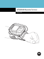
Wired Headset
You can use a mono headset with a microphone for audio communication with an audio enabled application.
The Headset Adapter is required to connect a headset with a standard 2.5 mm jack to the wearable terminal.
NOTE
Symbol recommends 2.5 mm jack headset, p/n 50-11300-050.
Figure 3-12 Typical Headset Connected to Headset Adapter
Refer to the WT4070/90 Integrator Guide for instructions on assembling the headset and Headset Adapter.
The Headset Adapter has a clip for mounting onto the wrist mount or belt.
3 - 12 WT4070/90 Wearable Terminal User Guide
Maintenance & Troubleshooting
Chapter 4
Chapter 4
Chapter 4 Maintenance & Troubleshooting
Introduction
This chapter includes instructions on cleaning and storing the wearable terminal, and provides troubleshooting
solutions for potential problems during wearable terminal operation.
Maintaining the Wearable Terminal
For trouble-free service, observe the following tips when using the wearable terminal:
•
Protect the wearable terminal from temperature extremes.
•
Do not store or use the wearable terminal in any location that is extremely dusty, damp, or wet.
•
Use a soft lens cloth to clean the wearable terminal. If the surface of the wearable terminal screen
becomes soiled, clean it with a soft cloth moistened with a diluted window-cleaning solution.
•
Periodically replace the rechargeable Li-ion battery to ensure maximum battery life and product
performance. Battery life depends on individual usage patterns.
•
Take care not to scratch the screen of the wearable terminal.
•
The screen of the wearable terminal contains glass. Take care not to drop the wearable terminal or
subject it to strong impact.
•
Regularly replace all Velcro® straps on the wrist mount and wearable scanners, to ensure adequate
adhesion of the Velcro.
Wrist Mount Cleaning Istructions
It may be necessary to wash the wrist mount straps and replaceable pad when they become soiled.
Remove the straps and pad from the wrist mount. Hand wash in cold water with a mild detergent (such as
Woolite®). Do not use bleach. Air dry. Do not use a dryer.
Replaceable Pad
Strap
Figure 4-1 Wrist Mount Soft Goods
4-2
WT4070/90 Wearable Terminal User Guide
Troubleshooting
Wearable Terminal
Table 4-1 Troubleshooting the Wearable Terminal
Problem
Wearable terminal
does not turn on.
Cause
Solution
Lithium-ion battery
not charged.
Charge or replace the lithium-ion battery in the wearable
terminal.
Lithium-ion battery
not installed
properly.
Ensure battery is installed properly. See Installing and
Removing the Main Battery on page 1-5.
System crash.
Perform a warm boot. If the wearable terminal still does not
turn on, perform a cold boot. See Resetting the Wearable
Terminal on page 2-14.
Battery failed.
Replace battery. If the wearable terminal still does not operate,
try a warm boot, then a cold boot. See Resetting the Wearable
Terminal on page 2-14.
Wearable terminal
removed from
cradle while battery
was charging.
Insert wearable terminal in cradle and begin charging. The
lithium-ion battery requires less than four hours to recharge
fully.
Ambient
temperature of the
cradle is too warm
or too cold.
Move the cradle to an area where the ambient temperature is
between 0 °C and 40 °C (32 °F and 104 °F).
Cannot see
characters on display.
Wearable terminal
not powered on.
Press the Power button.
During data
communication, no
data was transmitted,
or transmitted data
was incomplete.
Wearable terminal
removed from
cradle or unplugged
from host computer
during
communication.
Replace the wearable terminal in the cradle, or reattach the
Synchronization cable and re-transmit.
Incorrect cable
configuration.
See the System Administrator.
Communication
software was
incorrectly installed
or configured.
Perform setup. Refer to the WT4090 Integrator Guide for
details.
Rechargeable
lithium-ion battery did
not charge.
Ensure that Microsoft ActiveSync 4.1 or greater is installed on
the host computer.
Maintenance & Troubleshooting
4-3
Table 4-1 Troubleshooting the Wearable Terminal (Continued)
Problem
No sound is audible.
Cause
Volume setting is
low or turned off.
Solution
Adjust volume. Change volume settings by selecting Start >
Settings > Control Panel > Volume & Sounds icon > Volume tab.
Move the slider to change the volume level.
Wearable terminal
turns itself off.
A message appears
stating that the
wearable terminal
memory is full.
Wearable terminal
is inactive.
The wearable terminal turns off after a period of inactivity. If the
wearable terminal is running on battery power, this period can
be set to 30 sec., 1, 2, 3, 4, 5 or 6 minutes. If the wearable
terminal is running on external power, this period can be set to
1, 2, 3, 5, 10, 15 and 30 minutes.
Check the power settings by selecting Start > Settings >
Control Panel > Power icon > Power Off tab.
Change the setting if you need a longer delay before the
automatic shutoff feature activates.
Battery is depleted.
Replace the battery.
Battery is not
inserted properly.
Insert the battery properly (see Installing and Removing the
Main Battery on page 1-5).
The wearable
terminal’s battery is
low and it powers
down to protect
memory content.
Recharge the battery.
Too many files
stored on the
wearable terminal.
Delete unused memos and records. You can save these
records on the host computer.
Too many
applications
installed on the
wearable terminal.
If you have installed additional applications on the wearable
terminal, remove them to recover memory.
Select Start > Settings > Control Panel > Remove Programs
icon.
Select the unused program and select Remove.
4-4
WT4070/90 Wearable Terminal User Guide
Table 4-1 Troubleshooting the Wearable Terminal (Continued)
Problem
The wearable
terminal does not
accept scan input.
WLAN connection is
lost when the
wearable terminal is
connected to a host
computer using
ActiveSync.
Cause
Solution
Scanning
application is not
loaded.
Verify that the unit is loaded with a scanning application. See
the System Administrator.
Unreadable bar
code.
Ensure the symbol is not defaced.
Distance between
exit window and bar
code is incorrect.
Ensure wearable terminal is within proper scanning range.
Wearable terminal
is not programmed
for the bar code.
Ensure the wearable terminal is programmed to accept the
type of bar code being scanned.
Wearable terminal
is not programmed
to generate a beep.
If a beep on a good decode is expected and a beep is not
heard, check that the application is set to generate a beep on
good decode.
Battery is low.
If the scanner stops emitting a laser beam when the trigger is
pressed, check the battery level. When the battery is low, the
scanner shuts off before the wearable terminal low battery
condition notification.
Note: If the scanner is still not reading symbols, contact the
distributor or Motorola.
Microsoft security
feature prevents
connection to two
separate networks.
Disconnect from the WLAN network prior to connecting to a
host computer using ActiveSync.
Maintenance & Troubleshooting
4-5
Four Slot Ethernet Cradle
Table 4-2 Troubleshooting the Four Slot Ethernet Cradle
Problem
Cause
Solution
Wearable terminal amber
Charge Status LED does not
light when wearable terminal
inserted.
Cradle is not receiving power.
Ensure the power cable is connected
securely to both the cradle and to AC power.
Wearable terminal is not
correctly seated.
Remove and re-insert the wearable terminal
into the cradle, ensuring it is correctly seated.
Wearable terminal battery is
not charging.
Wearable terminal was
removed from cradle or cradle
was unplugged from AC power
too soon.
Ensure cradle is receiving power. Ensure the
wearable terminal is seated correctly. If the
wearable terminal battery is fully depleted, it
can take up to four hours to fully recharge a
Standard Battery and it can take up to six
hours to fully recharge an Extended Life
Battery.
Battery is faulty.
Verify that other batteries charge properly. If
so, replace the faulty battery.
The wearable terminal is not
fully seated in the cradle.
Remove and re-insert the wearable terminal
into the cradle, ensuring it is correctly seated.
Wearable terminal removed
from cradle during
communication.
Replace wearable terminal in cradle and
retransmit.
Incorrect cable configuration.
See the system administrator or refer to the
WT4090 Integrator Guide.
Ethernet connection error. Link
LED is not lit (see Link LED on
page 3-5).
See the system administrator. Probable
Ethernet connection error.
Ambient temperature of the
cradle is too warm or too cold.
Move the cradle to an area where the
ambient temperature is between 0 °C and 40
°C (32 °F and 104 °F).
During data communication,
no data was transmitted, or
transmitted data was
incomplete.
Wearable terminal’s main
batteries not charging.
4-6
WT4070/90 Wearable Terminal User Guide
Four Slot Spare Battery Charger
Table 4-3 Troubleshooting The Four Slot Spare Battery Charger
Symptom
Batteries not
charging.
Possible Cause
Solution
Battery was removed
from the charger or
charger was unplugged
from AC power too
soon.
Re-insert the battery in the charger or re-connect the charger’s
power supply.
Battery is faulty.
Verify that other batteries charge properly. If so, replace the faulty
battery.
Battery contacts not
connected to charger.
Verify that the battery is oriented properly and firmly seated in the
battery well correctly with the contacts facing down. See Figure
3-3 on page 3-6 for proper battery orientation.
Ambient temperature of
the charger is too warm
or too cold.
Move the charger to an area where the ambient temperature is
between 0 °C and 40 °C (32 °F and 104 °F).
Maintenance & Troubleshooting
4-7
Single Slot USB Cradle
Table 4-4 Troubleshooting the Single Slot USB Cradle
Symptom
Possible Cause
Charge Status
LEDs do not light
when wearable
terminal or spare
battery is
inserted.
Cradle is not receiving
power.
Ensure the power cable is connected securely to both the cradle
and to AC power.
Wearable terminal is
not seated firmly in the
cradle.
Remove and re-insert the wearable terminal into the cradle,
ensuring it is firmly seated.
Spare battery is not
seated firmly in the
cradle.
Remove and re-insert the spare battery into the charging slot,
ensuring it is firmly seated.
Wearable terminal was
removed from cradle or
cradle was unplugged
from AC power too
soon.
Ensure cradle is receiving power. Ensure wearable terminal is
seated correctly. Confirm main battery is charging. If a wearable
terminal battery is fully depleted, it can take up to four hours to
fully recharge a battery (if the wearable terminal is off, and longer
if the wearable terminal is operating).
View battery status by selecting Start > Settings > Control Panel >
Power icon.
Battery is faulty.
Verify that other batteries charge properly. If so, replace the faulty
battery.
The wearable terminal
is not fully seated in
the cradle.
Remove and re-insert the wearable terminal into the cradle,
ensuring it is firmly seated.
Ambient temperature
of the cradle is too
warm or too cold.
Move the cradle to an area where the ambient temperature is
between 0 °C and 40 °C (32 °F and 104 °F).
Battery inserted
incorrectly.
Verify that the battery is oriented properly and firmly seated in the
battery well correctly with the contacts facing down. See Figure
3-3 on page 3-6 for proper battery orientation.
Battery is faulty.
Verify that other batteries charge properly. If so, replace the faulty
battery.
Ambient temperature
of the cradle is too
warm or too cold.
Move the cradle to an area where the ambient temperature is
between 0 °C and 40 °C (32 °F and 104 °F).
Wearable
terminal battery
is not charging.
Spare battery is
not charging.
Solution
4-8
WT4070/90 Wearable Terminal User Guide
Table 4-4 Troubleshooting the Single Slot USB Cradle (Continued)
Symptom
During data
communications,
no data was
transmitted, or
transmitted data
was incomplete.
Cannot
ActiveSync with
Host Computer
Possible Cause
Solution
Wearable terminal
removed from cradle
during
communications.
Replace wearable terminal in cradle and retransmit.
Incorrect cable
configuration.
See the System Administrator.
Communications
software is not
installed or configured
properly.
Perform setup as described in the WT4090 Integrator Guide.
Wrong USB cable
used.
Ensure that the cable has a USB A connector on one end and a
USB mini B connector on the other end.
Host computer not
configured properly.
Ensure that ActiveSync on the host computer is set to allow USB
connections.
The wearable terminal
is not fully seated in
the cradle.
Remove and re-insert the wearable terminal into the cradle,
ensuring it is firmly seated.
Ensure that Microsoft ActiveSync 4.1 or greater is installed on the
host computer.
Specifications
Appendix A
Appendix A Specifications
Technical Specifications
The following tables summarize the wearable terminal’s intended operating environment and general technical
hardware specifications.
Wearable Terminal
The following table summarizes the wearable terminal’s intended operating environment.
Table A-1 Technical Specifications
Item
Description
Physical and Environmental Characteristics
Dimensions
5.7 inches L x 3.7 inches W x 1.0 inch H
(14.2 cm L x 9.3 cm H x 2.6 cm H)
Weight (including battery)
11.3 oz. (320 gm)
Keyboard
Two-color Alphanumeric Keypad or Triple-tap Alphanumeric Keypad
Display
Color 2.8 inch QVGA
Main Battery
Removable, rechargeable 3.7 VDC Lithium Ion battery.
Standard capacity: 2330 mAh
Backup Battery
Two NiMH batteries (rechargeable) 15 mAh 2.4 VDC (not user accessible)
Performance Characteristics
CPU
XScale PXA270 processor at 520 MHz
Operating System
Microsoft Windows CE 5.0 Professional
Memory
Windows CE: 64MB Flash/128MB RAM
Application Development
PSDK, DCP and SMDK available through Symbol Developer Zone web site
Data Capture Options
RS309 scanner
RS409 scanner
User Environment
Operating Temperature
-4 °F to 122°F (-20 °C to 50 °C)
Storage Temperature
-40 °F to 158 °F (-40 °C to 70 °C)
A-2
WT4070/90 Wearable Terminal User Guide
Table A-1 Technical Specifications (Continued)
Item
Description
Battery Charging Temperature
32 °F to 104 °F (0 °C to +40 °C) ambient temperature range.
Humidity
5% to 95% non condensing
Drop Specification
Multiple 4 ft.(1.2 m) drops to concrete across operating temperature range
Tumble
500 half-meter tumbles at room temperature (1,000 drops)
Environmental Sealing
IP54 Category 2
ESD
± 15k VDC air discharge
± 8k VDC direct discharge
± 8k VDC indirect discharge
WLAN Wireless Data Communications
WLAN radio
WT4070: Symbol 802.11b/g
WT4090: Symbol 802.11a/b/g
Operating Channels
Channel 8 - 169 (5040 - 5845 MHz) (4920 - 4980 MHz) Japan only
Channel 1 - 13 (2412 - 2472 MHz)
Channel 14 (2484 MHz) Japan only
Actual operating frequencies depend on regulatory rules and certification
agency
Security
WPA2, WEP (40 or 128 bit), TKIP, TLS, TTLS (MS-CHAP), TTLS (MS-CHAP
v2), TTLS (CHAP), TTLS-MD5, TTLS-PAP, PEAP-TLS, PEAP (MS-CHAP v2),
AES, LEAP
Voice Communication
Runs voice recognition engines and text-to-speech engines for voice picking
applications
Output Power
100 mW U.S. and International
Data Rate
802.11a: up to 54Mb per second
802.11b: up to 11Mb per second
802.11g: up to 54Mb per second
Frequency Range
802.11a: 5 GHz; country-dependent
802.11b: 2.4 GHz; country-dependent
802.11g: 2.4 GHz; country-dependent
Antenna
Internal
WPAN Wireless Data Communications
Bluetooth
Bluetooth Version 1.2
Appendix A: Specifications A - 3
Table A-1 Technical Specifications (Continued)
Item
Description
Peripherals and Accessories
Cradles
Single Slot USB
Four Slot Ethernet
Printers
Supports extensive line of Symbol approved printers, cables and accessories
Charger
Four Slot Battery Charger
Other Accessories
Headset adapter to a 2.5 mm barrel jack headset connector
Regulatory
Electrical Safety
Certified to UL60950-1, CSA C22.2 No. 60950-1, EN60950/IEC 60950-1 plus
all national deviations
EMC
FCC Part 15 Subpart B, ICES-003 Class B, EN 60601-1-2, EN 61000-3-2, EN
61000-3-3, CISPR 22 Class B, CISPR 24
RF
FCC Parts 15.247, 15.407, 15.205, 15.207, 15.209, 15.203, EN 300 32,
EN301 893, RSS-100, RSS-210, ARIB STD-66 & 33, ARIB STD-T70 & 71
RS309 Scanner
Table A-2 RS309 Technical Specifications
Item
Description
Physical and Environmental Characteristics
Dimensions (standard version
without cables attached)
2.7 inch L x 2.4 inch W x 1.5 inch H
(6.8 cm L x 6.1 cm H x 3.8 cm)
Weight (standard version
without cables attached)
3.525 oz. (98 gm)
Current
140 mA typical, 180 mA max
Standby Current
60 µA max
Voltage
3.1 to 3.6 VDC
Vcc Noise Level
200 mV p-p max.
Performance Characteristics
Light Source
650 nm LASER, 1.06 mW
Scan Rate
35 (± 5) scans/sec (bidirectional)
Nominal Working Distance
Density
Code Type
Far (inches)
Far (inches)
Yaw
± 50 degrees from normal
Roll
± 20 degrees from vertical
5 mil
39
7
9.5
7.5 mil
39
9.75
15.25
13 mil
UPC
20.25
27.25
20 mil
39
29.25
42.5
55 mil
39
54.5 (Guaranteed)
84.75 (Typical)
A-4
WT4070/90 Wearable Terminal User Guide
Table A-2 RS309 Technical Specifications (Continued)
Item
Description
Pitch
± 65 degrees from normal
User Environment
Operating Temperature
-22 °F to 122 °F (-30 °C to 50 °C)
Storage Temperature
-40 °F to 140 °F (-40 °C to 60 °C)
Humidity
5% to 95% non condensing
Drop Specification
4 ft.(1.8m) drop to concrete
Environmental Sealing
IP54 sealing
Ambient Light Immunity
Indoor: 450 foot-candles (4,844 lux)
Outdoor: 8,000 foot-candles (86,111 lux)
Regulatory
Electrical Safety
Certified to CSA C22.2 No. 60950-1, EN60950-1, IEC 60950-1
EMI/RFI
FCC Part 15 Class B, ICES-003 Class B, European Union EMC and R&TTE
Directives, Australian AS/NZS 4268
Laser Safety
CDRH Class II, IEC 60825-1 Class 2
Laser Decode Capability
Code 39
Codabar
Interleaved 2 of 5
MSI
UPC/EAN supplementals
Webcode
Code 128
Code 11
EAN-8
UPCA
Coupon Code
Chinese 2 of 5
RS409 Scanner
Table A-3 RS409 Technical Specifications
Item
Description
Physical and Environmental Characteristics
Dimensions
1.9 in. L x 1.4 in. W x 1.9 in. H
(4.8 cm L x 3.6 cm H x 4.8 cm H)
Weight (standard version
without cables attached)
2.0 oz. (56.7 gm)
Current
92 mA typical, 121 mA max
Standby Current
12µA typical/60 µA max
Voltage
3.1 to 3.6 VDC
Vcc Noise Level
100 mV p-p max.
Performance Characteristics
Light Source
650 nm LASER, 1.55 mW
Code 93
Discrete 2 of 5
EAN-13
UPCE
Trioptic 39
RSS
Appendix A: Specifications A - 5
Table A-3 RS409 Technical Specifications (Continued)
Item
Description
Scan Rate
104 (± 12) scans/sec (bidirectional)
Nominal Working
Distance
Density
Code Type
Far (inches)
Far (inches)
Yaw
± 50 degrees from normal
Roll
± 35 degrees from vertical
Pitch
± 65 degrees from normal
5 mil
39
4.75
8.75
7.5 mil
39
8.75
14.25
10 mil 13 mil
39
UPC
13.25 17.25
24.25
20 mil 40 mil
39
39
21.5
22.25
35.75
55 mil
39
27 (Guaranteed)
50.5
(Typical)
User Environment
Operating Temperature
-4 °F to 122 °F (-20 °C to 50 °C)
Storage Temperature
-25 °F to 160 °F (-40 °C to 70 °C)
Humidity
5% to 95% non condensing
Drop Specification
4 ft.(1.8m) drop to concrete
Environmental Sealing
IP54 sealing
Ambient Light Immunity
Indoor: 450 foot-candles (4,844 lux)
Outdoor: 8,000 foot-candles (86,111 lux)
Regulatory
Electrical Safety
Certified to CSA C22.2 No. 60950-1, EN60950-1, IEC 60950-1
EMI/RFI
FCC Part 15 Class B, ICES-003 Class B, European Union EMC and R&TTE
Directives, Australian AS/NZS 4268
Laser Safety
CDRH Class II, IEC 60825-1 Class 2
Laser Decode Capability
Code 39
Codabar
Interleaved 2 of 5
MSI
UPC/EAN supplementals
Webcode
Code 128
Code 11
EAN-8
UPCA
Coupon Code
Chinese 2 of 5
Code 93
Discrete 2 of 5
EAN-13
UPCE
Trioptic 39
RSS
A-6
WT4070/90 Wearable Terminal User Guide
Cradles
Table A-4 Accessory Specifications
Single Slot USB Cradle
Four Slot Ethernet Cradle
Four Slot Spare Battery
Charger
Operating
Temperature
32 °F to 122 °F
(0 °C to +50 °C)
32 °F to 104 °F
(0 °C to +40 °C)
Storage
Temperature
-40 °F to 158 °F
(-40 °C to 70 °C)
Battery
Charging
Temperature
32 °F to 104 °F
(0 °C to +40 °C) ambient temperature
Humidity
5% to 95% non-condensing
Size (L x W x H)
6.6 in. x 5.1 in. x 3.9 in.
(16.8 cm x 13.0 cm x 9.9 cm)
6.7 in. x 18.9 in. x 4.5 in.
(17.0 cm x 48.1 cm x 11.4 cm)
8.5 in. x 5.7 in. x 1.9 in.
(21.5 cm x 14.5 cm x 4.9 cm)
Weight
12.1 oz. (344 gm)
45.9 oz. (1300 gm)
15.3 oz. (435 gm)
Power Supply
12 VDC, 3.3 A
12 VDC, 9 A
12 VDC, 3.3 A
Drop
30 inches (76.2 cm) to vinyl covered concrete
Electrostatic
Discharge
(ESD)
±15 kV air discharge, ± 8 kV contact discharge
Typical Power
20 W
60 W
25 W
Regulatory
Appendix B
Appendix B
Regulatory
Introduction
This appendix contains the accessory power supply regulatory compliance statements.
Accessory Power Supply Regulatory Compliance
Table B-1 Accessory Power Supplies, Regulatory Compliance Statements
Accessory
Power Supplies Regulatory Compliance Statements
Single Slot USB Cradle Power
Supply
Four Slot Battery Charger Power
Supply
Use only a Symbol-approved power supply output rated 12 VDC and
minimum 3.3 A. The power supply is certified to EN60950 with SELV
outputs. Use of alternative power supply will invalidate any approval given
to this device and may be dangerous.
Benutzen Sie nur eine von Symbol Technologies genehmigte
Stromversorgung mit einer Ausgangsleistung von 12 V (Gleichstrom) und
mindestens 3.3 A. Die Stromversorgung ist nach EN60950 für die
Verwendung in SELV-Stromkreisen zertifiziert. Bei Verwendung eines
anderen Netzteils werden alle für das Gerät gewährten Genehmigungen
außer Kraft gesetzt, und der Betrieb kann gefährlich sein.
Four Slot Ethernet Cradle Power
Supply
Use only a Symbol-approved power supply output rated 12 VDC and
minimum 9 A. The power supply is certified to EN60950 with SELV outputs.
Use of alternative power supply will invalidate any approval given to this
device and may be dangerous.
Benutzen Sie nur eine von Symbol Technologies genehmigte
Stromversorgung mit einer Ausgangsleistung von 12 V (Gleichstrom) und
mindestens 9 A. Die Stromversorgung ist nach EN60950 für die
Verwendung in SELV-Stromkreisen zertifiziert. Bei Verwendung eines
anderen Netzteils werden alle für das Gerät gewährten Genehmigungen
außer Kraft gesetzt, und der Betrieb kann gefährlich sein.
B-2
WT4070/90 Wearable Terminal User Guide
Glossary
GlossaryGlossary
A
API. An interface by means of which one software component communicates with or controls another. Usually
used to refer to services provided by one software component to another, usually via software interrupts or
function calls
Application Programming Interface. See API.
ANSI Terminal. A display terminal that follows commands in the ANSI standard terminal language. For
example, it uses escape sequences to control the cursor, clear the screen and set colors. Communications
programs support the ANSI terminal mode and often default to this terminal emulation for dial-up
connections to online services.
ASCII. American Standard Code for Information Interchange. A 7 bit-plus-parity code representing 128 letters,
numerals, punctuation marks and control characters. It is a standard data transmission code in the U.S.
B
Bar. The dark element in a printed bar code symbol.
Bar Code. A pattern of variable-width bars and spaces which represents numeric or alphanumeric data in
machine-readable form. The general format of a bar code symbol consists of a leading margin, start
character, data or message character, check character (if any), stop character, and trailing margin. Within
this framework, each recognizable symbology uses its own unique format. See Symbology.
Bit. Binary digit. One bit is the basic unit of binary information. Generally, eight consecutive bits compose one
byte of data. The pattern of 0 and 1 values within the byte determines its meaning.
Bits per Second (bps). Bits transmitted or received.
Bit. Binary digit. One bit is the basic unit of binary information. Generally, eight consecutive bits compose one
byte of data. The pattern of 0 and 1 values within the byte determines its meaning.
bps. See Bits Per Second.
Glossary - 2
WT4070/90 Wearable Terminal User Guide
Byte. On an addressable boundary, eight adjacent binary digits (0 and 1) combined in a pattern to represent a
specific character or numeric value. Bits are numbered from the right, 0 through 7, with bit 0 the low-order
bit. One byte in memory is used to store one ASCII character.
boot or boot-up. The process a computer goes through when it starts. During boot-up, the computer can run
self-diagnostic tests and configure hardware and software.
C
CDRH. Center for Devices and Radiological Health. A federal agency responsible for regulating laser product
safety. This agency specifies various laser operation classes based on power output during operation.
CDRH Class 1. This is the lowest power CDRH laser classification. This class is considered intrinsically safe,
even if all laser output were directed into the eye's pupil. There are no special operating procedures for this
class.
CDRH Class 2. No additional software mechanisms are needed to conform to this limit. Laser operation in this
class poses no danger for unintentional direct human exposure.
Character. A pattern of bars and spaces which either directly represents data or indicates a control function,
such as a number, letter, punctuation mark, or communications control contained in a message.
Codabar. A discrete self-checking code with a character set consisting of digits 0 to 9 and six additional
characters: (-$:/,+).
Code 128. A high density symbology which allows the controller to encode all 128 ASCII characters without
adding extra symbol elements.
Code 3 of 9 (Code 39). A versatile and widely used alphanumeric bar code symbology with a set of 43
character types, including all uppercase letters, numerals from 0 to 9 and 7 special characters (space, minus
(-), plus (+), period (.), dollar sign ($), slash (/), and percent (%)). The code name is derived from the fact
that 3 of 9 elements representing a character are wide, while the remaining 6 are narrow.
Code 93. An industrial symbology compatible with Code 39 but offering a full character ASCII set and a higher
coding density than Code 39.
Cold Boot. A cold boot restarts the wearable terminal and erases all user stored records and entries.
COM port. Communication port; ports are identified by number, e.g., COM1, COM2.
Cradle. A cradle is used for charging the terminal battery and for communicating with a host computer, and
provides a storage place for the terminal when not in use.
D
DCP. See Device Configuration Package.
Glossary - 3
Decode. To recognize a bar code symbology (e.g., UPC/EAN) and then analyze the content of the specific bar
code scanned.
Decode Algorithm. A decoding scheme that converts pulse widths into data representation of the letters or
numbers encoded within a bar code symbol.
Decryption. Decryption is the decoding and unscrambling of received encrypted data. Also see, Encryption
and Key.
Depth of Field. The range between minimum and maximum distances at which a scanner can read a symbol
with a certain minimum element width.
Device Configuration Package. The Symbol Device Configuration Package provides the Product Reference
Guide (PRG), flash partitions, Terminal Configuration Manager (TCM) and the associated TCM scripts. With
this package hex images that represent flash partitions can be created and downloaded to the wearable
terminal.
Discrete 2 of 5. A binary bar code symbology representing each character by a group of five bars, two of which
are wide. The location of wide bars in the group determines which character is encoded; spaces are
insignificant. Only numeric characters (0 to 9) and START/STOP characters may be encoded.
E
EAN. European Article Number. This European/International version of the UPC provides its own coding format
and symbology standards. Element dimensions are specified metrically. EAN is used primarily in retail.
ENQ (RS-232). ENQ software handshaking is also supported for the data sent to the host.
ESD. Electro-Static Discharge
F
Flash Disk. An additional megabyte of non-volatile memory for storing application and configuration files.
Flash Memory. Flash memory is nonvolatile, semi-permanent storage that can be electronically erased in the
circuit and reprogrammed. Wearable terminals use Flash memory to store the operating system
(ROM-DOS), the terminal emulators, and the Citrix ICA Client for DOS.
File Transfer Protocol (FTP). A TCP/IP application protocol governing file transfer via network or telephone
lines. See TCP/IP.
FTP. See File Transfer Protocol.
Flash Memory. Flash memory is responsible for storing the system firmware and is non-volatile. If the system
power is interrupted the data is not be lost.
Glossary - 4
WT4070/90 Wearable Terminal User Guide
H
Hard Reset. See Cold Boot.
Hz. Hertz; A unit of frequency equal to one cycle per second.
Host Computer. A computer that serves other terminals in a network, providing such services as computation,
database access, supervisory programs and network control.
I
IEC. International Electrotechnical Commission. This international agency regulates laser safety by specifying
various laser operation classes based on power output during operation.
IEC (825) Class 1. This is the lowest power IEC laser classification. Conformity is ensured through a software
restriction of 120 seconds of laser operation within any 1000 second window and an automatic laser
shutdown if the scanner's oscillating mirror fails.
IEEE Address. See MAC Address.
Interleaved 2 of 5. A binary bar code symbology representing character pairs in groups of five bars and five
interleaved spaces. Interleaving provides for greater information density. The location of wide elements
(bar/spaces) within each group determines which characters are encoded. This continuous code type
uses no intercharacter spaces. Only numeric (0 to 9) and START/STOP characters may be encoded.
IOCTL. Input/Output Control.
Interleaved Bar Code. A bar code in which characters are paired together, using bars to represent the first
character and the intervening spaces to represent the second.
Interleaved 2 of 5. A binary bar code symbology representing character pairs in groups of five bars and five
interleaved spaces. Interleaving provides for greater information density. The location of wide elements
(bar/spaces) within each group determines which characters are encoded. This continuous code type uses
no intercharacter spaces. Only numeric (0 to 9) and START/STOP characters may be encoded.
Internet Protocol Address. See IP.
I/O Ports. interface The connection between two devices, defined by common physical characteristics, signal
characteristics, and signal meanings. Types of interfaces include RS-232 and PCMCIA.
Input/Output Ports. I/O ports are primarily dedicated to passing information into or out of the terminal’s
memory. Wearable terminals include Serial and USB ports.
IP. Internet Protocol. The IP part of the TCP/IP communications protocol. IP implements the network layer (layer
3) of the protocol, which contains a network address and is used to route a message to a different network
or subnetwork. IP accepts “packets” from the layer 4 transport protocol (TCP or UDP), adds its own header
to it and delivers a “datagram” to the layer 2 data link protocol. It may also break the packet into fragments
to support the maximum transmission unit (MTU) of the network.
Glossary - 5
IP Address. (Internet Protocol address) The address of a computer attached to an IP network. Every client and
server station must have a unique IP address. A 32-bit address used by a computer on a IP network. Client
workstations have either a permanent address or one that is dynamically assigned to them each session.
IP addresses are written as four sets of numbers separated by periods; for example, 204.171.64.2.
IPX/SPX. Internet Package Exchange/Sequential Packet Exchange. A communications protocol for Novell. IPX
is Novell’s Layer 3 protocol, similar to XNS and IP, and used in NetWare networks. SPX is Novell's version
of the Xerox SPP protocol.
IS-95. Interim Standard 95. The EIA/TIA standard that governs the operation of CDMA cellular service. Versions
include IS-95A and IS-95B. See CDMA.
K
Key. A key is the specific code used by the algorithm to encrypt or decrypt the data. Also see, Encryption and
Decrypting.
L
laser scanner. A type of bar code reader that uses a beam of laser light.
LASER. Light Amplification by Stimulated Emission of Radiation.The laser is an intense light source. Light from
a laser is all the same frequency, unlike the output of an incandescent bulb. Laser light is typically coherent
and has a high energy density.
LCD. See Liquid Crystal Display.
LED Indicator. A semiconductor diode (LED - Light Emitting Diode) used as an indicator, often in digital
displays. The semiconductor uses applied voltage to produce light of a certain frequency determined by the
semiconductor's particular chemical composition.
Liquid Crystal Display (LCD). A display that uses liquid crystal sealed between two glass plates. The crystals
are excited by precise electrical charges, causing them to reflect light outside according to their bias. They
use little electricity and react relatively quickly. They require external light to reflect their information to the
user.
Light Emitting Diode. See LED.
M
MDN. Mobile Directory Number. The directory listing telephone number that is dialed (generally using POTS) to
reach a mobile unit. The MDN is usually associated with a MIN in a cellular telephone -- in the US and
Canada, the MDN and MIN are the same value for voice cellular users. International roaming considerations
often result in the MDN being different from the MIN.
Glossary - 6
WT4070/90 Wearable Terminal User Guide
MIL. 1 mil = 1 thousandth of an inch.
MIN. Mobile Identification Number. The unique account number associated with a cellular device. It is broadcast
by the cellular device when accessing the cellular system.
N
Nominal. The exact (or ideal) intended value for a specified parameter. Tolerances are specified as positive
and negative deviations from this value.
O
Open Data-Link Interface (ODI). Novell’s driver specification for an interface between network hardware and
higher-level protocols. It supports multiple protocols on a single NIC (Network Interface Controller). It is
capable of understanding and translating any network information or request sent by any other
ODI-compatible protocol into something a NetWare client can understand and process.
Open System Authentication. Open System authentication is a null authentication algorithm.
P
PAN . Personal area network. Using Bluetooth wireless technology, PANs enable devices to communicate
wirelessly. Generally, a wireless PAN consists of a dynamic group of less than 255 devices that
communicate within about a 33-foot range. Only devices within this limited area typically participate in the
network.
Parameter. A variable that can have different values assigned to it.
PING. (Packet Internet Groper) An Internet utility used to determine whether a particular IP address is online. It
is used to test and debug a network by sending out a packet and waiting for a response.
Print Contrast Signal (PCS). Measurement of the contrast (brightness difference) between the bars and
spaces of a symbol. A minimum PCS value is needed for a bar code symbol to be scannable. PCS = (RL RD) / RL, where RL is the reflectance factor of the background and RD the reflectance factor of the dark
bars.
Q
QWERTY. A standard keyboard commonly used on North American and some European PC keyboards.
“QWERTY” refers to the arrangement of keys on the left side of the third row of keys.
Glossary - 7
R
RAM. Random Access Memory. Data in RAM can be accessed in random order, and quickly written and read.
Resolution. The narrowest element dimension which is distinguished by a particular reading device or printed
with a particular device or method.
RF. Radio Frequency.
ROM. Read-Only Memory. Data stored in ROM cannot be changed or removed.
Router. A device that connects networks and supports the required protocols for packet filtering. Routers are
typically used to extend the range of cabling and to organize the topology of a network into subnets. See
Subnet.
RS-232. An Electronic Industries Association (EIA) standard that defines the connector, connector pins, and
signals used to transfer data serially from one device to another.
S
Scan Area. Area intended to contain a symbol.
Scanner. An electronic device used to scan bar code symbols and produce a digitized pattern that corresponds
to the bars and spaces of the symbol. Its three main components are:
1. Light source (laser or photoelectric cell) - illuminates a bar code.
2. Photodetector - registers the difference in reflected light (more light reflected from spaces).
3. Signal conditioning circuit - transforms optical detector output into a digitized bar pattern.
SDK. Software Development Kit
Secure Sockets Layer (SSL). SSL is a commonly-used protocol for managing the security of a message
transmission on the Internet. SSL uses a program layer located between the Internet's Hypertext Transfer
Protocol (HTTP) and Transport Control Protocol (TCP) layers. SSL is included as part of both the Microsoft
and Netscape browsers and most Web server products. Developed by Netscape, SSL also gained the
support of Microsoft and other Internet client/server developers as well and became the de facto standard
until evolving into Transport Layer Security. The “sockets” part of the term refers to the sockets method of
passing data back and forth between a client and a server program in a network or between program layers
in the same computer. SSL uses the public-and-private key encryption system from RSA, which also
includes the use of a digital certificate.
Shared Key. Shared Key authentication is an algorithm where both the AP and the MU share an authentication
key.
SID. System Identification code. An identifier issued by the FCC for each market. It is also broadcast by the
cellular carriers to allow cellular devices to distinguish between the home and roaming service.
SMDK. Symbol Mobility Developer’s Kit.
Soft Reset. See Warm Boot.
Glossary - 8
WT4070/90 Wearable Terminal User Guide
Subnet. A subset of nodes on a network that are serviced by the same router. See Router.
Subnet Mask. A 32-bit number used to separate the network and host sections of an IP address. A custom
subnet mask subdivides an IP network into smaller subsections. The mask is a binary pattern that is
matched up with the IP address to turn part of the host ID address field into a field for subnets. Default is
often 255.255.255.0.
Substrate. A foundation material on which a substance or image is placed.
Symbol. A scannable unit that encodes data within the conventions of a certain symbology, usually including
start/stop characters, quiet zones, data characters and check characters.
Symbology. The structural rules and conventions for representing data within a particular bar code type (e.g.
UPC/EAN, Code 39, PDF417, etc.).
T
TCP/IP. (Transmission Control Protocol/Internet Protocol) A communications protocol used to internetwork
dissimilar systems. This standard is the protocol of the Internet and has become the global standard for
communications. TCP provides transport functions, which ensures that the total amount of bytes sent is
received correctly at the other end. UDP is an alternate transport that does not guarantee delivery. It is
widely used for real-time voice and video transmissions where erroneous packets are not retransmitted. IP
provides the routing mechanism. TCP/IP is a routable protocol, which means that all messages contain not
only the address of the destination station, but the address of a destination network. This allows TCP/IP
messages to be sent to multiple networks within an organization or around the world, hence its use in the
worldwide Internet. Every client and server in a TCP/IP network requires an IP address, which is either
permanently assigned or dynamically assigned at startup.
Telnet. A terminal emulation protocol commonly used on the Internet and TCP/IP-based networks. It allows a
user at a terminal or computer to log onto a remote device and run a program.
Terminal. See Wearable Terminal.
Terminal Emulation. A “terminal emulation” emulates a character-based mainframe session on a remote
non-mainframe terminal, including all display features, commands and function keys. The WT4090 Series
supports Terminal Emulations in 3270, 5250 and VT220.
TFTP. (Trivial File Transfer Protocol) A version of the TCP/IP FTP (File Transfer Protocol) protocol that has no
directory or password capability. It is the protocol used for upgrading firmware, downloading software and
remote booting of diskless devices.
Tolerance. Allowable deviation from the nominal bar or space width.
Transmission Control Protocol/Internet Protocol. See TCP/IP.
Transport Layer Security (TLS). TLS is a protocol that ensures privacy between communicating applications
and their users on the Internet. When a server and client communicate, TLS ensures that no third party may
eavesdrop or tamper with any message. TLS is the successor to the Secure Sockets Layer (SSL).
Trivial File Transfer Protocol. See TFTP.
Glossary - 9
U
UPC. Universal Product Code. A relatively complex numeric symbology. Each character consists of two bars
and two spaces, each of which is any of four widths. The standard symbology for retail food packages in the
United States.
UDP. User Datagram Protocol. A protocol within the IP protocol suite that is used in place of TCP when a reliable
delivery is not required. For example, UDP is used for real-time audio and video traffic where lost packets
are simply ignored, because there is no time to retransmit. If UDP is used and a reliable delivery is required,
packet sequence checking and error notification must be written into the applications.
U
Visible Laser Diode (VLD). A solid state device which produces visible laser light.
W
Warm Boot. A warm boot restarts the wearable terminal by closing all running programs. All data that is not
saved to flash memory is lost.
Wearable Terminal. In this text, wearable terminal refers to the Symbol WT4090 that can be set up to
communicate with a network, using wireless radio technology.
Glossary - 10 WT4070/90 Wearable Terminal User Guide
Index
IndexIndex
Numerics
1-D bar codes . . . . . . . . . . . . . . . . . . . . . . . . . . . . . 2-16
28-key keypad . . . . . . . . . . . . . . . . . . . . . . . . . . . . . . 2-5
warm . . . . . . . . . . . . . . . . . . . . . . . . . . . . . 2-1, 2-14
bullets . . . . . . . . . . . . . . . . . . . . . . . . . . . . . . . . . . . . .viii
buttons
power . . . . . . . . . . . . . . . . . . . . . . . . . . . . . . . . . . 2-1
A
C
accessories . . . . . . . . . . . . . . . . . . . . . . . . . . . . . . . . 1-3
four slot charge only cradle . . . . . . . . . . . . . . . . 3-1
four slot cradles
battery charging . . . . . . . . . . . . . . . . . . . . . . 3-5
four slot Ethernet cradle . . . . . . . . . . . . . . . . . . . 3-4
LED indicators . . . . . . . . . . . . . . . . . . . . . . . 3-5
four slot Ethernet/USB cradle . . . . . . . . . . . . 1-3, 3-1
four slot spare battery charger . . . . . . . . . . . . . . 1-3
serial/USB cradle . . . . . . . . . . . . . . . . . . . . . 1-3, 3-1
single slot serial/USB cradle . . . . . . . . . . . . . . . . 3-2
LED indicators . . . . . . . . . . . . . . . . . . . . 3-3, 3-6
SMDK . . . . . . . . . . . . . . . . . . . . . . . . . . . . . . . . . 1-3
spare battery charger . . . . . . . . . . . . . . . . . . . . . 3-6
power connection . . . . . . . . . . . . . . . . . . . . . 3-6
characters, special . . . . . . . . . . . . . . . . . . . . . . . . . . . 2-6
charging
spare batteries . . . . . . . . . . . . . . . . . . . . . . . . . . . 1-7
temperature range . . . . . . . . . . . . . . . . . . . . . . . . A-6
charging batteries . . . . . . . . . . . . . . . . . . . . . . . . . . . 1-6
charging spare batteries . . . . . . . . . . . . . . . . . . . . . . 1-7
cleaning . . . . . . . . . . . . . . . . . . . . . . . . . . . . . . . . . . . 4-1
cold boot . . . . . . . . . . . . . . . . . . . . 1-10, 2-1, 2-14, 2-15
configuration . . . . . . . . . . . . . . . . . . . . . . . . . . . . . . . . vi
configurations . . . . . . . . . . . . . . . . . . . . . . . . . . . . . . . vi
conventions
notational . . . . . . . . . . . . . . . . . . . . . . . . . . . . . . . .viii
CPU . . . . . . . . . . . . . . . . . . . . . . . . . . . . . . . . . . . . . . A-1
cradles
four slot charge only . . . . . . . . . . . . . . . . . . . . . . 3-1
four slot cradles
battery charging . . . . . . . . . . . . . . . . . . . . . . 3-5
four slot Ethernet . . . . . . . . . . . . . . . . . . . . . . . . . 3-4
four slot Ethernet cradle
LED indicators . . . . . . . . . . . . . . . . . . . . . . . . 3-5
four slot Ethernet/USB . . . . . . . . . . . . . . . . . 1-3, 3-1
serial/USB . . . . . . . . . . . . . . . . . . . . . . . . . . 1-3, 3-1
single slot . . . . . . . . . . . . . . . . . . . . . . . . . . . . . . 3-2
LED indicators . . . . . . . . . . . . . . . . . . . . 3-3, 3-6
spare battery charger . . . . . . . . . . . . . . . . . . . . . 3-6
power connection . . . . . . . . . . . . . . . . . . . . . 3-6
current time . . . . . . . . . . . . . . . . . . . . . . . . . . . . . . . 2-10
B
backup battery . . . . . . . . . . . . . . . . . . . . . . . . . . . . 2-11
charging . . . . . . . . . . . . . . . . . . . . . . . . . . . . . . . 1-6
bar codes
one dimensional . . . . . . . . . . . . . . . . . . . . . . . . 2-16
battery
backup charging . . . . . . . . . . . . . . . . . . . . . . . . . 1-6
charging . . . . . . . . . . . . . . . . . . . . . . . . . . . . . . . 1-6
temperature range . . . . . . . . . . . . . . . . . . . . A-6
installing . . . . . . . . . . . . . . . . . . . . . . . . . . . . . . . 1-5
removing . . . . . . . . . . . . . . . . . . . . . . . . . . . . . . . 1-7
battery charging
four slot cradles . . . . . . . . . . . . . . . . . . . . . . . . . 3-5
battery charging temperature . . . . . . . . . . . . . . . . . . A-2
battery icon . . . . . . . . . . . . . . . . . . . . . . . . . . . . . . . 2-10
battery status . . . . . . . . . . . . . . . . . . . . . . . . . . . . . 2-11
boot
cold . . . . . . . . . . . . . . . . . . . . . .1-10, 2-1, 2-14, 2-15
D
data capture . . . . . . . . . . . . . . . . . . . . . . . . . . . . . vi, 2-16
adjusting the distance . . . . . . . . . . . . . . . . . . . . 2-17
indicator . . . . . . . . . . . . . . . . . . . . . . . . . . . . . . . 2-17
Index - 2
WT4070/90 Wearable Terminal User Guide
laser scanning . . . . . . . . . . . . . . . . . . . . . . . . . . 2-16
one dimensional bar codes . . . . . . . . . . . . . . . . 2-16
scan angle . . . . . . . . . . . . . . . . . . . . . . . . . . . . . 2-16
scan range . . . . . . . . . . . . . . . . . . . . . . . . . . . . 2-16
scanning . . . . . . . . . . . . . . . . . . . . . . . . . . . . . . 2-16
date/time . . . . . . . . . . . . . . . . . . . . . . . . . . . . . . . . . 2-10
DCP for WT4090c50 . . . . . . . . . . . . . . . . . . . . . . . . . . .ix
Device Configuration Package . . . . . . . . . . . . . . . . . 1-3
Device Configuration Package for WT4090c50 . . . . . . .ix
dimensions . . . . . . . . . . . . . . . . . . . . . . . . A-1, A-3, A-4
display . . . . . . . . . . . . . . . . . . . . . . . . . . . . . . . . . . vi, A-1
drop specification . . . . . . . . . . . . . . . . . . . . A-2, A-4, A-5
E
two-color alphanumeric . . . . . . . . . . . . . . . . 2-4, 2-5
keyboard . . . . . . . . . . . . . . . . . . . . . . . . . . . . . . . . . . .A-1
keypads . . . . . . . . . . . . . . . . . . . . . . . . . . . . . . . . . . . . vi
28-key . . . . . . . . . . . . . . . . . . . . . . . . . . . . . . . . . 2-5
double-tap . . . . . . . . . . . . . . . . . . . . . . . . . . . . . . 2-3
types . . . . . . . . . . . . . . . . . . . . . . . . . . . . . . . . . . 2-3
L
laser safety . . . . . . . . . . . . . . . . . . . . . . . . . . . . . A-4, A-5
laser scanning
See data capture . . . . . . . . . . . . . . . . . . . . . . . . 2-16
LED . . . . . . . . . . . . . . . . . . . . . . . . . . . . . . . . . . . . . . 2-2
lithium-ion battery . . . . . . . . . . . . . . . . . . . . . . . . . . . . 1-2
electrical safety . . . . . . . . . . . . . . . . . . . . . A-3, A-4, A-5
M
F
main battery
charging . . . . . . . . . . . . . . . . . . . . . . . . . . . . 1-5, 1-6
temperature range . . . . . . . . . . . . . . . . . . . . .A-6
installing . . . . . . . . . . . . . . . . . . . . . . . . . . . . . . . . 1-5
maintenance . . . . . . . . . . . . . . . . . . . . . . . . . . . . . . . . 4-1
memory . . . . . . . . . . . . . . . . . . . . . . . . . . . . . . . . vi, A-1
four slot charge only . . . . . . . . . . . . . . . . . . . . . . . . . 3-1
four slot cradles
battery charging . . . . . . . . . . . . . . . . . . . . . . . . . 3-5
four slot Ethernet cradle . . . . . . . . . . . . . . . . . . . . . . 3-4
LED indicators . . . . . . . . . . . . . . . . . . . . . . . . . . . 3-5
four slot Ethernet/USB . . . . . . . . . . . . . . . . . . . . .1-3, 3-1
four slot spare battery charger . . . . . . . . . . . . . . . . . . 1-3
G
O
operating environment, wearable terminal . . . . . . . . .A-1
operating system . . . . . . . . . . . . . . . . . . . . . . . . . vi, A-1
operating temperature . . . . . . . . . . . . . . . . A-1, A-4, A-5
getting started . . . . . . . . . . . . . . . . . . . . . . . . . . . . . . 1-5
H
hard reset . . . . . . . . . . . . . . . . . . . 1-10, 2-1, 2-14, 2-15
humidity . . . . . . . . . . . . . . . . . . . . . . . . . . . A-2, A-4, A-5
I
icon
battery status . . . . . . . . . . . . . . . . . . . . . . . . . . 2-11
icons
alpha mode . . . . . . . . . . . . . . . . . . . . . . . . . . . . 2-11
ALT . . . . . . . . . . . . . . . . . . . . . . . . . . . . . . . . . . 2-11
CTRL . . . . . . . . . . . . . . . . . . . . . . . . . . . . . . . . . 2-11
function . . . . . . . . . . . . . . . . . . . . . . . . . . . . . . . 2-11
shift . . . . . . . . . . . . . . . . . . . . . . . . . . . . . . . . . . 2-11
information, service . . . . . . . . . . . . . . . . . . . . . . . . . . . .ix
installing main battery . . . . . . . . . . . . . . . . . . . . . . . . 1-5
K
key descriptions
P
parts of the wearable terminal . . . . . . . . . . . . . . 1-1, 1-4
power . . . . . . . . . . . . . . . . . . . . . . . . . . . . . . . . . . . . . 2-2
power button . . . . . . . . . . . . . . . . . . . . . . . . . . . . . . . . 2-1
power LED . . . . . . . . . . . . . . . . . . . . . . . . . . . . . . . . . 2-2
power supply regulatory compliance . . . . . . . . . . . . .B-1
R
radios . . . . . . . . . . . . . . . . . . . . . . . . . . . . . . . . . . . . . . vi
regulatory compliance, power supply . . . . . . . . . . . . .B-1
related documents . . . . . . . . . . . . . . . . . . . . . . . . . . . viii
related software . . . . . . . . . . . . . . . . . . . . . . . . . . . . . viii
removing main battery . . . . . . . . . . . . . . . . . . . . . . . . 1-7
reset
hard . . . . . . . . . . . . . . . . . . . . . 1-10, 2-1, 2-14, 2-15
soft . . . . . . . . . . . . . . . . . . . . . . . . . . . . . . . 2-1, 2-14
resetting . . . . . . . . . . . . . . . . . . . . . . . . . . . . . . . . . . 2-14
Index - 3
S
W
scan status . . . . . . . . . . . . . . . . . . . . . . . . . . . . . . . 2-17
scan status See also data capture
scanning
bar codes . . . . . . . . . . . . . . . . . . . . . . . . . . . . . 2-16
LED indicators . . . . . . . . . . . . . . . . . . . . . . . . . 2-17
See data capture . . . . . . . . . . . . . . . . . . . . . . . 2-16
screen
Symbol splash screen . . . . . . . . . . . . . . . . . . . 1-10
serial/USB cradle . . . . . . . . . . . . . . . . . . . . . . . . 1-3, 3-1
service information . . . . . . . . . . . . . . . . . . . . . . . . . . . . ix
single slot serial/USB cradle . . . . . . . . . . . . . . . . . . . 3-2
LED indicators . . . . . . . . . . . . . . . . . . . . . . . 3-3, 3-6
SMDK for eVC4 . . . . . . . . . . . . . . . . . . . . . . . . . . . . . . ix
soft reset . . . . . . . . . . . . . . . . . . . . . . . . . . . . . . 2-1, 2-14
spare batteries
charging . . . . . . . . . . . . . . . . . . . . . . . . . . . . . . . 1-7
spare battery
charging . . . . . . . . . . . . . . . . . . . . . . . . . . . . . . . 1-7
spare battery charger . . . . . . . . . . . . . . . . . . . . . . . . 3-6
power connection . . . . . . . . . . . . . . . . . . . . . . . . 3-6
special characters . . . . . . . . . . . . . . . . . . . . . . . . . . . 2-6
specifications . . . . . . . . . . . . . . . . . . . . . . . . . . . . . . A-1
starting the wearable terminal . . . . . . . . . . . . . . 1-5, 1-10
status . . . . . . . . . . . . . . . . . . . . . . . . . . . . . . . . . . . 2-10
status icon . . . . . . . . . . . . . . . . . . . . . . . . . . . . 2-10, 2-11
status icons
Windows CE 5.0 . . . . . . . . . . . . . . . . . . . . . . . . 2-10
storage temperature . . . . . . . . . . . . . . . . . .A-1, A-4, A-5
suspend . . . . . . . . . . . . . . . . . . . . . . . . . . . . . . . 1-7, 2-1
Symbol Mobility Developer Kit
See SMDK . . . . . . . . . . . . . . . . . . . . . . . . . . . . . 1-3
Symbol Mobility Developer Kit for eVC4 . . . . . . . . . . . . ix
warm boot . . . . . . . . . . . . . . . . . . . . . . . . . . . . 2-1, 2-14
wearable terminal
power on . . . . . . . . . . . . . . . . . . . . . . . . . . . . . . . 2-1
starting . . . . . . . . . . . . . . . . . . . . . . . . . . . . . . . . 1-10
weight . . . . . . . . . . . . . . . . . . . . . . . . . . . . A-1, A-3, A-4
wireless status icon . . . . . . . . . . . . . . . . . . . . . . . . . 2-11
WLAN 802.11a/b/g . . . . . . . . . . . . . . . . . . . . . . . . . . . vi
WLAN status . . . . . . . . . . . . . . . . . . . . . . . . . . . . . . 2-11
WPAN Bluetooth . . . . . . . . . . . . . . . . . . . . . . . . . . . . . vi
T
taskbar . . . . . . . . . . . . . . . . . . . . . . . . . . . . . . . . . . 2-10
technical specifications, wearable terminal . . . . . . . . A-1
temperature
battery charging . . . . . . . . . . . . . . . . . . . . . . . . . A-6
terminal
charging . . . . . . . . . . . . . . . . . . . . . . . . . . . . . . 2-10
terminal charging . . . . . . . . . . . . . . . . . . . . . . . . . . 2-10
troubleshooting . . . . . . . . . . . . . . . . . . . . . . . . . . . . . 4-2
four slot spare battery charger . . . . . . . . . . . . . . 4-6
single slot serial/USB cradle . . . . . . . . . . . . . . . . 4-7
wearable terminal . . . . . . . . . . . . . . . . . . . . . . . . 4-2
U
unpacking . . . . . . . . . . . . . . . . . . . . . . . . . . . . . . . . . 1-2
Index - 4
WT4070/90 Wearable Terminal User Guide
Motorola, Inc.
One Symbol Plaza
Holtsville, New York 11742-1300
http://www.symbol.com
72E-87633-02
Revision A - February 2007


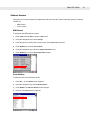


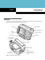
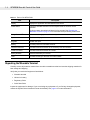
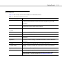
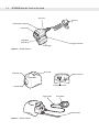
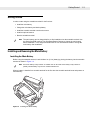
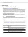
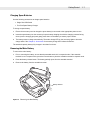
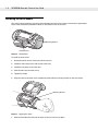
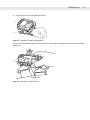
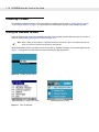
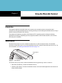
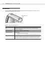
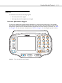

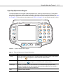
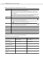
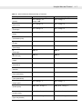
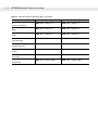
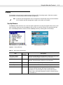
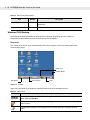


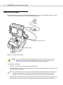
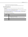
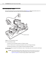
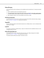
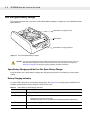
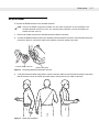


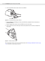
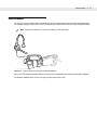

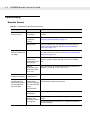
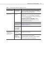
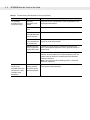

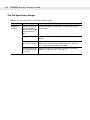
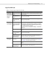


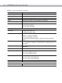
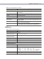
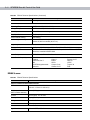

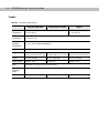
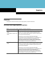


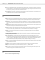
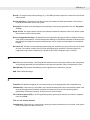
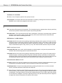
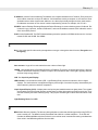
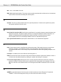
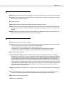
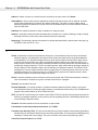
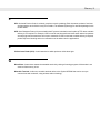


![WT4070/90 Wearable Terminal User Guide [English] (P/N](http://vs1.manualzilla.com/store/data/006889633_1-f70d50700bab93ce466c8ab7dc56daf1-150x150.png)
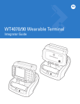
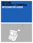
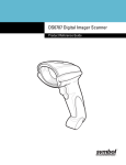
![MC909X User Guide [English] (P/N 72E-72215](http://vs1.manualzilla.com/store/data/006923233_1-b8645820a9c9206bed43f7013f7b5dae-150x150.png)