1
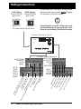
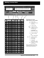
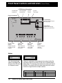
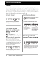
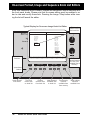
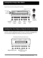
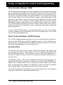
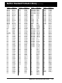
®
Model 801 Series
Quick Start Guide
Index
Page
AC Power
Requirements
2
Connecting a Display
to the Generator
2
Normal Front Panel
Operation
4
Restoring Default
Operation
6
Setting Digital Video
Mode
6
Detailed Status Mode
6
Special Serial Port
Modes
7
Enabling On- Screen
Editing
6
Changing GPIB
Address
7
Cloning Generators
7
Self Calibration
7
Format, Image &
Sequence Knob List
Editors
8
Format Editor
9
Custom Image
Editor
10
Sequence
Editor
11
Sequence Mode Front
Panel Operation
12
Saving Files Using a
New Name
13
This Quick Start Guide is designed to help get your generator
up and running quickly. Detailed operating instructions can be
found in the Owners and Programmer's Manual.
Deleting Files
13
Using a Computer
14
Built-in Standard
Formats
15
Model 801 Series Quick Start Guide
•1•
Making Connections
115V Setting
86 to 132 VAC Only
@48 to 66 Hz
Always make sure that the AC voltage range
selector switch is set correctly before plugging
the generator into the AC mains.
230V Setting
180 to 250 VAC Only
@48 to 66 Hz
230V
115V
!
Connecting the wrong AC voltage can cause
permanent damage to your generator. Such
abuse is not covered by the product warranty.
AC Voltage Range Selector Switch
Computer / ATE Port(s) on this side
801G •
Video
Test
Generator
Format
Image
G
B
Sync
DCS
DSS
Outputs
ON
Test Signal Output Connectors
801GC, 801GF,
801GG, 801FD,
801GD and
801LD
BNC Recept.
Model 801 Series Quick Start Guide
Ve
rt
ica
l
Co Syn
c
mp
eA
Sy
na
Gr
n
c
l
ee
n A og vi
d
na
Re
log eo
dA
NT
vid
na
SC
log eo
or
vid
PA
eo
LT
NT
ele
SC
vis
or
ion
PA
LS
-Vi
de
o
801GX
BNC &
mini-DIN
Recept.
Blu
or
M
(9 DA /
pin C
) 8 GA
01 / E
GC G
an A - T
d 8 TL
DV
01
SU
GX vide
Io
A
N
na
n8
on o
M
log ic
01
l
FD
vid rosy y
D
eo ste
an igi
d 8 tal
(13 ms
01 Vid
W3
GD eo
)
, L Co
DI
nn
o
n ect
VG
A A 801L or
D
na
Ma
(15 log v
cin
pin ideo
tos
HD
hA
)
na
log
v
i
(15 deo
pin
)
801GC
801GF
801GG
801GX
D-Sub
Recept.
•2•
ACS
riz
801FD, 801GD
and 801LD
D-Sub
Recept.
V ideo
R
Ho
Image
STEP
Making Connections
This connector only
used on the 801GC
and 801GX
Pin
#
1
2
3
4
5
6
7
8
9
10
11
12
13
14
15
16
17
18
19
20
21
22
23
24
25
26
27
28
29
30
31
32
33
34
35
36
A/C 1
A/C 2
A/C 3
C4
C5
801GC/GX
MDA CGA
EGA
GND GND
NC
NC
NC
R
NC
G
NC
B
I
I
V
NC
HS
HS
VS
VS
GND
Ir
R
G
B
Ig
Ib
HS
VS
This connector replaced by DVI digital video
connector on the 801FD and 801GD and an
LDI digital video connector on the 801LD
801GC/GF/
GD/GX
SUN APPLE
GND
VS
M2
GND
CS
HS
GND
M1
MØ
GND
R
G
B
GND
VS
M2
GND
CS
HS
GND
M1
MØ
GND
B
G
R
801FD
801GD
DVI
801LD
LDI
TMDS D2AØM
TMDS D2+
A1M
SHLD
A2M
TMDS D4CLK1M
TMDS D4+
A3M
DDC SCL
SHLD
DDC SDA
Res
NC
Res
TMDS D1Res
TMDS D1+ DDC SCL
SHLD
DDC +5V
TMDS D3USB+
TMDS D3+ USB +5V
+5V
A4M
GND
A5M
HOT PLG
A6M
TMDS DØA7M
TMDS DØ+
CLK2M
SHLD
AØP
TMDS D5A1P
D5+
A2P
SHLD
CLK1P
TMDS CLK+
A3P
TMDS CLKRes
Res
Res
DDC GND
DDC SDA
USB GND
USBSHLD GND
A4P
A5P
A6P
A7P
CLK2P
R
G
B
HS
GND
801GC/GF/
GD/GX
VGA MAC
R
G
B
M2
+5V
GND
GND
GND
NC
GND
MØ
M1
HS
VS
M3
GND
R
CS
MØ
G
GND
M1
NC
B
M2
GND
VS
GND
GND
HS
Explanation of some
abbreviations used in table:
B
CS
G
GND
HS
= Blue Video
= Digital (TTL level)
Comp Sync
= Green Video
= Signal Ground
= Digital (TTL level)
Horizontal Sync
I
= Intensity Bit
(monchrome, LSB)
Ib
= Blue Intensity Bit
Ig
= Green Intensity
Bit
Ir
M0 - M3
= Red Intensity Bit
= Monitor Display
Code Inputs
R
= Red Video
V
= Video Bit
(monchrome, MSB)
VS
= Digital (TTL level)
Vertical Sync
Refer to published DVI and LDI
standards for abreviations used
for DVI and LDI connectors.
Model 801 Series Quick Start Guide
•3•
Front Panel Controls and Indicators
(Normal Mode)
LCD Window Information
Vertical Rate
nearest Hz
Horizontal Rate
nearest KHz
Current
Format
Current
Test Image
Power On Indicator
801G •
Video
Test
Generator
H31
V60
Format Knob
Selects a signal format
from knob list
15=VGA_m3
35=SMPTE133
Format
Image Knob
Selects a test image
(pattern) from knob list
Image
Video Gate
Image
STEP
Image / Step
Button
Draws alternate
versions of test
images
R
G
Sync Gate
B
Video Gate
Buttons
Turn individual
video elements
on and off
ACS
DCS
Outputs
DSS
ON
Sync Gate
Buttons
Turn different
sync types
on and off
Outputs
Button
Turns all signal
outputs
on and off
Notes:
VGA_m3
OutlineO
NewSeq
S1
If the format and image
names are shifted to the
left side of the LCD the unit
is in Sequence mode.
H31
V60
D4C=VGA_m3
1=OutlineO
If there is a combination of two letters and a number to left of the
equal sign in the top row of the LCD the unit is in Detailed Status
display mode. The meaning of the letters and numbers are listed in
the table. The number to left of the lower equal sign is the version
number for images that have multiple versions.
Left Character
A Analog Format
D Digital Format
•4•
Model 801 Series Quick Start Guide
Center Digit
4 4 Bits-per-pixel
8 8 Bits-per-pixel
Right Character
M Monochrome mode
C RGB Color mode
Y Color Difference mode
Special Button Combinations
INSTRUCTIONS
Image
STEP
After you have loaded the video format you
wish to use, hold down one of the two keys
indicated in the figure. Press the remaining key (repeatedly if necessary) to establish the desired state.
Once the format is in the desired state,
let go of both keys. If one (or more) primary gates are inadvertently shut off by
this procedure, you can press and release
extinguished primaries, one at a time, to
turn them back on. If you get an error,
rotate the format knob to get things back
to normal.
G
Outputs
Sync Gate
Video Gate
R
B
ACS
DCS
DSS
ON
Toggle between default pixel depth (4 bits-perpixel on most models) and 8 bits-per-pixel.
Image
STEP
G
Outputs
Sync Gate
Video Gate
R
B
ACS
DCS
DSS
ON
Cycle between monochrome, RGB and (on
models that support it) color difference video
signal types.
Image
STEP
G
Outputs
Sync Gate
Video Gate
R
B
ACS
DCS
DSS
ON
Toggle between analog and digital video signal
types.
NOTES
If the original format is not stored with a color-difference (e.g. YCrCb) type,
then the RB key combination will only switch between RGB and monochrome.
The 8-bits/pixel mode is only allowed in the digital video mode on the 801FD
and 801GD.
If the image index number displayed has only two digits, then a letter may
appear just to the left of the two digits as follows to indicate the current
state of the generator:
“ “ AVST=2 or 4;PELD=0
“d” DVST=10;PELD=0
“C” AVST=2 or 4;PELD=8
“D” DVST=10;PELD=8
“m” AVST=1 or 3;PELD=0
“b” DVST=9;PELD=0
“M” AVST=1 or 3;PELD=8
“B” DVST=9;PELD=8
“y” AVST=5,6,7,or 8;PELD=0
“z” DVST=13,14,15,or 16;PELD=0
“Y” AVST=2 or 4;PELD=8
“Z” DVST=13,14,15,or 16;PELD=8
“ “ DVST=1,2,5,6, or 7;PELD=0
Model 801 Series Quick Start Guide
•5•
Special Power-up Modes
Overview
You can change how your video generator operates by holding down certain front panel button combinations for several seconds during power up
and then releasing the buttons. Some modes only apply during the current
operating session while others are maintained when the power is cycled.
The only way to reset the maintained settings is to either perform a Default
Reset or a Memory Re-initialization on power up.
Re-initializing Memory
Default Reset
Image
STEP
G
B
ACS
DCS
Re-initializing the generator's memory
erases all user created data.
Outputs
Sync Gate
Video Gate
R
DSS
ON
Momentarily hold down to restore all default
operating modes of the generator without
deleting any user created files in memory.
∂
Momentarily hold down both buttons during
power-up to enable re-initialization.
Video Gate
Image
STEP
R
G
Sync Gate
B
CAUTION: This setting will
be kept in system memory and
can only be reset by a Default Reset
operation or by Re-initializing
Memory. This operating mode will
cause all analog video formats to load
in a matching digital video format. You
can then temporarily toggle them to
analog mode if need be.
!
Image
STEP
G
Outputs
Sync Gate
Video Gate
R
B
ACS
DCS
DSS
ON
Momentarily hold down to force the generator
to output an equivalent digital video format for
any analog format that is used.
•6•
Model 801 Series Quick Start Guide
DCS
Outputs
DSS
ON
∏ Re-initializes all user
∑ Exits re-initialization
Set Digital Video
Mode for all Formats
(801FD, 801GD and
801LD)
ACS
mode without making
any changes.
memory locations to
factory default contents
when re-initialization
mode is enabled.
Enabling Detailed
Format Status Display
Image
STEP
G
Outputs
Sync Gate
Video Gate
R
B
ACS
DCS
DSS
ON
Momentarily hold down to have the LCD window
display detailed format status rather than than
the format’s index number. Setting is kept
between operating sessions.
Special Power-up Modes
Cloning Generators
Special Serial Port
Modes
Image
STEP
G
B
ACS
DCS
Cloning clears all user created data
previously saved in the receiving unit.
Outputs
Sync Gate
Video Gate
R
(Must be same model and firmware level)
DSS
ON
Momentarily hold down to switch serial port to
9600 Baud operation.Setting is kept between
operating sessions.
➊ Momentarily hold down both
buttons on sending unit during
power-up to enable cloning mode.
Video Gate
Image
STEP
Image
STEP
R
G
B
ACS
DCS
G
Sync Gate
B
ACS
DCS
Outputs
DSS
ON
Outputs
Sync Gate
Video Gate
R
DSS
ON
➍ Exit
cloning mode
Momentarily hold down to enable serial port
support for #8020 Keypad Option. Setting is kept
between operating sessions.
➌ Start data transmission
in cloning mode
➋ Connect serial ports on identical
units after power-up
801G •
Video
Test
Generator
Enabling On-screen
Editing (Program Mode)
801G •
Video
Test
Generator
Momentarily hold down during powerup to enable programming mode.
Editor screens added to Image knob.
Video Gate
Image
STEP
R
G
Sync Gate
B
ACS
DCS
ON
GPIB Address
Selection
STEP
G
B
ACS
DCS
Self Calibration
(801GC, 801GF, 801GG,
801GX, 801FD, 801GD
and 801LD)
Outputs
Sync Gate
Video Gate
R
Sending unit in
cloning mode
Outputs
DSS
Launches appropriate editor when an editor
screen or a custom image is selected.
Image
Receiving unit in
normal or sequence
mode
DSS
ON
Video Gate
Image
STEP
Momentarily hold down to set GPIB address
shown on GPIB address switches at rear of
unit.
Older models without GPIB address switches
will reset to address 15.
R
G
Sync Gate
B
ACS
DCS
Outputs
DSS
ON
Momentarily hold down all three buttons
during power-up to self calibrate all analog
output levels.
Model 801 Series Quick Start Guide
•7•
On-screen Format, Image and Sequence Knob List Editors
Knob lists determine which formats, images and sequences can be selected with
the front panel knobs. Please note that on-screen editing must be enabled in order to view and modify these lists. Pressing the Image / Step button while viewing the list will launch the editor.
Typical Display for On-screen Image Knob List Editor
Image List
801G •
Video
Test
Generator
To select these
functions …
Available Files
Flat
ColorBar
Linearty
CGA_m14
Dot_24
Raster
GrayBar
SMPTE133
ColorBar
GrayBar
Raster
BriteBox
Citizen
Dot_10
Dot_12
Dot_24
Hatch_10
Hatch_12
Hatch_24
Grill_44
Grill_33
Grill_22
Grill_11
Linearty
SMPTE133
Format
Image
⁄ƒƒƒƒƒƒø ⁄ƒƒƒƒƒƒƒƒø⁄ƒƒƒƒƒƒƒƒø⁄ƒƒƒƒƒƒƒƒø ⁄ƒƒƒƒƒƒƒƒø⁄ƒƒƒƒƒƒƒƒø⁄ƒƒƒƒƒƒƒƒø ⁄ƒƒƒƒƒƒƒø
≥ Done ≥ ≥ Move ≥≥
≥≥ Delete ≥ ≥
≥≥ Insert ≥≥ Remove ≥ ≥Modify ≥
¿ƒƒƒƒƒƒŸ ¿ƒƒƒƒƒƒƒƒŸ¿ƒƒƒƒƒƒƒƒŸ¿ƒƒƒƒƒƒƒƒŸ ¿ƒƒƒƒƒƒƒƒŸ¿ƒƒƒƒƒƒƒƒŸ¿ƒƒƒƒƒƒƒƒŸ ¿ƒƒƒƒƒƒƒŸ
Video Gate
Image
STEP
R
This knob
selects items on
the knob list.
G
Sync Gate
B
ACS
DCS
Outputs
DSS
This knob
selects items on
the list of all
available files in
memory.
ON
… press these
buttons.
Saves list and
exits editor
•8•
Top knob
moves item
on knob list
Deletes
selected item
from knob list
Model 801 Series Quick Start Guide
Adds selected
available item
to knob list
Permanently
removes
available item
from memory
Starts editing
selected
available item
On-screen Format Editor
You can display the contents of any signal format using the "Format" test image.
Please note that on-screen editing must be enabled in order to modify the displayed data. Pressing the Image/Step button while viewing the image will then
launch the editor.
First, pick the
format to be edited.
Typical Display for On-screen Format Editor
Name: ABC_m02m
Location: 173
Entry Units: Time
Pixel Rate:
16.257 MHz
61.512 ns
This knob
selects the
parameter to be
modified.
801G •
To select these
functions …
Horizontal
Vertical
Rate:
18.432 KHz*
49.816 Hz
Active:
720 pixels
44.289 us*
350 lines
18.989 ms*
Blank:
162 pixels
9.965 us
20 lines
1.085 ms
Video
Period:
882 pixels
54.253 us*
370 lines
20.074 ms*
Test
Physical size: 11.811 inches 300.000 mm
8.858 inches 225.000 mm
Pulse delay:
9 pixels
0.554 us
0 lines
0.000 ms
Generator
Pulse width:
144 pixels
8.858 us
16 lines
0.868 ms
EQ Before:
0 lines
EQ After:
0 lines
Scan:
Progressive (non-interlace)
ACS kind:
none
On: -GDCS kind:
American ORed
DSS kind:
American separate
DS Polarity: H+ V- C+
Sync select:
DSS
DS Gate: Hon Von Con
Video kind:
2-bit mono
Pedestal: OFF 7.5 IRE
Video bias:
0.000 volts blank minus ground
Video swing:
0.714 volts white minus blank
Sync swing:
0.286 volts blank minus sync
Gamma:
OFF
2.200
Display code expected:
E Code read: F
⁄ƒƒƒƒƒƒø ⁄ƒƒƒƒƒƒƒƒø⁄ƒƒƒƒƒƒƒƒø⁄ƒƒƒƒƒƒƒƒø ⁄ƒƒƒƒƒƒƒƒø⁄ƒƒƒƒƒƒƒƒø⁄ƒƒƒƒƒƒƒƒø ⁄ƒƒƒƒƒƒƒø
≥ Exit ≥ ≥<-Cursor≥≥Cursor->≥≥ Check ≥ ≥ Save ≥≥Save As ≥≥ Undo ≥ ≥
≥
¿ƒƒƒƒƒƒŸ ¿ƒƒƒƒƒƒƒƒŸ¿ƒƒƒƒƒƒƒƒŸ¿ƒƒƒƒƒƒƒƒŸ ¿ƒƒƒƒƒƒƒƒŸ¿ƒƒƒƒƒƒƒƒŸ¿ƒƒƒƒƒƒƒƒŸ ¿ƒƒƒƒƒƒƒŸ
Video Gate
Image
… press these
buttons.
Exits Editor
STEP
Move digits
cursor
R
G
Checks for
errors
Sync Gate
B
ACS
DCS
Saves using
original name
Outputs
DSS
ON
Saves using a
new name
Format
Image
This knob
modifies the
selected
parameter.
Undoes a
changed entry
Model 801 Series Quick Start Guide
•9•
On-screen Custom Image Editor
The standard built-in test images can not be modified. However, you can create
your own custom test images. Please note that on-screen editing must be enabled in order to create or modify a custom image. Pressing the Image/Step button while viewing a custom image will hide the image and launch the editor screen.
Typical Display for On-screen Custom Image Editor
Custom Image: newimage
801G •
Step
Video
Test
Generator
1
2
3
4
5
6
Primitive
Color
W
Rectangle
White 640
Oval
Red
Rectangle Magenta
Line
Green
Text
Blue
End
Primitive
H
X
Y
F
480
0
0
0
Rectangle
Oval
Line
Dot
Grid
H-Grill
V-Grill
Characters
Limits
CenterMark
Triangle
Format
Hatch/I-O
Hatch/O-I
Cross
Format
⁄ƒƒƒƒƒƒø ⁄ƒƒƒƒƒƒƒƒø⁄ƒƒƒƒƒƒƒƒø⁄ƒƒƒƒƒƒƒƒø ⁄ƒƒƒƒƒƒƒƒø⁄ƒƒƒƒƒƒƒƒø⁄ƒƒƒƒƒƒƒƒø ⁄ƒƒƒƒƒƒƒø
≥ Exit ≥ ≥ Draw ≥≥ Insert ≥≥ Delete ≥ ≥ Move ≥≥<-Cursor≥≥ Save ≥ ≥Change ≥
¿ƒƒƒƒƒƒŸ ¿ƒƒƒƒƒƒƒƒŸ¿ƒƒƒƒƒƒƒƒŸ¿ƒƒƒƒƒƒƒƒŸ ¿ƒƒƒƒƒƒƒƒŸ¿ƒƒƒƒƒƒƒƒŸ¿ƒƒƒƒƒƒƒƒŸ ¿ƒƒƒƒƒƒƒŸ
To select these
functions …
Video Gate
Image
STEP
R
G
Sync Gate
B
ACS
DCS
Outputs
DSS
This knob
selects the
parameter to be
modified.
ON
Image
This knob
chooses new
settings for the
selected
parameter.
… press these
buttons.
Exits
Editor
• 10 •
Draws
actual
image
Adds new
step
Deletes
selected
step
Model 801 Series Quick Start Guide
Top knob
moves
selected
step
Moves
digits
cursor
Saves
changes
Transfers
new
setting to
selected
parameter
On-screen Sequence Editor
The Sequence Editor can only be accessed through the sequence knob list editor. On-screen editing must be enabled to use either editor.
Typical Display for On-screen Sequence Editor
Sequence: Model_ABC Mode: step
801G •
Step
1
2
Video 3
Test 4
Format
VGA_m18
--VGA_m7p
END
Image
Linearty
FocusCx
---
Version
0
0
0
Available Files
Delay
1.0
2.0
1.0
BriteBox
ColorBar
Cubes
Dot_10
Dot_12
Dot_24
Flat
FocusCx
FocusH
FocusOo
Format
GrayBar
Grill_11
Grill_22
Grill_44
Hatch_10
Hatch_12
Generator
To select these
functions …
Format
⁄ƒƒƒƒƒƒø ⁄ƒƒƒƒƒƒƒƒø⁄ƒƒƒƒƒƒƒƒø⁄ƒƒƒƒƒƒƒƒø ⁄ƒƒƒƒƒƒƒƒø⁄ƒƒƒƒƒƒƒƒø⁄ƒƒƒƒƒƒƒƒø ⁄ƒƒƒƒƒƒƒø
≥ Exit ≥ ≥ Move ≥≥ Clear ≥≥ Delete ≥ ≥ Insert ≥≥ Save ≥≥ Mode ≥ ≥Change ≥
¿ƒƒƒƒƒƒŸ ¿ƒƒƒƒƒƒƒƒŸ¿ƒƒƒƒƒƒƒƒŸ¿ƒƒƒƒƒƒƒƒŸ ¿ƒƒƒƒƒƒƒƒŸ¿ƒƒƒƒƒƒƒƒŸ¿ƒƒƒƒƒƒƒƒŸ ¿ƒƒƒƒƒƒƒŸ
Video Gate
Image
STEP
R
G
Sync Gate
B
ACS
DCS
Outputs
DSS
This knob
selects the
parameter to be
modified.
ON
Image
This knob
chooses new
settings for the
selected
parameter.
… press these
buttons.
Exits
Editor
Top knob
moves
selected
step
Deletes all
steps in
the
sequence
Deletes
selected
step
Adds new
(blank)
step
Saves
changes
Sets
power-up
mode of
generator
Transfers
new
setting to
selected
parameter
Model 801 Series Quick Start Guide
• 11 •
Sequence Mode Operation
The generator must be programmed to power-up in the sequence mode. This is
done by selecting any sequence mode in the sequence editor. The only way to
disable the sequence mode is to deselect the mode with the sequence editor.
Enabling the on-screen editors on power-up temporarily overrides sequence mode
operation.
Current
Format
Current
Test Image
Current
Sequence
Step
Number
801G •
Format Knob
Selects a sequence
from sequence knob list
VGA_m3
NewSeq
Outline0
S1
Video
Test
Generator
Format
Image Knob
Steps through the
selected sequence
Image
Video Gate
Image
STEP
Image / Step
Button
Draws alternate
versions of test
images
• 12 •
R
G
Sync Gate
B
Video Gate
Buttons
Turn individual
video elements
on and off
ACS
DCS
Outputs
DSS
Sync Gate
Buttons
Turn different
sync types
on and off
Model 801 Series Quick Start Guide
ON
Outputs
Button
Turns all signal
outputs
on and off
Saving Files Using a New Name
Typical Sub-screen when saving with a new name
Moves cursor in name.
Name being
edited
ABC _ m5
Available
characters
Format
ABCDEFGHILKLMNOPQRSTUVWXYZabcdefghijklmnopqrstuvwxyz _ 0123456789
⁄ƒƒƒƒƒƒø ⁄ƒƒƒƒƒƒƒƒø⁄ƒƒƒƒƒƒƒƒø⁄ƒƒƒƒƒƒƒƒø ⁄ƒƒƒƒƒƒƒƒø⁄ƒƒƒƒƒƒƒƒø⁄ƒƒƒƒƒƒƒƒø ⁄ƒƒƒƒƒƒƒø
≥
≥ ≥ Clear ≥≥ Delete ≥≥ Insert ≥ ≥
≥≥ Cancel ≥≥
≥ ≥ Save ≥
¿ƒƒƒƒƒƒŸ ¿ƒƒƒƒƒƒƒƒŸ¿ƒƒƒƒƒƒƒƒŸ¿ƒƒƒƒƒƒƒƒŸ ¿ƒƒƒƒƒƒƒƒŸ¿ƒƒƒƒƒƒƒƒŸ¿ƒƒƒƒƒƒƒƒŸ ¿ƒƒƒƒƒƒƒŸ
Video Gate
Image
STEP
R
G
Sync Gate
B
ACS
DCS
Outputs
DSS
Image
ON
Moves cursor
through
character list
Removes all
characters
in name
Removes
selected
character in
name
Adds
selected
character to
name
Returns to
editor
without
saving
Saves and
returns to
editor
Deleting Files From Memory Using the Knob List Editors
Formats, Custom Images and Sequences are removed from non-volatile
memory using the appropriate knob list editor. Pressing the Remove button in the editor displays the following confirmation sub-screen:
File Removal Confirmation Sub-screen
Are you sure you want to delete this file?
⁄ƒƒƒƒƒƒø ⁄ƒƒƒƒƒƒƒƒø⁄ƒƒƒƒƒƒƒƒø⁄ƒƒƒƒƒƒƒƒø ⁄ƒƒƒƒƒƒƒƒø⁄ƒƒƒƒƒƒƒƒø⁄ƒƒƒƒƒƒƒƒø ⁄ƒƒƒƒƒƒƒø
≥
≥ ≥ No ≥≥
≥≥ Yes ≥ ≥
≥≥
≥≥
≥ ≥
≥
¿ƒƒƒƒƒƒŸ ¿ƒƒƒƒƒƒƒƒŸ¿ƒƒƒƒƒƒƒƒŸ¿ƒƒƒƒƒƒƒƒŸ ¿ƒƒƒƒƒƒƒƒŸ¿ƒƒƒƒƒƒƒƒŸ¿ƒƒƒƒƒƒƒƒŸ ¿ƒƒƒƒƒƒƒŸ
Video Gate
Image
STEP
R
Returns to knob list editor
without deleting any files
G
Sync Gate
B
ACS
DCS
Outputs
DSS
ON
Permanently removes file
from memory and returns
to knob list editor
Model 801 Series Quick Start Guide
• 13 •
Using a Computer for Control and Programming
Video Generator Manager (VGM)
The VGM software package provides a graphical user interface that allows
you to operate and program our stand alone, ISA card and PCI card Model
801 Series video generators. The current versions of the software run on
computers using Microsoft® Windows® 95/98/NT. The software also allows
you to save copies of custom formats, images and sequences on the
computer's disk drive. These files can then be uploaded into other Model
801 generators. The included custom image editor provides a simple
WYSIWYG interface that allows you to quickly setup custom test images.
The VGM package includes an extensive "Help" section that covers its operation as well as documentation of the commands and queries supported
by the generators.
A copy of the VGM software is included with each unit sold. The software
is also available as free download from the Tech Support area of our Web
site at www.quantumdata.com.
Smart Testing And Repair (STAR) Package
The STAR software package allows you set up and document test procedures for both DDC and non-DDC compliant monitors. The software runs
on computers using MS-Windows 95/98/NT. Please contact your Quantum
Data sales representative for more information.
Archiver Utility
The Archiver utility provides a simple text based interface that allows you
to communicate with our stand alone, ISA card and PCI card Model 801
Series video generators. The software runs as an MS-DOS application. It
includes a simple terminal function for sending commands and queries to
the generator.
The Archiver utility is also used to update the firmware on more recent vintage Model 801 Series generators that have the proper Flash EPROMs installed. The software allows you to backup any user created data to disk
prior to performing the update. The backed up files can then be updated
and uploaded back to the generator after the firmware update.
The Archiver software is available as free download from the Tech Support
area of our Web site at www.quantumdata.com.
• 14 •
Model 801 Series Quick Start Guide
Built-in Standard Formats Library
(subject to change)
Type
Name
Type
Name
Type
Name
Type
Name
Apple Mac
Apple Mac
Apple Mac
Apple Mac
Apple Mac
Apple Mac
Apple Mac
Apple Mac
Apple Mac
Apple Mac
Apple Mac
Apple Mac
Apple Mac
ATT PC
ATT PC
ATT PC
Barco
Barco
Barco
Factory Test
Factory Test
HDTV
HDTV
HDTV
HDTV
HDTV
HDTV
HDTV
HDTV
HDTV
HDTV
HDTV
HDTV
HDTV
HDTV
HDTV
HDTV
HDTV
HDTV
HDTV
HDTV
HDTV
HDTV
HDTV
HDTV
HDTV
HDTV
HDTV
HDTV
HDTV
HDTV
HDTV
HDTV
HDTV
MAC_12c
MAC_12ce
MAC_12m
MAC_13c
MAC_13LC
MAC_13m
MAC_15
MAC_16
MAC_19
MAC_1960
MAC_21
MAC_TVos
MAC_TVus
AT&T_EVC
AT&T_IVC
AT&T_SVC
BAR2060
BAR2080
BAR2560
TEST150
TEST250
ATV1259
ATV1259C
ATV1260
ATV1260C
ATV1823
ATV1823P
ATV1824
ATV1824P
ATV1825
ATV1825A
ATV1825P
ATV1829
ATV1829P
ATV1830
ATV1830P
ATV1850
ATV1850A
ATV1859
ATV1860
ATV1923
ATV1923P
ATV1924
ATV1924P
ATV1925
ATV1925A
ATV1925P
ATV1929
ATV1929P
ATV1930
ATV1930P
ATV1950
ATV1950A
ATV1959
HDTV
HDTV
HDTV
HDTV
HDTV
HDTV
HDTV
HDTV
HDTV
HDTV
HDTV
HDTV
HDTV
HDTV
HDTV
HDTV
HDTV
HDTV
HDTV
HDTV
HDTV
HDTV
HDTV
HDTV
HDTV
HDTV
HDTV
HDTV
HDTV
HDTV
HDTV
HDTV
HDTV
HDTV
HDTV
HDTV
HDTV
HDTV
HDTV
HDTV
HDTV
HDTV
HDTV
HDTV
HDTV
HDTV
HDTV
H-P
H-P
H-P
H-P
H-P
H-P
H-P
ATV1960
ATV6429
ATV6429C
ATV6459
ATV6459C
ATV7025
ATV7025E
ATV7025L
ATV7029
ATV7029E
ATV7029L
ATV7050
ATV7050E
ATV7050L
ATV7059
ATV7059E
ATV7059L
ATV7225
ATV7225E
ATV7225L
ATV7229
ATV7229E
ATV7229L
ATV7250
ATV7250E
ATV7250L
ATV7259
ATV7259E
ATV7259L
ATV7625
ATV7650
ATV9325
ATV9329
ATV9350
ATV9359
ATV9625
ATV9629
ATV9650
ATV9659
HDTV_1E
HDTV_1J
HDTV_4E
HDTV_4J
JTV1829
JTV1830
JTV1929
JTV1930
HP1060
HP1070
HP1075A
HP1075B
HP1260
HP1272
HP1275
IBM Workstation
IBM Workstation
IBM Workstation
IBM Workstation
Intecolor
Intecolor
Intecolor
Intecolor
Lockheed
Lockheed
Lockheed
Lockheed
Military
Military
NEC PC
NEC PC
NTSC NoBurst
NTSC NoBurst
NTSC NoBurst
NTSC w/Burst
NTSC w/Burst
NTSC w/Burst
NTSC w/Burst
NTSC w/Burst
PAL NoBurst
PAL NoBurst
PAL NoBurst
PAL w/Burst
PAL w/Burst
PAL w/Burst
PAL w/Burst
PAL w/Burst
PC
PC
PC
PC
PC
PC
PC
PC
PC
PC
PC
PC
PC
PC
PC
PC
PC
PC
PC
PC
Sony
Sony
Sony
IBM6Km1
IBM6Km2
IBM6Km3
IBM6Km4
INT1160
INT1176
INT1660
INT1676
LMC_1
LMC_2
LMC_3
LMC_4
HOBO
MAVERIK
NECPC400
NECPC750
RS170Y
RS170Yos
RS170Yus
NTSC_443
NTSC_601
NTSC4xSC
NTSCTVos
NTSCTVus
PAL_Y
PAL_Yos
PAL_Yus
PAL_4xSC
PAL_N
PAL_TVos
PAL_TVus
PALTV601
CGA_m14
EGA_m2
HGC_text
HGCgraph
IBM_3164
IBM_3179
MDA_m7
PGA_400
PGA_480
VGA_m1
VGA_m2
VGA_m3
VGA_m4
XGA_m4a
XGA_m4b
XGA_m5
XGA_m6
XGA1076
XGA2
XGA6475
SON1072
SON1274
SON1276
STANAG
STANAG
STANAG
Sun Micro
Sun Micro
Sun Micro
Sun Micro
Sun Micro
Sun Micro
Sun Micro
Sun Micro
Sun Micro
Sun Micro
VESA
VESA
VESA
VESA
VESA
VESA
VESA
VESA
VESA
VESA
VESA
VESA
VESA
VESA
VESA
VESA
VESA
VESA
VESA
VESA
VESA
VESA
VESA
VESA
VESA
VESA
VESA
VESA
VESA
VESA
VESA
VESA
VESA
VESA
VESA
VESA
VESA
VESA
ViewSonic
ViewSonic
STANAGA
STANAGB
STANAGC
SUN1061
SUN1077
SUN1166
SUN116B
SUN1176
SUN117B
SUN1267
SUN126B
SUN1276
SUN1667
DMT1075
DMT1085
DMT1170
DMT1175
DMT1185
DMT1243
DMT1260
DMT126A
DMT1275
DMT127A
DMT1285
DMT128A
DMT1648
DMT1660
DMT1665
DMT1670
DMT1675
DMT1680
DMT1685
DMT1760
DMT1775
DMT1860
DMT1875
DMT1960
DMT1975
DMT6475
DMT6485
DMT648A
DMT648B
DMT7285
DMT8075
DMT8085
VG900601
VG900602
VG901101
VS900603
VS901101
VS910801
VPD180_8
VPD180_4
Model 801 Series Quick Start Guide
• 15 •
®
Quantum Data, Inc.
2111 Big Timber Rd
Elgin, IL 60123-1100
U.S.A.
Entire contents Copyright ©2000
by Quantum Data, Inc. All rights reserved.
The information contained in this document is provided for use by our customers and may not be
incorporated into other products or publications without the expressed written consent of Quantum Data.
Information furnished by Quantum Data is believed
to be accurate and reliable. However, no responsibility is assumed by Quantum Data for its use.
Phone: (847) 888-0450
Fax: (847) 888-2802
Toll Free Tech Support
Phone: 1-888-252-6133
Internet Connections
World Wide Web Site:
http://www.quantumdata.com
Sales E-mail:
[email protected]
Customer Service E-mail:
[email protected]
Quick801
Start Series
Guide"
•"Model
16 •801 Series
Model
Quick Start Guide
Part # 68-00151 Rev. D (19-Jan-2000)
Technical Support E-mail:
[email protected]