1
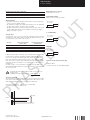
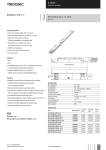
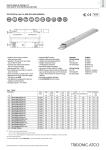
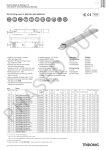
LED control gear
Compact dimming
Uconverter LCAI 50 W 1050 mA N020 DALI
ECO series
Product description
T
•1-channel LED control gear
•Independent LED control gear for indoor use
•Output current and output voltage adjustable
U
•FAN output 12 V
•NTC input channel
•Nominal life of 50,000 h (at ta max. with a failure rate of 5 %)
•Dimmable via DALI, 1 ... 10 V, potentiometer or PUSH function1
•Overload protection5
O
•Thermal protection5
•Short-circuit protection
22
•No-load protection
•Type of protection IP20
124,5
Technical data
216 – 264 V
Mains frequency
50 / 60 Hz
Typ. efficiency (at 230 V / 50 Hz / full load)
91 %
λ (at 230 V / 50 Hz)
0.95
THD
< 10 %
tc
Ø4,5
67
0.25 A
Input voltage range, AC
79
Rated current (at 230 V / 50 Hz / full load)
AS
E
220 – 240 V
D
111
Rated supply voltage
20 A / 400 µs
Control input
DALI, 1 ... 10 V, potentiometer
100 kΩ and PUSH function2
Ordering data
Stand-by power (at 230 V / 50 Hz)
<2W
Max. output voltage3
90 V
Type
Article number
Packaging
carton
Packaging
pallet
Weight per pc.
Dimming range
1 – 100 %
LCAI 0050/1050 N020 DALI
24166469
50 pc(s).
2,000 pc(s).
0.21 kg
PWM frequency
230 – 250 Hz
Set up time at 230 V
500 ms
Switch-off time (at full load)
100 ms
FAN output, voltage
12 V
FAN output, current4
50 mA
Max. casing temperature tc
85 °C
Max. casing temperature tc (at lifetime 50,000 h)
75 °C
Dimensions LxWxH
124.5 x 79 x 22 mm
PH
Inrush current
1 PUSH
function is not compatible to switchDIM.
21
... 10 VDC source with double or reinforced insulation with respect to AC mains.
Max. source current: 0.35 mA
3 No-load
4 Max.
5 On
operation.
permitted inrush current: 50 mA.
overload and over temperature the output power will be reduced.
Data sheet 08/13-LC007-8
Subject to change without notice.
www.tridonic.com
1
LED control gear
Compact dimming
Specific technical data
Type
Output
Typ. power
Output voltage range
Max. output current
Operating
temperature ta
350 mA
±6 %
25 W
2 – 74 V
–
-25 ... 50 °C
500 mA
±5 %
35 W
2 – 72 V
–
-25 ... 50 °C
700 mA
±5 %
50 W
2 – 71 V
–
-25 ... 50 °C
900 mA
±5 %
50 W
2 – 55 V
–
-25 ... 45 °C
1,050 mA (default)
±5 %
50 W
2 – 48 V
–
-25 ... 45 °C
48 V
±5 %
50 W
–
1,050 mA
-25 ... 45 °C
PH
AS
E
D
O
U
T
LCAI 050/1050 N020 DALI
Tolerance
Data sheet 08/13-LC007-8
Subject to change without notice.
www.tridonic.com
2
LED control gear
Compact dimming
Standards
EN 55015
EN 61000-3-2
EN 61347-1
EN 61347-2-13
EN 61547
EN 62384
IEC 62386-101
IEC 62386-102
DIN VDE 0710 part 14
Dip SWITCH position
Output
Position
350 mA
6
5
4
3
2
1
–
–
–
–
–
–
500 mA
on
–
–
–
–
–
700 mA
on
on
–
–
–
–
900 mA
on
on
on
–
–
–
1,050 mA (default)
on
on
on
on
–
–
48 V
on
on
on
on
–
on
T
Before use, always check Dip SWITCH setting.
Glow wire test according to EN 60695-2-11
960 °C passed.
U
PUSH function
Integrated Push function allows a direct dimming via push button. Push button
must be connected between the terminal block (PUSH) and Phase (L).
Maximum 10 LED control gears in series controlled by one or more push
buttons.
The maximum length of push cables is 15 m.
Dimming
Dimming range 1 % to 100 %
Control with:
•DALI signal
•PUSH function
•Potentiometer
•1 ... 10 V
Dimming characteristics
Digital dimming value
255
225
175
150
125
100
75
50
25
0
0
AS
E
DALI
200
10
20
30
40
The use of the push button inhibits the use of the 1...10 V signal. To
return to use of the 1...10 V signal keep the signal less than 0,5 V for at
least 2 seconds.
PUSH synchronisation
If more than one device is operated with a single key during PUSH operation,
asynchronous behaviour can occur, which will require manual resynchronisation
using the method described. It is recommended not to control more than four
devices using a single key. Should this be unacceptable, a synchronisation cable
will have to be used instead. Any 1-key dimmer that does not feature a central
control module (as each LED control gear will have its own controls) can develop
asynchronous behaviour (e.g. children might play with the key). The system
will then be out of sync, i.e. some lamps will be on, others off or the dimming
direction will differ from lamp to lamp.
D
Digital signal DALI
The control input is non-polar. The control signal is not SELV. Control cable has
to be installed in accordance to the requirements of low voltage installations.
Different functions depending on each module.
O
•Brief push (<1 s) switches the device ON and OFF. The device switch-ON at
light level set at switch-OFF
•When the push button is held (>1 s), the devices are dimmed. After repush
the devices is dimmed in the opposite direction.
50
60 70 80 90 100
Relative lighting level %
If the LED control gears are switched on, press the PUSH key for more than
one second (long PUSH) followed with a short push (<1 s). Now the devices are
switched off, do a long PUSH, the system will now be resynchronised.“
The PUSH function is not compatible to switchDIM. The wiring of the
PUSH function and switchDIM is not exchangeable.
Dimming characteristics as seen by the human eye
PH
Dimming characteristics as seen by the human eye. A linear dimming characteristic can be activated optionally via DALI (DALI command: SELECT DIMMING
CURVE).
1 ... 10 V function
The light intensity of the LEDs vary proportionally to the signal sent to the terminal. Intensity is null with a signal less than 1 V.
Potentiometer function
By rotating the potentiometer there is variation of the LED light intensity in a
proportionate or logarithmic way depending on the model of potentiometer used.
The use of a logarithmic potentiometer is recommended.
Synchronisation
A maximum of 10 devices in series can be controlled with a momentary-action
switch, potentiometer or 1...10 V interface.
Only one master device is permitted. (1 master + 9 slaves)
Maximum forward voltage
Note:
It’s not allowed to connect LED modules with a higher forward voltage
then declared, otherwise the LED control gear will be over loaded and
the expected nominal life time will be reduced.
This issue isn’t covered by the warranty.
Function of the PR terminal:
The PR connection can improve EMC behaviour, LED residual glow and immunity
(surge). The PR terminal must be connected to an earthed or non-earthed metal
surface such as a heat sink and/or luminaire housing. If connected to nonearthed components there may be a difference in potential compared to earth.
The PR connection need not be used, it merely serves to make improvements in
certain applications.
The maximum length of the synchronisation cable between the devices should
not exceed 4 m.
Data sheet 08/13-LC007-8
Subject to change without notice.
www.tridonic.com
3
LED control gear
Compact dimming
Wiring type and cross section
Strain relief for Ø 3 – 8 mm.
Maximum loading of automatic circuit breakers
Installation Ø
LCAI 050/1050 N020 DALI
C10
C16
B10
B16
1.5 mm2
1.5 mm2
1.5 mm2
1.5 mm2
15
25
9
15
Input / Output terminal
Please use only one wire per terminal.
Wiring guidelines
•The cables should be run separately from the mains connections and mains
cables to ensure good EMC conditions.
•The maximum secondary cable length at the terminals is 5 m. The LED wiring
should be kept as short as possible to ensure good EMC.
•The LED control gear does not have polarity reversal protection on the secondary side. LED modules that do not have polarity reversal protection may be
damaged if polarity is reversed.
wire preparation:
0.5 – 2.5 mm²
5.5 – 6.5 mm
Thermic sensor
If a temperature sensor is to be used either the preinstalled resistor in the NTC
terminal or the “JP51” jumper must be removed, depending on the device version. A temperature sensor can then be connected.
Start operation temperature
(3 V Req = 26 kΩ)
Total switch-off temperature
(2,2 V Roff = 15 kΩ)
100 K
55 °C
72 °C
150 K
65 °C
80 °C
220 K
75 °C
90 °C
O
NTC value
wire preparation:
0.2 – 1.5 mm²
U
1...10 V/NTC / FAN
T
Automatic circuit breaker type
4.5 – 5.5 mm
PUSH / DA
wire preparation:
0.5 – 2.5 mm²
D
Component tolerances are not considered.
AS
E
In DALI operation a failure of the lamp can be communicated by short-circuiting
the NTC port or by leaving it open (DALI command: QUERY FAILURE STATUS).
In case of an open/short-circuit at the NTC input, the unit will identify a lamp
fault. At an LED module or NTC temperature of 75 °C, there will be a voltage
drop of 3 V and/or a resistance value of 26 kOhm. From an LED module or NTV
temperature of 90 °C, there will be 2.2 V / 15 kOhm and the LED control gear
will switch off.
If no NTC resistance is connected and the “lamp fault” message (DALI command: QUERY FAILURE STATUS) is not required, a resistance of only 220 kOhm
has to be connected.
8.5 – 9.5 mm
Connector for the synchronisation cable
SPOX from Molex
•Plug for cable (art. no. Molex: 0022433020)
Information about the correct handling of LEDs can be found in the
u brochure
“Installation instructions and guidelines” Ê www.tridonic.com
PH
Short/soft start mode
The soft start mode is enabled/disabled by pressing a momentary-action switch
at the Push L input, while mains voltage is applied to the LED control gear. The
LED control gear will then operate in soft and/or short start mode.
Short start mode between 1 – 100 % < 0.7 s: default setting
Soft start mode between 1 – 100 % > 1.5 s
PUSH
PUSH L
PRI
N
L
Data sheet 08/13-LC007-8
Subject to change without notice.
www.tridonic.com
4
LED control gear
Compact dimming
Wiring diagram 1...10 V or potentiometer
Wiring diagram PUSH function
6 5 4 3 2 1
6 5 4 3 2 1
Uconverter
LCAI 50 W 1050 mA N020 DALI
NTC
FAN
12 V
–
+
PUSH
U
N
L
Max. 10 devices in series (1 master + 9 slaves)
6 5 4 3 2 1
–
SEC +
–
1...10 V +
O
6 5 4 3 2 1
–
SEC +
–
1...10 V +
NTC
–
+
FAN
12 V
SYNC –
–
+
+
Uconverter
LCAI 50 W 1050 mA N020 DALI
PR
DA1
DA2
PUSH L
N
L
NTC
FAN
12 V
–
+
PR
DA1
DA2
PUSH L
PRI
N
L
AS
E
PRI
D
+
FAN
12 V
PRI
Max. 10 devices in series (1 master + 9 slaves)
Uconverter
LCAI 50 W 1050 mA N020 DALI
NTC
–
+
PR
DA1
DA2
PUSH L
PRI
–
+
–
SYNC +
–
+
PR
DA1
DA2
PUSH L
SYNC –
–
1...10 V +
T
+
1...10 V / potentiometer
–
+
SYNC –
–
SEC +
–
1...10 V +
Uconverter
LCAI 50 W 1050 mA N020 DALI
–
SEC +
Wiring diagram DALI
6 5 4 3 2 1
PH
+
–
+
SYNC –
Uconverter
LCAI 50 W 1050 mA N020 DALI
–
SEC +
–
1...10 V +
NTC
FAN
12 V
PR
DA 1
DA 2
PUSH L
PRI
–
+
DALI
N
L
Data sheet 08/13-LC007-8
Subject to change without notice.
www.tridonic.com
5