1
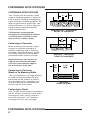
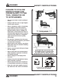
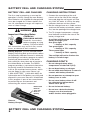
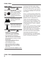
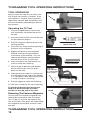
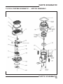
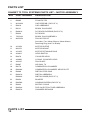
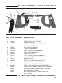
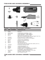
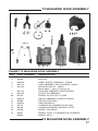
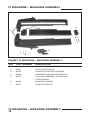
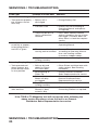
DANGER
READ AND OBEY ALL SAFETY AND OPERATING
INSTRUCTIONS BEFORE OPERATING TOOL.
RAMSET T3 TOOL SYSTEMS
T3SS SINGLE SHOT & T3 MAGAZINE
OPERATOR’S SAFETY & OPERATING
INSTRUCTION MANUAL
T3SS
T3MAG
T3SS Single Shot
T3 Magazine
GAS POWERED, LOW VELOCITY
PISTON TYPE FASTENING TOOL
SAFETY INTRODUCTION
DANGER
DANGER
THIS TOOL IS TO BE USED ONLY BY PROPERLY TRAINED
OPERATORS. ATTEMPTING TO HANDLE OR OPERATE THE
T3 GAS POWERED TOOL WITHOUT PROPER TRAINING CAN RESULT
IN SERIOUS INJURY TO THE OPERATOR OR BYSTANDERS.
! Read, understand and follow the instructions in
the tool manual before attempting to use the tool.
! Operators and Bystanders must wear eye and
hearing protection.
! Never close tool with hand over the fastener loading
end of the tool. A serious hand injury from penetration
by the piston or fastener could result.
! The gas in fuel cells is under pressure and the gas
is flammable.
! Do not open, puncture or burn fuel cells.
! Store fuel cells in a well ventilated area, at temperatures
below 50° C (122° F) and out of the sunlight.
! Keep fuel cells away from flames, sparks and heat.
! Do not attempt to recharge, refill or recycle fuel cells.
! Never operate the T3 tool if flammable or explosive
materials are nearby.
DANGER
Just as no one can merely read a book about driving an automobile and then
hope to drive one safely, no one should attempt to use T3 gas powered tools
without adequate, competent personal instruction.
No automobile instruction book or instructor can forewarn a learner against
all possibilities and emergencies, nor can printed material detail all possible
conditions surrounding the use of Ramset tools and products.
Responsibility for the safe and proper use of this tool rests with the tool user
and the employer.
SAFETY INTRODUCTION
2
DANGER
DANGER SAFETY INSTRUCTIONS
Preparation For Fastening
Acceptable Base Materials
The gas powered T3 tools are
suitable for use in the following
base materials only:
• Poured Concrete
Solid Concrete and
Precast Concrete
• Structural Steel
• Concrete Block and Horizontal
Joints in Brick or Masonry Walls
Never attempt to fasten into any other
type of material. Fastening into other
materials can cause blindness or other
serious injury.
Never attempt to fasten into very hard
or brittle materials such as cast iron,
tile, glass, or rock of any type. These
materials can shatter, causing the fastener
and/or base material fragments to fly free
and cause serious injury to the tool operator
and others.
Never fasten into any base material that
does not pass the Center Punch test.
Failure to assure the suitability of the base
material can result in serious injury to the
eyes or other body parts.
Structural Steel
Solid or Hollow
Block
Horizontal Joints
only in Brick Walls
Center Punch Test
Center Punch Test Results
ALWAYS WEAR SAFETY GOGGLES
WHEN PERFORMING THIS TEST.
1. If the fastener point is flattened,
the material is too hard for a
powder actuated fastening.
1. Always check the material being
fastened into for hardness before
attempting any fastening operation.
2. Using a fastener as a center punch,
strike the fastener against the work
surface using an average hammer
blow and check the results.
DANGER
2. If the fastener penetrates the material
easily, the material is too soft.
3.If the material cracks or shatters,
the material is too brittle.
4. If the fastener makes a small
indentation into the material, the
material is suitable for fastening.
SAFETY INSTRUCTIONS
3
FASTENING APPLICATIONS
3"
FASTENING APPLICATIONS
Your T3 tools can be used for a wide
range of fastening needs in a variety of
base materials. Reading and following
these important fastening guidelines will
help you get the best results from your
tool and fasteners, as well as help you
perform these fastening operations
safely and effectively.
T3 fastenings are permanent
fastenings so attempting to remove
a fastener from concrete or steel
may result in a serious injury.
Fastening to Concrete
When fastening into concrete, always
maintain a minimum spacing of 3”
between fastenings and 3” from any
free edge. Concrete thickness should
be at least three times the intended
penetration depth into the concrete.
Driving fasteners too close to an
edge or too close to each other
can cause the concrete edge to
fail or fasteners to fly free.
Fastening to Concrete
Block or to Masonry Walls
3"
Your T3 tools can be used for fastening on
the flat surfaces of structural steel. When
fastening into steel, always maintain a
minimum spacing of 1-1/2” between
fastenings and 1/2” from any edge.
FASTENING APPLICATIONS
4
MIN.
PENETRATION - THIN GAUGE
METAL TO CONCRETE
3"
MIN.
3"
MIN.
3" MIN.
3" MIN.
SPACING - THIN WOOD
STRIP TO CONCRETE
3"
1/2"
MIN.
1/2"
MIN.
Take care to observe a 3” edge distance
to avoid cracking the block and over
penetration of the fastener to avoid a
loss of holding value. Fastenings may
also be made into the horizontal joint
but not into the vertical joint.
Fastening to Steel
MIN.
MIN.
1-1/2"
MIN.
1-1/2"
MIN.
SPACING
STEEL TO STEEL
3" MIN.
1/2"
MIN.
1-1/2"
MIN.
DANGER SAFETY INSTRUCTIONS
FAILURE TO FOLLOW
INSTRUCTIONS CAN
CAUSE INJURY TO THE
TOOL OPERATOR OR
TO BYSTANDERS.
• Use the tool only in well ventilated
areas.
Ceilings
Walls
• Always hold the tool at right angles
to the work surface.
• Never attempt to make a fastening
at an angle to the work surface.
• While the tool can be used in any
position (floor, wall or ceiling) it is
important to have both the nose of
the tool and support foot in contact
with the work surface to minimize
spall and make the best quality
fastenings.
Floors
The T3 tools may be used
in any position.
• Do not put a fastener into the nose
of the tool until just before you intend
to make the fastening.
• Never place your hand or any other
body part over the fastener loading
end of the tool.
• Never carry the tool with your finger
on the trigger.
• Never leave the tool unattended or
allow anyone to operate it without
first being trained.
90°
Keep both the nose of the tool
and support foot in contact with
the work surface and hold tool
perpendicular to the work surface.
• Never engage in horseplay with
the tool.
• Always keep the tool pointed away
from yourself or others.
• Never operate the tool if explosive
or flammable materials are nearby.
• Keep the tool and supplies locked
up and out of the reach of children.
DANGER
Keep tool locked up and
out of reach of children
SAFETY INSTRUCTIONS
5
BATTERY CELL AND CHARGING SYSTEM
BATTERY CELL AND CHARGER
CHARGING INSTRUCTIONS
The first step in preparing a new tool for
operation is to fully charge the new Battery.
New Batteries are shipped discharged and
must be charged for 24 hours before first
use. All subsequent charges will require at
most a 3 hour charge.
1. Connect the round plug of the wall
mount unit to the front of the charger
base and plug the wall mount unit into
any 120V AC outlet. A LED by the plug
indicates the base unit has power.
WARNING
Important Charging Notes
CHEMICAL/
EXPLOSION HAZARD
Read ALL instructions
before charging or using
battery. Failure to follow
ALL instructions may result in fire, severe
burns, or release of toxic materials.
Battery Disposal: The EPA certified RBRC®
Battery Recycling Seal on the nickel-cadium
(Ni-Cd) battery indicates Ramset is voluntarily
participating in an industry program to collect
and recycle these batteries at the end of
their useful life, when taken out of service in
the United States or Canada. The RBRC®
program provides a convenient alternative
to placing used Ni-Cd batteries into the
trash or the municipal waste stream, which
may be illegal in your area. Please call
1-800-8-BATTERY™ (1-800-822-8837) for
information on Ni-Cd battery recycling and
disposal in your area. Ramset’s involvement
in this program is part of our commitment
to preserving our environment and
conserving our natural resources.
Holds both
Ramset
stick and
New T3
Battery
2. Set the charger base on a stable surface
and insert the battery or batteries, contact
first, into the opening of the charger base.
3. The T3 charger incorporates a charge
level indicator to inform the user of the
battery charge level.
A red light will illuminate at all times
during a charge cycle.
One green light = battery at 50% capacity
Two green lights
= battery at 75% capacity
Three green lights
= battery at FULL capacity
The red light will not be lit when the
battery is at full charge.
CHARGING DONT’S
• Do not charge battery when
temperature is below 40°F (5°C).
• Do not drop battery or charger.
• Do not allow metal objects to come in
contact with battery terminals.
• Do not puncture or attempt to open
battery case or cells.
• Do not store battery where it will
be subjected to temperatures
above 120°F (49°C).
• Do not incinerate battery.
• Do not use a defective battery
charger, one that overheats
and/or smokes when plugged in.
Ramset
Battery Charger
BATTERY CELL AND CHARGING SYSTEM
6
INSTALLING THE BATTERY
INSTALLING THE BATTERY
#1
• Insert the battery into the tool as
shown on the right with the clip
facing to the side.
• The battery has two positions in
the tool:
1.The “OFF” position—as shown
in picture #1 to the right.
2.The “RUN” position—as shown
in picture #2 to the right.
• To operate the tool be sure the
battery is fully inserted into the
tool. After installing the battery,
note the LED light on the right
side of the handle.
NOTE:
OFF position
shown in
small window
#2
• If the light flashes green, the tool
is powered.
• If the light flashes red, the battery
requires charging.
• If the light is solid green and the
fan is running, the tool is ready to
take the next shot.
• If the light is solid red and the fan
is not on, the battery needs to be
recharged.
• If the tool will not be used for a
short period of time, click the battery
back into the “OFF” position. This will
prevent the tool from being fired.
• If the tool will not be used for extended
periods of time, remove the battery
and store in the tool case.
NOTE: Battery
fully
inserted
into tool
#3
NOTE: LED Light
INSTALLING THE BATTERY
7
FUEL CELL
FUEL CELL
DANGER
EXPLOSION/FIRE HAZARD
Read ALL safety instructions
before using or handling the
fuel cell. Failure to follow
ALL instructions may result
in explosion or fire. This
may cause severe personal
injuries or property damage.
Keep the fuel cell away
from heat, sparks and
open flame. Exposure to temperatures
above 120°F (49°C) may
cause the fuel cell to burst,
releasing flammable gas.
WARNING
• Sunlight can raise the inside
temperature of an unventilated
car or van to above 140°F (60°C).
• Do not puncture or attempt to
open the fuel cell; it is non-refillable.
• Do not incinerate, reclaim or recycle
the fuel cell.
• Do not smoke while installing or
removing the fuel cell.
• Do not inhale the spray.
• Keep out of the reach of children.
• Store fuel cell(s) in well-ventilated
areas only.
• Do not reuse fuel cell, adaptor or seal.
FUEL CELL
8
The Ramset Fuel Cell contains liquid
hydrocarbon fuel. This provides enough
fuel to drive approximately 1,000 fasteners.
The Fuel Cell is designed for proper operation
at temperatures between 15°F (-5°C) and
120°F (49°C)
There is a second container inside the fuel
cell. The inner container holds the fuel. The
space between the inner container and the
outer cylinder is filled with a gas, called the
propellant, which is under pressure.
To eject the fuel, propellant pressure
squeezes the inner fuel container, much
as you squeeze a tube of toothpaste. This
squeezing action ensures that all the fuel
is used, and that the T3 tools can operate
in any position.
Because of this container-within-a-container
design, you might hear the sound of fluid
when shaking the fuel cell after all the
fuel has been used. This is the propellant,
which remains between the containers
even after all the fuel has been expelled.
If you expose the empty fuel cell to
extreme temperatures, the propellant gas
will expand and could cause the container
to burst, releasing flammable gases.
INSTALLING THE FUEL CELL
INSTALLING THE
FUEL CELL
• The T3 fuel cell comes ready to use.
There is no need for additional steps
to prepare the fuel cell. The fuel cell
also incorporates a usage indicator,
to indicate a new fuel cell from a used
fuel cell.
• There is a membrane over the top of
the fuel cell adaptor. If the fuel cell
has been used the membrane will
have been pierced. See picture on
the right
Fuel Cell
Top of the Fuel Cell
#1
1.Locate the port on the left rear of
the tool and slide the fuel cell into
position.
2.Firmly push the fuel cell completely
into the pocket until the adaptor on
top of the fuel cell clicks into the
tool.
#2
3.The fuel cell is now ready.
• To remove the fuel cell from the tool,
push and release the “Fuel Eject”
button located on the front left side
of the tool.
• Excessive removal and installation
of fuel cell will reduce the number
of shots per cell.
#3
INSTALLING THE FUEL CELL
9
T3SS TOOL OPERATING INSTRUCTIONS
TOOL OPERATION
Always check the tool first to make sure that
it does not contain a fastener. If the tool
contains a fastener from a previous application,
remove both the battery and the fuel cell
before attempting to remove the fastener.
Insert battery
Operating the T3SS Tool
1. Insert a charged battery into the tool
with the battery contacts to the front.
2. Insert a good fuel cell into the tool as
described on page 9.
3. With your finger off the trigger, insert
the fastener you wish to use in the
nose of the tool. Do not force the
fastener into the tool such that you
cause the work contact element to
be pushed up into the tool body.
4. Note that the LED light on the side
of the handle is a flashing green
indicating the the tool is now ready
to make a fastening.
Insert fuel cell
5. Place the tool in the spot where
you want to make your fastening.
6. With the tool in place and the supporting
foot in contact with the work surface,
hold the tool perpendicular compress
the nose against the work surface and
pull the trigger to make the fastening.
7. The tool is now ready for the next
fastener.
To avoid overheating the tool, do not
completely close off the air intake section
on the top end of the tool.
Insert fastener
Removal of Rear Foot Assembly
1. Find the knob on the rear of the tool,
turn the knob counter clockwise until
it stops
90°
2. Push the knob inward
3. Push the foot back, off of the
handle assembly
4. Reverse the above procedure
for installation
Hold tool perpendicular
In contact with work surface
T3SS TOOL OPERATING INSTRUCTIONS
10
QUICK CHANGE NOSE
QUICK CHANGE NOSE
The T3SS tool is equipped with a quick
change nose. This feature allows the user
to change the work contact element to
meet various fastening needs. The work
contact element can be changed without
the use of tools by following these steps:
Removal
1. Remove battery from the tool !!!
2. Firmly grasp the end of the
Work Contact Element and turn
it 90 degrees
Turn 90°
3. Pull the Work Contact Element
from the tool.
Replace
1. Orient the Work Contact Element
so that the notched or flat portion
is toward the back or the tool
2. Firmly push the Work Contact
Element up into the nose piece.
3. Slightly twist the Work Contact
Element to be sure it is fully
engaged in the nose. NOTE: There
should be no open gap between the
shear block plate and the nose piece.
Pull
4. Insert the battery and operate
the tool.
Work Contact Elements
P/N: M150200 – To be used with fasteners
with pre-mounted 1/2” washers.
P/N: E150100 – To be used with straight
pins, fasteners with eyelets, and fastener
assemblies.
Note gap,
rotate work
contact
element until
gap disappears
QUICK CHANGE NOSE
11
T3 MAGAZINE TOOL OPERATING INSTRUCTIONS
TOOL OPERATION
Always check the tool first to make sure
that it does not contain a fastener. If the
tool contains a fastener from a previous
application, remove both the battery and
the fuel cell before attempting to remove
the fastener.
Insert battery
Operating the T3 Tool
1. Insert a charged battery into the tool
with the battery clip toward the rear of
the tool.
2. Insert the Ramset fuel cell into the tool
as described on page 6.
3. Pull the magazine follower back to the
locking position.
Insert fuel cell
4. Insert the nail strips into the opening in
the back of the magazine.
5. Slightly pull back on the magazine
follower while pressing the button
at the back of the follower. This will
release the follower making contact
with the back of the last pin strip.
6. Place the tool in the spot where you
want to make the fastening.
7. With the tool in position and perpendicular to the work surface; press
down on the tool.
8. Note that the fan motor is running and
the LED light on the side of the handle
is a solid green color indicating the tool
is ready to make a fastening.
Insert fastener
Hold tool
perpendicular
in contact with
work surface
90°
9. Pull the trigger to make the fastening.
10.The tool is ready for the next fastening.
To avoid overheating the tool do not
hold your hand over the air intake
section on the top end of the tool.
Knob
Removing The Fastener Magazine
On occasion the fastener magazine may
need to be removed to clear a fastener
jam. To do so, unscrew the knob at the
rear of the tool. Then press the knob. Slide
the magazine rearward to remove it from
the tool.
T3 MAGAZINE TOOL OPERATING INSTRUCTIONS
12
PARTS SCHEMATIC
T3 TOOL SYSTEM SCHEMATIC – MOTOR ASSEMBLY
PARTS SCHEMATIC
13
PARTS LIST
RAMSET T3 TOOL SYSTEMS PARTS LIST – MOTOR ASSEMBLY
KEY PART NUMBER
DESCRIPTION
1
B0017 GRILL, CAP
2
B0095 FOAM FILTER
3
901065A CAP SCREWS ( PKG OF 4)
4
B0016 CAP ASSEMBLY
5
B0121 SPARK PLUG WIRE
6
B0061A PC BOARD SCREWS (PKG OF 3)
7
B0040 PC BOARD
8
7505164 SPARK PLUG ASSEMBLY
9
900525A FAN MOTOR KIT
(Includes: Fan, Motor Sleeve, Motor Mount, Retaining Ring and Fan Blade)
10 401356 MOTOR SLEEVE
11 900470 MOTOR MOUNT
12 401355 MOTOR RETAINING RING
13 404601 HEAD SWITCH
14 B0078 CYLINDER HEAD
15 403992 O-RING, CYLINDER HEAD
16 403167 FAN BLADE
17 B0097 AIR DAM, T3
18 B0178 COMBUSTION CHAMBER
19 B0046A COMBUSTION CHAMBER WEAR PLATE
20
B0068 PISTON STOP RING
21 B0031A PISTON ASSEMBLY
B0034A PISTON RINGS (PKG OF 2)
22 B0053 BUMPER
23 B0059A HOUSING SCREW (PKG OF 3)
24 B0042 SLEEVE O-RING
25 B0054A FUEL INJECTION TUBE ASSEMBLY
26 B0037A CHAMBER SPRINGS
PARTS LIST
14
T3 TOOL SYSTEMS – HANDLE ASSEMBLY
RAMSET T3 TOOL SYSTEMS PARTS LIST – HANDLE ASSEMBLY
KEY PART NUMBER
DESCRIPTION
1
333380 2
404619 3
404490 4
7405091 5
B0134 6
B0093 7
B0006A
8
B0050A
9
B0160
10 B0100A
11 B0176
12 B0144
13 B0018
14 B0090A
15 B0011
16
B0210A
18
B0160A
B0029
B0030
B0092
B0022
KNOB ASSEMBLY
INSULATOR (2) NOT SHOWN
TRIGGER SWITCH
SCREWS, #2 X 5/8”, TRIGGER SWITCH
SPARK UNIT – MEFI
EFI JUNCTION BOARD
TRIGGER ASSEMBLY
FUEL CONNECTION ASSEMBLY
FUEL VALVE ASSEMBLY
HANDLE SCREWS
LEFT & RIGHT HANDLE ASSEMBLY
REAR FOOT ASSEMBLY (T3SS ONLY)
SPACER PLATE
FUEL EJECT BUTTON & LATCH KIT
BATTERY TERMINAL ASSEMBLY
BELT HOOK KIT (NOT SHOWN)
FUEL VALVE W/SPACER PLATE ASSEMBLY
HANDLE TO HOUSING BUSHING (NOT SHOWN)
HEAD TO HANDLE BUSHING (NOT SHOWN)
BATTERY (NOT SHOWN)
BATTERY CHARGER & POWER ADAPTOR
(NOT SHOWN)
T3 TOOL SYSTEMS – HANDLE ASSEMBLY
15
T3SS NOSE AND HOUSING ASSEMBLY
RAMSET T3SS NOSE AND HOUSING ASSEMBLY
KEY PART NUMBER
DESCRIPTION
1
B0001
2
B0096
3
B0052T3SS 4
B0217A
5
B0175
6
E150100
—
M150200
8
B0047A
—
B0171
9
B0179
10
B0218
11
100008A
12
B0037A
13
B0059A
14
B0057
—
EM150302
—
12388
—
B0163
HOUSING
SHROUD
NOSE/SLEEVE ASSEMBLY T3SS
CAGE ASSEMBLY, T3SS/T3SSMAG
SHEAR BLOCK PLATE KIT, T3SS
(USE WITH TOOLS BEFORE S/N 1407100277 OCT 07)
WORK CONTACT ELEMENT (WCE)
MAGNETIC WORK CONTACT ELEMENT
GUIDE BLOCK ASSEMBLY
SPACER, STAND-OFF NUT
SHROUD PLUG
WCE RETENTION KIT
(TOOLS WITH S/N 1407100278 OR LATER, OCT 07)
AUXILIARY SHROUD T3SS
CAGE SPRINGS (QTY 2)
HOUSING SCREWS (PKG 3)
SCREW, CAGE TO COMBUSTION CHAMBER
4 REQUIRED - SOLD INDIVIDUALLY
SHOULDER SCREW FROM B0175 KIT (EA)
SPRING FROM KIT B0175 (EA)
NUT FROM KIT B0175
T3SS NOSE AND HOUSING ASSEMBLY
16
T3 MAGAZINE NOSE ASSEMBLY
8
7
2
5
9
8
13
10
11
12
13
4
1
3
RAMSET T3 MAGAZINE NOSE ASSEMBLY
KEY PART NUMBER
DESCRIPTION
1
B0001 2
B0199 3
B0052A 4
B0217A 5
B0110A 7
B0111A
8
B0122A
8A
B0128
9
B0031A
10
B0068
11
B0037A
12
B0178
13
B0209
14
B0188
15
B0057
B0058
HOUSING
SHROUD
NOSE / SLEEVE ASSEMBLY, T3MAG
CAGE ASSEMBLY WITH SCREWS, T3MAG
SHEAR BLOCK KIT, T3MAG
Shear Block, T-Nuts (2), Screws (2)
PIN GUIDE ASSEMBLY W/SET SCREW
ACTUATOR ASSEMBLY
SCREW, ACTUATOR TO CAGE
PISTON ASSEMBLY W/PISTON RINGS
PISTON STOP RING
CAGE SPRING (2)
COMBUSTON CHAMBER W/AIR DAM
HOUSING SCREWS & SECURITY STOP
SCREW, PIN GUIDE
SCREW. CAGE TO COMBUSTION CHAMBER
SCREW, M5-10
T3 MAGAZINE NOSE ASSEMBLY
17
T3 MAGAZINE – MAGAZINE ASSEMBLY
2
3
1
4
5
6
7
RAMSET T3 MAGAZINE – MAGAZINE ASSEMBLY
KEY PART NUMBER
DESCRIPTION
1
B0203
MAGAZINE LEFT & RIGHT HALF
2
B0204
FRONT & REAR RAILS
3
B0205
CONNECTION BLOCK & SCREWS
4
B0206
CONNECTION BLOCK SCREWS ONLY
5
B0207
FOLLOWER ASSEMBLY W/CONSTANT
FORCE SPRING
6
B0208
MAGAZINE SCREWS
7
B0147
LOCKOUT BRACKET
T3 MAGAZINE – MAGAZINE ASSEMBLY
18
SERVICING / TROUBLESHOOTING
SYMPTOM
POSSIBLE PROBLEMS SERVICE
Preparing Tool for Operation—Battery/Charger Problems
—Battery Cell does not —Inoperative indicator —Try Battery Cell in tool after 3 hours appear to accept lights on charger on charge cycle. If tool LED is
charge. Green charger green, charger lights are not
light does not come on working properly. Replace charger,
or monitor charging time to ensure Battery Cell has adequate time for recharging. It’s normal for Battery to feel warm after properly charging.
—Battery Cell damaged —Replace Battery Cell
or cycle life exhausted
—Damaged charger
—Discontinue use immediately and unplug from power source. Replace charger and tag or dispose of charger to prevent accidental reuse or connection to power source.
—Flashing lights on —Damaged Battery Cell —Replace Battery
charger base unit
—Battery Completely —Allow battery to charge for
Drained 5 minutes
Normal Stage of Operation
—Fan does not run
—Battery in off position —Fully insert Battery
—tool LED is off
—Battery Cell is —Charge Battery Cell according to not charged Operating Manual. —Battery terminals or —Clean Battery Cell terminals.
battery contacts are Battery Cell contacts as required.
oily, dirty, or corroded
—Fan does not run, —Battery Cell is or runs slower than discharged
normal—tool LED is red
—Charge Battery Cell
—Fan does not run, —Possible electronics
—Remove, reinsert the Battery
tool LED flashes error
Contact Authorized Ramset
red/green Distributor Sales Representative
for service.
Pre-Combustion/Combustion Stage of Operation
—Work Contacting —Work Contacting —Remove and inspect Work Contact
Element does not Element is bent, or Element. Repair or replace Work
depress fully—tool build-up of debris in Contact Element as required.
does not operate nose restricts operation
—O-Ring pinched
—Contact Authorized Ramset Distributor Sales Representative for service.
(For T3 Magazine tool only) — Tool is out of fasteners —Add fastener strip
—Tool will not cycle—fan—Fuel Cell is empty
runs, LED is green
—Replace Fuel Cell
—Spark does not occur. —Contact Authorized Ramset Distributor Sales Representative for service.
SERVICING / TROUBLESHOOTING
19
SERVICING / TROUBLESHOOTING
SYMPTOM
POSSIBLE PROBLEMS SERVICE
Power/Exhaust Stage of Operation
—Tool operates properly, —Battery cell is but fasteners do not discharged
drive fully
—Charge Battery Cell
—Fuel Cell is low
—Check Fuel Cell according to Operating Manual and replace
as required.
—There may be loss of —Press Work Contact Element seal in combustion against workpiece for one minute.
chamber
Pull trigger. If fastener does not
drive, there is a leak that requires service.
—Tool operates —Fuel Cell is low
—Check Fuel Cell according to
erratically or appears Operating Manual
to be losing power—
tool LED is green
—Filter element is dirty, —Remove Filter element and clean causing tool to overheat according to Operating Manual. Use safe cleaning solution
to remove stubborn debris.
—Tool Sleeve or O-Rings are dirty
—Clean tool per Cleaning Procedure
Returning/Purging Stage of Operation
—Tool operated and —Built-up dirt and —Clean Piston and Nose bore with
drove fastener, but debris on Piston safety solvent. See Cleaning piston did not return
or in Nose bore Procedure.
to start position
—Mushrooming of
—Contact Ramset Distributor
Piston Tip Sales Representative for service.
—Exhaust ports on the —Return tool to Authorized
Sleeve are dirty Ramset Distributor Sales
or clogged. Representative for service.
—Tool (Sleeve) or O-Rings are dirty
—Clean tool per Cleaning Procedure
—Tool does not open —Work Contacting —Clean tool or replace Work after tool fires Element is bent, Contacting Element as required.
or tool is dirty
If the T3SS or T3 Magazine tool will not operate after following the
above service directions, return the tool to an Ramset
Distributor Sales Representative for service.
SERVICING / TROUBLESHOOTING
20
WARRANTY
RAMSET GAS TOOL SYSTEMS WARRANTY AND LIMITATIONS
Ramset warrants that new T3SS and
T3 Magazine systems power fastening
tools, parts and accessories will be
free from defects in material and
workmanship for the period shown
below.
TWO-YEAR/50,000 SHOT WARRANTY
A two-year/50,000 shot warranty, which
ever comes first, will apply to all parts,
except those listed below as normal
wearing parts, or parts which are
specifically covered by an extended
warranty.
SIX-MONTH/10,000 SHOT WARRANTY
A six-month/10,000 shot warranty applies
to the following parts, which are considered
normal wearing parts:
• Bumper
• Piston Assembly
• O-Rings
• Piston Rings
The warranty period is based off of tool
build date, determined from the tool serial
number. Ramset may extend the warranty
time frame from the date of purchase with
a qualifying document proving date of
purchase.
WARRANTY STATEMENT
This warranty is void as to any tool which
has been subjected to misuse, abuse,
accidental or intentional damage, use with
fasteners, fuel, battery, or battery chargers
not meeting Ramset specification, size, or
quality, improperly maintained, repaired
with other than genuine T3 replacement
parts, damaged in transit or handling, or
which, in Ramset’s opinion, has been altered
or repaired in a way that affects or detracts
from the performance of the tool.
Ramset MAKES NO WARRANTY,
EXPRESSED OR IMPLIED, RELATING
TO MERCHANTABILITY, FITNESS, OR
OTHERWISE, EXCEPT AS STATED ABOVE
and the liability AS STATED ABOVE AND
AS ASSUMED ABOVE is in lieu of all other
warranties arising out of, or in connection
with, the use and performance of the tool,
except to the extent otherwise provided by
applicable law.
Ramset SHALL IN NO EVENT BE
LIABLE FOR ANY DIRECT, INDIRECT, OR
CONSEQUENTIAL DAMAGES, INCLUDING,
BUT NOT LIMITED TO DAMAGES WHICH
MAY ARISE FROM LOSS OF ANTICIPATED
PROFITS OR PRODUCTION, SPOILAGE
OF MATERIALS, INCREASED COST OF
OPERATION OR OTHERWISE.
Ramset reserves the right to change
specifications, equipment, or designs
at any time without notice and without
incurring obligation.
Ramset’s sole liability hereunder will be
to replace any part or accessory which
proves to be defective within the specific
time period. Any replacement part or
accessory provided in accordance with
this warranty will carry a warranty for the
balance of the period of warranty applicable
to the part it replaces. This warranty does
not apply to part replacement required due
to normal wear.
WARRANTY
21
FOR TOOL REPAIR SERVICE CONTACT YOUR LOCAL
AUTHORIZED RAMSET DISTRIBUTOR OR TO FIND
YOUR NEAREST RAMSET TOOL REPAIR CENTER
VISIT OUR WEB SITE AT WWW.RAMSET.COM
OR CALL 800-241-5640
Concrete Fastening Systems
Glendale Heights, IL 60139
800-RAMSET6 (1-800-726-7386)
www.ramset.com
Buy with Confidence...
Buy From Your Authorized Distributor
AN ILLINOIS TOOL WORKS COMPANY
© ILLINOIS TOOL WORKS 2008
PRINTED IN THE U.S.A.
Form No. B0169-11/08