1
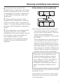
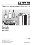
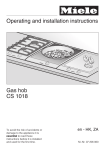
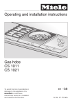
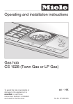
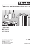
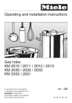
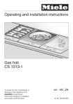
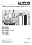
Installation instructions
Gas hob
KM 404 / KM 405
KM 406
KM 414 / KM 417
To avoid the risk of accidents or
damage to the appliance, it is
essential to read these
instructions before it is installed
and used for the first time.
en - GB
M.-Nr. 04 930 603
G This appliance can be used in countries other than those specified on the
appliance. It is, however, set up for connection to the gas and electricity
supplies in the countries specified. For use in other countries please contact
the Miele spare parts or customer service department in your country.
D Das Gerät ist auch für den Gebrauch in anderen als auf dem Gerät
angegebenen Bestimmungsländer zugelassen. Die landesspezifische
Ausführung und die Anschlussart des Gerätes haben wesentlichen Einfluss auf
den einwandfreien und sicheren Betrieb. Für den Betrieb in einem anderen als
auf dem Gerät angegebenen Bestimmungsland wenden Sie sich bitte an den
für das Land zuständigen Kundendienst.
E El aparato está autorizado para el uso en países diferentes a los países de
destino indicados. La ejecución específica para cada país y el tipo de
conexión del aparato influyen de forma decisiva en el funcionamiento correcto
y seguro. Para el funcionamiento en un país diferente al país de destino
indicado en el aparato, consulte al Servicio Post-venta autorizado para el país.
F Cet appareil est également homologué dans des pays différents de ceux
mentionnés sur l'appareil. Pour que l'appareil fonctionne parfaitement et en
toute sécurité, il est important de disposer de l'exécution spécifique au pays et
du type de raccordement approprié. Pour le fonctionnement dans un pays
autre que celui spécifié sur l'appareil, veuillez vous adresser au service
après-vente du pays où sera installé l'appareil.
I L'apparecchio può essere usato anche in paesi diversi da quello indicato
sull'apparecchio stesso. Tuttavia, le varianti specifiche di un determinato paese
e il tipo di allacciamento alla rete hanno un'importanza fondamentale per il suo
sicuro e corretto funzionamento. Per questo se si vuole usare l'apparecchio in
un paese diverso rivolgersi al servizio di assistenza tecnica Miele del paese in
cui si intende usarlo.
M Het apparaat is ook toegelaten voor gebruik in andere landen dan de landen
die op het apparaat vermeld staan. De specifieke uitvoering en de aansluitwijze
zijn van groot belang voor het goed en veilig functioneren. Neem daarom
contact op met de Technische Dienst van de fabrikant in uw land als u het
apparaat in een land wilt gebruiken dat niet op het apparaat vermeld staat.
2
Gas-heated appliances
Safety precautions to take if you smell gas
ß Turn off the gas emergency control valve immediately.
This is usually located near the gas meter.
ß Eliminate all sources of ignition in a safe manner.
Do not smoke, light cigarette lighters or matches.
ß Do not operate electrical lights or switches, i.e. do not switch them "On" or "Off".
ß Open all doors and windows to ventilate the area.
ß If the smell of gas persists, evacuate the building.
In the U.K you must now:
ß Call TRANSCO (Tel: 0 800 111 999)
ß Arrange for an appointment of a Corgi registered gas installer to visit the site
(Tel: Talking pages 0 800 600 900)
In other countries please follow relevant country specific procedures on gas.
3
Contents
Warning and Safety instructions . . . . . . . . . . . . . . . . . . . . . . . . . . . . . . . . . . . . . 6
Building in . . . . . . . . . . . . . . . . . . . . . . . . . . . . . . . . . . . . . . . . . . . . . . . . . . . . . . . . 6
Safety distance above appliances . . . . . . . . . . . . . . . . . . . . . . . . . . . . . . . . . . . 7
Appliance dimensions . . . . . . . . . . . . . . . . . . . . . . . . . . . . . . . . . . . . . . . . . . . . . 8
KM 404. . . . . . . . . . . . . . . . . . . . . . . . . . . . . . . . . . . . . . . . . . . . . . . . . . . . . . . . . . . 8
KM 405. . . . . . . . . . . . . . . . . . . . . . . . . . . . . . . . . . . . . . . . . . . . . . . . . . . . . . . . . . . 9
KM 406. . . . . . . . . . . . . . . . . . . . . . . . . . . . . . . . . . . . . . . . . . . . . . . . . . . . . . . . . . 10
KM 414. . . . . . . . . . . . . . . . . . . . . . . . . . . . . . . . . . . . . . . . . . . . . . . . . . . . . . . . . . 11
KM 417. . . . . . . . . . . . . . . . . . . . . . . . . . . . . . . . . . . . . . . . . . . . . . . . . . . . . . . . . . 12
Worktop cut-out KM 404 / KM 405 / 406 . . . . . . . . . . . . . . . . . . . . . . . . . . . . . . . 13
Installation KM 404 / KM 405 / 406 . . . . . . . . . . . . . . . . . . . . . . . . . . . . . . . . . . . 14
Fitting the spacer bars and support brackets . . . . . . . . . . . . . . . . . . . . . . . . . . . . 14
Fixing the spacer bars . . . . . . . . . . . . . . . . . . . . . . . . . . . . . . . . . . . . . . . . . . . . . . 15
Fixing the support brackets . . . . . . . . . . . . . . . . . . . . . . . . . . . . . . . . . . . . . . . . . . 16
Granite worktops. . . . . . . . . . . . . . . . . . . . . . . . . . . . . . . . . . . . . . . . . . . . . . . . 16
Building in the gas hob . . . . . . . . . . . . . . . . . . . . . . . . . . . . . . . . . . . . . . . . . . . . . 16
Worktop cut-out KM 414 / KM 417 . . . . . . . . . . . . . . . . . . . . . . . . . . . . . . . . . . . 17
Installation KM 414 / KM 417 . . . . . . . . . . . . . . . . . . . . . . . . . . . . . . . . . . . . . . . . 18
Fitting the spacer bars and support brackets . . . . . . . . . . . . . . . . . . . . . . . . . . . . 18
Fixing the spacer bars . . . . . . . . . . . . . . . . . . . . . . . . . . . . . . . . . . . . . . . . . . . . . . 19
Fixing the support brackets . . . . . . . . . . . . . . . . . . . . . . . . . . . . . . . . . . . . . . . . . . 20
Granite worktops. . . . . . . . . . . . . . . . . . . . . . . . . . . . . . . . . . . . . . . . . . . . . . . . 20
Building in the gas hob . . . . . . . . . . . . . . . . . . . . . . . . . . . . . . . . . . . . . . . . . . . . . 20
General . . . . . . . . . . . . . . . . . . . . . . . . . . . . . . . . . . . . . . . . . . . . . . . . . . . . . . . . . 21
4
Contents
Electrical connection . . . . . . . . . . . . . . . . . . . . . . . . . . . . . . . . . . . . . . . . . . . . . 22
Gas connection . . . . . . . . . . . . . . . . . . . . . . . . . . . . . . . . . . . . . . . . . . . . . . . . . . 24
KM 404 / KM 405 / KM 406 . . . . . . . . . . . . . . . . . . . . . . . . . . . . . . . . . . . . . . . . . . 25
KM 414 / KM 417 . . . . . . . . . . . . . . . . . . . . . . . . . . . . . . . . . . . . . . . . . . . . . . . . . . 25
Natural gas / liquid gas . . . . . . . . . . . . . . . . . . . . . . . . . . . . . . . . . . . . . . . . . . . . . 25
Conversion to another type of gas . . . . . . . . . . . . . . . . . . . . . . . . . . . . . . . . . . 26
KM 404. . . . . . . . . . . . . . . . . . . . . . . . . . . . . . . . . . . . . . . . . . . . . . . . . . . . . . . . . . 26
Jet table . . . . . . . . . . . . . . . . . . . . . . . . . . . . . . . . . . . . . . . . . . . . . . . . . . . . . . 26
Changing the jets . . . . . . . . . . . . . . . . . . . . . . . . . . . . . . . . . . . . . . . . . . . . . . . 27
KM 405. . . . . . . . . . . . . . . . . . . . . . . . . . . . . . . . . . . . . . . . . . . . . . . . . . . . . . . . . . 28
Jet table . . . . . . . . . . . . . . . . . . . . . . . . . . . . . . . . . . . . . . . . . . . . . . . . . . . . . . 28
Changing the jets . . . . . . . . . . . . . . . . . . . . . . . . . . . . . . . . . . . . . . . . . . . . . . . 29
KM 406. . . . . . . . . . . . . . . . . . . . . . . . . . . . . . . . . . . . . . . . . . . . . . . . . . . . . . . . . . 30
Jet table . . . . . . . . . . . . . . . . . . . . . . . . . . . . . . . . . . . . . . . . . . . . . . . . . . . . . . 30
Changing the jets . . . . . . . . . . . . . . . . . . . . . . . . . . . . . . . . . . . . . . . . . . . . . . . 31
Check the first intake of air . . . . . . . . . . . . . . . . . . . . . . . . . . . . . . . . . . . . . . . . 34
KM 414. . . . . . . . . . . . . . . . . . . . . . . . . . . . . . . . . . . . . . . . . . . . . . . . . . . . . . . . . . 35
Jet table . . . . . . . . . . . . . . . . . . . . . . . . . . . . . . . . . . . . . . . . . . . . . . . . . . . . . . 35
Changing the jets . . . . . . . . . . . . . . . . . . . . . . . . . . . . . . . . . . . . . . . . . . . . . . . 36
KM 417. . . . . . . . . . . . . . . . . . . . . . . . . . . . . . . . . . . . . . . . . . . . . . . . . . . . . . . . . . 37
Jet table . . . . . . . . . . . . . . . . . . . . . . . . . . . . . . . . . . . . . . . . . . . . . . . . . . . . . . 37
Changing the jets . . . . . . . . . . . . . . . . . . . . . . . . . . . . . . . . . . . . . . . . . . . . . . . 38
5
Warning and Safety instructions
Building in
Fit wall units and cooker hood
before fitting the gas hob, to avoid
damaging the hob.
~ The room in which the gas hob is
installed must be at least 20 m3 in size
with a door or window in it which can
be opened to the outside air.
~ The veneer or laminate coatings of
worktops (or adjacent kitchen units)
must be treated with 100°C
heat-resistant adhesive which will not
dissolve or distort.
Any backmoulds must be of heat
resistant material.
recommended
~ Ideally the hobs should be installed
with plenty of space on either side.
There may be a wall at the rear and wall
or tall units at one side. On the other
side however, no unit or divider should
stand higher than the hob.
Due to the heat radiated by the hob
and to allow cooking fumes to
dissipate it is essential that a
minimum safety distance a is
maintained between the worktop
cut-out and adjacent furniture, e.g. a
tall unit, as follows:
100 mm with KM 404 / 405
250 mm with KM 406
200 mm with KM 414 / 417
There must be a minimum safety
distance of 50 mm between the hob
and a back wall.
not recommended
not allowed
6
Warning and Safety instructions
~ An electric fryer must not be
installed next to a gas hob, as the gas
flames could ignite the fat in the fryer.
It is essential to maintain a distance of
at least 288 mm between these two
appliances.
Safety distance above appliances
~ These appliances must not be
installed over a dishwasher, washing
machine, tumble dryer, refrigerator or
freezer. The high temperatures radiated
by hobs could damage the appliance
below.
~ This equipment is not designed for
maritime use or for use in mobile
installations such as caravans, aircraft
etc. However it may be suitable for
such usage subject to a risk
assessment of the installation being
carried out by a suitably qualified
engineer.
b A minimum safety distance must be
maintained between the appliance
and a cooker hood above it. See the
cooker hood manufacturer's
operating and installation instructions
for details.
If the manufacturer's instructions are
not available for the cooker hood, a
minimum safety distance of at least
760 mm must be maintained. For any
flammable objects, e.g. utensil rails,
wall units etc. a minimum distance of
at least 760 mm must be maintained
between them and the hob below.
When two or more appliances are
installed together below a cooker
hood, e.g. a combiset and a gas
wok combiset, which have different
safety distances given in their
installation instructions you should
select the greater distance of the
two.
All dimensions in this instruction booklet
are given in mm.
Keep these instructions in a safe place
and pass them on to any future owner
of the appliance.
7
Appliance dimensions
KM 404
a Support bracket
b Building in height plus 3 mm for fixing screw
8
Appliance dimensions
KM 405
a Support bracket
b Building in height plus 3 mm for fixing screw
c Front
d Building in height - Mains connection box
e Gas connection
9
Appliance dimensions
KM 406
a Support bracket
b Building in height plus 3 mm for fixing screw
10
Appliance dimensions
KM 414
a Support bracket
b Building in height plus 3 mm for fixing screw
11
Appliance dimensions
KM 417
a Support bracket
b Building in height plus 3 mm for fixing screw
c Front
d Building in height - Mains connection box
e Gas connection
12
Worktop cut-out KM 404 / KM 405 / 406
Worktop cut-out
KM 404 /405 /406
Depth
Dimensions 7 mm and 11 mm are the
space taken up by the frame of the
appliance on the worktop.
^ Make a cut-out for the hob in the
worktop, paying attention to the
appliance height. See "Appliance
dimensions".
Dimension "B" applies to a combination
of appliances and is shown on the
chart.
^ There must be a minimum safety
distance of 50 mm between the hob
and the back wall and 100 mm
distance from a side wall to the right
or left of the hob ( 250 mm for KM
406).
(See "Warning and Safety
instructions")
Number
of
appliances
in mm
± 1 mm
Width
(= Dim. B)
in mm
± 1 mm
1
2
3
4
5
6
7
500
500
500
500
500
500
500
266
554
842
1130
1418
1706
1994
Important:
The maximum tolerance for the worktop
cut-out must not exceed ±1 mm.
When building in several combiset
appliances a spacer bar must be
fitted between each unit. See "Fitting
the spacer bars and support
brackets".
^ Seal the cut surfaces with a suitable
sealant to avoid swelling caused by
moisture.
The materials used must be heat
resistant.
13
Installation KM 404 / KM 405 / 406
Fitting the spacer bars and
support brackets
a Support brackets
b Spacer bars
Installation of several appliances
The illustration above shows an
example of a worktop cut-out with
spacer bars b and support brackets a
for 3 appliances.
For more than 3 appliances, repeat
dimension 288 mm.
The worktop cut-out dimensions for
several appliances are shown in the
table on the previous page.
14
c Gap between spacer bar and
worktop.
d Drilling for a granite worktop.
^ Fix the spacer bars b and the
support brackets a supplied to the
positions indicated. See "Fixing the
spacer bars" and "Fixing the support
brackets".
Installation KM 404 / KM 405 / 406
Fixing the spacer bars
Granite worktops
The spacer bar is only required when
combined with another appliance.
With granite worktops the spacer bars
b must be positioned and secured with
strong double-sided adhesive tape. In
addition, coat the edges with silicone
and fill in the gap c.
d
The screws are not required for granite
tops.
c
^ Position the spacer bars b in the
positions shown in "Fitting the spacer
bars and support brackets" so they
are flush with the top edge of the
cut-out and secure using the
3.5 x 25 mm screws supplied.
^ Then fill in the gap c between the
bars and the worktop with silicone
from the tube supplied.
15
Installation KM 404 / KM 405 / 406
Fixing the support brackets
Granite worktops
On a granite worktop a hole must be
drilled d at the position indicated to
secure each support bracket.
^ Using a piece of strong, doublesided adhesive tape position the
support brackets supplied a at the
positions indicated flush with the top
edge of the worktop and secure each
bracket with one screw in hole d as
shown.
Building in the gas hob
^ Position the two support brackets
supplied a in the positions shown in
"Fitting the spacer bars and support
brackets" so they are flush with the
top edge of the cut-out and secure
using the 3.5 x 25 mm screws
supplied. 2 screws are needed to
secure each support bracket.
The thickness of the worktop will
determine which drill hole is used.
Please note that height of the
support bracket for the KM 406 is
different to that for the KM 404 and
KM 405.
16
^ Place the gas hob in the prepared
cut-out.
^ Feed the electricity connection cable
through the cut-out and connect.
^ Make the gas connection.
(see relevant section).
^ Secure the gas hob from below
through the middle elongated hole b
in each support bracket using the
two screws supplied. Carefully adjust
the hob if necessary.
Worktop cut-out KM 414 / KM 417
Worktop cut-out KM 414 / 417
Depth in mm
± 1 mm
Width (= Dim. B)
in mm
± 1 mm
500
552-560
1 hob
Worktop cut-out KM 414 / 417 +
288 mm wide appliances
Dimensions 7 mm and 11 mm are the
space taken up by the frame of the
appliance on the worktop.
^ Make a cut-out for the hob in the
worktop.
Dimension "B" applies to a combination
of appliances and is shown on the
chart.
^ There must be a minimum safety
distance of 50 mm between the hob
and the back wall and 200 mm
distance from a side wall to the right
or left of the hob. (See "Warning and
safety instructions").
^ Seal the cut surfaces with a suitable
sealant to avoid swelling caused by
moisture.
The materials used must be heat
resistant.
Number
of
appliances
Depth
in mm
± 1 mm
Width
(= Dim. B)
in mm
± 1 mm
KM 414/417 + 1
500
840
KM 414/417 + 2
500
1 128
KM 414/417 + 3
500
1 416
KM 414/417 + 4
500
1 704
Important:
The maximum tolerance for the worktop
cut-out must not exceed ± 1 mm.
When building in several hobs a
spacer bar must be fitted between
each unit. See "Fitting spacer bars
and support brackets".
Narrow combiset appliances (288 mm
wide) can be installed to the left or right
hand side of the KM 414 / KM 417.
17
Installation KM 414 / KM 417
Fitting the spacer bars and
support brackets
KM 414 / KM 417 with 2 appliances 288 mm wide
276
1128
431
e
0
e
50
KM 414
KM 417
d
e
288
d
133
e
bc
b c
d
d
563
b
288
277
a Support brackets
b Spacer bars
c Gap between spacer bar and
worktop.
d Drilling for a granite worktop.
Installation of several appliances
The illustration above shows an
example of a worktop cut-out with
spacer bars b and support brackets a
for 3 appliances.
For more than 3 appliances, repeat
dimension 288 mm.
The worktop cut-out dimensions for
several appliances are shown in the
table on the previous page.
18
^ Fix the spacer bars b and the
support brackets a supplied to the
positions indicated. See "Fixing the
spacer bars" and "Fixing the support
brackets".
Installation KM 414 / KM 417
Fixing the spacer bars
Granite worktops
The spacer bar is only required when
combined with a 288 mm wide
combiset appliance.
With granite worktops the spacer bars
b must be positioned and secured with
strong double-sided adhesive tape. In
addition, coat the edges with silicone
and fill in the gap c.
d
The screws are not required for granite
tops.
c
^ Position the spacer bars b in the
positions shown in "Fitting the spacer
bars and support brackets" so they
are flush with the top edge of the
cut-out and secure using the
3.5 x 25 mm screws supplied.
^ Then fill in the gap c between the
bars and the worktop with silicone
from the tube supplied.
19
Installation KM 414 / KM 417
Fixing the support brackets
Granite worktops
On a granite worktop a hole must be
drilled d at the position indicated to
secure each support bracket.
^ Using a piece of strong, doublesided adhesive tape position the
support brackets supplied a at the
positions indicated flush with the top
edge of the worktop and secure each
bracket with one screw in hole d as
shown.
^ Position the two support brackets
supplied a in the positions shown in
"Fitting the spacer bars and support
brackets" so they are flush with the
top edge of the cut-out and secure
using the 3.5 x 25 mm screws
supplied. 2 screws are needed to
secure each support bracket.
The thickness of the worktop will
determine which drill hole is used.
20
Building in the gas hob
^ Place the gas hob in the prepared
cut-out.
^ Feed the electricity connection cable
through the cut-out and connect.
^ Make the gas connection.
(see relevant section).
^ Secure the gas hob from below
through the middle elongated hole b
in each support bracket using the
four screws supplied. Carefully adjust
the hob if necessary.
General
Important
Under no circumstances should
sealant find its way between the
frame of the top part of the hob and
the worktop.
This could cause difficulties if the
hob ever needs to be taken out for
servicing, (possibly leading to
damage to the frame and worktop).
The sealing strip under the edge of
the top part of the hob provides a
sufficient seal for the worktop.
21
Electrical connection
All electrical work should be carried
out by a suitably qualified and
competent person, in strict
accordance with current local and
national safety regulations (BS 7671
in the UK).
Installation, repairs and other work
by unqualified persons could be
dangerous. The manufacturer
cannot be held liable for
unauthorised work.
Ensure power is not supplied to the
appliance until after installation or
repair work has been carried out.
The appliance must only be
operated when built-in. This is to
ensure that all electrical parts are
shielded. Live parts must not be
exposed.
Do not connect the appliance to the
mains electricity supply by an
extension lead. These do not
guarantee the required safety of the
appliance.
Connection should be made via a
suitable isolator or a double pole fused
spur connection unit which complies
with national and local safety
regulations and the on/off switch should
be easily accessible after the appliance
has been built in.
If the switch is not accessible after
installation (depending on country) an
additional means of disconnection must
be provided for all poles.
For extra safety it is advisable to install
a residual current device (RCD) with a
trip current of 30 mA.
When switched off there must be an
all-pole contact gap of 3 mm in the
isolator switch (including switch, fuses
and relays).
Important U.K.
This appliance is supplied for
connection to a single phase 230-240 V
50 Hz supply with a 3-core cable.
The wires in the mains lead are
coloured in accordance with the
following code:
Green/yellow = earth
Please make sure that the connection
data quoted on the data plate match
the household mains supply.
22
Blue
= neutral
Brown
= live
WARNING
THIS APPLIANCE MUST BE
EARTHED
Electrical connection
Important
The electrical safety of this appliance
can only be guaranteed when
continuity is complete between it and
an effective earthing system, which
complies with current local and national
safety regulations. It is most important
that this basic safety requirement is
present and regularly tested and where
there is any doubt, the electrical wiring
in the home should be tested by a
qualified electrician. The manufacturer
cannot be held liable for the
consequences of an inadequate
earthing system such as an electric
shock.
The manufacturer cannot be held
liable for damage which is the direct
or indirect result of incorrect
installation or connection.
23
Gas connection
Connection
Connection to the gas supply, or
conversion from one type of gas to
another should only be undertaken
by an approved and registered gas
installer in strict accordance with
local and national safety and
building regulations, (e.g. Corgi
registered in the U.K.) Every
appliance should have its own
isolating valve and test point.
Check with your local gas supplier
about the type of gas and its
calorific value, and compare this
information with the type of gas
quoted on the hob data plate.
The installer is responsible for
ensuring that the appliance
functions correctly when installed.
Depending on country, the hob is
supplied ready for connection to natural
gas or liquid gas (refer to label on the
appliance).
United Kingdom:
GB II 2 H 3+ 20 mbar, 28-30/37 mbar
Ireland:
IE II 2 H 3+ 20 mbar, 28-30/37 mbar
Depending on country a set of jets for
conversion to natural or liquid gas may
be included with the hob.
Please contact your dealer or agent for
the appropriate conversion jets if
necessary.
24
Conversion to another type of gas is
described under the relevant Section.
The gas connection must be installed
so that connection can be made either
from inside or outside the kitchen unit,
and the isolating valve must be easily
accessible and visible (by opening one
of the kitchen unit doors, if necessary).
A test for possible leakages must be
carried out after installation.
Safety regulations demand that a
pressure test point is installed near a
gas hob to allow an engineer to test the
pressure, following servicing.
Gas connection
KM 404 / KM 405 / KM 406
Natural gas / liquid gas
^ An appropriate rigid connection and
isolating valve must be installed for
final connection.
^ The gas connection must be so sited
that it is not adversely heated when
the appliance is in operation.
In particular ensure that hot gas
exhaust cannot touch the gas pipe or
appliance connections.
a Connection with test nipple
specifically for GB
KM 414 / KM 417
After installing the appliance the gas
burners have to be set for local
conditions.
When the gas hob has been
installed it is essential to check that
neither the gas pipe nor the
electricity cable is in contact with hot
parts of the appliance or hot gas
exhaust, otherwise heat damage to
the pipe and cable could occur.
FRONT
1/2”-ISO 7-1 DIN 2999
28
FRONT
b
256
a Connection with test nipple
specifically for GB
25
Conversion to another type of gas
KM 404
Jet table
When converting to another type of
gas, the main jets and the small jets
of all burners must be changed.
Nominal rating for all gas types with
the burner full on
Gas type
kW
Normal
burner
Natural H
Liquid
1.75
1.75 / 127 g/h
Fast
burner
Natural H
Liquid
3,00
3.00 / 219 g/h
Total
output
Natural H
Liquid
4.75
4.75 / 345 g/h
for U.K. and IE
Main
jet
Ø
Low
setting
jet
Ø
Natural gas
Normal burner
Fast burner
1.00
1.29
0.42
0.54
Liquid gas
Normal burner
Fast burner
0.65
0.85
0.27
0.36
The jet markings refer to 1/100 mm of
the jet diameter.
Contact your local gas supplier if the
natural gas connection pressure is less
than 18 mbar or higher than 25 mbar.
Nominal rating at low setting
Gas type
kW
Normal
burner
Natural H
Liquid
0.30
0.30
Fast
burner
Natural H
Liquid
0.50
0.50
Screw in the new jets according to the
following table.
26
Conversion to another type of gas
Changing the jets
Changing the small jets
Disconnect the gas hob from the
electricity supply by switching off at
the socket and withdrawing the plug
or by removing the mains fuse.
Changing the main jets
^ Guide a screwdriver through the
holes in the the lower casing of the
hob and loosen the small jets f.
^ Pull the jets out with a pair of pointed
pliers.
^ Put in the new jets with a pair of
pointed pliers.
^ Secure the new jets with a
screwdriver.
^ Finally secure the jets against
inadvertent loosening with sealing
wax.
^ Take off the pan support, the burner
cover b, the burner ring c and the
burner head d.
^ Using an SW7 socket spanner
unscrew the main jet e.
^ Change the main jet.
^ Reassemble the burner head, burner
ring and burner cover in the correct
order.
27
Conversion to another type of gas
KM 405
Jet table
When converting to another type of
gas, the main jets and the small jets
of all burners must be changed.
Nominal rating for all gas types with
the burner full on
Gas type
kW
Normal
burner
Natural H
Liquid
1.75
1.75 / 127 g/h
Fast
burner
Natural H
Liquid
3.00
3.00 / 219 g/h
Total
output
Natural H
Liquid
4.75
4.75 / 345 g/h
for U.K. and IE
Main
jet
Ø
Low
setting
jet
Ø
Natural gas
Normal burner
Fast burner
1.00
1.29
0.42
0.54
Liquid gas
Normal burner
Fast burner
0.65
0.85
0.27
0.36
The jet markings refer to 1/100 mm of
the jet diameter.
Contact your local gas supplier if the
natural gas connection pressure is less
than 18 mbar or higher than 25 mbar.
Nominal rating at low setting
Gas type
kW
Normal
burner
Natural H
Liquid
0.30
0.30
Fast
burner
Natural H
Liquid
0.50
0.50
Screw in the new jets according to the
following table.
28
Conversion to another type of gas
Changing the jets
Changing the small jets
Disconnect the gas hob from the
electricity supply by switching off at
the socket and withdrawing the plug
or by removing the mains fuse.
Changing the main jets
^ Guide a screwdriver through the
holes in the the lower casing of the
hob and loosen the small jets f.
^ Pull the jets out with a pair of pointed
pliers.
^ Put in the new jets with a pair of
pointed pliers.
^ Secure the new jets with a
screwdriver.
^ Take off the pan support, the burner
cover b and the burner head d.
Finally secure the jets against
inadvertent loosening with sealing wax.
^ Using an SW7 socket spanner
unscrew the main jet e.
^ Change the main jet.
^ Reassemble the burner head and
burner cover in the correct order.
29
Conversion to another type of gas
KM 406
Jet table
When converting to another type of
gas, the main jets and the small jets
of all burners must be changed.
Nominal rating at high setting
Gas type
Natural
Liquid
KW
For U.K. and IE
Main jet
Ø
Low
setting jet
Ø
Natural
gas
1.85
0.88 / 0.40
Nr. 34
Liquid gas
1.12
0.52 / 0.23
Nr. 7
5.90
5.40 / 394 g/h
The jet markings refer to 1/100 mm of
the jet diameter.
Nominal rating at low setting
Gas type
Natural
Liquid
KW
0.25
0.25
Screw in the new jets according to the
following table.
30
Contact your local gas supplier if the
natural gas connection pressure is less
than 18 mbar or higher than 25 mbar.
Conversion to another type of gas
Changing the jets
Disconnect the gas hob from the
electricity supply by switching off at
the socket and withdrawing the plug
or by removing the mains fuse.
c
d
e
f
^ Pull the control knob for the gas
burner upwards and off.
g
^ Use a (T20) Torx screwdriver to
unscrew the 4 Torx screws g (M4) in
the lower part of the hob housing.
^ Lift off the top part of the hob keeping
it level.
^ Take off the pan support, small
burner cap b, large burner cap c,
burner collar ring d and the large
burner cap base e.
^ Use a (T20) Torx screwdriver to
unscrew the 3 Torx screws f (M4).
31
Conversion to another type of gas
Changing the main jet
Changing the small jets
^ Use an SW 10 socket spanner to
loosen the main jet from its holder, by
turning anti-clockwise. At the same
time use an SW 13 spanner to
counterhold.
a Small jet with smaller jet diameter
(e.g. for liquid gas: 0.20).
^ Screw in the new main jets, once
again using the spanner to
counterhold.
b Small jet with larger jet diameter
(e.g. for liquid gas: 0.46).
^ Using a small screwdriver, unscrew
both small jets in the gas fitting.
^ Pull the jets out with a pair of pointed
pliers.
^ Select the jets as shown in the table
and fit, reversing the procedure, and
secure.
32
Conversion to another type of gas
Changing the jet for the inner burner
^ Remove screw c from fitting b with
an SW8 spanner and use an SW12
spanner to counterhold.
^ Then remove the screw fitting b from
a with an SW12 spanner and use
another SW12 spanner to
counterhold.
^ Take out the jet disc d held in a and
replace with the correct jet disc (see
jet table).
^ Move air sleeve e to adjust the two
air vents f to the opening illustrated
(2 mm).
d jet disc (main jet for the inner burner)
^ Assemble the removed parts in the
reverse order and check for leaks by
operating the burner without the
upper part of the hob in place (use a
match to ignite the flame).
e air sleeve
f air vent
33
Conversion to another type of gas
Check the first intake of air
^ If this is not the case, loosen the
securing screw, re-position the air
sleeve and then tighten the securing
screw.
^ Finally secure the jets against
inadvertent loosening with sealing
wax.
^ Re-assemble the hob in the reverse
order.
The flame must not go out in the lowest
setting, or when the control is turned
quickly from a high to a low setting.
In the highest setting the flame must
have a distinctive and visible core.
a Securing screw
b Air sleeve
Gap X must measure:
6 mm for Natural gas
13 mm for Liquid gas
34
Conversion to another type of gas
KM 414
Jet table
When converting to another type of
gas, the main jets and the small jets
of all burners must be changed.
Nominal rating for all gas types with
the burner full on
Gas type
kW
Normal
burner
Natural H
Liquid
1.75
1.75 / 127 g/h
Fast
burner
Natural H
Liquid
3.00
3.00 / 219 g/h
Total
output
Natural H
Liquid
9.50
9.50 / 690 g/h
for U.K. and IE
Main
jet
Ø
Low
setting
jet
Ø
Natural gas
Normal burner
Fast burner
1.00
1.29
0.42
0.54
Liquid gas
Normal burner
Fast burner
0.65
0.85
0.27
0.36
The jet markings refer to 1/100 mm of
the jet diameter.
Contact your local gas supplier if the
natural gas connection pressure is less
than 18 mbar or higher than 25 mbar.
Nominal rating at low setting
Gas type
kW
Normal
burner
Natural H
Liquid
0.30
0.30
Fast
burner
Natural H
Liquid
0.50
0.50
Screw in the new jets according to the
following table.
35
Conversion to another type of gas
Changing the jets
Changing the small jet
Disconnect the gas hob from the
electricity supply by switching off at
the socket and withdrawing the plug
or by removing the mains fuse.
Changing the main jet
^ Guide a screwdriver through the
holes in the the lower casing of the
hob and loosen the small jets f.
^ Pull the jets out with a pair of pointed
pliers.
^ Put in the new jets with a pair of
pointed pliers.
^ Secure the new jets with a
screwdriver.
^ Finally secure the jets against
inadvertent loosening with sealing
wax.
^ Take off the pan support, the burner
cover b, the burner ring c and the
burner head d.
^ Using an SW7 socket spanner
unscrew the main jet e.
^ Change the main jet.
^ Reassemble the burner head, burner
ring and burner cover in the correct
order.
36
Conversion to another type of gas
KM 417
Jet table
When converting to another type of
gas, the main jets and the small jets
of all burners must be changed.
Nominal rating for all gas types with
the burner full on
Gas type
kW
Normal
burner
Natural H
Liquid
1.75
1.75 / 127 g/h
Fast
burner
Natural H
Liquid
3.00
3.00 / 219 g/h
Total
output
Natural H
Liquid
9.50
9.50 / 690 g/h
for U.K. and IE
Main
jet
Ø
Low
setting
jet
Ø
Natural gas
Normal burner
Fast burner
1.00
1.29
0.42
0.54
Liquid gas
Normal burner
Fast burner
0.65
0.85
0.27
0.36
The jet markings refer to 1/100 mm of
the jet diameter.
Contact your local gas supplier if the
natural gas connection pressure is less
than 18 mbar or higher than 25 mbar.
Nominal rating at low setting
Gas type
kW
Normal
burner
Natural H
Liquid
0.30
0.30
Fast
burner
Natural H
Liquid
0.50
0.50
Screw in the new jets according to the
following table.
37
Conversion to another type of gas
Changing the jets
Changing the small jets
Disconnect the gas hob from the
electricity supply by switching off at
the socket and withdrawing the plug
or by removing the mains fuse.
Changing the main jets
^ Guide a screwdriver through the
holes in the the lower casing of the
hob and loosen the small jets f.
^ Pull the jets out with a pair of pointed
pliers.
^ Put in the new jets with a pair of
pointed pliers.
^ Secure the new jets with a
screwdriver.
Finally secure the jets against
inadvertent loosening with sealing wax.
^ Take off the pan support, the burner
cover b and the burner head d.
^ Using an SW7 socket spanner
unscrew the main jet e.
^ Change the main jet.
^ Reassemble the burner head and
burner cover in the correct order.
38
39
Alteration rights reserved / 1208
M.-Nr. 04 930 603 / 10