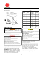
1
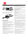
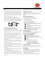
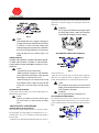
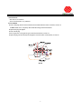
Operator’s Manual
R
Commercial / Residential
28″Mower
●
Service Information
●
Mower Operation
●
Adjustments & Repairs
●
Warranty
Worldlawn Power Equipment, Inc.
Industrial Park 2415 Ashland Ave.
Beatrice, NE 68310
Toll Free Number: 1-800-267-4255
Service Information
WORLDLAWN 28” COMMERCIAL RESIDENTIAL MOWER
SERVICE AND REPAIR PARTS INFORMATION
If you have questions, problems, or need an Operator’s or
Parts Manual, please contact your local Worldlawn
authorized dealer or call the Factory. When calling or writing,
Factory specified replacement parts for your Mower are
please provide the Model and Serial Number of your Mower.
available from either your local Worldlawn authorized dealer
WORLDLAWN POWER EQUIPMENT, INC.
or by calling the Factory.
Phone: …………………………………… (402)228-4255
For engine information, contact your nearest authorized
Fax: ……………………………………… (402)223-4103
Engine Service Dealer. The Engine Warranty is covered by
E-mail: www.worldlawnpowerequip.com
the Engine Manufacturer’s Limited Warranty.
Some of the pictures will vary between models but they
Record
generally depict similar information.
Model No.
MODEL NUMBERS 28” MOWERS
MODEL
WY28…
WY28B…
Cutting Height
1.5’’-3’’
2’’-4’’
Serial No.
Table of Contents
TABLE OF CONTENTS
SAFETY INFORMATION
Equipment Safety and Training……………..………………………………………...
General Safety Instructions…………………………………………………………...
Unpacking & Initial Assembly………………………………………………………..
Preparation to Mow…………………………………………………………………...
Operating the Mower ……………………………………………………………........
Maintenance and Storage………………………………………………………..........
1
1
1
2
2
3
MOWER OPERATION
Initial Run Procedures ………………………………..... ……………………........
Mower Operation………………………………..... ……………………....................
Before Starting the Engine……………………..... ……………………......................
Starting the Engine …………………………………………………….……..……..
Blade Drive……………………………………………………………………………
Wheel Drives………………………………………………………………………….
Stopping the Mower……………………………………………………………..........
3
3
3
3
3
4
4
ADJUSTMENTS AND REPAIRS
Mower Deck Adjustments……………………………………………………………
Mower Deck Belt Adjustments ………………………………………………………
Transmission Drive Belt Adjustments ……………………………………………….
Wheel Drive Belt Adjustments……………………………………………………….
Blade Replacement……………………………………………………………………
2-4″Blade Drive Belt Replacement…………………………………………………
1.5-3″Blade Drive Belt Replacement ………………………………………………
Synchronous Belt Replacement………………………………………………………
Transmission Drive Belt Replacement………………………………………………..
Blade Brake Pad Replacement………………………………………………………..
Wheel Drive Belt Replacement………………………………………………………
Rear Wheel Tube Replacement ………………………………………………………
Drive Control Adjustments……………………………………………………………
Shift Control Rod Adjustment………………………………………………………...
Transmission Case Replacement……………………………………………………..
Electrical Schematic ………………………………………………………………….
Service Instructions for Transmission ………………………………………………..
4
4
4
5
5
5
5
5
5
6
6
6
6
6
7
8
9
ACCESSORY
Grass Catcher …………………………………………………………………………
10
SERVICE BATTERY
Service Battery…………………………………………………………….. . . . . . . .
Connecting the Negative Battery Cables…………………………………….. . . . . .
Check Battery Charge…………………………………………………………….. . .
10
10
11
LIMITED WARRANTY
Warranty Information…………………………………………………………………
12
RULES FOR SAFE OPERATION
LOOK FOR THIS SYMBOL TO POINT OUT IMPORTANT
SAFETY PRECAUTIONS. IT MEANS ATTENTION!
BECOME ALERT! YOUR SAFETY IS INVOLVED.
EQUIPMENT SAFETY AND TRAINING
● READ THE OPERATOR’S Manual Carefully. Be thoroughly
familiar with the controls and the proper use of the Mower.
● NEVER allow children to operate or ride on the Mower. Do not allow
adults to operate the Mower without proper instruction.
● KEEP the area of operation clear of all bystanders, particularly small
children and pets.
● DO NOT operate the Mower if under the influence of alcohol,
medication, or when tired or ill.
Your mower was built to the highest standards in the industry;
DANGER
The signal word “DANGER” denotes that an extremely
hazardous situation exists on or near the machine that
could result in high probability of death or irreparable
injury if proper precautions are not taken.
WARNING
however, the prolonged life and maximum efficiency of your mower
depends on you following the operating, maintenance, and adjustment
The signal word “WARNING” denotes that a hazard
instructions in this manual.
exists on or near the machine that can result in injury or
We encourage you to contact your dealer for repairs. Worldlawn dealers
death if precautions are not taken.
are informed of the latest methods to service this mower and provide
prompt and efficient service .
CAUTION
A replacement operator’s manual is available from your dealer or by
contacting Worldlawn Power Equipment, Inc. Industrial Park 2415
The signal word “CAUTION” is a reminder of safety
Ashland Avenue Beatrice, NE 68310.
practices on or near the machine that could result in
E-mail: www.worldlawnpowerequip.com. Please indicate the complete
personal injury if proper precautions are not taken.
model and serial number of your Worldlawn mower.
Use of other than original Worldlawn replacement parts will void the
UNPACKING & INITIAL ASSEMBLY
warranty.
·Open crate.
The “Right” and “Left”, “Front” and “Rear” of the machine are
·Remove loose parts (i.e., Operator’s manual, etc) from crate.
referenced from the operator’s perspective when in the normal operating
·Remove unit from crate, check crate thoroughly for loose parts.
position and facing the forward travel direction.
·Attach the handlebars with two M8×50 Hex Hd bolts, two M8×25
GENERAL SAFETY INSTRUCTIONS
bolts, four M8 locknuts, and four M8 washers on each side as shown in
·Read this operator’s manual and instructions furnished with
FIG 1.
attachments. Perform only those maintenance procedures described in
this manual. If major repairs are ever needed or assistance is desired,
contact an authorized Worldlawn dealer. To ensure optimum
performance and safety, always purchase genuine Worldlawn
replacement parts and accessories.
·FAILURE
TO
FOLLOW
THESE
INSTRUCTIONS
OR
INCORRECTLY OPERATING THE MOWER, COULD RESULT
IN SERIOUS PERSONAL INJURY.
This symbol means “Attention! Become Alert!”
FIG 1
1
·Each of the control rods must be connected as shown in FIG 2. Follow
● Know the controls and how to stop quickly.
the instructions to properly adjust each of the controls.
● Do not allow children under fourteen years old to operate the mower.
Do not allow adults to operate the mower without proper instruction.
● The owner/user can prevent and is responsible for accidents or injuries
occurring to themselves, other people, or property.
OPERATING THE MOWER
engine as shown in FIG 3 and in the engine operator's manual.
● ALWAYS wear safety goggles or safety glasses with side shields
when operating the Mower.
● DO NOT change the Engine Governor setting or overspend the
engine.
● DO NOT put hands or feet near or under rotating parts. Keep clear of
the discharge opening at all times.
● Disengage the blades and wait for them to stop before crossing gravel
·Install the discharge chute as shown in FIG 4.
drives, walks, or roads.
FIG 2
·Route the throttle control cable through the rear shield and attach to the
● MOW only in daylight or in good artificial light.
Always run the Engine at the fast speed setting for best mowing
performance.
●If the cutting blades should strike a solid object or the equipment
should start to vibrate abnormally, stop the engine, disconnect the spark
plug wire, and check immediately for the cause. Vibration is generally a
warning of trouble. Check the mower for damaged or defective parts.
Repair any damage before starting the engine or operating the mower
deck. Be sure the blades are in good condition and the blade bolts are
FIG 3
tight.
● STOP the Engine whenever you leave the Mower or during cleaning,
SAFETY OPERATION
repairing, or inspecting. Make certain the Blades and all moving parts
PREPARATION TO MOW
have stopped. Disconnect the spark plug wire and keep the wire away
● Remove all debris or other objects that might be picked up and thrown
from the plug to prevent accidental starting.
by the blades. Keep all bystanders away from the mowing area.
● MOW across the face of slopes; never up and down. Exercise
extreme caution when changing direction on slopes. Do not mow on
slopes (with an incline of more than 15°). Exceeding the maximum
safe operating angle may cause tipping and loss of Mower control.
●The discharge chute must always be installed and in the down position
● DO NOT operate the Mower when barefoot or wearing open sandals.
Always wear appropriate footwear.
● CHECK the fuel before starting the engine. Do not fill the gasoline
tank indoors or when the engine is running. Wait until the engine has
been allowed to cool for several minutes before filling with gasoline.
Clean up any spilled gasoline before starting the engine.
● KEEP the Blade Drive Lever in the disengaged position and shift the
Transmission into neutral before starting the engine.
Never make a height adjustment or any other Mower adjustment while
the engine is running.
● NEVER operate the Mower in wet grass. Always be sure of your
footing; keep a firm hold on the handles and walk; never run.
● Do not smoke while handling gasoline.
except when the optional grass catcher or mulching shield is properly
installed. If the discharge area should plug, shut the engine off and wait
for all movement to stop before removing the obstruction.
●Do not touch the engine or muffler while the engine is running or a
short time after it has stopped. These areas could be hot enough to cause
a burn.
●The engine should be started with the neutral latches in the neutral lock
”
● Fill the tank outdoors and up to approximately 1 (25 mm) below the
bottom of the filler neck.
● Keep all shields, safety devices, and decals in place. If a shield, safety
position, the blades disengaged, the transmission in neutral, and the
device, or decal is defective or damaged, repair or replace it before
Exhaust fumes are hazardous and could possibly be deadly.
operating. ALSO, CHECK ALL NUTS, BOLTS, AND SCREWS
●Using the mower demands attention. To prevent loss of control:
FOR PROPER TIGHTNESS, TO ASSURE THE MOWER IS IN
A. Watch for holes or other hidden hazards.
operator’s presence levers released.
●Do not run the engine in a confined area without adequate ventilation.
SAFE OPERATING CONDITION.
B. Do not drive close to a drop-off, ditch, creek bank, or other hazard.
2
C. Reduce speed when making sharp turns and when turning on
● Drain and refill the transmission oil yearly- use one pint of SAE30.
hillsides.
● Grease Fittings are provided on important parts requiring lubrication.
● Do not operate the mower under the influence of alcohol or drugs.
● Before leaving the operator position or leaving the mower unattended,
MOWER OPERATION
shift the transmission into neutral, place the neutral latches in the neutral
CAREFULLY READ AND UNDERSTAND ALL SAFETY
lock position, and release the Blade Drive Lever. Shut the engine off.
INSTRUCTIONS BEFORE ATTEMPTING TO OPERATE THE
● Shut the engine off and wait until the blades come to a complete stop
MOWER.
before removing the grass catcher.
INITIAL RUN PROCEDURES
● Never raise the mower deck while the blades are rotating.
·Check the belts for proper tension at 2, 4, and 8 hours.
● Always park the mower and/or start the engine on a level surface.
·Check the steering control rods for neutral adjustment .
● Do not pass or stand on the grass discharge side of any mower while
·Check the tires for proper pressure.
the engine is running. Stop operation when another person approaches.
Drive wheels: 30 PSI (210kPa)
FIG 4.
·Check for loose hardware. Tighten as needed.
·Check the safety switches for proper adjustment:
The engine will crank, but not start, if the mower is not
in neutral.
The engine will crank, but not start, if the blade drive
FIG 4
MAINTENANCE AND STORAGE
lever is engaged.
Allow only trained personnel to service the mower.
and the blade drive lever is disengaged.
The engine should start if the transmission is in neutral
● Disconnect the spark plug wire from the spark plug to prevent
·Check to make sure that all the fittings have been lubricated.
accidental starting of the engine when servicing, adjusting, or storing the
MOWER OPERATION
mower.
READ AND UNDERSTAND THE SAFETY INSTRUCTIONS
● If the mower must be tipped to perform maintenance or adjustment,
BEFORE ATTEMPTING TO OPERATE THE MOWER
remove the battery and drain the gasoline from the fuel tank.
BEFORE STARTING THE ENGINE
● To reduce potential fire hazard, keep the engine free of excessive
Check oil level in the engine.
grease, grass, leaves, and accumulations of dirt.
Fill the fuel tank with clean, lead-free, gasoline.
● Be sure the mower is in safe operating condition by keeping nuts,
Open the fuel line shut-off on the bottom of the fuel
bolts, and screws tight. Check the blade bolts and nuts frequently to be
tank.
sure they are tight.
NOTE:
● If the engine must be running to perform a maintenance adjustment,
·The transmission must be in neutral.
keep hands, feet, clothing, and other parts of the body away from the
·The blade drive lever must be disengaged.
blades and other moving parts.
·Operator presence levers must be released.
● Do not overspend the engine by changing governor settings. To be
·Steering levers must be in the neutral lock position.
sure of safety and accuracy, have an authorized dealer check maximum
START THE ENGINE
engine speed with a tachometer.
When starting a cold engine, move the throttle control to choke position.
● The engine must be shut off before checking the oil or adding oil to
When restarting a warm engine, move the throttle control to the
the crankcase.
mid-way position.
● Allow the engine to cool before storing the mower in any enclosure
BLADE DRIVE
such as a garage or storage shed.
Squeeze and hold the operator presence levers (engaged). Push the
● Always store gasoline in a safety-approved, red container.
mower blade drive lever forward to engaged position. The blades will
● Caution must be taken while maintenance is being done to battery.
rotate at high speed. Pull the mower blade drive lever backward to
Battery contains corrosive acid which can burn your skin and clothing.
disengaged position to stop the blades. FIG 5.
● Keep battery away from fires. Short circuit of battery can cause
THE BLADE TIP SPEED ON 28’’ IS 14,240 FEET PER MINUTE
explosion.
3
deck; align holes and release pins in desired register mark. Repeat on
opposite side. Ensure the readings of all four register marks are the
same. FIG 6.
WARNING:
Be sure engine is off and blade is fully stopped to adjust
the cutting height. Failure to follow these instructions
could result in personal injury or mower damage.
FIG 5
NOTE:
When the blade drive lever is engaged or disengaged, a
squealing sound from the underside of the mower deck
is normal. It is caused by the blade rotating speed
suddenly changing. Slowly push the mower blade drive
FIG 6
MOWER DECK BELT ADJUSTMENTS
lever forward to engaged position. For best mower life,
engage the blade drive lever with the engine at 3/4
throttle.
WHEEL DRIVES
SQUEEZE THE STEERING LEVERS WITH BOTH HANDS
TO KEEP THE NEUTRAL LATCHES IN THE NEUTRAL
LOCK POSITION; MOVE GEAR SHIFT LEVER TO 1, 2, OR 3
POSITION.
NOTE:
FIG 7
·Top speed is only used for transportation.
·While squeezing the steering levers with both hands,
·Remove the belt cover.
release right and left neutral latches; release right and
·Adjust the mower deck belt using a belt tension gauge. Engage the
left steering lever to make the mower travel.
blade drive lever. Adjust the tension by tightening or loosening the
·When the steering levers are released, the mower will
locknut. The belt should move 1/4” with 10 pounds of pressure. FIG 7
travel straight. To make a right turn, squeeze the RH
NOTE:
steering lever. To turn left, squeeze the LH steering
Due to initial belt stretch and to prevent the belt from
lever.
slipping, check this adjustment after the first 2 hours, 4
STOPPING THE MOWER
hours, and 8 hours of operation.
To stop, squeeze both the steering levers, lock the neutral latches, and
WARNING:
shift the transmission into neutral.
Be sure engine is off before removing belt cover.
NOTE:
TRANSMISSION DRIVE BELT
Push the gear shift lever forward to increase speed.
The transmission drive belt is on the underside of the engine frame
The mower must be at full stop before decreasing
weldment. Adjust the belt so that the belt moves 1/4” with 10 pounds of
speed.
pressure. Adjust the tension by moving transmission drive idler pulley.
ADJUSTMENTS AND REPAIRS
FIG 8.
MOWER DECK ADJUSTMENTS
·Due to the many cutting conditions that exist, it is necessary to adjust
the cutting height. The cutting height can be adjusted from 1.5” to 3”
(WY28B: from 2” to 4”) in 0.5” increments by changing the height of
the mower deck.
FIG 8
·To adjust the mower deck height, hold handle and pull J-pins on side of
4
WARNING:
WARNING:
Be sure engine is off before removing belt cover
Shut off engine and disconnect the spark plug wire
and replacing blades.
before adjusting the belt.
2-4″BLADE DRIVE BELT REPLACEMENT
WHEEL DRIVE BELT ADJUSTMENTS
Remove the belt cover. Loosen locknuts of the blade pulley belt guard
bracket on the mower deck and rotate the belt guard bracket outward at
an angle. Loosen locknuts of the belt guard on the belt guard fixed seat
on the mower deck. Loosen nuts of the belt guard brackets on the idler
pulleys and remove the belt guards from holes. Loosen bolts of the LH
belt guard bracket beside engine pulley on the engine frame and nuts of
the long bolt on the RH belt guard bracket. Rotate the guards upward at
FIG 9
an angle and install new belt. Reinstall guards and guard brackets. Keep
Adjust the wheel drive belts on either side of the mower when the
the blade drive lever in the engage position and tighten the belt. Give a
mower pulls to one side or the other. If it pulls to the left, add tension to
1/8"(3mm) clearance between the guards and pulleys. Tighten all the
the belt on the right side of the mower. If it pulls to the right, adjust the
nuts and bolts. Check the belt for proper tension. Reinstall the belt cover.
belt on the left side of the mower. FIG 9
FIG 12
BLADE REPLACEMENT
1.5-3″BLADE DRIVE BELT REPLACEMENT
Remove belt cover. Remove blade bolts, washers, and locknuts. Replace
Remove the belt cover. Loosen locknuts of the blade pulley belt guard
all parts in proper order. Be sure blade coupling above the blade and the
bracket on the mower deck and rotate the belt guard bracket outward at
flats in blade are aligned with flats on the blade spindle. Torque to 66±
an angle. Loosen locknuts of the belt guard on the belt guard fixed seat
13ft-lb (90±18N-M). Be sure that both blades are positioned equally and
on the mower deck. Loosen bolts of the LH belt guard bracket beside
perpendicular to each other. FIG 10, FIG 11
engine pulley on the engine frame and nuts of the long bolt on the RH
belt guard bracket. Rotate the guards upward at an angle and install new
belt. Reinstall guards and guard brackets. Keep the blade drive lever in
the engage position and tighten the belt. Give a 1/8"(3mm) clearance
between the guards and pulleys. Tighten all the nuts and bolts. Check the
belt for proper tension. Reinstall the belt cover. FIG 12-1
NOTE:
All locknuts on belt guards (and brackets) must be
securely tightened.
SYNCHRONOUS BELT REPLACEMENT
Remove the belt cover. Remove blade drive belt from the blade pulley.
FIG 10
Remove linking plate. Remove locknut and spacer from the RH blade
bolt, and remove synchronous belt and synchronous pulley. Replace all
parts in proper order. FIG 12
Replace synchronous belt every 200 hours.
WARNING:
Be sure that both blades are perpendicular to each
other while installing. It could otherwise result in
serious mower damage. FIG 11
TRANSMISSION DRIVE BELT REPLACEMENT
Loosen the bolts of the LH belt guard bracket by the engine pulley and
nuts of the long bolt on the RH belt guard bracket. Rotate the belt guard
FIG 11
brackets on both sides at an angle. Remove the blade drive belt from the
engine pulley. Loosen the locknut of transmission drive idler pulley and
5
move the transmission drive idler pulley. Remove the old belt and install
Remove rear Hex Hd Bolt securing Belt Guard and loosen front Hex Hd
new belt. Replace all parts in proper order. Adjust the belt following
Bolt securing Belt Guard. Pivot guard on Front Hex Hd Bolt. Squeeze
proper procedure. Tighten all the locknuts. FIG 12.
Steering Lever to loosen Idler Pulley and remove the wheel drive belt
NOTE:
from Transmission Output Pulley. Remove the belt from the wheel drive
All locknuts on belt guards must be securely tightened.
pulley on drive wheel. Install new belt and replace all parts in proper
BLADE BRAKE PAD REPLACEMENT
order. Adjust the belt following belt adjustment procedures. FIG 13
Remove belt cover. Move blade brake arm assembly out of the way and
REAR WHEEL TUBE REPLACEMENTS
remove hardware securing blade brake pad. Install new pad, center the
To replace tube, remove tire and rim assembly from the wheel hub
pad in the blade pulley groove, and re-tighten nuts. Test operation of the
weldment. Remove bolts from tire and rim assembly, split the rim,
blade brake system to see that the blade brake stops blade rotation within
remove old tube, and install new tube. Reinstall drive wheel assembly in
3 seconds. FIG 12
proper order.
DRIVE CONTROL ADJUSTMENTS
The drive control is a system of interconnected linkages which have
steering and braking functions. One steering lever function is neutral
latch lock position or neutral latch unlock position. When steering levers
are in neutral lock position, the power is disengaged. To brake, squeeze
both brake levers and operator presence control rod on the mower.
Adjusting control rod: Remove hair pin on the top of control rod, pull
out the control rod from steering lever, turn the control rod so that the
length of two control rods is same, and reinstall all parts in proper order.
FIG 12
Adjusting brake lever: Loosen or tighten locknut at the bottom of
brake lever to adjust the length of the brake lever. See FIG 14
FIG 12-1
FIG 14
NOTE:
Shut off engine and disconnect the spark plug wire
SHIFT CONTROL ROD ADJUSTMENTS
before removing belt cover.
WHEEL DRIVE BELT REPLACEMENT
Move Shift Control Rod into neutral position. Handle should compress
pressure switch button down 5mm, otherwise rod length should be
adjusted. To change rod length, remove cotter pin from upper Shift
Control Rod Assembly. Remove rod from lever bracket hole. Rotate rod
until desired length is achieved to cause switch to compress correctly.
Reinstall rod into lever bracket hole and add cotter pin. FIG 15
FIG 13
6
TRANSMISSION CASE REPLACEMENT
When replacing transmission case, remove the M6x16 bolts which link
left and right connecting pads to output axis; then loosen inner shaft hex
bolts. Remove lower hex bolts (3300106), which link transmission case
and console frame. Remove bolt which connects shift arm weldment on
top of transmission case to shift rod arm assembly. Remove the bolt
(3300198) of transmission input pulley. Remove pulley and then remove
the belt. Install new transmission case back into position. Reinstall bolts
of left and right connecting pads of transmission case to drive output axis;
leave bolts loose. Install and tighten bolts (3300106) which link
LUBRICATION SCHEDULE
FIG 16
transmission case and console frame. Install and tighten shift arm
weldment bolt. Reinstall transmission belt and pulley and tighten pulley
bolt (3300198).
Finally, tighten left and right connecting pad M6×16 bolts and inner
shaft hex bolts. FIG 17
FIG 17
FIG 15
7
ELECTRICAL SCHEMATIC
WIRING HARNESS DIAGRAM
8
SERVICE INSTRUCTIONS FOR TRANSMISSION
Service Interval
First-time service: 80 hours
Service time thereafter: every 300 hours
Service Method
·Remove drain plug from the back of transmission and drain lubricant oil into a container, see FIG 18.
Caution: Make sure to completely drain all the lubricating oil from transmission.
·Replace drain plug and tighten.
·Remove the fill plug.
·Pour 0.50 pt(0.25L) #18 hyperbolic gear oil into the transmission, see FIG 18.
·Replace fill plug into the transmission and tighten. Clean the surface of transmission, see FIG 18.
FIG 18
9
GRASS CATCHER & COUNTER-WEIGHT
Chart 1
Grass catcher: FIG 19
Model:
WY28-NGC
Capacity:
80 Liters(2.2 Bushels)
Voltage
Percent
Maximum
Charging
Reading
Charge
Charger
Interval
Settings
12.6 or
100%
greater
12.4-12.6
75%-100%
16Volts/7
No charging
amps
Required
16Volts/7
30 Minutes
amps
12.2-12.4
50%-75%
16Volts/7
1 Hour
amps
12.0-12.2
25%-50%
14.4Volts/4
2 Hours
amps
11.7-12.0
0-25%
FIG 19
14.4Volts/4
3 Hours
amps
11.7 or less
0%
14.4Volts/4
6 Hours or
amps
more
SERVICE BATTERY
Battery posts, terminals, and related accessories contain lead
compounds,
chemicals
known
to
cause
cancer
POTENTIAL HAZARD
and
·If the ignition is in the “ON” position, there is potential for
reproductive harm.
sparks and engagement of components.
The machine is shipped with a filled lead acid battery
WHAT CAN HAPPEN
without protection.
·Sparks could cause an explosion or moving parts could
Unhook seat latch and tilt seat to gain access to the battery.
accidently engage causing personal injury.
HOW TO AVOID THE HAZARD
POTENTIAL HAZARD
· Be sure ignition switch is in the “OFF” position before
·Charging the battery may produce explosive gasses.
charging the battery.
WHAT CAN HAPPEN
·Battery gasses can explode causing serious injury.
CONNECTING THE NEGATIVE
BATTERY CABLES:
HOW TO AVOID THE HAZARD
·Keep sparks, flames, and cigarettes away from battery.
Note: If the positive cable is also disconnected, connect the
Ventilate when charging or using battery in an enclosed space.
positive (red) cable to the positive battery terminal first, then
Check the voltage of the battery with a digital voltmeter.
the negative (black) cable to the negative battery terminal.
Locate the voltage of the battery in the table below and
Slip insulator boot over the positive terminal.
charge the battery for the recommended time interval to
Note: If time does not permit charging the battery, or if
bring the charge up to a full charge of 12.6Volts or greater.
charging equipment is not available, connect the negative
IMPORTANT: Make sure the negative & positive
battery cables and run the vehicle continuously for 20 to 30
battery cables are connected correctly and the battery
minutes to sufficiently charge the battery.
charger used for charging the battery has an output of 16
volts and 7 amps or less to avoid damaging the battery.
10
·Battery contains sulfuric acid. Avoid contact and always
shield eyes, face, skin, and clothing from battery. Cigarettes,
flames, or sparks could cause battery to explode.
·Do not charge, use booster cables, or adjust post connection
without proper training.
·If battery acid comes in contact with skin or eyes, flush with
water and call a physician immediately.
·Keep out of reach of children.
CHECK BATTERY CHARGE
Service Interval: Monthly
Allowing batteries to stand for an extended period without
recharging them will result in reduced performance and
service life. To preserve optimum battery performance and
life, recharge them in storage when the open circuit voltage
drops to 12 Volts.
Note: To prevent damage due to freezing, battery should be
fully charged before putting away for winter storage.
a) Check the voltage of the battery with a digital voltmeter.
Locate the voltage reading of the battery in the table (See
chart 1) and charge the battery for the recommended time
interval to bring the charge up to a full charge of 12.6 Volts
or greater.
IMPORTANT: Make sure the negative & positive battery
cables are connected correctly and the battery charger used
for charging the battery has and output of 16 volts and 7
amps or less to avoid damaging the battery.
11
LIMITED WARRANTY
WORLDLAWN POWER EQUIPMENT, INC
28” MOWER
Worldlawn Power Equipment, Inc, (“Worldlawn”) warrants
that the Worldlawn 28” Mower (“Mower”) will be free from
defects in material and workmanship for a period of one year
commercial from the original date of purchase. During the
warranty period, Worldlawn will repair or replace, at its
discretion, any Mower or part thereof which is found to be
defective in material or workmanship. This warranty
specifically excludes wear items, including but not limited to
belts, blades, and tires. This warranty also specifically
excludes parts covered by another manufacturer’s warranty,
which parts are covered only by that manufacturer’s
warranty.
Worldlawn’s sole responsibility with any claim made under
this warranty is limited only to repairing or replacing the
mower or a defective part thereof, and no claim of breach of
warranty shall be cause for rescission, cancellation, or
voiding the contract of sale of the Mower.
This warranty does not extend to any Mower or part thereof
which has been misused, neglected, damaged, abused, not
properly installed or maintained, altered, or which has been
operated in any way contrary to the operating instructions as
specified in the Owner/Operators Manual. This warranty
does not extend to any repair or replacement made necessary
by normal use . This warranty does not extend to the engine
which is warranted separately by the engine manufacturer.
This limited warranty extends only to the original retail
purchaser (“Owner”) of a Mower. It is not transferable. This
warranty extends only to those Mowers purchased for
private residential and commercial use .
THE WARRANTY EXPRESSED HEREIN IS IN LIEU
OF OTHER WARRANTIES, EXPRESSED OR IMPLIED,
INCLUDING, WITHOUT LIMITATION, ANY IMPLIED
WARRANTY OR MERCHANTIBILITY OR FITNESS
FOR A PARTICULAR USE AND IS IN LIEU OF ANY
AND ALL OTHER OBLIGATIONS OR LIABILITY ON
WORLDLAWN’S PART.
Proof of purchase will be required to substantiate all
warranty claims. All warranty work must be performed by
an authorized Worldlawn Dealer. Any work done on or to the
Mower by anyone other than an authorized Worldlawn
Dealer, including the original purchaser, voids all provisions
of this warranty except those provisions which limit
Worldlawn’s liability (as set forth below).
UNDER ANY AND ALL CIRCUMSTANCES,
WORLDLAWN’S TOTAL LIABILITY TO OWNER
FOR ANY AND ALL CLAIMS, LOSSES, OR
DAMAGES, INCLUDING LOSS OF PROFITS,
ARISING OUT OF ANY CAUSE WHATSOEVER,
WHETHER BASED IN CONTRACT, NEGLIGENCE,
OR OTHER TORT, STRICTLIABILITY, BREACH OF
WARRANTY OR OTHERWISE, SHALL IN NO EVENT
EXCEED THE PURCHASE PRICE OF THE MOWER .
IN NO EVENT SHALL WORLDLAWN BE
RESPONSIBLE FOR SPECIAL, INCIDENTAL,
CONSEQUENTIAL, OR EXEMPLARY DAMAGES.
Any Mower or part thereof which, at Worldlawn’s sole
discretion, is deemed defective shall be repaired or replaced ,
at Worldlawn's discretion, without charge for parts or labor.
To take advantage of this warranty, the Mower must be
returned to an authorized Worldlawn Dealer within the
warranty period. The cost of delivering the Mower to the
authorized Dealer and return delivery shall be the
responsibility of the Owner.
12
Notes:
Notes:
R
Worldlawn Power Equipment, Inc.
Industrial Park 2415 Ashland Ave. Beatrice, NE 68310
Phone: (402) 228-4255
Fax: (402) 223-4103
www.worldlawnpowerequip.com
Form No. 28102-201111