1
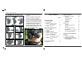
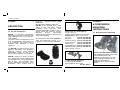
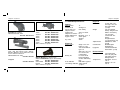
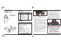
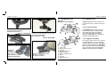
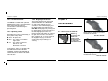
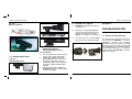
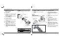
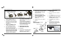
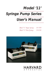
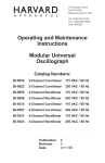
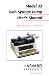
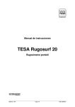
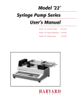
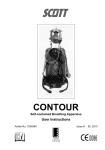
PYSER-SGI LIMITED
PNP-MC Pocket Scope
Operator’s Manual
YSER-SGI LIMITED
Fircroft Way, Edenbridge, Kent United Kingdom, TN8 6HA
Telephone: +44 (0) 1732 864111
Facsimile: +44 (0) 1732 865544
Email: [email protected]
www.pyser-sgi.com
NSN: 5855-99-855-1401
560 - 007 - 51
100/03/09
Chapter 5. Accessorie Mounting
5.3 PNP-MC with head mount / helmet
mount fitting guide
1.
2.
WARNING
3.
LIMITED WARRANTY
This product contains an image
intensifier tube.
The manufacturer of this
POCKET SCOPE, has provided a limited
warranty to the original purchaser. It was
attached to the manufacturer’s terms and
conditions of sale.
Permanent damage to the tube may result if
the product is used in normal room
illumination or bright ambient light. Do not
direct it at a bright light source such as the
sun, street or vehicle lights or over an
extended period toward another bright light
source or stationary scene which could lead
to permanent damage to the image
intensifier tube.
4.
5.
6.
7.
8.
9.
Attach monocular to the mount with
thumbscrew A
Depress plunger B to lift monocular
into the vertical position (where it will
automatically shut off)
Adjust pitch setting of the monocular
with thumbscrew C
Adjust height setting of the monocular
with thumbscrew D
Adjust lateral setting of the monocular
with thumbscrew E
Adjust forward/backward setting of the
monocular with thumbscrew F
For rapid removal of the monocular,
fully loosen thumbscrew F, depress
plunger G and slide the assembly off
its mounting slide away from the face.
For safe stowage, press the lens cap,
when not in use, onto pin H.
For fine adjustment of pitch slacken
screws J move monocular to desired
attitude and re-tighten screws.
PNP-M - Operator’s Manual
21
Chapter 5. Accessorie Mounting
5.2 PNP-MC with switching mount
1.
2.
3.
4.
Fully unscrew thumb knob C to the
end stop
Remove the slider block assembly,
rotate its orientation accordingly
Re attach and tighten thumbscrew C
TIP to get maximum tightness, tighten
thumbscrew C whilst monocular is at
its maximum pitch travel (UP for R/H
& DOWN for L/H) then complete
tightening whilst turning knob C and
simultaneously rotating the monocular
into the desired pitch setting.
TABLE OF CONTENTS
Page
Chapter 1 Description
1.1 System description
1.2 Specifications
1.3 PNP-MC standard equipment
and accessories
1.4 PNP-MC main parts
Chapter 2 Operating Instructions
2.1 Battery installation
2.2 Operation
2.3 PNP-MC applications
2.4 PNP-MC operation with DSLR
and SLR cameras
2.5 PNP-MC operation with
video cameras / camcorders
2.6 PNP-MC operation with CCTV
cameras
Chapter 3 Troubleshooting
3.1 General
20
PNP-MC - Operator’s Manual
PNP-MC - Operator’s Manual
2
3
4-5
5-6
7
7
7
8
10
11
11
Chapter 4 Accessories
4.1 Accessories for PNP-MC
Relay Lens
Shuttered Eyeguard
HeadHarness
Helmet Mount
Bridge Kit
Weapon Mount
Anti-Mist
150mw Illuminator, IR LED
Lanyard
Camcorder/Camera Adaptor
Optical Module
Camera lens to C-mount Adaptor
12v Car Cigarette Plug/Lead
15
15
15
15
16
16
16
17
18
18
18
18
18
19
19
Chapter 5 Accessorie(s) Mounting
Instructions
5.1 Dual Monocular Mounting
5.2 PNP-MC with Switching Mount
5.3 PNP-MC with Head Mount/ Helmet
mount fitting guide
19
19
20
21
13
14
1
Chapter 1. Description
Chapter
Chapter 5. Accessorie Mounting
1
DESCRIPTION
1.1 System description
PNP-MC is a powerful, multi-purpose,
lightweight, pocket-sized monocular night
scope utilising C-mount CCTV lenses for
extra flexibility.
The pocket scope is designed to be used
either as a stand-alone night vision device
or in combination with a wide variety of
standard video, still-photo or CCTV
equipment.
insufficient - especially effective inside
buildings etc.
Special purpose adaptors enable the
PNP-MC to be mounted onto a wide
variety of SLR and video cameras
(including CCTV cameras). Thus,
standard photographic equipment can be
quickly turned into powerful, effective
night-time
devices,
dramatically
enhancing your intelligence gathering and
observation capability.
As a stand-alone night scope, PNP-MC is
small and lightweight enough to be
unintrusive. It may be easily hand-held.
ACCESSORIE(S)
MOUNTING
INSTRUCTIONS
Camera lens to C-mount adaptor
(see # 2 of 2.4.3)
Attaches original camera lens directly to
PNP-MC body in place of CCTV lens
T2 lenses
Part No: 589-840-403
M4 lenses
Part No: 589-840-404
Canon FD lenses Part No: 589-840-405
Pentax K lenses
Part No: 589-840-406
Nikon lenses
Part No: 589-840-407
Minolta MD lenses Part No: 589-840-409
Olympus OM lenses Part No: 589-840-410
5.1 Dual monocular mounting
Others available on request
The PNP-MC is a powerful tool for covert
night-time observation and intelligencegathering purposes using standard
photographic media, as well as an
effective aid to night-time field missions.
PNP-MC employs an image intensifier
tube characterized by high resolution and
a clear, bright image. It is equipped with its
own IR LED - type illuminator, which
provides additional, close-range covert
illumination, when ambient light is
2
Chapter 5
12v Car Cigarette Plug/Lead
2 outputs (needs 560-012),
powers PNP-MC from vehicle
Part No: 560-011
PNP-MC - Operator’s Manual
PNP-MC - Operator’s Manual
ATTACH THE TWO MONOCULARS TO
THE BINOCULAR MOUNT USING THE
TWO THUMBSCREWS. THE
BINOCULAR CAN ATTACH TO THE
HEAD & HELMET MOUNTS IN THE
SAME WAY AS A SINGLE
MONOCULAR ON ITS SWITCHING
MOUNT.
19
Chapter 4. Accessories
Chapter 1. Discription
1.2 PNP-MC Specifications
Dimensions
Optical
Camcorder/Camera Adaptor
Anti-Mist for eyepiece
NSN 5855-99-341-1382
Part No: 560-007-010
30mm
30.5mm
35mm
49mm
52mm
58mm
72mm
Part
Part
Part
Part
Part
Part
Part
No:
No:
No:
No:
No:
No:
No:
589-840-300
589-840-305
589-840-035
589-840-042
589-840-041
589-840-058A
589-840-072
Others available on request
150mw Illuminator, IR LED
wide, mid and narrow FOV, 805nm.
Effective distance up to 280 metres with
Gen 2 and Gen 3 devices.
NSN 6650-99-731-1262
Part No: 583-340
Lanyard
Part No: 589-855
Optical Module (see # 4 of 2.4.3)
Attaches PNP-MC directly to camera body
Nikon
Part No: 589-840-400
Canon EOS Part No: 589-840-401
Pentax
Part No: 589-840-402
Others available on request
18
PNP-MC - Operator’s Manual
Magnification:
Field of view:
Focus range (m):
Objective focal
length (mm):
Objective F number:
Dioptre adjustment:
Eyepiece lens:
Eye relief
Physical
1x
40 Degrees
0.25-infinity
Weight
25mm C-mount
F1.4
Minimum +3 to - 6
25mm glass
aperture
27mm
Tripod mount
Electrical
Power source
Single 1.5 V ”AA”
battery or 1.5V
“AA” format lithium
type L91
(NSN 6135 01 333 6101)
or 1.2V”AA” size
rechargeable
Battery life:
In excess of 40
hours dependent
on tube and battery
type
IR on indicator
Red LED in eyepiece
Low voltage indicator Yellow LED in
eyepiece
PNP-MC - Operator’s Manual
Construction
Eyeguard
42 mm wide x 67
mm high x 114 mm
long (with folded
eyecup)
293 gms without
battery 308 gms with
lithium “AA” battery
318 gms with
commercial “AA”
battery
Weight includes
eyecup and lens cap
Standard ¼” UNC
thread
Moulded glass
filled polymer
Contoured soft fold
back rubber eyecup
Environmental
Waterproof
Temperature
Immersion proof
20m 1hr, (only with
waterproof lenses)
Nitrogen filled
Operation -45°C to
+55°C
Storage -51°C to
+65°C
3
Chapter 1. Description
Chapter 4. Accessories
1.3 PNP-MC Standard
equipment
and accessories
Fig. No. 1 - PNP-MC
standard kit
3
No.
Equipment
Qty
(1)
PNP-MC pocket scope
1
(2)
Eye guard
1
(3)
Carrying pouch
1
(4)
1.5V “AA” size battery
1
(5)
Operator’s manual
1
TABLE NO. 2
PNP-MC Optional accessories
Equipment
1
4
2
4
5. The PNP-MC can be removed, if necessary, from
the mount and the mount left on the weapon in
it’s correct position for next use.
TABLE NO. 1
PNP-MC Standard equipment list
Adaptors for SLR and DSLR cameras
Adaptors for Camcorders
CCTV (CCD) relay lens
Face-mask
Helmet mount
Lanyard
Various adaptors for Picatinny
or Weaver rails
Bridge Kit to convert to binoculars
Hard carrying case
Please see data sheet for full list of
accessories for PNP-MC
PNP-MC - Operator’s Manual
D
E
A
Interface for fitting PNP-MC to Picatinny rail
NSN 5304-99-574-0422
Part No: 589-997M
Instructions for use
1. Place the PNP-MC rail adaptor on to the Picatinny
(or Weaver) rail and lock it in position in a suitable
position on the rail using the over-centre lever “A”.
2. Position the PNP-MC on the adaptor so that it is
located both by the side support “B” and also by
the channels “C”. Use the finger knob “D” so that
the PNP-MC is fully and firmly tightened down onto
the adaptor.
3. Adjust the fore/aft position of the PNP-MC on the
adaptor for optimum eye relief by unscrewing the
two Allen bolts “E” and moving the upper part of
the adaptor into the best position for the firer. It is
essential that two bolts are used and are firmly
tightened. One bolt is not sufficient.
4. If necessary, to optimise eye relief, reposition the
entire mount on the Picatinny rail by using the
over-centre lever.
PNP-MC - Operator’s Manual
6. Remember to use day sights in front of the
PNP-MC, not behind it between the firer and the
PNP-MC and that any day sight with an
illuminated aiming mark must be “Night Vision
Compatible”. The intensity of the aiming mark
must be turned down to the minimum otherwise
a burn mark on the image intensifier tube will
result.
B
C
N.B. Although PNP-MC can be used
on head/helmet and weapon mounted
applications, this is not advised
except for emergency use, in view of
the standard lens not being
waterproof nor resistant to recoil
shocks of weapons.
PNP-M is the recommended
product for those applications.
17
Chapter 4. Accessories
Chapter 1. Description
1.4.1 Objective lens
1.4 PNP-MC Main parts
Fig. No. 2
PNP-MC Parts description
Standard objective lens in a 25mm F1.4
C-mount lens. (Any C-mount lens can be
used).
6
5
Head Harness for left and right eye use
and accepts binocular bridge
NSN 6650-99-407-0566
Part No: 550-006/AM
16
For dual monocular mounting
please see chapter 5
for fitting instructions.
PNP-MC - Operator’s Manual
The PNP-MC utilizes a range of tubes
characterized by low weight and high
gain, which also reduces the dazzle
effect which normally occurs when
viewing a bright light source through an
image-intensifier night scope.
1
9
4
(1)
(2)
(3)
(4)
(5)
(6)
(7)
(8)
(9)
8
7
3
Bridge Kit
Bridge Kit
converts
two PNPMC’s
into binoculars
NSN 5340-99-934-5341
Part No: 560-007-008
2
Helmet Mount universal fitting for ballistic
helmets. for left and right eye use and
accepts binocular bridge
NSN 5340-99-812-6225
Part No: 550-006/HM
1.4.2 Image intensifier
Pocket scope
Objective lens “C” mount
Eye guard
Eyepiece (diopter ring)
Operating switch
Battery compartment cover
Mount
I.R. LED
Bright Light Sensor
PNP-MC - Operator’s Manual
1.4.3 Eyepiece assembly
The eyepiece has a 27mm eye relief and
a diopter adjustment of +3 to -6 diopter.
A flexible rubber eye guard can be folded
back to enable interfacing the PNP-MC to
35mm SLR and video cameras (including
CCTV cameras) using special-purpose
adaptors fitted to the same threading.
5
Chapter 1. Description
1.4.4 I.R. LED Illuminator
The PNP-MC is equipped with a built-in
I.R. LED-type illuminator which provides
additional, close-range covert illumination
when ambient light is insufficient.
The illuminator is activated using the
operating switch.
1.4.5 Operating switch
Operation of the scope is controlled by a
three-position rotary switch:
OFF - All power off.
ON
I.R
- The scope is on enabling
night vision.
- The scope is on and the
built-in I.R. LED
illuminator is activated.
Chapter 4. Accessories
1.4.6 Bright Light Protection
The image intensifier tube is protected
against bright lights by a Bright Light
Sensor. The PNP-MC can be switched
on, with caution and only for a few
seconds, in indoor artificial lighting, but
the Bright Light Sensor will switch the
PNP-MC off in daylight, only allowing it to
be switched back on when the light level
falls. This protection is in addition to the
internal bright light protection of the
image intensifier tube which only reduces
the gain and which does not switch the
tube completely off. It can be disarmed
for daylight training by covering the
sensor orifice with a small piece of
electrical tape to prevent daylight
entering.
Chapter 4
ACCESSORIES
4.1 Accessories for PNP-MC
Before any
accessories are
fitted to the
eyepiece, fold
back the eyecup
to expose the
mounting thread.
“FOR SAFETY, THE I.R. CAN ONLY BE
SWITCHED WHEN THE SWITCH KNOB
IS FIRMLY PULLED OUT BEFORE
TURNING” “A RED LIGHT SHOWS IN
THE EYEPIECE TO ALERT THE USER
TO THIS FACT”
Relay Lens for use with CCTV camera
NSN 5836-99-366-5780
Part No: 550-003F
Shuttered Eyeguard
NSN 6650-99-789-6513
Part No: 550-007
6
PNP-MC - Operator’s Manual
PNP-MC - Operator’s Manual
15
Chapter 3. Troubleshooting
Chapter 2. Operating Instructions
Table No. 4
General troubleshooting
2.1 Battery installation
Chapter 2
1)
No
Symptom
Cause
Probable
Actions
Corrective
1
No visible
image
a. Objective lens
cap has not
been removed.
b. Battery cover
loose.
c. Incorrect
Battery
polarity.
d. Weak Battery.
a. Remove cap.
e. Iris closed
2
3
Persistent
Image
Flickers.
Poor
image
quality
a. Faulty
intensifier
tube.
a. Dirty or fogged
objective lens.
b. Eyepiece out of
focus
14
b. Tighten cover.
c. Re-insert
Battery
correctly.
d. Replace
Battery
e.Open Iris
a. Send unit to
repair/
maintenance
facility.
a. Clean lens with lens
cleaning tissue.
If lens is internally
fogged, send unit to
repair/maintenance
facility
Adjust diopter ring
to bring picture into
focus
PNP-MC - Operator’s Manual
OPERATING
INSTRUCTIONS
2)
3)
CAUTION
4)
5)
The PNP-MC is a delicate
electro-optical
device - handle it with care!
Ensure operating switch is in
OFF position.
Open battery compartment cover by
unscrewing cap.
Insert battery into compartment, notice
the polarity marking (see Fig. No. 3).
Close battery compartment cover
A low battery warning indicator is built into
the PNP-MC which gives an amber glow
at the edge of the image when looking
through the eyepiece.
2.2 Operation
WARNING
Permanent damage to the PNP-MC
may result if the PNP-MC is used in
normal room illumination or bright
ambient light. Do not direct the
PNP-MC at a bright light source such
as the sun, street lights, vehicle
lights, or other bright light source,
otherwise permanent damage may
occur to the image intensifier tube.
PNP-MC - Operator’s Manual
1)
2)
3)
4)
5)
6)
Prior to use remove protective lens cap.
Turn the operating switch to ON.
Adjust eyepiece diopter until the sharpest
phosphor screen is obtained.
Adjust objective lens focus ring while
observing an object until the sharpest
image is obtained. - Repeat 3 if necessary
Ensure that the iris is open on the lens.
To activate the I.R. illuminator turn the
operating switch to ON, then pull
outwards and turn further to the I.R.
position. When the I.R. illuminator is
switched on a red LED warning glow can
be seen at the edge of the image when
looking through the eyepiece.
7
Chapter 2. Operating Instructions
Chapter 3. Troubleshooting
2.7 PNP-MC Lens options
Fig. No. 3
Battery installation
1)
PNP-MC is designed to accept any
C-mount lens.
2)
PNP-MC can accept photographic
lenses from most manufacturers by
using a camera lens to C-mount
adaptor. See chapter 4 Accessories.
3)
“Off-On-I.R.” switch
2.4 PNP-MC Operation with
DSLR/SLR cameras
(interchangeable lenses)
2.4.1 Installation
1)
2.3 PNP-MC Applications
2)
Fig. No. 5
PNP-MC Applications
3)
8
The camera lens to C-mount adaptor
ensures the iris is always fully open.
Chapter 3
TROUBLESHOOTING
3.1 General Troubleshooting
The following table presents faults which
may occur in the PNP-MC. In case of
malfunction, identify the matching
description under the Symptom heading
and carry out the corrective actions until
the fault disappears. If the fault cannot be
corrected by carrying out the specified
actions, transfer the PNP-MC to a repair/
maintenance facility.
Use any DSLR/SLR camera with it’s
lens set to 35-50mm focal length.
Load a high sensitivity film B/W
(400+1600 ASA) if the camera is a
film camera and set the camera
accordingly. Digital cameras should
be set at the highest ASA if option
available
Mount the DSLR/SLR adaptor to
the PNP-MC eyepiece, (after folding
back the eyeguard).
PNP-MC - Operator’s Manual
PNP-MC - Operator’s Manual
13
Chapter 2. Operating Instructions
2.6 PNP-MC Operation with
CCTV cameras
Chapter 2. Operating Instructions
Fig. No. 8
PNP-MC Installation on CCTV camera
5)
2.6.1 Installation
1)
2)
Mount the CCTV relay lens to the
PNP-MC eyepiece (after folding
back the eye guard).
Mount PNP-MC with relay lens to
the CCTV camera.
CCTV CAMERA
2)
3)
4)
12
Direct the system to the required
scenery.
Turn PNP-MC and CCTV camera
on.
Adjust eyepiece diopter until
sharpest picture is obtained in the
monitor.
Adjust objective lens focus ring
while observing an object until the
sharpest image is obtained in the
screen.
Mount the PNP-MC, with the DSLR/SLR
adaptor.
Install the system onto a tripod, if
required.
Fig. No. 6
PNP-MC Installation
on DSLR/SLR camera lens
DSLR/SLR
CAMERA
CCTV
RELAY LENS
2.6.2 System operation
1)
4)
PNP-MC POCKET
SCOPE
2.4.2 System operation
1)
Set the DSLR/SLR camera
objective lens to the infinity mark
(∞); aperture to its maximum
opening.
2)
Direct the system to the required
scenery.
3)
Turn PNP-MC on.
4)
Adjust eyepiece diopter until the
sharpest phosphor screen is
obtained through the DSLR/SLR
eyepiece.
5)
Adjust objective lens focus ring
while observing an object until the
sharpest image is obtained through
the DSLR/SLR eyepiece.
6)
Adjust the shutter speed according
to the DSLR/SLR lightmeter.
SLR RING ADAPTOR
OBJECTIVE LENS
PNP-MC - POCKET
SCOPE
PNP-MC - Operator’s Manual
PNP-MC - Operator’s Manual
9
Chapter 2. Operating Instructions
Chapter 2. Operating Instructions
2.4.3 PNP-MC / camera using
original camera & lens
1
3
4
2
2)
DSLR Optical Module
DSLR Lens
DSLR Lens mount
1)
Remove original lens from
camera (5).and set it to “Manual”.
2)
Fit appropriate optical module (4)
directly to camera then after folding
back rubber eyecup attach module
to PNP-MC (3).
3)
Attach camera lens to C-mount
adaptor (2) to PNP-MC (3). and
re-attach original camera lens
4)
The C-mount adaptor will have
opened the lens iris to maximum.
Set the camera film speed to
maximum, at least ISO 1600 and use
optimum shutter speed (60th or 100th
are good starting points). The Night
Vision device gives a constant night
vision picture brightness so once
settings have been established
10
objective lens). Check the markings
on your video camera lens. The
filter thread diameter is normally
marked on the end.
5
PNP-MC body
(C-mount lens removed)
DSLR
Camera
body
they will apply in most situations.
(Tests are recommended to determine
optimum settings).
Then for operation see 2.4.2 paying
special attention to adjusting the
PNP-MC eyepiece dioptre setting to
give the sharpest picture. It is then
left at that setting irrespective of
camera lens focus settings.
3)
4)
Mount the video camera ring
adaptor to the PNP-MC eyepiece
(after folding back the eye-guard).
Mount the PNP-MC with the
adaptor, to the video camera
objective lens.
Install the system onto a tripod, if
required.
Fig. No. 7
PNP-MC Installation on video
camera/camcorder
2.5.2 System operation with
video camera
1)
Direct the system to the required
scenery.
2)
Turn PNP-MC and video camera on.
3)
Adjust video camera zoom until full
PNP-MC phosphor screen is seen in
the video camera view finder.
4)
Set PNP-MC eyepiece diopter to
midway.
5)
Adjust objective lens focus ring
while observing an object until the
sharpest image is obtained in the
video camera view finder.
VIDEO / CAMCORDER
2.5 PNP-MC Operation with
video camera/camcorder
2.5.1 Installation
1)
PNP-MC POCKET
SCOPE
Use any video camera (Sony, Sanyo,
Panasonic etc.) You will need
appropriate 28mm to x adaptor (x =
filter thread on video camera
PNP-MC - Operator’s Manual
VIDEO
CAMERA
RING
ADAPTOR
PNP-MC - Operator’s Manual
11