1
ST40 Instrument Systems
Service Manual
Document Number: 83149-2
1st February 2004
Instruments
Speed
Depth
Bidata
Wind
Compass
D4811-2
Transducers
Speed
Rotavecta
Fluxgate Compass
Copyright © Raymarine Limited 2004
ST40 Instrument Systems
Service Manual
Contents
Part 1 Instrument Disassembly & Reassembly
Part 2 Instrument Servicing
Part 3 Transducer Servicing
Warning
CE Marking of Equipment/Replacement Parts
If the Raymarine equipment under repair, test, calibration, installation or setting to work carries the
European CE mark, only parts and components supplied or approved for such use by Raymarine
should be used in order to maintain compliance with the relevant CE requirements.
Incorporation, use or attachment, by any means, of parts or components not supplied for or not
approved for such use by Raymarine or, if supplied or approved for use by Raymarine, not properly
fitted in accordance with instructions published, provided or recommended by Raymarine, may
cause the equipment to malfunction and, in particular, to become unsafe or to no longer meet the
relevant CE requirements. In these circumstances, Raymarine Ltd excludes liability to the fullest
extent permissible in law for any loss or damage including any liability for its contribution to such
loss or damage by its negligent acts or omissions .
Part 1 Instrument Disassembly & Reassembly
Part 1 Instrument Disassembly &
Reassembly
Contents
ST40 instrument spare parts list .............................................................. 1-1
Disassembly ............................................................................................. 1-1
Reassembly .............................................................................................. 1-3
ST40 Instruments Service Manual 83149-2
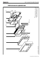
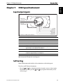
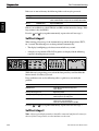
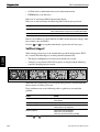
ST40 instrument construction
1
2
4
3
7
5 (x2)
9a (Note A)
6 (x2),
Torque to 2 lb in
9b (Note A)
8
D4812-1
Note:
A. It is recommended that new case seals, innner
and outer (9a and 9b) are fitted on re-assembly.
B. Rear labels are supplied in a pack for all
ST40 instruments. The Speed label is illustrated.
10 (Note B)
Part 1 Instrument Disassembly & Reassembly
ST40 Instrument exploded view
ST40 Instruments Service Manual 83149-2
Part 1 Instrument Disassembly & Assembly
ST40 instrument spare parts list
The item numbers are shown in the ST40 instrument construction illustration.
Item
Description
Part No.
Comments
1
Bezel
Grey
E25020
Standard
Silver
E25021
Optional
Carbon
E25022
Optional
Flip-flop
E25023
Optional
2
Front fascia
A28072
3
PCB/LCD/Spade assembly
Speed
Depth
Bidata
Wind
Compass
A28074
A28075
A28077
A28076
A28078
Each PCB/LCD/Spade assembly includes
4
Display label (appropriate to PCB/LCD/Spade Assembly type)
5
Washer (x2)
6
Screw (x2)
7
Keypad mat
A28079
8
Back case
A28073
Includes
9a
Case seal, inner
9b
Case seal, outer
10
Rear labels (x5, one for each instrument type)
–
Suncover
E25027
Not illustrated
Disassembly
In order to completely disassemble an ST40 instrument, ensure you have a Back
Case Removal Tool, Part No. E25031, available from Raymarine.
As it is recommended that new inner and outer seals (9a) and (9b) are fitted each time
an ST40 instrument is reassembled, ensure that new seals are available, before
commencing disassembly.
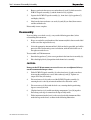
To disassemble an ST40 instrument:
1.
Referring to the Removing bezel illustration (overleaf), unclip the bezel (1)
from the front fascia (2) as follows:
(a)
ST40 Instruments Service Manual 83149-2
Hold the instrument in both hands with the display towards you.
1-1
Part 1 Instrument Disassembly & Assembly
(b)
At the control-key end of the instrument, gently press one corner of the
screen, at the same time easing-out the edges of the bezel with your
fingers, then repeat the procedure at the adjacent corner, to release that
end of the instrument from the bezel.
40
ST
Do NOT attempt to release this
end of the the bezel until you have
first released the other end.
Always release this
end of the bezel first.
Removing bezel
(c)
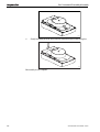
2.
At the other end of the instrument, ease the top and bottom bezel edges
outwards to unclip them, then withdraw the instrument, from the bezel.
Insert the back case removal tool between the front fascia (2) and the back
case (8) as shown, then gently twist the tool to prise the front fascia from the
back cover.
Separating front fascia from back cover
3.
1-2
D4841-4
D5039-1
Repeat this procedure for each edge of the instrument, until the front fascia
and the back case are completely separated.
ST40 Instruments Service Manual 83149-2
Part 1 Instrument Disassembly & Assembly
4.
Remove and retain the two screws and washers (6) and (5) which secure the
PCB/LCD spade assembly (3) and the front fascia (2) together.
5.
Separate the PCB/LCD spade assembly (3), front fascia (2), keypad mat (7)
and display label (4).
6.
Note how the inner and outer case seals (9a) and (9b) are fitted, then remove
and discard both seals.
Disassembly is now complete.
Reassembly
If you are fitting a new back case (8), carry out the following procedure, before
reassembling the instrument:
1.
Keep a record of the serial number of the instrument (this is shown on the label
on the rear of the original back case).
2.
Select the appropriate instrument label (10) from the five provided, peel off the
protective sheet and ensuring correct orientation, stick the label to the rear of
the replacement back case.
To reassemble an ST40 instrument:
1.
Insert the keypad mat (7) in its correct position in the front fascia assembly (2).
2.
Place the display label (4) in position in the front fascia assembly.
CAUTION:
Damage to the ST40 instrument can occur if screws are overtightened. Always
use the recommended torque values.
3.
Fit the PCB/LCD/spade assembly (3) to the front fascia (2) and secure these
items together with the two screws and washers (6) and (5). Tighten to a
torque of 22 Nm (2 lb inches).
4
Fit a new inner seal (9a) to the rear of the PCB/LCD/spade assembly (3),
ensuring that it is correctly orientated and that it lies flat on the carrier.
5
Fit a new outer seal (9b) inside the back case, ensuring that the positioning
lugs are correctly located.
6.
Clip the front fascia (2) and the remaining components (3) to (10) together.
Press along each edge to ensure that all clips are fully made.
7.
Fit the instrument into the bezel, so the curved end of the instrument slides
under the lugs on the bezel, as shown in the following illustration.
ST40 Instruments Service Manual 83149-2
1-3
Part 1 Instrument Disassembly & Assembly
D5038-1
8
Gently but firmly press the bezel onto the instrument until it clicks into place.
D5038-2
Reassembly is now complete.
1-4
ST40 Instruments Service Manual 83149-2
Part 2 Instrument Servicing
Part 2 Instrument Servicing
Contents
Chapter 1: ST40 Speed Instrument ....................................................................... 2-1
Input/output signals .................................................................................... 2-1
Self-testing ................................................................................................ 2-1
Self test stage 1 ...................................................................................... 2-2
Self-test stage 2 ..................................................................................... 2-2
Self-test stage 3 ..................................................................................... 2-3
ST40 Speed PCB assembly ......................................................................... 2-4
ST40 Speed PCB assembly component list ............................................. 2-6
Chapter 2: ST40 Depth Instrument ....................................................................... 2-9
Input/output signals .................................................................................... 2-9
Self-test procedure ..................................................................................... 2-9
Self test stage 1 ...................................................................................... 2-9
Self-test stage 2 ................................................................................... 2-10
Self-test stage 3 ................................................................................... 2-10
ST40 Depth PCB assembly ....................................................................... 2-12
ST40 Depth PCB assembly component list ........................................... 2-14
Chapter 3: ST40 Bidata Instrument ..................................................................... 2-19
Input/output signals .................................................................................. 2-19
Self-test procedure ................................................................................... 2-19
Self test stage 1 .................................................................................... 2-20
Self-test stage 2 ................................................................................... 2-20
Self-test stage 3 ................................................................................... 2-21
ST40 Bidata PCB assembly ...................................................................... 2-22
ST40 Bidata PCB assembly component list .......................................... 2-24
Chapter 4: ST40 Wind Instrument ....................................................................... 2-29
Input/output signals .................................................................................. 2-29
Self-test procedure ................................................................................... 2-29
Self test stage 1 .................................................................................... 2-29
Self-test stage 2 ................................................................................... 2-30
Self-test stage 3 ................................................................................... 2-31
ST40 Wind PCB assembly ........................................................................ 2-32
ST40 Wind PCB assembly component list ............................................ 2-34
ST40 Instruments Service Manual 83149-2
Part 2 Instrument Servicing
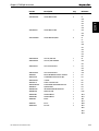
Chapter 5: ST40 Compass Instrument ................................................................. 2-37
Input/output signals .................................................................................. 2-37
Self-test procedure ................................................................................... 2-37
Self test stage 1 .................................................................................... 2-37
Self-test stage 2 ................................................................................... 2-38
Self-test stage 3 ................................................................................... 2-39
ST40 Compass PCB assembly .................................................................. 2-40
ST40 Compass PCB assembly component list ...................................... 2-42
ST40 Instruments Service Manual 83149-2
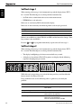
Chapter 1, ST40 Speed Instrument
ST40 Speed Instrument
E22037
Chapter 1:
Input/output signals
Raymarine
Limited
STALK (Yellow)
BATT- (Screen)
BATT+ (Red)
12V (Red)
SPD (Green)
SCREEN (Screen)
TEMP (White)
0VANA (Brown)
Connections to ST40 Speed instrument
Signal
Description
STALK
Intermittent streams of (nominal) 12 V pulses
BATT-
0V
BATT+
Nominal 12 V dc supply
12V
Approximately 11.2 V dc out
SPD
With transducer attached, spinning paddle-wheel produces pulses
approximately 11.2 V in amplitude @ 5.5 Hz/Knot.
SCREEN
0V
TEMP
With transducer attached, voltage here is dependent on
temperature. Approximately 1.8 V at 0 degrees C.
OVANA
0V
D4804-2
Refer also to the ST40 Speed circuit diagram.
Self-testing
Each ST40 instrument has built-in self-test functions to aid fault diagnosis.
To self-test an ST40 Speed instrument:
• Press the and keys simultaneously for 4 seconds, to access self-test mode,
then within 2 seconds, press the and keys together momentarily, to start
self-test stage 1.
ST40 Instruments Service Manual 83149-2
2-1
Part 2 Instrument Servicing
E22037
Self test stage 1
When entering self test stage 1, the instrument beeps and the display shows TEST 1,
for 1 second. The following tests are then performed automatically:
• SeaTalk self test, which checks the receive and transmit circuits.
• EEPROM test (read and write).
If the tests are satisfactory, PASS is shown on the display.
If the tests are not satisfactory, the following failure codes may be generated:
Message
Failure
Action
FAIL 8
SeaTalk Rx/Tx
Check SeaTalk interface components around TR5
FAIL 18
EEPROM
Replace EEPROM (IC3)
If there is no audible beep, check TR19(b) and RN3 and the buzzer for damage. If the
beep volume is low, check R93.
Press the
and
keys together momentarily, to proceed to self-test stage 2.
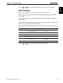
Self-test stage 2
When entering self test stage 2, the instrument beeps and the display shows TEST 2,
for 1 second. The following tests are then performed automatically:
• The display backlighting cycles between on and off every second.
• A display test is performed. The LCD segments are displayed in the following
sequence, changing once per second:
CAL
D4887-1
While this test is progressing, press each of the front panel keys and check that the
buzzer sounds as each key is pressed.
If any problems occur, use the following table as a guide to try to remedy the
problem:
2-2
Failure
Action
No illumination
Check TR18 and associated components.
Check all LEDs.
No beep when key pressed
Replace keyswitch.
LCD segment(s) missing completely
Check LCD pins for poor/dry joints.
Check IC7 pins for poor/dry joints.
Faint LCD segments
Check LCD for short circuited pins.
Check IC7 for short circuited pins.
Check the contrast drive circuit around TR6.
ST40 Instruments Service Manual 83149-2
Chapter 1, ST40 Speed Instrument
and
keys together momentarily, to proceed to self-test stage 3.
E22037
Press the
Self-test stage 3
Note: A known good speed transducer must be connected for this test.
When entering self test stage 3, the instrument beeps and the display shows TEST3,
for 1 second.
A transducer test then starts. Manually spin the paddle wheel within 15 seconds of
starting this test.
If the instrument detects valid temperature and speed pulses within 15 seconds of the
start of test stage 3, PASS is shown on the display.
If the test fails, FAIL44 is displayed. Use the following table to try to isolate the cause.
Check
Failure mode
Action
Voltage at P11
Voltage approx. 11 V with
12 V battery supply
Check TR10, R59 and associated
components.
L10
Open circuit
Replace L10.
L11
Open circuit
Replace L11.
D4c
Open circuit
Replace D4.
Voltage at TEMP pin
Outside range of 0.76 V to 1.00 V
(at 18°C to 25°C)
Check L14 for open circuit.
Check R60.
AVREF
Outside range of 2.5 V ±0.25 V
Check TR20, R61 & R62
Press the
ST40 Instruments Service Manual 83149-2
and
keys together momentarily to exit self-test.
2-3
Part 2 Instrument Servicing
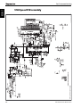
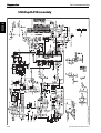
ST40 Speed PCB circuit diagram
D4878-1 (from Drawing No. 4465-004, issue D)
E22037
ST40 Speed PCB assembly
2-4
ST40 Instruments Service Manual 83149-2
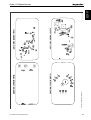
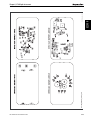
ST40 Speed PCB layout diagram
ST40 Instruments Service Manual 83149-2
2-5
E22037
D4889_1 (from Drawing No. 4465-001, issue B)
Chapter 1, ST40 Speed Instrument
Part 2 Instrument Servicing
E22037
ST40 Speed PCB assembly component list
Part No.
Description
Qty
Reference
03065
CAP 100uF 16V
1
C2
06030
ALPS TACT. SWITCH (RED)
3
SW1
SW2
SW3
15136
BUZZER EFM-250D
1
BZ1
15165
LED LTIF24-A2 GREEN
4
LED1
LED2
LED3
LED4
4465-001SM
ST40 SPEED SM PCB ASSY
1
3015-201-D
ST40 DIGITAL PCB
1
91010R0
ZERO OHM LINK, 0603 PACKAGE
2
R114
R121
910210R
910212K
RESISTOR 10 OHM 0805
RESISTOR 12K+-5% 0805 0.1W
1
1
R8
R5
910215K
RESISTOR 15K+-5% 0805 0.1W
2
R9
R58
91021K5
RESISTOR 1K5+-5% 0805 0.1W
5
R39
R34
R35
R36
R65
910239K
RESISTOR 39K+-5% 0805 0.1W
3
R1
R10
91033K
RESISTOR 3K0 1% 1206 1/8W
1
R12
R68
9103430K
RESISTOR 430K, 1206
1
R20
9106180K
RESISTOR 180K, 1206
1
R41
910618R
RESISTOR 18 OHM +/-5% - 1206
1
R91
910622R
RESISTOR 22 OHM 1206
1
R59
91062K7
9106390R
RESISTOR 2K7 OHM, 1206
RESISTOR 390R, 1206
1
1
R61
R2
910656K
RESISTOR 56K, 1206
1
R60
9106680R
RESISTOR 680R, 1206
3
R22
R38
R93
9108VC260540
91124K7
TRANSGUARD
RESISTOR NETWORK
1
4
V1
RN1
RN2
RN3
RN4
91AAAXXX10K
RESISTOR 10K,1% 0.063W 0603
3
R4
R13
R120
2-6
ST40 Instruments Service Manual 83149-2
Part No.
Description
Qty
Reference
91AAAXXX1K0
RESISTOR 1.0K,1% 0.063W 0603
4
R7
E22037
Chapter 1, ST40 Speed Instrument
R40
R64
R67
91AAAXXX2K2
RESISTOR 2.2K,1% 0.063W 0603
2
R3
91AAAXXX47K
RESISTOR 47K,1% 0.063W 0603
1
R119
91AAAXXX4K7
RESISTOR 4.7K,1% 0.063W 0603
6
R11
R37
R6
R42
R62
R69
R66
9200BAS19
DIODE SOT23 BAS19
3
D1
D2
D8
9203BZX84C5V1
5V1 ZENER
1
D7
9206IMN10
TRIPLE DIODE ARRAY - ISOLATED
1
D4
930133P
CAPACITOR 33pF, 0805
2
C30
93091U
CAPACITOR 1uF, TANT
1
C31
C9
9326100U
CAPACITOR 100uF 10V+-20% TANT
1
C4
93261U
CAPACITOR Y5V 1206 1uF 50V
1
C1
93ADEBXX47N
CAPACITOR 47nF, 0603
1
C66
93ADHBXX10N
CAPACITOR 10nF XR7
5
C5
C10
C29
C33
C36
93ADHBXX1N
93AFFDXX100N
CAPACITOR 1nF 0603
CAPACITOR 100nF, 0603
2
C34
4
C64
C3
C13
C32
C35
93BDHXXX2N2
CAP. 2n2, 0805 X7R
1
C6
93IDDCXX22U
CAP. 22uF TANT. ELECT
2
C58
C65
93HDECXX22U
CAP. 22uF TANT. ELECT
1
C76
940024022
RESET CONTROLLER S24O22 +2KME
1
IC3
94007225GB
LCD DRIVER UPD7225GB-3B7 QFP
1
IC7
940074HC74
DUAL D-TYPE FLIP FLOP
1
IC2
940078F0034GK
9400LM78L05
FLASH MICRO UPD78FOO34AGK-8A8
VOLT REGULATOR LM78L05ACM
1
1
IC6
IC1
95002B1132
TRANSISTOR 2W PNP 2SB1132T100
1
TR10
ST40 Instruments Service Manual 83149-2
2-7
E22037
Part 2 Instrument Servicing
Part No.
Description
Qty
Reference
95002N7002
2N7002 MOSFET
2
TR14
TR21
9500BC807
BC807
1
TR11
9500BC817
BC817
1
TR20
9500BC849C
9500IMT1
BC 849C
DUAL TRANSISTOR ARRAY
1
1
TR12
TR5
9500IMX1
DIGITAL TRANSISTOR ARRAY
5
TR2
TR3
TR6
TR15
9500IMZ1
DUAL TRANSISTOR ARRAY
1
TR19
TR1
9501BC868
BC868
1
TR18
96004MHZ
CRYSTAL 4.0MHz, HC49/4HSMX
1
XT1
9600L1
CHIP INDUCTOR
4
L3
L8
L13
L15
9600L13
INDUCTOR, 3.3uH +/-20%
1
9600L3
CHIP INDUCTOR, 10uH +/-20%
6
L12
L1
L2
L10
L11
L14
L20
2-8
ST40 Instruments Service Manual 83149-2
Chapter 2, ST40 Depth Instrument
Chapter 2:
ST40 Depth Instrument
EE2203822038
E22038
Input/output signals
DEPTH- (Black)
DEPTH+ (Blue)
DEPTH_0V (Screen)
Raymarine
Limited
STALK (Yellow)
BATT- (Screen)
BATT+ (Red)
Connections to instrument
Signal
Description
STALK
Intermittent streams of (nominal) 12 V pulses
BATT-
0V
BATT+
Nominal 12 V dc supply
DEPTH-
Intermittent pulses at 200 kHz, approximately 400 µs wide, 300 V peak-to-peak
DEPTH+
Intermittent pulses at 200 kHz, approximately 400 µs wide, 300 V peak-to-peak
DEPTH_0V
0V
D4805-2
Refer also to the ST40 Depth circuit diagram.
Self-test procedure
Each ST40 instrument has built-in self-test functions to aid fault diagnosis.
To self-test an ST40 Depth instrument:
• Press the and keys simultaneously for 4 seconds, to access self-test mode,
then within 2 seconds, press the and keys together momentarily, to start
self-test stage 1.
Self test stage 1
When entering self test stage 1, the instrument beeps and the display shows TEST 1,
for 1 second. The following tests are then performed automatically:
• SeaTalk self test, which checks the receive and transmit circuits.
• EEPROM test (read and write).
If the tests are satisfactory, PASS is shown on the display.
ST40 Instruments Service Manual 83149-2
2-9
Part 2 Instrument Servicing
E22038
If the tests are not satisfactory, the following failure codes may be generated:
Message
Failure Mode
Action
FAIL 8
SeaTalk Rx/Tx
Check for damaged bucket connectors/rear-case pins.
Check SeaTalk interface components around TR1, TR2 and TR3.
FAIL 18
EEPROM failure
Replace EEPROM (IC2)
If there is no audible beep, check TR19(b) and RN3 and the buzzer for damage. If the
beep volume is low, check R93.
Press the
and
keys together momentarily, to proceed to self-test stage 2.
Self-test stage 2
When entering self test stage 2, the instrument beeps and the display shows TEST 2,
for 1 second. The following tests are then performed automatically:
• The display backlighting cycles between on and off every second.
• A display test is performed. The LCD segments are displayed in the following
sequence, changing once per second:
CAL
D4887-1
While this test is progressing, press each of the front panel keys and check that the
buzzer sounds as each key is pressed.
If any problems occur, use the following table as a guide to try to remedy the
problem:
Failure
Action
No illumination
Check TR18 and associated components.
Check all LEDs.
No beep when key pressed
Replace keyswitch.
LCD segment(s) missing completely
Check LCD pins for poor/dry joints.
Check IC7 pins for poor/dry joints.
Faint LCD segments
Check LCD for short circuited pins.
Check IC7 for short circuited pins.
Check the contrast drive circuit around TR6.
Press the
and
keys together momentarily, to proceed to self-test stage 3.
Self-test stage 3
Note: A known good depth transducer should be connected and placed in water, for
this test. If this is not possible, an echo simulator can be used.
2-10
ST40 Instruments Service Manual 83149-2
Chapter 2, ST40 Depth Instrument
When entering self test stage 3, the instrument beeps and the display shows TEST3,
for 1 second.
A transducer test then starts. If the interface is working correctly, PASS is displayed.
Check
Failure mode
Action
Pulses at IC5, pins 1 & 4
No pulses
Check R113
Check IC5 and replace if suspect
Check for dry joints at IC6 pins 46 & 49.
Pulses at TR4 drain
No pulses
Check R123
Pulses at TR8 drain
No pulses
Check R124
Pulses at DEPTH+ & DEPTH-
No pulses
Check TR4, TR8 & T1
Depth receiver output pulses
at IC4, pin 14
No pulses
Return instrument to Raymarine Ltd.
Press the
ST40 Instruments Service Manual 83149-2
and
E22038
If the test fails, FAIL 43 is displayed. Use the following table to try to isolate the cause.
keys together momentarily to exit self-test.
2-11
Part 2 Instrument Servicing
ST40 Depth PCB circuit diagram
E22038
D4879-1 (from Drawing No. 4465-005, issue D)
ST40 Depth PCB assembly
2-12
ST40 Instruments Service Manual 83149-2
ST40 Depth PCB layout diagram
ST40 Instruments Service Manual 83149-2
2-13
E22038
D4890_1 (from Drawing No. 4465-002, issue B)
Chapter 2, ST40 Depth Instrument
Part 2 Instrument Servicing
E22038
ST40 Depth PCB assembly component list
Part No.
Description
Qty
Reference
03065
03066
CAP 100uF 16V
CAP 1000uF 16V ELECT.
1
1
C2
C8
03083
CAPACITOR 2200pF - 1kV
1
C23
06030
ALPS TACT. SWITCH (RED)
3
SW1
SW2
SW3
15134
15136
XFORMER
BUZZER EFM-250D
1
1
T1
BZ1
15165
LED LTIF24-A2 GREEN
4
LED1
LED2
LED3
LED4
15172
F.E.T. STK 12N05L
2
TR4
TR8
4465-002SM
ST40 DEPTH SM PCB ASSY
1
3015-201-D
ST40 DIGITAL PCB
1
91010R0
ZERO OHM LINK, 0603 PACKAGE
2
R55
9102100K
RESISTOR 100K+-5% 0805 0.1W
2
R115
R47
R96
910210R
RESISTOR 10 OHM 0805
2
910212K
RESISTOR 12K+-5% 0805 0.1W
3
R8
R19
R5
R43
R94
910215K
RESISTOR 15K+-5% 0805 0.1W
2
R9
91021K5
RESISTOR 1K5+-5% 0805 0.1W
5
R34
R54
R35
R36
R39
R65
910222K
RESISTOR 22K+-5% 0805 .1W
2
R48
R100
910239K
RESISTOR 39K+-5% 0805 0.1W
4
R1
R10
R12
R107
2-14
910268K
RESISTOR 68K+-5% 0805 0.1W
1
R95
9103100R
RESISTOR 100R, 1206
1
R17
910310K
RESISTOR, 10K 1% 1206
1
R18
91033K
RESISTOR 3K0 1% 1206 1/8W
2
R68
R106
ST40 Instruments Service Manual 83149-2
Chapter 2, ST40 Depth Instrument
Description
Qty
Reference
9103430K
91036K8
RESISTOR 430K, 1206
RESISTOR 6K8, 1206
1
1
R20
R125
91060R0
RESISTOR 0R0, 1206
1
R126
910616K
RESISTOR 16K, 1206 0.1W
2
R49
E22038
Part No.
R105
9106180K
RESISTOR 180K, 1206
1
R41
910618R
91061K2
RESISTOR 18 OHM +/-5% - 1206
RESISTOR 1K2, 1206
1
1
R91
R52
91062K7
RESISTOR 2K7 OHM, 1206
1
R61
9106390R
RESISTOR 390R, 1206
3
R2
R123
R124
910656K
9106680R
RESISTOR 56K, 1206
RESISTOR 680R, 1206
1
3
R102
R22
R38
R93
9108VC260540
TRANSGUARD
1
V1
91124K7
RESISTOR NETWORK
4
RN1
RN2
RN3
RN4
91AAAXX100R
RESISTOR 100R,1% 0.063W 0603
1
91AAAXXX10K
RESISTOR 10K,1% 0.063W 0603
5
R46
R4
R13
R111
R112
R120
91AAAXXX1K0
RESISTOR 1.0K,1% 0.063W 0603
5
R7
R40
R64
R67
R108
91AAAXXX2K2
RESISTOR 2.2K,1% 0.063W 0603
3
R3
R6
R98
91AAAXXX3K3
RESISTOR 3.3K,1% 0.063W 0603
3
R50
R99
R113
91AAAXXX47K
RESISTOR 47K,1% 0.063W 0603
8
R32
91AAAXXX47K
RESISTOR 47K,1% 0.063W 0603
8
R45
R44
R53
R97
R101
R103
R119
ST40 Instruments Service Manual 83149-2
2-15
Part 2 Instrument Servicing
Part No.
Description
Qty
Reference
91AAAXXX4K7
RESISTOR 4.7K,1% 0.063W 0603
11
R11
R28
R29
E22038
R37
R42
R62
R66
R69
R104
R109
R110
9200BAS19
DIODE SOT23 BAS19
4
D1
D2
D3
D8
9200BAV99
BAV99 DIODE
2
D5
D6
9206IMN10
TRIPLE DIODE ARRAY - ISOLATED
1
D4
930122P
930133P
CAPACITOR 22P, 0805
CAPACITOR 33pF, 0805
1
2
C24
C30
C31
9301470P
CAPACITOR 470pf 100v +-5% 0805
1
C18
93060U047
CAPACITOR 0.047uF,
2
C16
2
C56
C9
93091U
CAPACITOR 1uF, TANT
C22
93102U2
CAPACITOR 2.2uF
1
C26
9326100U
CAPACITOR 100uF 10V+-20% TANTA
1
C4
93261U
CAPACITOR Y5V 1206 1uF 50V
12
C1
C15
C62
C63
C67
C68
93261U
CAPACITOR Y5V 1206 1uF 50V
12
C69
C70
C71
C72
C73
C74
93ADEBXX47N
2-16
CAPACITOR 47nF, 0603
1
C66
ST40 Instruments Service Manual 83149-2
Chapter 2, ST40 Depth Instrument
Part No.
Description
Qty
Reference
93ADHBXX10N
CAPACITOR 10nF XR7
6
C5
C10
C14
E22038
C25
C33
C36
93ADHBXX1N
CAPACITOR 1nF 0603
3
C34
C54
C64
93AFFDXX100N
CAPACITOR 100nF, 0603
9
C3
C7
C13
C20
C21
C28
C35
C55
C61
93BDHXXX2N2
93BDHXXX4N7
CAP. 2n2, 0805 X7R
CAP. 4n7, 0805 CERAMIC
1
1
C6
C19
C27
93IDDCXX22U
CAP. 22uF TANT. ELECT
3
C17
C58
C65
93HDECXX22U
940024022
CAP. 22uF TANT. ELECT
RESET CONTROLLER S24O22 +2KMEM
1
1
C76
IC3
94007225GB
LCD DRIVER UPD7225GB-3B7 QFP
1
IC7
940074AHC02
IC LOGIC
1
IC5
940074HC74
DUAL D-TYPE FLIP FLOP
1
IC2
940078F0034GK
FLASH MICRO UPD78FOO34AGK-8A8
1
IC6
9400LM339
9400LM78L05
QUAD OP AMP
VOLT REGULATOR LM78L05ACM
1
1
IC4
IC1
9400TIOP07C
OP07C OP-AMP
1
IC10
95002N7002
2N7002 MOSFET
2
TR14
95002N7002
2N7002 MOSFET
2
TR21
9500BC807
BC807
2
TR9
9500BC817
BC817
1
TR13
TR20
9500BC849C
BC 849C
4
TR12
TR22
TR23
TR24
ST40 Instruments Service Manual 83149-2
2-17
Part 2 Instrument Servicing
Part No.
Description
Qty
Reference
9500BCW61D
BCW61D
1
TR25
9500IMT1
DUAL TRANSISTOR ARRAY
1
TR5
9500IMX1
DIGITAL TRANSISTOR ARRAY
5
TR2
E22038
TR3
TR6
TR15
TR19
9500IMZ1
DUAL TRANSISTOR ARRAY
1
TR1
9501BC868
BC868
1
TR18
96004MHZ
9600FILTER1
CRYSTAL 4.0MHz, HC49/4HSMX
CERAMIC FILTER
1
1
XT1
RES1
9600L1
CHIP INDUCTOR
6
L3
L8
L9
L13
L15
L21
9600L13
INDUCTOR, 3.3uH +/-20%
1
L12
9600L3
CHIP INDUCTOR, 10uH +/-20%
3
L1
L2
L22
2-18
ST40 Instruments Service Manual 83149-2
Chapter 3, ST40 Bidata Instrument
Chapter 3:
ST40 Bidata Instrument
Input/output signals
DEPTH- (Black)
DEPTH+ (Blue)
DEPTH_0V (Screen)
E22039
Raymarine
Limited
STALK (Yellow)
BATT- (Screen)
BATT+ (Red)
12V_SPD (Red)
SPD (Green)
SCREEN (Screen)
TEMP (White)
0VANA (Brown)
Connections to instrument
Signal
Description
STALK
Intermittent streams of (nominal) 12 V pulses
BATT-
0V
BATT+
Nominal 12 V dc supply
DEPTH-
Intermittent pulses at 200 kHz, approximately 400 µs wide, 300 V peak-to-peak
DEPTH+
Intermittent pulses at 200 kHz, approximately 400 µs wide, 300 V peak-to-peak
DEPTH_0V
12V
0V
Approximately 11.2 V dc out
SPD
With transducer attached, spinning paddle-wheel produces pulses
approximately 11.2 V in amplitude @ 5.5 Hz/Knot.
SCREEN
0V
TEMP
With transducer attached, voltage here is dependent on
temperature. Approximately 1.8 V at 0 degrees C.
OVANA
0V
D4810-2
Refer also to the ST40 Bidata circuit diagram.
Self-test procedure
Each ST40 instrument has built-in self-test functions to aid fault diagnosis.
To self-test an ST40 Bidata instrument:
• Press the and keys simultaneously for 4 seconds, to access self-test mode,
then within 2 seconds, press the and keys together momentarily, to start
self-test stage 1.
ST40 Instruments Service Manual 83149-2
2-19
Part 2 Instrument Servicing
Self test stage 1
When entering self test stage 1, the instrument beeps and the display shows TEST 1,
for 1 second. The following tests are then performed automatically:
• SeaTalk self test, which checks the receive and transmit circuits.
• EEPROM test (read and write).
If the tests are satisfactory, PASS is shown on the display.
E22039
If the tests are not satisfactory, the following failure codes may be generated:
Message
Failure Mode
Action
FAIL 8
SeaTalk Rx/Tx
Check for damaged bucket connectors/rear-case pins.
Check SeaTalk interface components around TR1, TR2 and TR3.
FAIL 18
EEPROM failure
Replace EEPROM (IC2)
If there is no audible beep, check TR19(b) and RN3 and the buzzer for damage. If the
beep volume is low, check R93.
Press the
and
keys together momentarily, to proceed to self-test stage 2.
Self-test stage 2
When entering self test stage 2, the instrument beeps and the display shows TEST 2,
for 1 second. The following tests are then performed automatically:
• The display backlighting cycles between on and off every second.
• A display test is performed. The LCD segments are displayed in the following
sequence, changing once per second:
CAL
D4887-1
While this test is progressing, press each of the front panel keys and check that the
buzzer sounds as each key is pressed.
If any problems occur, use the following table as a guide to try to remedy the
problem:
2-20
Failure
Action
No illumination
Check TR18 and associated components.
Check all LEDs.
No beep when key pressed
Replace keyswitch.
LCD segment(s) missing completely
Check LCD pins for poor/dry joints.
Check IC7 pins for poor/dry joints.
Faint LCD segments
Check LCD for short circuited pins.
Check IC7 for short circuited pins.
Check the contrast drive circuit around TR6.
ST40 Instruments Service Manual 83149-2
Chapter 3, ST40 Bidata Instrument
Press the
and
keys together momentarily, to proceed to self-test stage 3.
Self-test stage 3
Note: Known good Speed and Depth transducers must be connected, for this test,
with the Depth transducer placed in water. If this is not possible, an echo simulator
can be used in place of the Depth transducer.
A transducer test then starts. At the Speed transducer, manually spin the paddle
wheel within 15 seconds of starting this test.
If the instrument detects valid temperature and speed pulses within 15 seconds of the
start of test stage 4 and if the Depth transducer interface is satisfactory, PASS is shown
on the display.
If the test fails, either a FAIL44 (speed circuit) or FAIL43 (depth circuit) is indicated.
Use the appropriate table in either Chapter 1, ST40 Speed Instrument or Chapter 2,
ST40 Depth Instrument, to isolate the cause.
Press the
ST40 Instruments Service Manual 83149-2
and
keys together momentarily to exit self-test.
2-21
E22039
When entering self test stage 3, the instrument beeps and the display shows TEST3,
for 1 second.
Part 2 Instrument Servicing
ST40 Bidata PCB circuit diagram
E22039
D4880_1 (from Drawing No. 4465-006, issue D)
ST40 Bidata PCB assembly
2-22
ST40 Instruments Service Manual 83149-2
ST40 Bidata PCB layout diagram
E22039
D4891_1 (from Drawing No. 4465-003, issue B)
Chapter 3, ST40 Bidata Instrument
ST40 Instruments Service Manual 83149-2
2-23
Part 2 Instrument Servicing
ST40 Bidata PCB assembly component list
Part No.
Description
Qty
Reference
03065
CAP 100uF 16V
1
C2
03066
03083
CAP 1000uF 16V ELECT.
CAPACITOR 2200pF - 1kV
1
1
C8
C23
06030
ALPS TACT. SWITCH (RED)
3
SW1
SW2
E22039
SW3
15134
XFORMER
1
T1
15136
15165
BUZZER EFM-250D
LED LTIF24-A2 GREEN
1
4
BZ1
LED1
LED2
LED3
LED4
15172
F.E.T. STK 12N05L
2
TR4
TR8
4465-003SM
ST40 BIDATA SM PCB ASSY
1
3015-201-D
ST40 DIGITAL PCB
1
91010R0
ZERO OHM LINK, 0603 PACKAGE
3
R55
R116
9102100K
RESISTOR 100K+-5% 0805 0.1W
2
R121
R47
R96
910210R
RESISTOR 10 OHM 0805
2
R8
R19
910212K
RESISTOR 12K+-5% 0805 0.1W
3
R5
R43
R94
910215K
RESISTOR 15K+-5% 0805 0.1W
3
R9
R54
R58
91021K5
RESISTOR 1K5+-5% 0805 0.1W
5
R39
R34
R35
R36
R65
910222K
RESISTOR 22K+-5% 0805 .1W
2
R48
R100
910239K
RESISTOR 39K+-5% 0805 0.1W
4
R1
R10
R12
R107
2-24
910268K
RESISTOR 68K+-5% 0805 0.1W
1
R95
9103100R
RESISTOR 100R, 1206
1
R17
910310K
RESISTOR, 10K 1% 1206
1
R18
ST40 Instruments Service Manual 83149-2
Chapter 3, ST40 Bidata Instrument
Description
Qty
Reference
91033K
RESISTOR 3K0 1% 1206 1/8W
2
R68
R106
9103430K
RESISTOR 430K, 1206
1
R20
91036K8
RESISTOR 6K8, 1206
1
R125
91060R0
RESISTOR 0R0, 1206
1
R126
910616K
RESISTOR 16K, 1206 0.1W
2
R49
9106180K
RESISTOR 180K, 1206
1
R105
R41
910618R
RESISTOR 18 OHM +/-5% - 1206
1
R91
91061K2
RESISTOR 1K2, 1206
1
R52
910622R
RESISTOR 22 OHM 1206
1
R59
91062K7
RESISTOR 2K7 OHM, 1206
1
R61
9106390R
RESISTOR 390R, 1206
3
R2
R123
E22039
Part No.
R124
910656K
RESISTOR 56K, 1206
2
R60
R102
9106680R
RESISTOR 680R, 1206
3
R22
R38
R93
9108VC260540
TRANSGUARD
1
V1
91124K7
RESISTOR NETWORK
4
RN1
RN2
RN3
91AAAXX100R
RESISTOR 100R,1% 0.063W 0603
1
RN4
R46
91AAAXXX10K
RESISTOR 10K,1% 0.063W 0603
5
R4
R13
R111
R112
91AAAXXX1K0
RESISTOR 1.0K,1% 0.063W 0603
5
R120
R7
R40
R64
R67
R108
91AAAXXX2K2
RESISTOR 2.2K,1% 0.063W 0603
3
R3
R6
R98
91AAAXXX3K3
RESISTOR 3.3K,1% 0.063W 0603
3
R50
R99
R113
ST40 Instruments Service Manual 83149-2
2-25
Part 2 Instrument Servicing
Part No.
91AAAXXX47K
Description
RESISTOR 47K,1% 0.063W 0603
Qty
Reference
8
R32
R44
R45
R53
R97
R101
R103
E22039
R119
91AAAXXX4K7
RESISTOR 4.7K,1% 0.063W 0603
11
R11
R28
R29
R37
R42
R62
R66
R69
R104
R109
R110
9200BAS19
DIODE SOT23 BAS19
4
D1
D2
D3
D8
9200BAV99
BAV99 DIODE
2
D5
D6
9203BZX84C5V1
5V1 ZENER
1
D7
9206IMN10
930122P
TRIPLE DIODE ARRAY - ISOLATED
CAPACITOR 22P, 0805
1
1
D4
C24
930133P
CAPACITOR 33pF, 0805
2
C30
C31
9301470P
CAPACITOR 470pf 100v +-5% 0805
1
C18
93060U047
CAPACITOR 0.047uF,
2
C16
C56
C9
93091U
CAPACITOR 1uF, TANT
2
93102U2
CAPACITOR 2.2uF
1
C26
9326100U
CAPACITOR 100uF 10V+-20% TANTA
1
C4
93261U
CAPACITOR Y5V 1206 1uF 50V
7
C1
93261U
CAPACITOR Y5V 1206 1uF 50V
7
C15
C62
C22
C63
C67
C68
C69
93ADEBXX47N
2-26
CAPACITOR 47nF, 0603
1
C66
ST40 Instruments Service Manual 83149-2
Chapter 3, ST40 Bidata Instrument
Part No.
93ADHBXX10N
Description
CAPACITOR 10nF XR7
Qty
Reference
7
C5
C10
C14
C25
C29
C33
CAPACITOR 1nF 0603
3
E22039
93ADHBXX1N
C36
C34
C54
C64
93AFFDXX100N
CAPACITOR 100nF, 0603
11
C3
C7
C13
C20
C21
C28
C32
C35
C55
C57
C61
93BDHXXX2N2
CAP. 2n2, 0805 X7R
1
93BDHXXX4N7
CAP. 4n7, 0805 CERAMIC
2
C6
C19
C27
93IDDCXX22U
CAP. 22uF TANT. ELECT
3
C17
C58
93HDECXX22U
CAP. 22uF TANT. ELECT
1
C76
940024022
RESET CONTROLLER S24O22 +2KMEM
1
IC3
94007225GB
LCD DRIVER UPD7225GB-3B7 QFP
1
IC7
940074AHC02
940074HC74
IC LOGIC
DUAL D-TYPE FLIP FLOP
1
1
IC5
IC2
940078F0034GK
FLASH MICRO UPD78FOO34AGK-8A8
1
IC6
9400LM339
QUAD OP AMP
1
IC4
9400LM78L05
VOLT REGULATOR LM78L05ACM
1
IC1
9400TIOP07C
OP07C OP-AMP
1
IC10
95002B1132
95002N7002
TRANSISTOR 2W PNP 2SB1132T100Q
2N7002 MOSFET
1
2
TR10
TR14
C65
TR21
9500BC807
BC807
3
TR9
TR11
TR13
9500BC817
ST40 Instruments Service Manual 83149-2
BC817
1
TR20
2-27
Part 2 Instrument Servicing
Part No.
9500BC849C
Description
BC 849C
Qty
Reference
4
TR12
TR22
TR23
TR24
E22039
9500BCW61D
BCW61D
1
TR25
9500IMT1
DUAL TRANSISTOR ARRAY
1
TR5
9500IMX1
DIGITAL TRANSISTOR ARRAY
5
TR2
TR3
TR6
TR15
TR19
9500IMZ1
DUAL TRANSISTOR ARRAY
1
TR1
9501BC868
96004MHZ
BC868
CRYSTAL 4.0MHz, HC49/4HSMX
1
1
TR18
XT1
9600FILTER1
CERAMIC FILTER
1
RES1
9600L1
CHIP INDUCTOR
6
L3
L8
L9
L13
L15
L21
9600L13
INDUCTOR, 3.3uH +/-20%
1
9600L3
CHIP INDUCTOR, 10uH +/-20%
7
L12
L1
L2
L10
L11
L14
L20
L22
2-28
ST40 Instruments Service Manual 83149-2
Chapter 4, ST40 Wind Instrument
Chapter 4:
ST40 Wind Instrument
Input/output signals
ROTA+ (Red)
ROTA- (Blue)
Raymarine
Limited
STALK (Yellow)
BATT- (Screen)
Connections to instrument
Signal
Description
STALK
Intermittent streams of (nominal) 12 V pulses
BATT-
0V
BATT+
Nominal 12 V dc supply
ROTA+
Rotavecta current constant
ROTA-
0V
D4836-2
Refer also to the ST40 Wind circuit diagram.
Self-test procedure
Each ST40 instrument has built-in self-test functions to aid fault diagnosis.
To self-test an ST40 Wind instrument:
• Press the and keys simultaneously for 4 seconds, to access self-test mode,
then within 2 seconds, press the and keys together momentarily, to start
self-test stage 1.
Self test stage 1
When entering self test stage 1, the instrument beeps and the display shows TEST 1,
for 1 second. The following tests are then performed automatically:
• SeaTalk self test, which checks the receive and transmit circuits.
• EEPROM test (read and write).
If the tests are satisfactory, PASS is shown on the display.
If the tests are not satisfactory, the following failure codes may be generated:
ST40 Instruments Service Manual 83149-2
2-29
E22041
BATT+ (Red)
Part 2 Instrument Servicing
Message
Failure Mode
Action
FAIL 8
SeaTalk Rx/Tx
Check for damaged bucket connectors/rear-case pins.
Check SeaTalk interface components around TR1, TR2 and TR3.
FAIL 18
EEPROM failure
Replace EEPROM (IC2)
If there is no audible beep, check TR19(b) and RN3 and the buzzer for damage. If the
beep volume is low, check R93.
Press the
and
keys together momentarily, to proceed to self-test stage 2.
Self-test stage 2
When entering self test stage 2, the instrument beeps and the display shows TEST 2,
for 1 second. The following tests are then performed automatically:
E22041
• The display backlighting cycles between on and off every second.
• A display test is performed. The LCD segments are displayed in the following
sequence, changing once per second:
CAL
STEER
D4888-1
While this test is progressing, press each of the front panel keys and check that the
buzzer sounds as each key is pressed.
If any problems occur, use the following table as a guide to try to remedy the
problem:
Failure
Action
No illumination
Check TR18 and associated components.
Check all LEDs.
No beep when key pressed
Replace keyswitch.
LCD segment(s) missing completely
Check LCD pins for poor/dry joints.
Check IC7 pins for poor/dry joints.
Faint LCD segments
Check LCD for short circuited pins.
Check IC7 for short circuited pins.
Check the contrast drive circuit around TR6.
Press the
2-30
and
keys together momentarily, to proceed to self-test stage 3.
ST40 Instruments Service Manual 83149-2
Chapter 4, ST40 Wind Instrument
Self-test stage 3
Note: A known good Rotavecta transducer must be connected, for this test.
When entering self test stage 3, the instrument beeps and the display shows TEST3,
for 1 second.
A transducer test then starts. Within the next 15 seconds, manually spin the
Rotavecta cups, so they rotate at approximately 20 rpm, or faster.
If the instrument detects a sufficient number of Rotavecta pulses, PASS is shown on
the display.
If the test fails, FAIL 36 is displayed. Use the following table to try to isolate the cause.
Failure mode
Action
Rotate Rotavecta cups and
Voltage not switching
check that the voltage at P2
switches between approx 3 V
and 8 V
Check constant current at P2 is approx 10 mA
Check that P1 is at 0 V
Check L7 is not open circuit.
Check Rotavecta pulses at
IC4, pin1
No pulses
Check IC4 and associated
components
Check ROTAPRESS at
IC4, pin 2 is high.
ROTAPRESS low
Check IC4 and associated
components.
Press the
ST40 Instruments Service Manual 83149-2
and
keys together momentarily to exit self-test.
2-31
E22041
Check
Part 2 Instrument Servicing
ST40 Wind PCB circuit diagram
E22041
D4881-1 (from Drawing No. 4466-003, issue D)
ST40 Wind PCB assembly
2-32
ST40 Instruments Service Manual 83149-2
ST40 Wind PCB layout diagram
E22041
D4892_1 (from Drawing No. 4466-002, issue B)
Chapter 4, ST40 Wind Instrument
ST40 Instruments Service Manual 83149-2
2-33
Part 2 Instrument Servicing
ST40 Wind PCB assembly component list
Part No.
Description
Qty
Reference
03065
CAP 100uF 16V
1
C2
06030
ALPS TACT. SWITCH (RED)
3
SW1
SW2
SW3
15136
15165
BUZZER EFM-250D
LED LTIF24-A2 GREEN
1
4
BZ1
LED1
LED2
LED3
E22041
LED4
4466-002SM
3015-201-D
ST40 WIND SM PCB ASSY
ST40 DIGITAL PCB
1
1
91010R0
ZERO OHM LINK, 0603 PACKAGE
2
R56
R118
9102100K
RESISTOR 100K+-5% 0805 0.1W
1
R30
910210R
RESISTOR 10 OHM 0805
2
R8
910212K
RESISTOR 12K+-5% 0805 0.1W
1
R26
R5
910215K
RESISTOR 15K+-5% 0805 0.1W
1
R9
91021K5
RESISTOR 1K5+-5% 0805 0.1W
5
R39
R34
R35
R36
R65
910239K
RESISTOR 39K+-5% 0805 0.1W
3
R1
R10
R12
91033K
9103430K
RESISTOR 3K0 1% 1206 1/8W
RESISTOR 430K, 1206
1
1
R68
R20
91060R0
RESISTOR 0R0, 1206
1
R122
9106180K
RESISTOR 180K, 1206
1
R41
910618R
RESISTOR 18 OHM +/-5% - 1206
1
R91
91062K7
RESISTOR 2K7 OHM, 1206
1
R61
9106390R
9106680R
RESISTOR 390R, 1206
RESISTOR 680R, 1206
1
3
R2
R22
R38
R93
9108VC260540
TRANSGUARD
1
V1
91124K7
RESISTOR NETWORK
4
RN1
RN2
RN3
RN4
91AAAXX100R
2-34
RESISTOR 100R,1% 0.063W 0603
1
R27
ST40 Instruments Service Manual 83149-2
Chapter 4, ST40 Wind Instrument
Part No.
91AAAXXX10K
Description
RESISTOR 10K,1% 0.063W 0603
Qty
Reference
4
R4
R13
R25
R120
91AAAXXX1K0
RESISTOR 1.0K,1% 0.063W 0603
4
R7
R40
R64
R67
91AAAXXX2K2
RESISTOR 2.2K,1% 0.063W 0603
2
R3
R6
91AAAXXX47K
RESISTOR 47K,1% 0.063W 0603
2
R32
R119
RESISTOR 4.7K,1% 0.063W 0603
10
R11
E22041
91AAAXXX4K7
R28
R29
R37
R42
R53
R62
R66
R69
R103
9200BAS19
DIODE SOT23 BAS19
3
D1
D2
D8
9206IMN10
TRIPLE DIODE ARRAY - ISOLATED
1
D4
930133P
CAPACITOR 33pF, 0805
2
C30
C31
93091U
CAPACITOR 1uF, TANT
1
C9
9326100U
CAPACITOR 100uF 10V+-20% TANTA
1
C4
93261U
CAPACITOR Y5V 1206 1uF 50V
2
C1
C59
93ADEBXX47N
93ADHBXX10N
CAPACITOR 47nF, 0603
CAPACITOR 10nF XR7
1
4
C66
C5
C10
C33
C36
93ADHBXX1N
CAPACITOR 1nF 0603
3
C34
C54
C64
93AFFDXX100N
CAPACITOR 100nF, 0603
5
C3
C13
C35
C55
C60
ST40 Instruments Service Manual 83149-2
2-35
Part 2 Instrument Servicing
Part No.
Description
Qty
Reference
93BDHXXX2N2
CAP. 2n2, 0805 X7R
1
C6
93IDDCXX22U
CAP. 22uF TANT. ELECT
2
C58
93HDECXX22U
CAP. 22uF TANT. ELECT
1
C65
C76
940024022
RESET CONTROLLER S24O22 +2KMEM
1
IC3
94007225GB
LCD DRIVER UPD7225GB-3B7 QFP
1
IC7
940074HC74
DUAL D-TYPE FLIP FLOP
1
IC2
940078F0034GK
FLASH MICRO UPD78FOO34AGK-8A8
1
IC6
9400LM339
9400LM78L05
QUAD OP AMP
VOLT REGULATOR LM78L05ACM
1
1
IC4
IC1
95002N7002
2N7002 MOSFET
2
TR14
E22041
TR21
9500BC817
BC817
1
TR20
9500BC849C
BC 849C
1
TR12
9500IMT1
9500IMX1
DUAL TRANSISTOR ARRAY
DIGITAL TRANSISTOR ARRAY
1
6
TR5
TR2
TR3
TR6
TR7
TR15
9500IMZ1
DUAL TRANSISTOR ARRAY
1
TR19
TR1
9501BC868
BC868
1
TR18
96004MHZ
CRYSTAL 4.0MHz, HC49/4HSMX
1
XT1
9600L1
CHIP INDUCTOR
5
L3
L6
L8
L13
L15
9600L13
INDUCTOR, 3.3uH +/-20%
1
9600L3
CHIP INDUCTOR, 10uH +/-20%
3
L12
L1
L2
L22
2-36
ST40 Instruments Service Manual 83149-2
Chapter 5, ST40 Compass Instrument
Chapter 5:
ST40 Compass Instrument
Input/output signals
Raymarine
Limited
STALK (Yellow)
BATT- (Screen)
BATT+ (Red)
VREF (Red)
FGB (Green)
SCREEN (White)
FGA (Yellow)
FGDRIVE (Blue)
Signal
Description
STALK
Intermittent streams of (nominal) 12 V pulses
BATT-
0V
BATT+
Nominal 12 V dc supply
VREF
Fluxgate 2.5 V
FGB
Sense B
SCREEN
Fluxgate 0 V return
FGA
Sense A
FGDRIVE
Fluxgate drive
D4837-2
E22042
Connections to instrument
Refer also to the ST40 Compass circuit diagram.
Self-test procedure
Each ST40 instrument has built-in self-test functions to aid fault diagnosis.
To self-test an ST40 Compass instrument:
• Press the and keys simultaneously for 4 seconds, to access self-test mode,
then within 2 seconds, press the and keys together momentarily, to start
self-test stage 1.
Self test stage 1
When entering self test stage 1, the instrument beeps and the display shows TEST 1,
for 1 second. The following tests are then performed automatically:
ST40 Instruments Service Manual 83149-2
2-37
Part 2 Instrument Servicing
• SeaTalk self test, which checks the receive and transmit circuits.
• EEPROM test (read and write).
If the tests are satisfactory, PASS is shown on the display.
If the tests are not satisfactory, the following failure codes may be generated:
Message
Failure Mode
Action
FAIL 8
SeaTalk Rx/Tx
Check for damaged bucket connectors/rear-case pins.
Check SeaTalk interface components around TR1, TR2 and TR3.
FAIL 18
EEPROM failure
Replace EEPROM (IC2)
If there is no audible beep, check TR19(b) and RN3 and the buzzer for damage. If the
beep volume is low, check R93.
Press the
and
keys together momentarily, to proceed to self-test stage 2.
Self-test stage 2
E22042
When entering self test stage 2, the instrument beeps and the display shows TEST 2,
for 1 second. The following tests are then performed automatically:
• The display backlighting cycles between on and off every second.
• A display test is performed. The LCD segments are displayed in the following
sequence, changing once per second:
CAL
STEER
D4888-1
While this test is progressing, press each of the front panel keys and check that the
buzzer sounds as each key is pressed.
If any problems occur, use the following table as a guide to try to remedy the
problem:
Failure
Action
No illumination
Check TR18 and associated components.
Check all LEDs.
No beep when key pressed
Replace keyswitch.
LCD segment(s) missing completely
Check LCD pins for poor/dry joints.
Check IC7 pins for poor/dry joints.
Faint LCD segments
Check LCD for short circuited pins.
Check IC7 for short circuited pins.
Check the contrast drive circuit around TR6.
Press the
2-38
and
keys together momentarily, to proceed to self-test stage 3.
ST40 Instruments Service Manual 83149-2
Chapter 5, ST40 Compass Instrument
Self-test stage 3
Note: A known good Fluxgate Compass transducer must be connected, for this test.
When entering self test stage 3, the instrument beeps and the display shows TEST3,
for 1 second.
If the instrument detects valid compass readings in all four heading quadrants within
15 seconds of the start of test stage 3 and if the compass transducer interface is
satisfactory, PASS is shown on the display.
If the test fails, FAIL29 is displayed. Use the following table to try to isolate the cause.
Check
Failure mode
Action
VREF voltage at P11
Not 2.5 V
Ensure L17 is not open circuit.
Check VRESET is 2.5 V
SCREEN voltage at P9
Not 0 V
Ensure L10 is not open circuit
FGDRIVE repetitive
pulse train at P7.
No pulses
Ensure L16 is not open circuit.
Check that pulse train is present both sides of C39.
Check drive circuit components around TR16 & TR17.
If you have not isolated the fault after using the above table:
E22042
• Ensure L18, L19 are not open circuit.
• Check ADC circuit components, i.e. IC8, IC9 and associated components.
Press the
ST40 Instruments Service Manual 83149-2
and
keys together momentarily to exit self-test.
2-39
Part 2 Instrument Servicing
ST40 Compass PCB circuit diagram
E22042
D4882-1 (from Drawing No. 4466-004, issue D)
ST40 Compass PCB assembly
2-40
ST40 Instruments Service Manual 83149-2
ST40 Compass PCB layout diagram
E22042
D4893_1 (from Drawing No. 4466-001, issue B)
Chapter 5, ST40 Compass Instrument
ST40 Instruments Service Manual 83149-2
2-41
Part 2 Instrument Servicing
ST40 Compass PCB assembly component list
Part No.
Description
Qty
Reference
03065
CAP 100uF 16V
1
C2
06030
ALPS TACT. SWITCH (RED)
3
SW1
SW2
SW3
15136
15165
BUZZER EFM-250D
LED LTIF24-A2 GREEN
1
4
BZ1
LED1
LED2
LED3
LED4
4466-001SM
3015-201-E
ST40 COMPASS SM PCB ASSY
ST40 DIGITAL PCB
1
1
91010R0
ZERO OHM LINK, 0603 PACKAGE
2
910210R
RESISTOR 10 OHM 0805
2
R57
R117
R8
E22042
R74
910212K
910215K
RESISTOR 12K+-5% 0805 0.1W
RESISTOR 15K+-5% 0805 0.1W
1
1
91021K5
RESISTOR 1K5+-5% 0805 0.1W
9
R5
R9
R34
R35
R36
R39
R70
R71
R72
R73
R65
910239K
RESISTOR 39K+-5% 0805 0.1W
3
R1
R10
R12
91028R2
RESISTOR 8R2+-5% 0805 0.1W
2
R75
9103270R
RESISTOR 270R 1206
3
R77
R76
R79
2-42
910333K
RESISTOR 33K, 1206
1
R86
R81
91033K
RESISTOR 3K0 1% 1206 1/8W
1
R68
9103430K
RESISTOR 430K, 1206
1
R20
91035K6
RESISTOR 5K6, 1206
1
R82
910368K
RESISTOR 68K, 1206
1
R87
910382R
RESISTOR 82R, 1206
1
R84
91060R0
RESISTOR 0R0, 1206
1
L20
ST40 Instruments Service Manual 83149-2
Chapter 5, ST40 Compass Instrument
Part No.
Description
Qty
Reference
9106180K
910618R
RESISTOR 180K, 1206
RESISTOR 18 OHM +/-5% - 1206
1
1
R41
R91
91061K2
RESISTOR 1K2, 1206
1
R83
91062K7
RESISTOR 2K7 OHM, 1206
1
R61
9106390R
RESISTOR 390R, 1206
1
R2
9106680R
RESISTOR 680R, 1206
3
R22
R38
R93
9106820K
RESISTOR 820K, 1206
1
R90
9108VC260540
TRANSGUARD
1
V1
91124K7
RESISTOR NETWORK
4
RN1
RN2
RN3
RN4
91AAAXXX10K
RESISTOR 10K,1% 0.063W 0603
5
R4
R13
R88
91AAAXXX1K0
RESISTOR 1.0K,1% 0.063W 0603
7
E22042
R89
R120
R7
R40
R64
R67
R78
R80
R85
91AAAXXX2K2
RESISTOR 2.2K,1% 0.063W 0603
2
R3
91AAAXXX47K
RESISTOR 47K,1% 0.063W 0603
1
R119
91AAAXXX4K7
RESISTOR 4.7K,1% 0.063W 0603
6
R11
R6
R37
R42
R62
R66
R69
9200BAS19
DIODE SOT23 BAS19
3
D1
D2
D8
9200BAW56
BAW56 DIODE
1
D9
9206IMN10
TRIPLE DIODE ARRAY - ISOLATE
1
D4
930133P
CAPACITOR 33pF, 0805
2
C30
930133P
CAPACITOR 33pF, 0805
2
C31
9302100P
CAPACITOR 100pF, 0805
2
C51
C52
ST40 Instruments Service Manual 83149-2
2-43
Part 2 Instrument Servicing
Part No.
Description
Qty
Reference
93091U
CAPACITOR 1uF, TANT
1
C9
93102U2
CAPACITOR 2.2uF
1
C39
9326100U
93261U
CAPACITOR 100uF 10V+-20% TAN
CAPACITOR Y5V 1206 1uF 50V
1
2
C4
C1
C37
93ADEBXX47N
CAPACITOR 47nF, 0603
1
C66
93ADHBXX10N
CAPACITOR 10nF XR7
4
C5
C10
C33
C36
93ADHBXX1N
CAPACITOR 1nF 0603
7
C34
C44
C45
C46
C48
C53
C64
E22042
93AFFDXX100N
CAPACITOR 100nF, 0603
8
C3
C13
C35
C57
C47
C49
C38
C50
93BDHXXX2N2
CAP. 2n2, 0805 X7R
1
C6
93IDDCXX22U
CAP. 22uF TANT. ELECT
2
C58
C65
93HDECXX22U
CAP. 22uF TANT. ELECT
1
C76
940024022
RESET CONTROLLER S24O22 +2KM
1
IC3
94007225GB
LCD DRIVER UPD7225GB-3B7 QFP
1
IC7
940074HC4051
IC 74HC4051
1
IC8
940074HC74
940078F0034GK
DUAL D-TYPE FLIP FLOP
FLASH MICRO UPD78FOO34AGK-8A
1
1
IC2
IC6
9400LM78L05
VOLT REGULATOR LM78L05ACM
1
IC1
9400LMC6032
DUAL OP AMP
1
IC9
95002N7002
2N7002 MOSFET
2
TR14
TR21
9500BC807
9500BC817
BC807
BC817
1
2
TR16
TR17
TR20
2-44
9500BC849C
BC 849C
1
TR12
9500IMT1
DUAL TRANSISTOR ARRAY
1
TR5
ST40 Instruments Service Manual 83149-2
Chapter 5, ST40 Compass Instrument
Part No.
9500IMX1
Description
DIGITAL TRANSISTOR ARRAY
Qty
Reference
5
TR2
TR3
TR6
TR15
TR19
9500IMZ1
DUAL TRANSISTOR ARRAY
1
TR1
9501BC868
96004MHZ
BC868
CRYSTAL 4.0MHz, HC49/4HSMX
1
1
TR18
XT1
9600L1
CHIP INDUCTOR
9
L3
L8
L10
L13
L15
L16
L17
L18
INDUCTOR, 3.3uH +/-20%
1
L12
9600L3
CHIP INDUCTOR, 10uH +/-20%
2
L1
E22042
L19
9600L13
L2
ST40 Instruments Service Manual 83149-2
2-45
E22042
Part 2 Instrument Servicing
2-46
ST40 Instruments Service Manual 83149-2
Part 3 Transducer Servicing
Part 3 Transducer Servicing
Contents
Chapter 1: ST40 Speed Transducer ........................................................................ 3-1
Changing a paddlewheel ............................................................................. 3-1
Changing the valve assembly ...................................................................... 3-2
WARNING: .......................................................................................... 3-2
ST40 Speed transducer spare parts list ......................................................... 3-2
Insert assembly installation ......................................................................... 3-3
ST40 Speed transducer connections ............................................................ 3-3
Chapter 2. ST40 Fluxgate Compass Transducer...................................................... 3-5
Functional test ............................................................................................ 3-5
Magnetic deviation ..................................................................................... 3-5
Disassembly/reassembly ............................................................................ 3-5
Fluxgate Compass spare parts list ........................................................... 3-6
ST40 Fluxgate Compass transducer connections .......................................... 3-6
Chapter 3. Rotavecta Wind Transducer .................................................................. 3-7
Disassembly/reassembly ............................................................................ 3-7
Rotavecta spare parts list ........................................................................ 3-8
Rotavecta PCB details ................................................................................ 3-8
PCB component list ............................................................................... 3-9
Rotavecta connections ........................................................................... 3-9
ST40 Instruments Service Manual 83149-2
Part 3 Transducer Servicing
ST40 Instruments Service Manual 83149-2
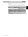
Chapter 1, Speed Transducer
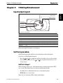
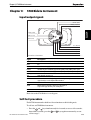
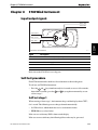
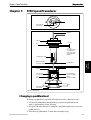
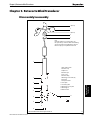
Chapter 1:
ST40 Speed Transducer
HAND
T
Insert (top view)
HTEN
IG
Arrow indicates
front of boat
Insert (side view)
Pull ring
Cap nut
3, 'O' ring
Key
4, 'O' ring
('O' rings should be
free of abrasions,
knicks, and cuts to
ensure watertight
integrity.)
1, Paddlewheel shaft
Housing (side view)
2, Paddlewheel
Speed
Transducer
Flat area of blade
faces front of boat
5, Snap ring
Keyway
Vane housing
(6, valve assembly)
Vane retainer pin
(6, valve assembly)
Vane
(6, valve assembly)
Spring
(6, valve assembly)
Hull
Arrow indicates
front of boat
ST40 Speed transducer
D4518-2
Changing a paddlewheel
To change a paddlewheel, refer to the ST40 Speed transducer illustration, and:
1. Use the new paddlewheel shaft from the spare parts kit to push out the old
shaft (1) approximately 5 mm (1/4 inch).
2. Grasp the end of the old shaft (1) with pliers and pull it straight out, to release the
paddlewheel (2).
3. Place the new paddlewheel (2) in the insert assembly cavity.
ST40 Instruments Service Manual 83149-2
3-1
Part 3 Transducer Servicing
IMPORTANT: Ensure that the flat surface of the paddlewheel blades face the
direction of the arrow on top of the insert assembly.
When the insert assembly is installed in the housing, the arrow on the top insert
cap and the water exposed flat surface of the housing should both face the front of
the vessel.
4. Tap the new shaft (1) into place until it is flush with the housing, ensuring that the
shaft enters the centre hole of the paddlewheel bearing. Failure to align the
bearing before inserting the shaft can result in bearing damage.
Changing the valve assembly
The transducer incorporates a self-sealing valve which minimizes the flow of water
into the vessel if the insert assembly is removed. When the insert assembly is
removed, the curved vane is activated by a spring and by water pressure, which push
the vane upward to seal the opening. The valve assembly is held in place with a
corrosion resistant snap ring.
WARNING:
Do NOT attempt to remove the self-sealing valve assembly when the vessel is in
the water, as the consequent inflow of water may cause the vessel to sink.
If the valve mechanism fails, ensure the vessel is not in the water, refer to the ST40
Speed transducer illustration, and carry out the following:
1. Remove the snap ring (5), using a screwdriver to pry the end of the ring free.
Speed
Transducer
2. Slide the valve assembly upward, out of the housing.
Note: The vane retainer pin is a loose slip-fit and may slide out when the assembly is
removed from the housing.
3. To install a valve assembly, insert it into the housing (vane tongue pointing
downward). Install the snap ring (5), making certain that it locks into its groove in
the housing wall.
ST40 Speed transducer spare parts list
The item numbers refer to the ST40 Speed transducer illustration.
3-2
Item
Spare/Accessory Description
Part No.
D234
1
2
3
4
5
6
Speed transducer service kit
comprising:
Paddlewheel shaft
Paddlewheel
‘O’ ring (x2)
‘O’ ring (x2)
Snap ring
Valve assembly
Comments
ST40 Instruments Service Manual 83149-2
Chapter 1, Speed Transducer
Insert assembly installation
When reinstalling the insert assembly:
• Ensure that the ‘O’ rings have been inspected and if necessary, replaced and
lubricated
• Ensure that the key of the insert assembly locates with the keyway of the housing
assembly.
• Secure with cap nut (hand tighten).
ST40 Speed transducer connections
Instrument head circuit
diagram reference
Description
Red
12V
Approximately 11.2 V dc out
Green
SPD
With transducer attached, spinning paddlewheel
produces pulses approximately 11.2 V dc in amplitude
at 5.5 Hz/knot.
Screen
0V
0V
White
TEMP
With transducer attached, voltage here is dependent
on temperature. Approximately 1.8 V at 0 degrees C.
Brown
0VANA
0V
Speed
Transducer
Cable core
colour
ST40 Instruments Service Manual 83149-2
3-3
Speed
Transducer
Part 3 Transducer Servicing
3-4
ST40 Instruments Service Manual 83149-2
Chapter 2, Fluxgate Compass Transducer
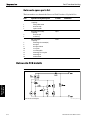
Chapter 2. ST40 Fluxgate Compass Transducer
Functional test
Disconnect the Fluxgate Compass from the instrument and check continuity as
follows:
Cable colour
Resistance
Screen to blue
< 10 ohms
Red to green
< 5 ohms
Red to yellow
< 5 ohms
Red to screen
Open circuit
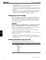
Magnetic deviation
The Fluxgate Compass requires careful siting to achieve optimum performance. The
instrument software is able to correct the compass for most deviating magnetic fields
present when the linearisation procedure is carried out. Any further deviation
introduced after linearisation, will introduce an error between the Fluxgate Compass
and the ship’s compass. This can be removed by carrying out the linearisation again.
If the displayed deviation is greater than +/– 15 degrees the Fluxgate should be
resited. For installation and calibration information, refer to the ST40 Compass
Instrument Owner’s Handbook.
Note: The linearisation procedure should always be carried out if the Fluxgate
Compass has been exchanged, or moved from its original mounting position.
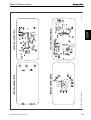
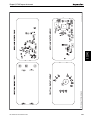
7
Connector Wiring Detail
Screen
Blue
Green
Red
Yellow
8
Hot melt glue
Cable tie
3
4
6
1. Cover
2. Seal
3. Pivot retaining screw (x2)
4. Bracket
5. Pivot sub-assembly
1
9
6. Fluxgate sub-assembly
7. Body
8. Body screw (x4)
9. Cable
2
Fluxgate Compass Transducer Exploded View
ST40 Instruments Service Manual 83149-2
5
D4519-2
3-5
Fluxgate Compass
Transducer
Disassembly/reassembly
Part 3 Transducer Servicing
Fluxgate Compass spare parts list
The item numbers refer to Figure 2: Fluxgate Compass exploded view
Item
Spare Description
Part No.
M096
3
4
Compass base kit
comprising:
Pivot retaining screw (x2)
Bracket
M022
5
6
Fluxgate sub-assembly
comprising:
Pivot sub-assembly (x2)
Fluxgate sub-assembly
Comments
ST40 Fluxgate Compass transducer connections
Instrument head circuit
diagram reference
Description
Red
VREF
Fluxgate 2.5 V
Yellow
FGA
Sense A
Green
FGB
Sense B
Blue
FGDRIVE
Fluxgate drive
White
SCREEN
Fluxgate 0 V return
Fluxgate Compass
Transducer
Cable core
colour
3-6
ST40 Instruments Service Manual 83149-2
Chapter 3, Rotavecta Wind Transducer
Chapter 3. Rotavecta Wind Transducer
Disassembly/reassembly
1 (Note A)
2
3 (Note A)
4
5
Note:
If the Allen grubsrew (1) is backed off too far,
the captive nut (3) can fall out. When disassembling,
unscrew the grubsrew just sufficiently to allow the
Rotavecta cups (2) to be pulled from the shaft.
6
1. Allen grubscrew M3
2. Rotavecta cups
8
9
Rotavecta Wind
Transducer
7
3. Captive nut
4. Rotavecta pod
5. Pod 'O' ring
6. Rotavecta body
7. Mounting pod screw M5 (x2)
8. Base plate
9. Base plate locknut
10. Cover plate
11. Connecting cable
12. Mounting pod cover plate
13. Mounting pod
14. Grubscrew M5
10
12
11
13
14
Rotavecta Wind Transducer Exploded View
ST40 Instruments Service Manual 83149-2
D4046-3
3-7
Part 3 Transducer Servicing
Rotavecta spare parts list
The item numbers are shown in the Rotavecta Wind Transducer Exploded View.
Item
Spare/Accessory Description
Part No.
D240
1
2
3
Rotavecta transducer kit
comprising:
Allen grubscrew M3
Rotavecta cups
Captive nut M3
Q113
4
5
Rotavecta pod assembly
comprising:
Rotavecta pod
Pod ‘O’ ring
D316
7
8
9
10
11
12
13
14
Rail mounting kit
comprising:
Mounting pod screw M5(x2)
Base plate
Base plate locknut
Cover plate
Connecting cable
Mounting pod cover plate
Mounting pod
Grubscrew M5
Comments
Rotavecta Wind
Transducer
Rotavecta PCB details
Rotavecta Circuit Diagram
3-8
D4050-3 (from Drwg. No. 4233-006-A)
ST40 Instruments Service Manual 83149-2
Chapter 3, Rotavecta Wind Transducer
Taken from Drawing No: 4233-001 Issue: C Date: 08.11.93
D4048-2
PCB component list
D4049-2
Taken from Drawing No: 4233-001 Issue: C Date: 08.11.93
Rotavecta connections
Signal name at
Rotavecta PCB
Signal name at
Instrument PCB
Description
Red
WIND1
ROTA+
Constant current source
Blue
WIND2
ROTA–
0V
Rotavecta Wind
Transducer
Cable core
colour
ST40 Instruments Service Manual 83149-2
3-9
Rotavecta Wind
Transducer
Part 3 Transducer Servicing
3-10
ST40 Instruments Service Manual 83149-2