1
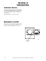
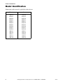
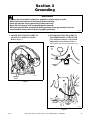
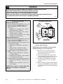
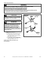
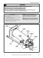
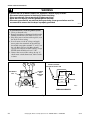
Service Commercial Stacked Dryers Metered and Nonmetered Refer to Page 3 for Model Numbers www.comlaundry.com Part No. 53277R2 January 2002 Table of Contents Section 1 – Safety Information Locating an Authorized Servicer ............................4 Section 2 – Introduction Customer Service ....................................................5 Nameplate Location ................................................5 Model Identification ................................................6 How Your Dryer Works ..........................................7 Section 3 – Grounding 1. Motor Mounting Bracket To Motor (Gas and Electric Models) ...............................................9 2. Motor Mounting Bracket to Blower Housing Cover Plate .......................................................9 3. Neutral at Terminal Block to Terminal Block Bracket And From Terminal Bracket to Control (Electric Models Only) ...................................10 4. Power Cord to Terminal Block Bracket and From Terminal Block Bracket to Control Housing. Wall Receptacle Polarity Check (Gas Models Only) ..............................................................10 5. From Terminal Block Bracket to Accumulator bracket or Timer (Depending on Model) to Cabinet Top to Control Panel (Metered and NonMetered Models ) ...........................................11 6. From Terminal Block Bracket to Cabinet Top, From Cabinet Top to Timer and Cabinet Top to Control Panel (Card Reader Models) .............11 Section 4 – Service Procedures 7. Control Panel ...................................................13 8. Accumulator .....................................................13 9. Push-To-Start Switch .......................................16 10. Temperature Selector Switch .........................16 11. Front Panel and Panel Seal ............................17 12. Door Switch ...................................................17 13. Indicator Light ...............................................18 14. Loading Door .................................................18 15. Inner and Outer Door Panels and Door Handle ............................................18 16. Door Striker ...................................................18 17. Striker Catch ..................................................18 18. Door Hinge And Support Bracket ..................18 19. Door Seal .......................................................18 20. Lint Filter .......................................................19 21. Hold-Down clips and Guide Lugs .................19 22. 23. 24. 25. 26. 27. 28. 29. 30. 31. 32. 33. 34. 35. 36. 37. 38. 39. 40. 41. 42. 43. 44. 45. 46. Terminal Block or Power Cord ......................19 Burner System Operation ...............................21 Ignition System Features ...............................21 Burner System Components (Gas Models) Silicon Carbide (Glow Bar) Ignition ..............22 Burner Housing ..............................................27 Heat Shroud ...................................................27 Heat Element ..................................................27 High or Low thermostat .................................28 Limit Thermostat ...........................................28 Front Air duct .................................................29 Exhaust Duct ..................................................29 Exhaust Fan Cover .........................................29 Motor and Exhaust Assembly ........................30 Impeller and Housing .....................................31 Motor .............................................................32 Motor And Idler Pulley Assemblies ..............33 Front Bulkhead Assembly .............................33 Cylinder Belt ..................................................34 Cylinder Assembly ........................................35 Rear Seal ........................................................35 Cylinder Rollers and Roller Shaft ..................36 Rear Bulkhead and Heater Box .....................36 Heat Shield .....................................................37 Rear Mounting Brackets ................................37 Cabinet and Base ...........................................37 Section 5 – Adjustments 47. Leveling Legs ................................................39 48. Burner Flame (Gas Models) ..........................40 Section 6 – Gas Burner Conversion Procedures 49. No. 458P3 L.P. Gas Conversion Kit for “EG” Models/Series Dryers ...........................41 50. Installing The No. 458P3 Kit .........................42 51. No. 459P3 Natural Gas Conversion Kit for “EG” Models/Series Dryers ...........................45 52. Installing The No. 459P3 Kit .........................46 © Copyright 2002, Alliance Laundry Systems LLC All rights reserved. No part of the contents of this book may be reproduced or transmitted in any form or by any means without the expressed written consent of the publisher. 53277 © Copyright, Alliance Laundry Systems LLC – DO NOT COPY or TRANSMIT 1 Section 1 Safety Information Throughout this manual and on machine decals, you will find precautionary statements (“CAUTION,” “WARNING,” and “DANGER”) followed by specific instructions. These precautions are intended for the personal safety of the operator, user, servicer, and those maintaining the machine. a DANGER Danger indicates the presence of a hazard that will cause severe personal injury, death, or substantial property damage if the danger is ignored. a WARNING Warning indicates the presence of a hazard that can cause severe personal injury, death, or substantial property damage if the warning is ignored. a CAUTION Caution indicates the presence of a hazard that will or can cause minor personal injury or property damage if the caution is ignored. Additional precautionary statements (“IMPORTANT” and “NOTE”) are followed by specific instructions. IMPORTANT The word “IMPORTANT” is used to inform the reader of specific procedures where minor machine damage will occur if the procedure is not followed. NOTE The word “NOTE” is used to communicate installation, operation, maintenance or servicing information that is important but not hazard related. In the interest of safety, some general precautions relating to the operation of this machine follow. WARNING • Failure to install, maintain and/or operate this product according to the manufacturer’s instructions may result in conditions which can produce serious injury, death and/or property damage. • Do not repair or replace any part of the product or attempt any servicing unless specifically recommended or published in this Service Manual and that you understand and have the skills to carry out. • Whenever ground wires are removed during servicing, these ground wires must be reconnected to ensure that the product is properly grounded and to reduce the risk of fire, electric shock, serious injury or death. W006R1 53277 © Copyright, Alliance Laundry Systems LLC – DO NOT COPY or TRANSMIT 3 Section 1 Safety Information WARNING To reduce the risk of electric shock, fire, explosion, serious injury or death: • Disconnect electric power to the dryer(s) before servicing. • Close gas shut-off valve to gas dryer(s) before servicing. • Never start the dryer(s) with any guards/panels removed. • Whenever ground wires are removed during servicing, these ground wires must be reconnected to ensure that the dryer is properly grounded. W001R1 WARNING Repairs that are made to your products by unqualified persons can result in hazards due to improper assembly or adjustments subjecting you, or the inexperienced person making such repairs, to the risk of serious injury, electrical shock or death. W007 WARNING If you or an unqualified person perform service on your product, you must assume the responsibility for any personal injury or property damage which may result. The manufacturer will not be responsible for any injury or property damage arising from improper service and/or service procedures. W008 NOTE: The WARNINGS and IMPORTANT INSTRUCTIONS appearing in this manual are not meant to cover all possible conditions and situations that may occur. Common sense, caution and care must be exercised when installing, maintaining or operating the dryer. Always contact your dealer, distributor, service agent or the manufacturer about any problems or conditions you do not understand. Locating an Authorized Servicer Alliance Laundry Systems is not responsible for personal injury or property damage resulting from improper service. Review all service information before beginning repairs. Warranty service must be performed by an authorized technician, using authorized factory parts. If service is required after the warranty expires, Alliance Laundry Systems also recommends contacting an authorized technician and using authorized factory parts. 4 © Copyright, Alliance Laundry Systems LLC – DO NOT COPY or TRANSMIT 53277 Section 2 Introduction Customer Service If literature or replacement parts are required, contact the source from whom the machine was purchased or contact Alliance Laundry Systems at (920) 748-3950 for the name and address of the nearest authorized parts distributor. For technical assistance, call (920) 748-3121. Nameplate Location When calling or writing about your product, be sure to mention model and serial numbers. Model and serial numbers are located on nameplate(s) as shown. DRY912P NAMEPLATE 53277 © Copyright, Alliance Laundry Systems LLC – DO NOT COPY or TRANSMIT 5 Section 2 Introduction Model Identification Information in this manual is applicable to these dryers. 6 Electric Gas SE5130 RE6332 RE6330 RE6232 RE6132 RE6130 RE5232 RE5230 RE5132 RE5130 EE5511 EE5510 EE5111 EE5110 EE1510 SG5190 RG6392 RG6390 RH6292 RH6192 RG6190 RG5292 RG5290 RG5192 RG5190 EG5121 EG5120 EG5020 EG5010 EG1520 © Copyright, Alliance Laundry Systems LLC – DO NOT COPY or TRANSMIT 53277 Section 2 Introduction How Your Dryer Works CYLINDER LINT FILTER HEATER DUCT EXHAUST FAN DRY14S The dryer uses heated air to dry loads of laundry. When the motor is started, the exhaust fan pulls air in through louvers at the rear of the dryer and over the heat source (burner flame for gas and heating element for electric). The heated air moves through the heater duct and into the cylinder, where it circulates through the wet load. The air then passes through the lint filter, air duct, and exhaust fan, where it is vented to the outdoors. 53277 © Copyright, Alliance Laundry Systems LLC – DO NOT COPY or TRANSMIT 7 Section 3 Grounding WARNING To reduce the risk of electric shock, fire, explosion, serious injury or death: • Disconnect electric power to the dryer(s) before servicing. • Close gas shut-off valve to gas dryer(s) before servicing. • Never start the dryer(s) with any guards/panels removed. • Whenever ground wires are removed during servicing, these ground wires must be reconnected to ensure that the dryer is properly grounded. W001R1 1. MOTOR MOUNTING BRACKET TO MOTOR (Gas and Electric Models) Refer to Figure 1 2. MOTOR MOUNTING BRACKET TO BLOWER HOUSING COVER PLATE (Gas and Electric Models - with painted Exhaust Fan Cover) Refer to Figure 2 (Ground wire not used on unpainted covers) GROUND WIRE DRY832S GROUND WIRE Figure 1 GROUND WIRE DRY833S Figure 2 53277 © Copyright, Alliance Laundry Systems LLC – DO NOT COPY or TRANSMIT 9 Section 3 Grounding WARNING To reduce the risk of electric shock, fire, explosion, serious injury or death: • Disconnect electric power to the dryer(s) before servicing. • Close gas shut-off valve to gas dryer(s) before servicing. • Never start the dryer(s) with any guards/panels removed. • Whenever ground wires are removed during servicing, these ground wires must be reconnected to ensure that the dryer is properly grounded. W001R1 3. NEUTRAL AT TERMINAL BLOCK TO TERMINAL BLOCK BRACKET AND FROM TERMINAL BRACKET TO CONTROL (Electric Models Only) Refer to Figure 3 GROUND WIRE DRY834S Figure 3 4. POWER CORD TO TERMINAL BLOCK BRACKET AND FROM TERMINAL BLOCK BRACKET TO CONTROL HOUSING. WALL RECEPTACLE POLARITY CHECK (Gas Models Only) Refer to Figure 4 NOTE: For determining the correct polarity of a wall receptacle. NEUTRAL SIDE GROUND NEUTRAL L1 0 V.A.C. 120 V.A.C. GROUND WIRE 120 V.A.C. DRY945S Figure 4 10 © Copyright, Alliance Laundry Systems LLC – DO NOT COPY or TRANSMIT 53277 Section 3 Grounding WARNING To reduce the risk of electric shock, fire, explosion, serious injury or death: • Disconnect electric power to the dryer(s) before servicing. • Close gas shut-off valve to gas dryer(s) before servicing. • Never start the dryer(s) with any guards/panels removed. • Whenever ground wires are removed during servicing, these ground wires must be reconnected to ensure that the dryer is properly grounded. W001R1 5. FROM TERMINAL BLOCK BRACKET TO ACCUMULATOR BRACKET OR TIMER (Depending on Model) TO CABINET TOP TO CONTROL PANEL (Metered and Non-Metered Models ) GROUND WIRE DRY946S Figure 5 6. FROM TERMINAL BLOCK BRACKET TO CABINET TOP, FROM CABINET TOP TO TIMER AND CABINET TOP TO CONTROL PANEL (Card Reader Models) GROUND WIRE GROUND WIRE DRY947S Figure 6 53277 © Copyright, Alliance Laundry Systems LLC – DO NOT COPY or TRANSMIT 11 Section 4 Service Procedures WARNING To reduce the risk of electric shock, fire, explosion, serious injury or death: • Disconnect electric power to the dryer(s) before servicing. • Close gas shut-off valve to gas dryer(s) before servicing. • Never start the dryer(s) with any guards/panels removed. • Whenever ground wires are removed during servicing, these ground wires must be reconnected to ensure that the dryer is properly grounded. W001R1 FABRIC SELECTOR SWITCH (Lower Dryer) PUSH-TO-START SWITCH (Upper Dryer) PUSH-TO-START SWITCH (Lower Dryer) FABRIC SELECTOR SWITCH (Upper Dryer) DRY948S UNLOCK AND LIFT UP SWING BOTTOM OUT PULL DOWN AND AWAY Figure 7 IMPORTANT: When reference to direction (right or left) is made in this manual, it is from the operator’s position facing the front of the dryer. 7. CONTROL PANEL Refer to Figure 7 a. Unlock control panel. b. Lift up on control panel and swing bottom of control panel out, then pull down and away from control cabinet. 8. ACCUMULATOR Refer to Figure 8 a. Remove control panel. Refer to Paragraph 7. b. Reach in through control panel opening and remove screws holding accumulator and mounting bracket to control cabinet. c. Disconnect wires from accumulator. 53277 NOTE: Refer to appropriate wiring diagram when rewiring accumulator. ACCUMULATOR ATTACHING SCREWS ON DRY449S Figure 8 © Copyright, Alliance Laundry Systems LLC – DO NOT COPY or TRANSMIT 13 Section 4 Service Procedures WARNING To reduce the risk of electric shock, fire, explosion, serious injury or death: • Disconnect electric power to the dryer(s) before servicing. • Close gas shut-off valve to gas dryer(s) before servicing. • Never start the dryer(s) with any guards/panels removed. • Whenever ground wires are removed during servicing, these ground wires must be reconnected to ensure that the dryer is properly grounded. W001R1 To Test Accumulator and Timer Motor Metered Models Refer to Figure 9 1. Remove service door, accumulator and timing motor assembly. 2. Remove wires from one side of each switch. NOTE: Refer to appropriate wiring diagram when rewiring timer. 3. Manaully advance timing cam to disengage it from ratchet wheel. 4. Set meter to read Ohms and apply leads on terminals of each switch in turn. You should read the following: Switch A = “zero ohms (closed). Switch B = “zero” ohms (closed). Switch C (if present) = “infinite” (open) 5. Manually advance timing cam until it engages with ratchet wheel and the first “click” is heard. Switch B should now read “ifinite” (open). 6. Continue to rotate timing cam until second “click” is heard. Switch B should remain open. Switch A should read “infinite” 9open) and Swtich C (if present) should read “zero” Ohms (closed). 7. Timing Motor Apply live power to timing motor leads - Timing motor should advance timing cam. RATCHET WHEEL TIMING CAM RATCHET WHEEL DRY958S SWITCH LEVER SWITCHES SWITCH LEVER 3 Switch Accumulator DRY959S 2 Switch Accumulator Figure 9 14 © Copyright, Alliance Laundry Systems LLC – DO NOT COPY or TRANSMIT 53277 Section 4 Service Procedures WARNING To reduce the risk of electric shock, fire, explosion, serious injury or death: • Disconnect electric power to the dryer(s) before servicing. • Close gas shut-off valve to gas dryer(s) before servicing. • Never start the dryer(s) with any guards/panels removed. • Whenever ground wires are removed during servicing, these ground wires must be reconnected to ensure that the dryer is properly grounded. W001R1 To Test Timer Contact Points Nonmetered Models Refer to Figure 10 1. Remove four screws and lockwashers holding timer and plate to timer case. L1 H NOTE: When installing timer plat,e lockwashers must be between head of screw and late. N 2. Pull timer plate out of timer case as far as wire will permit. 3. Remove screw, lockwasher and locknut holding ground wires from timer. 4. Disconnect wires from timer, except timer motor. NOTE: Refer to appropriate wiring diagram when rewiring timer. 5. Manually rotate timer out of “OFF” position and into cycle. 6. Set meter to read Ohms and put meter probes to terminals: a. Motor circuit test - L1 and M = “zero ohms (closed). b. Heat circuit test - L1 and H = “zero” ohms (closed). c. Timer Motor test - L1 and N = approximately 1100 Ohms or apply live power to timer motor terminals and motor should run. 7. Rotate timer to “cooldown” (5 minutes before “OFF”). “Infinite” (open) reading should be found between L1 and H. 8. Rotate timer to “OFF” position. “Infinite” (open) reading should be found between L1 and M and between L1 and H. DRY957S Figure 10 NOTE: Timer motor power is supplied through M terminal. 53277 © Copyright, Alliance Laundry Systems LLC – DO NOT COPY or TRANSMIT 15 Section 4 Service Procedures WARNING To reduce the risk of electric shock, fire, explosion, serious injury or death: • Disconnect electric power to the dryer(s) before servicing. • Close gas shut-off valve to gas dryer(s) before servicing. • Never start the dryer(s) with any guards/panels removed. • Whenever ground wires are removed during servicing, these ground wires must be reconnected to ensure that the dryer is properly grounded. W001R1 9. PUSH-TO-START SWITCH Refer to Figure 7 a. Remove control panel. Refer to Paragraph 7. 10. TEMPERATURE SELECTOR SWITCH Refer to Figure 7 a. Remove control panel. Refer to Paragraph 7. NOTE: Refer to appropriate wiring diagram when rewiring accumulator. NOTE: Refer to appropriate wiring diagram when rewiring accumulator. 1. 2. 3. 4. 5. 6. To Test Push-To-Start Switch Remove two control panel attaching screws and lift assembly off cabinet top. Disconnect all wires from switch. Set Volt-Ohm meter on Ohms scale and calibrate at appropriate scale. Unplug dryer from electrical supply and disconnect wires from switch terminals. Place meter probes on switch terminals. You should see an “infinite” reading on the meter. With probes attached to switch, press the start switch button. You should read “0” (zero) Ohms. To Test Fabric Switch: 1. Disconnect wires from switch. NOTE: Refer to appropriate wiring diagram when rewiring switch. 2. Set meter to read Ohms and apply meter leads to terminals: L1 and C L1 and 2 “zero” reading in NOMAL 2 and C L2 and C “zero” reading in PERMANENT PRESS 2 and C L1 and 2 “zero” reading in DELICATE 2 and 1 3. Meter should give “no reading” from L1 to C or from L2 to C in DeLICATE or FLUFF. 4. Meter should give “no reading” from C to 1 in DELICATE. 16 © Copyright, Alliance Laundry Systems LLC – DO NOT COPY or TRANSMIT 53277 Section 4 Service Procedures WARNING To reduce the risk of electric shock, fire, explosion, serious injury or death: • Disconnect electric power to the dryer(s) before servicing. • Close gas shut-off valve to gas dryer(s) before servicing. • Never start the dryer(s) with any guards/panels removed. • Whenever ground wires are removed during servicing, these ground wires must be reconnected to ensure that the dryer is properly grounded. W001R1 11. FRONT PANEL AND PANEL SEAL IMPORTANT: Do not move dryer unit when lower front panel is not in place. a. Remove two screws from bottom edge of front panel. b. On upper unit, swing bottom of panel away from dryer to disengage hold-down clips from slots in cabinet top. c. On lower unit, swing bottom of panel away from dryer to disengage guide lugs from control cabinet. d. Disconnect wires from door switch and indicator light. 12. DOOR SWITCH a. Remove front panel. Refer to Paragraph 11, steps “a” through “c”. b. Depress tabs on top and bottom of switch and push out toward front of panel. c. Disconnect wires from door switch. Refer to Figure 11. NOTE: Refer to appropriate wiring diagram when rewiring switch.) NOTE: Refer to appropriate wiring diagram when reconnecting wires. e. Remove front panel seal from flange around inside of door opening. NOTE: Be sure seal is properly positioned when installing on front panel. Ribbed side of seal should be against inside of front panel. D240S Figure 11 To Test Door Switch: 1. Disconnect wires from door switch. NOTE: Refer to appropriate wiring diagram when rewiring switch. 2. Set meter to read Ohms and apply meter probes on switch terminals with door closed. You should get “zero” reading. 3. Open door. Meter should read “infinite. 53277 © Copyright, Alliance Laundry Systems LLC – DO NOT COPY or TRANSMIT 17 Section 4 Service Procedures WARNING To reduce the risk of electric shock, fire, explosion, serious injury or death: • Disconnect electric power to the dryer(s) before servicing. • Close gas shut-off valve to gas dryer(s) before servicing. • Never start the dryer(s) with any guards/panels removed. • Whenever ground wires are removed during servicing, these ground wires must be reconnected to ensure that the dryer is properly grounded. W001R1 13. INDICATOR LIGHT Refer to Figure 7 a. Remove front panel. Refer to Paragraph 11. b. compress locking tabs and push light out of front of panel. IMPORTANT: Pressing on center of lens when installing lens may break the lens. Insert light into front panel by pressing firmly against trim. 14. LOADING DOOR a. Remove four screws holding hinges to door. Refer to Figure 12. 16. DOOR STRIKER Refer to Figure 13 a. Remove two screws holding handle to door. b. Spread door panels just far enough to depress tabs on top and bottom of striker and push out of inner panel. 17. STRIKER CATCH a. Remove front panel. Refer to Paragraph 11. b. Depress tabs on top and bottom of catch and push out of front panel. 18. DOOR HINGE AND SUPPORT BRACKET a. Remove front panel. Refer to Paragraph 11. b. Remove loading door. Refer to Paragraph 14. c. Remove four Phillips head screws and locknuts holding hinges to front panel. NOTE: Through Serial No. S70U4371, support bracket is removed with lower hinge. Support bracket must be installed when reassembling. 19. DOOR SEAL Refer to Figure 13 a. Open loading door and remove seal from inner door panel. NOTE: When installing seal, be sure seal is not stretched or distorted. Use a heat resistant adhesive to adhere door seal to inner door panel. DRY849 Figure 12 15. INNER AND OUTER DOOR PANELS AND DOOR HANDLE Refer to Figure 13 a. Remove loading door. Refer to Paragraph 14. b. Remove screws holding handle to door and separate panels. Refer to Figure 13. 18 © Copyright, Alliance Laundry Systems LLC – DO NOT COPY or TRANSMIT 53277 Section 4 Service Procedures WARNING To reduce the risk of electric shock, fire, explosion, serious injury or death: • Disconnect electric power to the dryer(s) before servicing. • Close gas shut-off valve to gas dryer(s) before servicing. • Never start the dryer(s) with any guards/panels removed. • Whenever ground wires are removed during servicing, these ground wires must be reconnected to ensure that the dryer is properly grounded. W001R1 DOOR HANDLE SCREW DOOR STRIKER DOOR SEAL DOOR HANDLE SCREW DOOR SEAL DOOR HANDLE DOOR HANDLE DOOR STRIKER INNER DOOR PANEL INNER DOOR PANEL OUTER DOOR PANEL OUTER DOOR PANEL HINGE HINGE DRY938P DRY850S Figure 13 20. LINT FILTER Refer to Figure 10 a. Open loading door and remove two screws holding lint filter to dryer air duct. b. Lift filter out of air duct. NOTE: When installing lint filter be sure stamped “front” of filter faces front of dryer. If installing a new style white lint filter for the first time, use an awl or screw to push out the perforated holes. 21. HOLD-DOWN CLIPS AND GUIDE LUGS a. Remove front panel. Refer to Paragraph 11. b. On upper unit, compress hold-down clips and remove from slots in top flange of front panel. c. Remove screws holding guide lugs to front panel. 22. TERMINAL BLOCK OR POWER CORD Refer to Figure 14 a. Terminal Block - Electric Models (1) Remove access plate on rear of dryer. (2) Remove all wires from terminal block. 53277 NOTE: Refer to appropriate wiring diagram when rewiring block. (3) Remove screws holding terminal block to bracket and remove terminal block. NOTE: Do not let terminal block insulation drop when removing the block. Insulation must be in place between terminal block and bracket when installing block. b. Terminal Block with Spade (Starting Serial No. S6270866XG) (1) Remove front panel. Refer to Paragraph 11. (2) Remove all wires from terminal block. NOTE: Refer to appropriate wiring diagram when rewiring block. (3) Remove screws holding terminal block to bracket and remove terminal block. © Copyright, Alliance Laundry Systems LLC – DO NOT COPY or TRANSMIT 19 Section 4 Service Procedures WARNING To reduce the risk of electric shock, fire, explosion, serious injury or death: • Disconnect electric power to the dryer(s) before servicing. • Close gas shut-off valve to gas dryer(s) before servicing. • Never start the dryer(s) with any guards/panels removed. • Whenever ground wires are removed during servicing, these ground wires must be reconnected to ensure that the dryer is properly grounded. W001R1 NOTE: Do not let terminal block insulation drop when removing the block. Insulation must be in place between terminal block and bracket when installing block. (4) Disconnect power cord at quick disconnect plug and remove power cord out through rear of dryer. TERMINAL BLOCK SCREWS WASHER PHILLIPS HEAD SCREW APPLY PRESSURE HERE ACCESS PLATE BRACKET SCREWS GROUND WIRE DRY950S Figure 14 SUPPORT ACCESS DOOR DRY951S Figure 15 c. Power Cord - Gas Models (1) Remove access plate at rear of dryer. (2) Remove strain relief holding power cord to cabinet. (3) Remove screw holding power cord ground wire to terminal block bracket. NOTE: Reconnect ground wire into same hole in bracket when reinstalling power cord. 20 © Copyright, Alliance Laundry Systems LLC – DO NOT COPY or TRANSMIT 53277 Section 4 Service Procedures WARNING To reduce the risk of electric shock, fire, explosion, serious injury or death: • Disconnect electric power to the dryer(s) before servicing. • Close gas shut-off valve to gas dryer(s) before servicing. • Never start the dryer(s) with any guards/panels removed. • Whenever ground wires are removed during servicing, these ground wires must be reconnected to ensure that the dryer is properly grounded. W001R1 23. BURNER SYSTEM OPERATION Refer to Figure 20 a. Components (1) This burner has four basic components: (a.) A silicon carbide (glow bar) igniter (b.) Burner tube (c.) Flame sensor (d.) Two-stage gas valve consisting of a split-coil valve and a secondary coil valve. (2) The split-coil valve is opened when the dryer thermostat calls for heat, while the secondary valve does not open until the igniter has attained ignition temperature. b. Pre-Ignition Circuits (a.) When the dryer thermostat calls for heat, circuits are completed through the holding coil, flame sensor, booster coil and igniter. (b.) Both coils must be energized to open split-coil valve. (c.) Once opened, the holding coil can hold the valve open without assistance from the booster coil. (d.) The current shunted around the secondary coil by the flame sensor, passes through the igniter causing it to get hot. c. Burn Circuit (1) In approximately 30 seconds, the igniter attains ignition temperature and the flame sensor (located on burner housing beside the igniter) contacts open. (2) A circuit is then completed through the secondary coil, opening the valve and allowing gas to flow. (3) Ignition is made and the heat from the burner flame causes the flame sensor contacts to remain open. 53277 24. IGNITION SYSTEM FEATURES Refer to Figure 20 a. Momentary Power Interruption (1) Upon resumption of power, flame sensor contacts will still be open, permitting secondary valve to open. (2) However, with the secondary coil in the circuit, the booster coil cannot draw enough current to open the split-coil valve. (3) When flame sensor contacts do reclose, the secondary valve will close, and the burner system will be in the normal pre-ignition circuit. b. Flame Failure (1) In case of flame failure, the flame sensor contacts will reclose in about 45 seconds. (2) This will close the secondary valve and the burner system will be in the normal preignition circuit. c. Ignition Failure (1) If flame is not established as flame sensor contacts open, secondary valve will remain open until flame sensor contacts reclose. (2) Flame sensor will continue to recycle the igniter and secondary valve (about once per minute) until ignition is made or dryer is turned off. © Copyright, Alliance Laundry Systems LLC – DO NOT COPY or TRANSMIT 21 Section 4 Service Procedures WARNING To reduce the risk of electric shock, fire, explosion, serious injury or death: • Disconnect electric power to the dryer(s) before servicing. • Close gas shut-off valve to gas dryer(s) before servicing. • Never start the dryer(s) with any guards/panels removed. • Whenever ground wires are removed during servicing, these ground wires must be reconnected to ensure that the dryer is properly grounded. W001R1 (3) Loosen union nut between gas shutoff valve and nipple connector to gas valve. Unthread nut from nipple completely. Refer to Figure 16. (4) Remove screws holding valve and bracket to base. Refer to Figure 16. (5) Lift gas valve and mounting bracket from base and carefully remove through front of dryer. 25. BURNER SYSTEM COMPONENTS (Gas Models) SILICON CARBIDE (GLOW BAR) IGNITION a. Complete gas valve assembly. (1) Remove front panel. Refer to Paragraph 11. (2) Close gas shutoff valve and disconnect wires from sensor and at quick disconnect blocks. Refer to Figure 16. NOTE: Refer to appropriate wiring diagram when rewiring gas valve. SCREW HEAT SHROUD BURNER HOUSING LIMIT THERMOSTAT BURNER TUBE SCREW SENSOR ATTACHING SCREW DISCONNECT BLOCK INLET TUBE FLAME SENSOR TAB NIPPLE VALVE D241S UNION NUT Figure 16 22 © Copyright, Alliance Laundry Systems LLC – DO NOT COPY or TRANSMIT 53277 Section 4 Service Procedures WARNING To reduce the risk of electric shock, fire, explosion, serious injury or death: • Disconnect electric power to the dryer(s) before servicing. • Close gas shut-off valve to gas dryer(s) before servicing. • Never start the dryer(s) with any guards/panels removed. • Whenever ground wires are removed during servicing, these ground wires must be reconnected to ensure that the dryer is properly grounded. W001R1 53277 4 SECONDARY COIL 5 1 1 - 3 NOTE: If meter registers any other readings than listed above, the respective coil should be replaced. TOP VIEW OF GAS VALVE 4 5 To Test Gas Valve Coils: Models starting Serial No. ________ 1. Remove disconnect blocks from gas valve coils. 2. Set test meter to read OHMS and put meter probes to terminals as follows: (Refer to Figure 17.) a. Holding Coil - Terminals 1 and 2 - Meter should read 1365 ± 25 Ohms. b. Booster Coil - Terminals 1 and 2 - Meter should read 560 ± 25 Ohms. c. Secondary Coil - Terminals 4 and 5 - Meter should rear 1220 ± 50 Ohms. Models through Serial No. ___________ 1. Remove disconnect blocks from gas valve coils. 2. Set test meter to read OHMS and put meter probes to terminals as follows. 3. Connect Ohmeter between black and blue wires - 120 volt power supply. a. Reading 567 to 694 Ohms - All coils are OK. b. Reading 1100 to 1430 Ohms - Move Ohmeter to white and blue sensor wires. 4. Connect Ohmeter to white and blue sensor wires. a. Reading 1640 to 2010 Ohms - Secondary coil open - Replace. b. Reading 630 to 770 Ohms - Move Ohmeter to red and black igniter wires. 5. Connect Ohmeter to red and black igniter wires. a. Reading 540 to 660 Ohms - Hold coil open replace. b. Reading 1730 to 2120 Ohms - Boost coil open - Replace. 2 3 D270S HOLDING AND BOOSTER COIL Figure 17 b. Burner tube and igniter. NOTE: Burner tube and igniter can be removed without removing gas valve and bracket. (1) Remove one screw from right side of burner housing holding burner tube in place. Refer to Figure 16. (2) Gently move burner tube toward rear of dryer to disengage tab from slot on left side of burner housing. Refer to Figure 16. (3) Carefully rotate burner tube and igniter counterclockwise so tab is at 8 o’clock position. (4) Move air shutter end of burner tube slightly to right and CAREFULLY remove burner tube and igniter assembly out through front of dryer. © Copyright, Alliance Laundry Systems LLC – DO NOT COPY or TRANSMIT 23 Section 4 Service Procedures WARNING To reduce the risk of electric shock, fire, explosion, serious injury or death: • Disconnect electric power to the dryer(s) before servicing. • Close gas shut-off valve to gas dryer(s) before servicing. • Never start the dryer(s) with any guards/panels removed. • Whenever ground wires are removed during servicing, these ground wires must be reconnected to ensure that the dryer is properly grounded. W001R1 CAUTION CARBORUNDUM IGNITER AND BRACKET ATTACHING SCREW Use care in removal so as not to damage or break igniter as it is very fragile. WARNING Handle igniter by grasping white ceramic portions only. DO NOT handle silicon carbide portion of igniter with hands or allow any oil, grease or other foreign material to contaminate it. Oil, grease and other impurities or hairline cracks will cause igniter to burn out. c. Igniter. Refer to Figure 18 (1) Remove burner tube and igniter, step “b”. (2) If 55438 igniter, remove by carefully spreading mounting clip with snap ring pliers. Refer to Figure 18. (3) If 58823 igniter, remove Phillips head screw holding igniter and ceramic block to burner tube. Refer to Figure 18. 58823 IGNITER AND BRACKET ATTACHING SCREW NORTON IGNITER AND BRACKET DRY952S Figure 18 NOTE: Igniters 55438 and 58823 are not interchangeable. 24 © Copyright, Alliance Laundry Systems LLC – DO NOT COPY or TRANSMIT 53277 Section 4 Service Procedures WARNING To reduce the risk of electric shock, fire, explosion, serious injury or death: • Disconnect electric power to the dryer(s) before servicing. • Close gas shut-off valve to gas dryer(s) before servicing. • Never start the dryer(s) with any guards/panels removed. • Whenever ground wires are removed during servicing, these ground wires must be reconnected to ensure that the dryer is properly grounded. W001R1 IMPORTANT: Always examine all wires, terminals and connectors to be sure wiring is proper before replacing any components. To Test Igniter: 1. Disconnect igniter wires at disconnect block. Refer to Figure 19. 2. Set test meter to read Ohms and put meter probes on terminals of igniter wires. 3. Meter should register an Ohm reading of at least 40 Ohms at the minimum. If meter registers less than 40 Ohms, replace the igniter. NOTE: Test procedure can be performed on workbench if gas valve, igniter, burner tube and burner housing have been removed from dryer. SCREW HEAT SHROUD BURNER HOUSING LIMIT THERMOSTAT BURNER TUBE SCREW SENSOR ATTACHING SCREW DISCONNECT BLOCK INLET TUBE FLAME SENSOR TAB NIPPLE VALVE D241S UNION NUT Figure 19 53277 © Copyright, Alliance Laundry Systems LLC – DO NOT COPY or TRANSMIT 25 Section 4 Service Procedures WARNING To reduce the risk of electric shock, fire, explosion, serious injury or death: • Disconnect electric power to the dryer(s) before servicing. • Close gas shut-off valve to gas dryer(s) before servicing. • Never start the dryer(s) with any guards/panels removed. • Whenever ground wires are removed during servicing, these ground wires must be reconnected to ensure that the dryer is properly grounded. W001R1 To Test Electrical Circuit to Ignition System: 1. Close gas shut-off valve. 2. Remove wire harness disconnect block from the Holding and Booster Coil. Refer to Figure 20. 3. Plug dryer power cord into wall receptacle, start the dryer in a heat setting. 4. Set test meter to read AC voltage and apply meter probes into terminals on dryer harness that would corespond to terminal “1” and “2” on the coil. Refer to Figure 20. Meter should register line voltage in all fabric settings, except FLUFF which should read “zero” VAC. 5. If meter does not read line voltage in step “4”, check motor switch, thermostats, fabric switch or timer. 1 SECONDARY COIL 2 3 120 VOLT, 60 HERTZ ELECTRICAL SUPPLY LINE HOLDING AND BOOSTER COIL SECONDARY COIL SENSOR HOLDING COIL BOOSTER COIL IGNITOR D268S D267S WIRING SCHEMATIC Figure 20 26 © Copyright, Alliance Laundry Systems LLC – DO NOT COPY or TRANSMIT 53277 Section 4 Service Procedures WARNING To reduce the risk of electric shock, fire, explosion, serious injury or death: • Disconnect electric power to the dryer(s) before servicing. • Close gas shut-off valve to gas dryer(s) before servicing. • Never start the dryer(s) with any guards/panels removed. • Whenever ground wires are removed during servicing, these ground wires must be reconnected to ensure that the dryer is properly grounded. W001R1 d. Sensor. Refer to Figure 16 NOTE: Flame sensor can be removed without removing gas valve and bracket. (1) Remove front panel. Refer to Paragraph 11. (2) Close gas shutoff valve. (3) Remove wires from sensor terminals. NOTE: Refer to appropriate wiring diagram when rewiring sensor. (4) Remove screw holding sensor to burner housing. To Test Sensor: 1. Remove wires from sensor terminals. Refer to Figure 19. 2. Set test meter to read Ohms and put meter probes on sensor terminals. Meter should read “zero” Ohms. If meter registers an Ohm reading of any amount, replace sensor. e. Limit Thermostat. Refer to Figure 16. NOTE: Limit thermostat can be removed without removing gas valve and bracket. (1) Remove front panel. Refer to Paragraph 11. (2) Remove wires from thermostat. 26. BURNER HOUSING a. Remove front panel. Refer to Paragraph 11. b. Remove gas valve and burner tube assemblies. Refer to Paragraph 25, steps “a” and “b”. c. If present, remove screw attaching burner housing to dryer base. Refer to Figure 22. d. Remove screw holding burner housing to heat shroud and pull burner housing out through front of dryer. 27. HEAT SHROUD a. Remove front panel and burner housing. Refer to Paragraph 26. b. Remove four screws holding shroud to heater box and pull shroud out through front of dryer. 28. HEAT ELEMENT a. Remove front panel. Refer to Paragraph 11. b. Remove two hex head screws holding element and plate to heater box and pull element down and away from heater box. Refer to Figure 22. c. Disconnect wires from element terminals and limit thermostat, then remove limit thermostat. Refer to Figure 22. NOTE: Refer to appropriate wiring diagram when rewiring the switch. NOTE: When reassembling, be sure all wire connectors are tight on element terminals, limit thermostat and thermal fuse, if present. NOTE: Refer to appropriate wiring diagram when rewiring thermostat. (3) Remove screws holding thermostat to burner housing. 53277 © Copyright, Alliance Laundry Systems LLC – DO NOT COPY or TRANSMIT 27 Section 4 Service Procedures WARNING To reduce the risk of electric shock, fire, explosion, serious injury or death: • Disconnect electric power to the dryer(s) before servicing. • Close gas shut-off valve to gas dryer(s) before servicing. • Never start the dryer(s) with any guards/panels removed. • Whenever ground wires are removed during servicing, these ground wires must be reconnected to ensure that the dryer is properly grounded. W001R1 29. HIGH OR LOW THERMOSTAT a. Remove front panel. Refer to Paragraph 11. b. Refer to Figure 21 for thermostat removal. 30. LIMIT THERMOSTAT ELECTRIC MODELS a. Remove front panel. Refer to Paragraph 11. b. Refer to Figure 22 for thermostat removal. LOW LIMIT THERMOSTAT (Gas Models Only) HIGH THERMOSTAT LOW THERMOSTAT GAS MODELS a. Refer to Paragraph 25, Step “e”. DRY953S Figure 21 ELEMENT AIR SHUTTER LOCKSCREW BURNER TUBE LIMIT THERMOSTAT GAS VALVE HANDLE ELEMENT ATTACHING SCREWS BURNER TUBE SCREW BURNER HOUSING D399S BASE LIMIT THERMOSTAT AIR SHUTTER HEX HEAD SCREW DRY854S GAS MODELS ELECTRIC MODELS Figure 22 28 © Copyright, Alliance Laundry Systems LLC – DO NOT COPY or TRANSMIT 53277 Section 4 Service Procedures WARNING To reduce the risk of electric shock, fire, explosion, serious injury or death: • Disconnect electric power to the dryer(s) before servicing. • Close gas shut-off valve to gas dryer(s) before servicing. • Never start the dryer(s) with any guards/panels removed. • Whenever ground wires are removed during servicing, these ground wires must be reconnected to ensure that the dryer is properly grounded. W001R1 31. FRONT AIR DUCT Refer to Figure 23 a. Remove front panel. Refer to Paragraph 11. b. Remove lint filter. Refer to Paragraph 20. c. Remove two Phillips head and two hex head screws holding air duct to front bulkhead and lift off. 32. EXHAUST DUCT Refer to Figure 24 a. Disconnect electric power, vent (and gas line if necessary) and move unit to gain access to rear of dryer. b. Remove screw holding exhaust duct bracket to rear of cabinet and remove exhaust duct. IMPORTANT: When reassembling air duct, be sure felt seal goes over (around) metal flange on air duct. 33. EXHAUST FAN COVER Refer to Figure 24 a. Remove front panel. Refer to Paragraph 11. b. Remove front air duct. Refer to Paragraph 31. c. Disconnect wires from thermostats or thermostat heater and thermostat. RATCHET WHEEL NOTE: Refer to appropriate wiring diagram when rewiring thermostats. d. Remove screws holding fan cover to housing DRY958S SWITCH LEVER SWITCHES Figure 23 53277 © Copyright, Alliance Laundry Systems LLC – DO NOT COPY or TRANSMIT 29 Section 4 Service Procedures WARNING To reduce the risk of electric shock, fire, explosion, serious injury or death: • Disconnect electric power to the dryer(s) before servicing. • Close gas shut-off valve to gas dryer(s) before servicing. • Never start the dryer(s) with any guards/panels removed. • Whenever ground wires are removed during servicing, these ground wires must be reconnected to ensure that the dryer is properly grounded. W001R1 . EXHAUST FAN COVER COVER ATTACHING SCREWS (3) FELT SEAL TAPE WIRE HARNESS DRY953S MOTOR MOUNT ATTACHING SCREWS Figure 24 34. MOTOR AND EXHAUST ASSEMBLY Refer to Figure 25 a. Remove front panel. Refer to Paragraph 11. b. Remove front air duct. Refer to Paragraph 31. c. Disconnect wires from thermostats or thermostat heater and thermostat. NOTE: Refer to appropriate wiring diagram when rewiring thermostats. d. Remove cylinder belt from idler and motor pulleys. e. Remove two (2) screws holding motor mounting bracket to base and pull entire assembly out through front of dryer. NOTE: Refer to appropriate wiring diagram when rewiring motor. IMPORTANT: When reinstalling motor and exhaust assembly, be sure wire harness on right side is clipped to motor mount and is routed along base, between motor mounting bracket and right side of cabinet. Refer to Figure 24. Tab on rear of motor mounting bracket must be positioned in slot provided in base. Exhaust duct MUST BE reinstalled on flange of exhaust housing. NOTE: When removing motor and exhaust assembly, it may be necessary to remove wire clips from right side of cabinet to provide clearance. f. Disconnect wires from motor switch. 30 © Copyright, Alliance Laundry Systems LLC – DO NOT COPY or TRANSMIT 53277 Section 4 Service Procedures WARNING To reduce the risk of electric shock, fire, explosion, serious injury or death: • Disconnect electric power to the dryer(s) before servicing. • Close gas shut-off valve to gas dryer(s) before servicing. • Never start the dryer(s) with any guards/panels removed. • Whenever ground wires are removed during servicing, these ground wires must be reconnected to ensure that the dryer is properly grounded. W001R1 TRU-ARC RING MOTOR CLAMP IDLER PULLEY GROUND WIRE IDLER SPRING DRY1202P MOTOR PULLEY SHOULDER BOLT Figure 25 35. IMPELLER AND HOUSING Refer to Figure 26 a. Remove motor and exhaust assembly. Refer to Paragraph 34. b. Remove exhaust fan cover. Refer to Paragraph 33. c. Hold motor pulley securely and unthread impeller by grabbing fins of impeller or using 7/8" .6 pt. socket. d. Remove screws and washers holding exhaust housing to the motor mounting bracket. Refer to Figure 26. D402S EXHAUSTING HOUSING ATTACHING SCREWS Figure 26 53277 © Copyright, Alliance Laundry Systems LLC – DO NOT COPY or TRANSMIT 31 Section 4 Service Procedures WARNING To reduce the risk of electric shock, fire, explosion, serious injury or death: • Disconnect electric power to the dryer(s) before servicing. • Close gas shut-off valve to gas dryer(s) before servicing. • Never start the dryer(s) with any guards/panels removed. • Whenever ground wires are removed during servicing, these ground wires must be reconnected to ensure that the dryer is properly grounded. W001R1 36. MOTOR Refer to Figure 25 a. Remove exhaust fan cover, motor and exhaust assembly and impeller and housing. Refer to Paragraphs 25, 26 and 27. b. Disconnect wires from motor switch and ground wire from motor NOTE: Refer to appropriate wiring diagram when reconnecting wires. c. Remove two motor clips holding motor to mounting bracket and lift motor out of bracket. d. On older models without anti-rotate motor mounts, when replacing motor, switch location should be at 10 o’clock looking from back of motor when placing motor in bracket. Refer to Figure 25. e. On newer models with anti-rotate motor mounts, set motor into bracket and rotate until motor seats firmly into motor notch in bracket. NOTE: New motor cannot be used with old bracket. TO REMOVE MOTOR SWITCH a. Remove one or two screws holding switch to motor. b. Disconnect internal motor leads from switch terminals. To Test Drive Motor: Refer to Figure 27 1. Disconnect wires from motor switch. NOTE: Refer to appropriate wiring diagram when rewiring motor switch. 2. Put test meter probes on terminals 4 and 5. Meter should read approximately one on Ohm scale. 3. Put test meter probes on terminal 4 and motor frame. Meter should register “no reading” or infinite. 4. Put test meter probes on terminal 5 and motor frame. Meter should register “no reading” or infinite. 5. Put test meter probes on terminals 4 and 6. Meter should register “no reading” or infinite. Manually flex the centrifugal switch in motor and meter should read approximately two on Ohm scale. 6. Put test meter probes on terminals 1 and 2. Meter should register “no reading.” Manually flex the centrifugal switch in motor and meter should read “zero” Ohms. NOTE: Refer to appropriate wiring diagram when rewiring motor switch. 32 © Copyright, Alliance Laundry Systems LLC – DO NOT COPY or TRANSMIT 53277 Section 4 Service Procedures WARNING To reduce the risk of electric shock, fire, explosion, serious injury or death: • Disconnect electric power to the dryer(s) before servicing. • Close gas shut-off valve to gas dryer(s) before servicing. • Never start the dryer(s) with any guards/panels removed. • Whenever ground wires are removed during servicing, these ground wires must be reconnected to ensure that the dryer is properly grounded. W001R1 MOTOR SWITCH 2 2 1 1 6 6 5 5 4 4 DRIVE MOTOR GROUND WIRE DRY956S Figure 27 37. MOTOR AND IDLER PULLEY ASSEMBLIES a. Remove motor and exhaust assembly. Refer to Paragraph 34. b. Refer to Figure 25 for motor and idler pulley removal. 38. FRONT BULKHEAD ASSEMBLY a. Remove front panel, Paragraph 11. b. Remove four screws holding bulkhead to cabinet and lift assembly out of slots in cabinet. Refer to Figure 28. c. Disconnect belt. HEX HEAD SCREWS SLOT CABINET ATTACHING SCREWS NOTE: Front air duct will be removed with the bulkhead unless previously removed in Paragraph 31. DRY858S Figure 28 53277 © Copyright, Alliance Laundry Systems LLC – DO NOT COPY or TRANSMIT 33 Section 4 Service Procedures WARNING To reduce the risk of electric shock, fire, explosion, serious injury or death: • Disconnect electric power to the dryer(s) before servicing. • Close gas shut-off valve to gas dryer(s) before servicing. • Never start the dryer(s) with any guards/panels removed. • Whenever ground wires are removed during servicing, these ground wires must be reconnected to ensure that the dryer is properly grounded. W001R1 TO REMOVE FRONT CYLINDER SEAL d. Unhook spring from seal strap. Refer to Figure 29. NOTE: Old sealant must be removed from flanged area before reinstalling felt seal. Seal must be held securely under strap and folded under flanged edge around entire bulkhead. Strap must be installed with cupped surface down against the seal to hold the felt seal more firmly in place on the bulkhead. The seal can also be adhered to the bulkhead using 3M-1300® Sealant (obtain locally). This is accomplished by apply a bead of 3M-1300® Sealant around the entire flanged area where the felt seal contacts the bulkhead. 39. CYLINDER BELT a. Remove front panel. Refer to Paragraph 11. b. Disengage belt from motor and idler pulleys. c. While supporting cylinder, carefully remove belt off cylinder. NOTE: When reassembling, belt must be properly positioned around cylinder and on motor and idlers pulleys. Refer to Figure 30. Place belt halfway between middle screw and back screw that holds baffles to cylinder. Check belt installation by rotating cylinder counterclockwise. BELT IDLER PULLEY FELT SEAL SEAL STRAP (Installed with cupped surface against seal) BULKHEAD Seal must be positioned under flanged edge MOTOR PULLEY SPRING DRY862S Figure 30 DRY861S CYLINDER GLIDE ATTACHING SCREWS Figure 29 34 © Copyright, Alliance Laundry Systems LLC – DO NOT COPY or TRANSMIT 53277 Section 4 Service Procedures WARNING To reduce the risk of electric shock, fire, explosion, serious injury or death: • Disconnect electric power to the dryer(s) before servicing. • Close gas shut-off valve to gas dryer(s) before servicing. • Never start the dryer(s) with any guards/panels removed. • Whenever ground wires are removed during servicing, these ground wires must be reconnected to ensure that the dryer is properly grounded. W001R1 40. CYLINDER ASSEMBLY a. Disengage belt from motor and idler pulleys. Refer to Paragraph 39. b. Remove front bulkhead. Refer to Paragraph 38. NOTE: Place any baffle at 6 o’clock position to remove cylinder or the baffle screws will catch on top panel. NOTE: If cylinder cannot be removed, loosen top cabinet screws so the sides spread apart slightly to ease removal. Check for direction of insertion of cylinder on out side of cylinder. New cylinders have “FRONT” stamped on front of cylinder. When replacing the old style cylinder with the new one, the cylinder glides must also be replaced. Refer to Figure 32. The new cylinder assembly has a total of three baffles; two regular and one elongated. The elongated baffle must be installed to cover the cylinder weld seam. TO REMOVE BAFFLES a. Remove screws and washers holding baffles to cylinder. Refer to Figure 31. New cylinder has one baffle that is longer than the others. Longer baffle goes on weld on cylinder. 41. REAR SEAL a. Remove cylinder assembly. Refer to Paragraph 40. b. Unhook spring from seal strap. Refer to Figure 33. NOTE: Old sealant must be removed from flanged area before reinstalling felt seal. Seal must be held securely under strap and folded under flanged edge around entire bulkhead. Strap must be installed with cupped surface down against the seal to hold the felt seal more firmly in place on the bulkhead. The seal can also be adhered to the bulkhead using 3M-1300® Sealant (obtain locally). This is accomplished by apply a bead of 3M-1300® Sealant around the entire flanged area where the felt seal contacts the bulkhead. 53277 BAFFLE CYLINDER HEX HEAD SCREW SEAM WELD HEX HEAD SCREW ELONGATED BAFFLE DRY954S Figure 31 NEW STYLE CYLINDER GLIDES CYLINDER GLIDE CYLINDER SEAL SCREWS CYLINDER GLIDE BRACKET D403SE1A Figure 32 © Copyright, Alliance Laundry Systems LLC – DO NOT COPY or TRANSMIT 35 Section 4 Service Procedures REAR BULKHEAD MOUNTING BRACKET PHILLIPS HEAD SCREW HEATER BOX ¢¢¢¢¢¢¢¢¢ @@@@@@@@@ ÀÀÀÀÀÀÀÀÀ ;;;;;;;;; QQQQQQQQQ @@@@@@@@@ ÀÀÀÀÀÀÀÀÀ ;;;;;;;;; QQQQQQQQQ ¢¢¢¢¢¢¢¢¢ @@@@@@@@@ ÀÀÀÀÀÀÀÀÀ ;;;;;;;;; QQQQQQQQQ ¢¢¢¢¢¢¢¢¢ @@@@@@@@@ ÀÀÀÀÀÀÀÀÀ ;;;;;;;;; QQQQQQQQQ ¢¢¢¢¢¢¢¢¢ @@@@@@@@@ ÀÀÀÀÀÀÀÀÀ ;;;;;;;;; QQQQQQQQQ ¢¢¢¢¢¢¢¢¢ ;; QQ ¢¢ @@ ÀÀ @@@@@@@@@ ÀÀÀÀÀÀÀÀÀ ;;;;;;;;; QQQQQQQQQ ¢¢¢¢¢¢¢¢¢ ;; QQ ¢¢ @@ ÀÀ @@@@@@@@@ ÀÀÀÀÀÀÀÀÀ ;;;;;;;;; QQQQQQQQQ ¢¢¢¢¢¢¢¢¢ ¢¢ ÀÀ ;; QQ @@ @@@@@@@@@ ÀÀÀÀÀÀÀÀÀ ;;;;;;;;; QQQQQQQQQ ¢¢¢¢¢¢¢¢¢ ¢¢ ÀÀ ;; QQ @@ @@@@@@@@@ ÀÀÀÀÀÀÀÀÀ ;;;;;;;;; QQQQQQQQQ ¢¢¢¢¢¢¢¢¢ @@@@@@@@@ ÀÀÀÀÀÀÀÀÀ ;;;;;;;;; QQQQQQQQQ ¢¢¢¢¢¢¢¢¢ HEAT SHIELD DRY864S TERMINAL BLOCK BRACKET PHILLIPS HEAD SCREW REAR BULKHEAD MOUNTING BRACKET SPRING SEAL STRAP CYLINDER ROLLERS HEX HEAD SCREWS Figure 33 36 © Copyright, Alliance Laundry Systems LLC – DO NOT COPY or TRANSMIT 53277 Section 4 Service Procedures WARNING To reduce the risk of electric shock, fire, explosion, serious injury or death: • Disconnect electric power to the dryer(s) before servicing. • Close gas shut-off valve to gas dryer(s) before servicing. • Never start the dryer(s) with any guards/panels removed. • Whenever ground wires are removed during servicing, these ground wires must be reconnected to ensure that the dryer is properly grounded. W001R1 42. CYLINDER ROLLERS AND ROLLER SHAFT Refer to Figure 34 a. Pull cylinder forward slightly to gain access to cylinder rollers. b. On models with roller bearing style, remove nut on roller bearing shaft and remove shaft and bearing. c. On models with snap ring, remove snap ring, roller and washers and remove shaft. d. On newer units, brackets can be removed by removing 2 screws attaching roller bracket to rear bulkhead. 43. REAR BULKHEAD AND HEATER BOX a. Remove cylinder assembly. Refer to Paragraph 40. b. On Gas Models, remove burner housing and heat shroud. Refer to Paragraphs 26 and 27. c. On electric models, remove heating element. Refer to Paragraph 28. d. Remove two hex head screws holding bottom end of heater box to heat shield. Refer to Figure 33. e. Remove Phillips head screw holding rear bulkhead to terminal block bracket and four Phillips head screws holding rear bulkhead to mounting brackets. Refer to Figure 33. f. Lift entire assembly out of cabinet. TO REMOVE HEATER BOX FROM REAR BULKHEAD a. Refer to Figure 35 for removal. REAR BULKHEAD HEATER BOX ATTACHING SCREWS ROLLERS ROLLER NUT WASHER DRY955S HEATER BOX Figure 34 DRY866S Figure 35 53277 © Copyright, Alliance Laundry Systems LLC – DO NOT COPY or TRANSMIT 37 Section 4 Service Procedures WARNING To reduce the risk of electric shock, fire, explosion, serious injury or death: • Disconnect electric power to the dryer(s) before servicing. • Close gas shut-off valve to gas dryer(s) before servicing. • Never start the dryer(s) with any guards/panels removed. • Whenever ground wires are removed during servicing, these ground wires must be reconnected to ensure that the dryer is properly grounded. W001R1 44. HEAT SHIELD a. On Gas Models up to Serial No. D934952, remove burner housing and heat shroud. Refer to Paragraphs 26 and 27. b. On Gas Models starting with Serial No. D934953, remove two screws from vent at rear of machine and remove vent. c. On Electric Models, remove heating element. Refer to Paragraph 28. d. Remove screws holding bottom end of heater box to heat shield. Refer to Figure 33. e. Disconnect vent, electric power and gas supply line (if present) and move dryer to gain access to rear of unit. f. Remove screws holding heat shield to rear of dryer cabinet. Refer to Figure 36. MOUNTING BRACKET ATTACHING SCREWS GROUND SCREW EXHAUST DUCT SCREW 45. REAR MOUNTING BRACKETS a. Remove rear bulkhead and heater box. Refer to Paragraph 43. b. Remove screws holding rear mounting brackets to rear of cabinet. Refer to Figure 36. 46. CABINET AND BASE a. Remove front panel. Refer to Paragraph 11. b. Remove front bulkhead assembly. Refer to Paragraph 38. c. Remove motor and exhaust assembly. Refer to Paragraph 34. d. Remove cylinder assembly. Refer to Paragraph 40. e. Remove rear bulkhead and heater box. Refer to Paragraph 43. f. Remove heat shield. Refer to Paragraph 44. g. Remove two hex head screws from front edge of each side of cabinet. Refer to Figure 28. h. On upper cabinet, remove remaining screws around bottom edge of cabinet and lift cabinet off center section. i. On lower cabinet, remove center section, remove remaining screws around bottom edge of cabinet and lift cabinet off base. HEAT SHIELD ATTACHING SCREWS DRY867S Figure 36 38 © Copyright, Alliance Laundry Systems LLC – DO NOT COPY or TRANSMIT 53277 Section 5 Adjustments WARNING To reduce the risk of electric shock, fire, explosion, serious injury or death: • Disconnect electric power to the dryer(s) before servicing. • Close gas shut-off valve to gas dryer(s) before servicing. • Never start the dryer(s) with any guards/panels removed. • Whenever ground wires are removed during servicing, these ground wires must be reconnected to ensure that the dryer is properly grounded. W001R1 47. LEVELING LEGS Refer to Figure 37 NOTE: Dryer should be installed on a solid and level floor. DO NOT install the dryer on a weak or spongy floor. a. Loosen locknuts and adjust the legs until dryer is level. b. Keep dryer as close to the floor as possible. All four legs must rest firmly on the floor so weight of the dryer is evenly distributed. The dryer MUST NOT rock. c. After the dryer has been leveled, tighten the locknuts securely against the bottom of the dryer base. NOTE: If these locknuts are not tight, the dryer will not stay level during operation. IMPORTANT: DO NOT more the dryer at any time unless locknuts are securely tightened and the dryer is completely assembled. DO NOT slide the dryer across the floor once the leveling legs have been extended as the legs and base could become damaged. DRYER BASE LOCKNUT RUBBER PAD LEVELING LEG DRY960S Figure 37 53277 © Copyright, Alliance Laundry Systems LLC – DO NOT COPY or TRANSMIT 39 Section 5 Adjustments WARNING To reduce the risk of electric shock, fire, explosion, serious injury or death: • Disconnect electric power to the dryer(s) before servicing. • Close gas shut-off valve to gas dryer(s) before servicing. • Never start the dryer(s) with any guards/panels removed. • Whenever ground wires are removed during servicing, these ground wires must be reconnected to ensure that the dryer is properly grounded. W001R1 48. BURNER FLAME (Gas Models) a. Remove Phillips head screw and washer holding the access door to the front panel. Refer to Figure 38. b. Apply thumb pressure to the right edge of the door. When the door opens, move the door to the left to disengage from the door supports. Refer to Figure 38. c. Set FABRIC switch at NORMAL. d. Close the loading door, start the dryer in a heat setting (refer to the Operating Instructions supplied with the dryer); the dryer will start, the igniter will glow red and the main burner will ignite. e. Allow the dryer to operate for approximately five minutes, then open the access door and loosen the air shutter lockscrew. f. Turn the air shutter to the left or right to obtain a soft, uniform blue flame. (A lazy, orangetipped flame indicates lack of air. A harsh, roaring, very blue flame indicates too much air.) g. After proper flame is obtained, tighten air shutter lockscrew securely. WASHER PHILLIPS HEAD SCREW APPLY PRESSURE HERE SUPPORT ACCESS DOOR DRY951S Figure 38 40 © Copyright, Alliance Laundry Systems LLC – DO NOT COPY or TRANSMIT 53277 Section 6 Gas Burner Conversion Procedures WARNING To reduce the risk of electric shock, fire, explosion, serious injury or death: • Disconnect electric power to the dryer(s) before servicing. • Close gas shut-off valve to gas dryer(s) before servicing. • Never start the dryer(s) with any guards/panels removed. • Whenever ground wires are removed during servicing, these ground wires must be reconnected to ensure that the dryer is properly grounded. W001R1 WARNING This conversion kit is to be installed by AUTHORIZED DEALERS or DISTRIBUTORS on their premises and in accordance with the manufacturer’s instructions and all codes and requirements of the authority having jurisdiction. Failure to follow instructions could result in serious injury or property damage. The qualified agency performing this work assumes responsibility for this conversion. W312 49. NO. 458P3 L.P. GAS CONVERSION KIT FOR “EG” MODELS/SERIES DRYERS NOTE: Kit converts one gas valve; 2 kits are needed for converting upper and lower units. This kit consists of: 1 - 58754 Block-Open Plug 1 - 60418 Burner Orifice Spud (Metal stamped #53 1 - 60513 Conversion Plate 1 - 60517 “Valve Converted to L.P. Gas” Sticker 1 - 60518 Gas Input – 25,000 BTU/HR NOTE: When converting the dryer gas valve to L.P. gas, be sure the incoming gas supply line is equipped with a pressure regulator (located ahead of the dryer) that will maintain the gas supply to the dryer at 10 ± 1.5 inches (25.4 ± 3.81 cm) water column pressure, and a vent to the outdoors must be provided. Remove pressure tap pipe plug and check gas pressure by connecting a “U” tube manometer (or similar pressure gauge) to the pressure tap. Refer to Figure 39. MANOMETER 10 ± 1.5 INCHES L.P. Gas Stickers 55" 1 - 4-88-25R1 Instructions Block Open Plug Burner Orifice Spud DRY962S PRESSURE TAP DRY961S Figure 39 53277 © Copyright, Alliance Laundry Systems LLC – DO NOT COPY or TRANSMIT 41 Section 6 Gas Burner Conversion Procedures WARNING To reduce the risk of electric shock, fire, explosion, serious injury or death: • Disconnect electric power to the dryer(s) before servicing. • Close gas shut-off valve to gas dryer(s) before servicing. • Never start the dryer(s) with any guards/panels removed. • Whenever ground wires are removed during servicing, these ground wires must be reconnected to ensure that the dryer is properly grounded. W001R1 CLOSED POSITION BURNER ORIFICE SPUD IGNITER QUICK DISCONNECT BLOCKS SHUTOFF VALVE HANDLE BURNER TUBE OPEN POSITION VENT SCREW VENT SCREW 4 5 1 - 3 HEX HEAD SCREW TOP VIEW OF GAS VALVE BURNER HOUSING APPLY NO. 60517 VALVE CONVERTED STICKER HERE PRESSURE TAP PIPE PLUG AIR SHUTTER DRY963S Figure 40 50. INSTALLING THE NO. 458P3 KIT a. Remove Phillips head screw (if present), or unlock access door lock (if present), then apply thumb pressure to the right side of access door. Refer to Figure 38. When door opens, move door to the left to disengage from door supports. DANGER To reduce the risk of fire and explosion, reach in through access door opening and turn the gas line shut-off valve handle to the closed position. Refer to Figure 33. b. Disconnect igniter wires at quick disconnect blocks. Refer to Figure 40. 42 c. Remove hex head screw holding burner tube and igniter in place. Refer to Figure 40. d. Carefully move burner tube toward rear of dryer, far enough to permit removal of burner orifice spud from gas valve. NOTE: Tab on burner tube may have to be removed from slot in burner housing to obtain enough clearance. e. Turn burner orifice spud out of gas valve and install No. 60418 L.P. Burner Orifice Spud (metal stamped No. 53). Torque new burner orifice spud to 30 inch-pounds (3.4 N-m). f. Reinstall burner tube, tighten hex head screw firmly and reconnect igniter leads. g. Remove vent screw and install No. 58754 Block-Open Plug. Refer to Figure 41. h. Install No. 60517 “Valve Converted to L.P. Gas” Sticker to top side of gas valve so it covers the gas valve part number. Refer to Figure 40. © Copyright, Alliance Laundry Systems LLC – DO NOT COPY or TRANSMIT 53277 Section 6 Gas Burner Conversion Procedures WARNING To reduce the risk of electric shock, fire, explosion, serious injury or death: • Disconnect electric power to the dryer(s) before servicing. • Close gas shut-off valve to gas dryer(s) before servicing. • Never start the dryer(s) with any guards/panels removed. • Whenever ground wires are removed during servicing, these ground wires must be reconnected to ensure that the dryer is properly grounded. W001R1 APPLY NO. 60518 L.P. GAS STICKER HERE APPLY CONVERSION PLATE HERE NAMEPLATE DRY912P DRY964S Figure 41 i. Sign and date each of the two No. 60518 L.P. Gas Stickers. Install one of the No. 60518 L.P. Gas Stickers over the top three lines of the old sticker on rear of cabinet. Refer to Figure 41. Then place the second sticker over the top three lines of the old sticker located on backside of access door. Refer to Figure 38. j. Apply the No. 60513 Conversion Plate to the inside of the loading door opening above the nameplate. Refer to Figure 42. k. Connect electrical service and turn the gas line shut-off valve handle to the open position. Refer to Figure 40. l. Check gas valve pressure as follows: (1) Remove pressure tap pipe plug. Refer to Figure 40. (2) Connect a “U” tube manometer (or similar pressure gauge) to the pressure tap. Refer to Figure 43. Figure 42 (3) Start dryer. Pressure should be 10 ± 1.5 inches. Refer to Figure 43. 10 ± 1.5 INCHES MANOMETER AIR SHUTTER LOCKSCREW AIR SHUTTER GAS VALVE PRESSURE TAP DRY965S Figure 43 53277 © Copyright, Alliance Laundry Systems LLC – DO NOT COPY or TRANSMIT 43 Section 6 Gas Burner Conversion Procedures WARNING To reduce the risk of electric shock, fire, explosion, serious injury or death: • Disconnect electric power to the dryer(s) before servicing. • Close gas shut-off valve to gas dryer(s) before servicing. • Never start the dryer(s) with any guards/panels removed. • Whenever ground wires are removed during servicing, these ground wires must be reconnected to ensure that the dryer is properly grounded. W001R1 (4) Stop dryer and remove “U” tube and reinstall the pressure tap pipe plug. Refer to Figure 40. m. Check the gas line connection for gas leaks with a soapy solution. WARNING To reduce the risk of explosion and fire, do not use an open flame to check for gas leaks! n. Make sure the dryer conversion has been completed. Recheck the following: (1) Installed correct orifice spud (#53), refer to Step “e”. (2) Installed the block-open plug. Refer to Step “g”. (3) Gas valve pressure must be 10 ± 1.5 inches. Refer to Step “l”. (4) Install four stickers. Refer to Steps “h”, “i” and “j”. o. Start dryer and observe burner flame. Adjust air shutter to obtain a soft, uniform flame. (A lazy, orange tipped flame indicates lack of air. A harsh, roaring, very blue flame indicates too much air.) Adjust air shutter to obtain a soft uniform blue flame as follows: (1) Loosen air shutter lockscrew. (2) Turn air shutter to the right or left as necessary to obtain proper flame intensity. Refer to Figure 43. (3) After air shutter is adjusted for proper flame, tighten air shutter lockscrew securely. p. Be sure and observe at least two complete ignition and burn cycles before reinstalling access door. q. Reinstall access door and screw. 44 © Copyright, Alliance Laundry Systems LLC – DO NOT COPY or TRANSMIT 53277 Section 6 Gas Burner Conversion Procedures WARNING To reduce the risk of electric shock, fire, explosion, serious injury or death: • Disconnect electric power to the dryer(s) before servicing. • Close gas shut-off valve to gas dryer(s) before servicing. • Never start the dryer(s) with any guards/panels removed. • Whenever ground wires are removed during servicing, these ground wires must be reconnected to ensure that the dryer is properly grounded. W001R1 51. NO. 459P3 NATURAL GAS CONVERSION KIT FOR “EG” MODELS/SERIES DRYERS WARNING This conversion kit is to be installed by AUTHORIZED DEALERS or DISTRIBUTORS on their premises and in accordance with the manufacturer’s instructions and all codes and requirements of the authority having jurisdiction. Failure to follow instructions could result in serious injury or property damage. The qualified agency performing this work assumes responsibility for this conversion. Gas Input – 25,000 BTU/HR NOTE: When converting the dryer gas valve to Natural Gas, be sure the incoming gas supply line is equipped with a pressure regulator (located ahead of the dryer) that will maintain the gas supply to the dryer at 6.5 ± 1.5 inches (16.5 ± 3.81 cm) water column pressure, and a vent to the outdoors must be provided. Remove pressure tap pipe plug and check gas pressure by connecting a “U” tube manometer (or similar pressure gauge) to the pressure tap. Refer to Figure 44. MANOMETER 6.5 ± 1.5 INCHES W312 This kit consists of: 1 - 58768 Vent Screw 1 - 60417 Burner Orifice Spud (Metal stamped #40 1 - 60512 Conversion Plate 1 - 60516 “Valve Converted to Natural Gas” Sticker 2 - 60519 Natural Gas Stickers PRESSURE TAP DRY961S 1 - 4-88-26R1 Instructions 55" Figure 44 Vent Screw Burner Orifice Spud DRY966S NOTE: Kit will convert one gas valve; 2 kits are needed for converting upper and lower units. 53277 © Copyright, Alliance Laundry Systems LLC – DO NOT COPY or TRANSMIT 45 Section 6 Gas Burner Conversion Procedures WARNING To reduce the risk of electric shock, fire, explosion, serious injury or death: • Disconnect electric power to the dryer(s) before servicing. • Close gas shut-off valve to gas dryer(s) before servicing. • Never start the dryer(s) with any guards/panels removed. • Whenever ground wires are removed during servicing, these ground wires must be reconnected to ensure that the dryer is properly grounded. W001R1 TOP VIEW OF GAS VALVE BURNER ORIFICE BLOCK OPEN SPUD PLUG APPLY NO. 60516 VALVE CONVERTED STICKER HERE 4 5 52. INSTALLING THE NO. 459P3 KIT a. Remove Phillips head screw (if present), or unlock access door lock (if present), then apply thumb pressure to the right side of access door. Refer to Figure 38. When door opens, move door to the left to disengage from door supports. 1 3 WARNING To reduce the risk of fire and explosion, reach in through access door opening and turn the gas line shut-off valve handle to the closed position. Refer to Figure 38. b. Disconnect igniter wires at quick disconnect blocks. Refer to Figure 45. c. Remove hex head screw holding burner tube and igniter in place. Refer to Figure 45. d. Carefully move burner tube toward rear of dryer, far enough to permit removal of burner orifice spud from gas valve. NOTE: Tab on burner tube may have to be removed from slot in burner housing to obtain enough clearance. e. Turn burner orifice spud out of gas valve and install No. 60417 Natural Gas Burner Orifice Spud (metal stamped No. 40). Torque new burner orifice spud to 30 inch-pounds (3.4 Nm). f. Reinstall burner tube, tighten hex head screw firmly and reconnect igniter leads. g. Remove block-open plug and install No. 58768 Vent Screw. Refer to Figure 45. h. Install No. 60516 “Valve Converted to Natural Gas” Sticker to top side of gas valve so it covers the gas valve part number. Refer to Figure 45. 46 CLOSED POSITION SHUTOFF VALVE HANDLE OPEN POSITION BLOCK OPEN PLUG IGNITER QUICK DISCONNECT BLOCKS HEX HEAD SCREW PRESSURE TAP PIPE PLUG AIR SHUTTER BURNER TUBE DRY967S Figure 45 i. Sign and date each of the two No. 60519 Natural Gas Stickers. Install one of the No. 60519 Natural Gas Stickers over the top three lines of the old sticker on rear of cabinet. Refer to Figure 41. Then place the second sticker over the top three lines of the old sticker located on backside of access door. Refer to Figure 38. j. Apply the No. 60512 Conversion Plate to the inside of the loading door opening above the nameplate. Refer to Figure 42. © Copyright, Alliance Laundry Systems LLC – DO NOT COPY or TRANSMIT 53277 Section 6 Gas Burner Conversion Procedures WARNING To reduce the risk of electric shock, fire, explosion, serious injury or death: • Disconnect electric power to the dryer(s) before servicing. • Close gas shut-off valve to gas dryer(s) before servicing. • Never start the dryer(s) with any guards/panels removed. • Whenever ground wires are removed during servicing, these ground wires must be reconnected to ensure that the dryer is properly grounded. W001R1 3.5 ± .2 INCHES MANOMETER AIR SHUTTER LOCKSCREW AIR SHUTTER GAS VALVE PRESSURE TAP DRY965S Figure 46 k. Turn the gas line shut-off valve handle to the open position, and connect electrical service. Refer to Figure 45. l. Check gas valve pressure as follows: (1) Remove pressure tap pipe plug. Refer to Figure 45. (2) Connect a “U” tube manometer (or similar pressure gauge) to the pressure tap. Refer to Figure 46. (3) Start dryer. Pressure should be 3.5 ± .2 inches. Refer to Figure 46. (4) Stop dryer and remove “U” tube and reinstall the pressure tap pipe plug. Refer to Figure 45. m. Check the gas line connection for gas leaks with a soapy solution. n. Make sure the dryer conversion has been completed. Recheck the following: (1) Installed correct orifice spud (#40), refer to Step “e”. (2) Installed the vent screw. Refer to Step “g”. (3) Gas valve pressure must be 3.5 ± .2 inches. Refer to Step “l”. (4) Install four stickers. Refer to Steps “h”, “i” and “j”. o. Start dryer and observe burner flame. Adjust air shutter to obtain a soft, uniform flame. (A lazy, orange tipped flame indicates lack of air. A harsh, roaring, very blue flame indicates too much air.) Adjust air shutter to obtain a soft uniform blue flame as follows: (1) Loosen air shutter lockscrew. Refer to Figure 46. (2) Turn air shutter to the right or left as necessary to obtain proper flame intensity. Refer to Figure 46. (3) After air shutter is adjusted for proper flame, tighten air shutter lockscrew securely. p. Be sure and observe at least two complete ignition and burn cycles before reinstalling access door. q. Reinstall access door and screw. WARNING To reduce the risk of explosion and fire, do not use an open flame to check for gas leaks! 53277 © Copyright, Alliance Laundry Systems LLC – DO NOT COPY or TRANSMIT 47