1
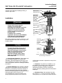
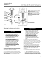
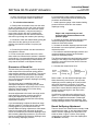
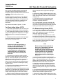
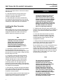
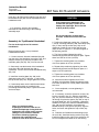
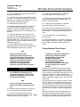
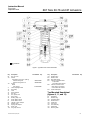
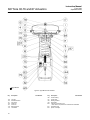
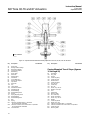
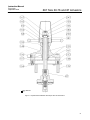
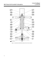
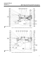
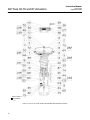
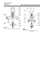
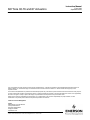
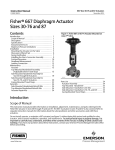
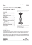
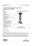
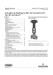
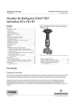
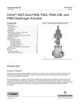
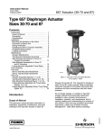
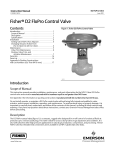
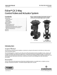
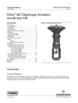
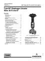
Instruction Manual
Form 1203
September 2004
667 Size 30-76 and 87 Actuators
Type 667 Diaphragm Actuator
Sizes 30-76 and 87
Contents
W1916-1*/IL
Figure 1. Type 667 or 667-4 Actuator Mounted
on easy-er Valve
Side-Mounted Handwheels Retrofit Kits . . . . .
Top-Mounted Handwheel Retrofit Kits . . . . . . .
Actuator Repair Kits . . . . . . . . . . . . . . . . . . . . . .
Parts List . . . . . . . . . . . . . . . . . . . . . . . . . . . . . . . . . .
Actuator Assembly . . . . . . . . . . . . . . . . . . . . . . .
Top-Mounted Handwheel . . . . . . . . . . . . . . . . .
Side-Mounted Handwheel (30-60) . . . . . . . . .
Side-Mounted Handwheel (70, 76, and 87) .
Casing Mounted Travel Stops . . . . . . . . . . . . .
19
19
19
19
19
21
23
23
24
D100310X012
Introduction . . . . . . . . . . . . . . . . . . . . . . . . . . . . . . . . . 2
Scope of Manual . . . . . . . . . . . . . . . . . . . . . . . . . . 2
Description . . . . . . . . . . . . . . . . . . . . . . . . . . . . . . . 2
Specifications . . . . . . . . . . . . . . . . . . . . . . . . . . . . 3
Maximum Pressure Limitations . . . . . . . . . . . . . 3
Installation . . . . . . . . . . . . . . . . . . . . . . . . . . . . . . . . . . 4
Mounting the Actuator on the Valve . . . . . . . . . . 5
Discussion of Bench Set . . . . . . . . . . . . . . . . . . . 6
Bench Set Spring Adjustment . . . . . . . . . . . . . . . 6
For Direct Acting Valves (PDTC) . . . . . . . . . . . 7
For Reverse Acting Valves (PDTO) . . . . . . . . 7
Installing the Stem Connector Assembly . . . . . 8
Deadband Measurement . . . . . . . . . . . . . . . . . . . 9
Loading Connection . . . . . . . . . . . . . . . . . . . . . . . 9
Maintenance . . . . . . . . . . . . . . . . . . . . . . . . . . . . . . . . 9
Actuator . . . . . . . . . . . . . . . . . . . . . . . . . . . . . . . . 10
Actuator Disassembly . . . . . . . . . . . . . . . . . . . 10
Actuator Assembly . . . . . . . . . . . . . . . . . . . . . . 11
Top-Mounted Handwheel Assembly
(Adjustable Down Travel Stop) . . . . . . . . . . 11
Disassembly for Top-Mounted Handwheel 12
Assembly for Top-Mounted Handwheel . . 13
Side-Mounted Handwheel Assembly for
Size 34 through 60 Actuators . . . . . . . . . . . . 14
Disassembly for Side-Mounted
Handwheel (34-60) . . . . . . . . . . . . . . . . . . . . 14
Assembly for Side-Mounted
Handwheel (34-60) . . . . . . . . . . . . . . . . . . . . 15
Side-Mounted Handwheel Assembly for
Size 70, 76, and 87 Actuators . . . . . . . . . . . 15
Disassembly for Side-Mounted
Handwheel (70, 76, and 87) . . . . . . . . . . . . . 15
Assembly for Side-Mounted Handwheel
Handwheel (70, 76, and 87) . . . . . . . . . . . . . 16
Casing-Mounted Travel Stops . . . . . . . . . . . . . 17
Parts Kits . . . . . . . . . . . . . . . . . . . . . . . . . . . . . . . . . . 19
www.Fisher.com
Instruction Manual
Form 1203
September 2004
667 Size 30-76 and 87 Actuators
Table 1. Specifications
ACTUATOR SIZE
SPECIFICATION (1)
Nominal Effective Area
Yoke Boss Diameter
Acceptable Valve Stem Diameter
Maximum Allowable Output Thrust(4)
Standard
Maximum Travel(2)
Top Loaded
Top-Loaded
Maximum Casing Pressure for
Actuator Sizing(4,6)
Maximum Excess Diaphragm
Pressure (4,5)
Maximum Diaphragm Casing
Pressure (4,6,7)
Approximate Weight
30
34
40
45
46
50
60
70(1)
76
87(1)
Sq cm
297
445
445
667
1006
677
1006
1419
1006
1419
Sq Inch
46
69
69
105
156
105
156
220
156
220
mm
54
54
71
71
71
90
90
90
90
125
Inch
2.125
2.125
2.8125
2.8125
2.8125
3.5625
3.5625
3.5625
3.5625
5
mm
9.5
9.5
12.7
12.7
12.7
19.1
19.1
19.1
19.1
25.4
Inch
0.375
0.375
0.5
0.5
0.5
0.75
0.75
0.75
0.75
1
N
10,230
10,230
12,010
25,131
33,582
25,131
30,246
39,142
30,246
39,142
LB
2300
2300
2700
5650
7550
5650
6800
8800
6800
8800
mm
19
29
38
51
51
51
51
76(3)
51
76(3)
Inch
0.75
1.125
1.5
2
2
2
2
3(3)
2
3(3)
mm
---
19
---
19
---
---
29
---
29
76
Inch
---
0.75
---
0.75
---
---
1.125
---
1.125
3
Bar
3.8
4.8
4.8
4.5
3.5
4.5
3.5
3.4
3.4
3.4
Psig
55
70
70
65
55
65
55
50
50
50
Bar
3.9
1.4
1.4
0.7
0.7
0.7
0.7
0.7
0.7
0.7
Psig
55
20
20
10
10
10
10
10
10
10
Bar
7.6
6.2
6.2
5.2
4.5
5.2
4.5
4.1
4.1
4.1
Psig
110
90
90
75
65
75
65
60
60
60
Kg
15
22
23
41
55
43
55
115
86
118
Pounds
34
48
50
90
121
94
122
254
190
260
Material
Nitrile Elastomers
Temperature
Capabilities Silicone Elastomers
–40 to 82_C (–40 to 180_F)
–54 to 149_C (–65 to 300_F)
1. These values also apply to the Type 667-4 actuator construction.
2. Actuator travel may be less than the value listed after connected to the valve.
3. Maximum actuator travel for Type 667-4 is 102 mm (4 inches).
4. See also the Specification portion of the introduction section.
5. Additional pressure may be added when the actuator is at full travel. If the Maximum Excess Diaphragm Pressure is exceeded, damage to the diaphragm or diaphragm casing might
result. See the Maximum Pressure Limitation section.
6. Maximum diaphragm casing pressure must not be exceeded and must not produce a force on the actuator stem greater than the maximum allowable actuator output thrust or the
maximum allowable stem load. See the Maximum Pressure Limitation section.
7. This maximum casing pressure is not to be used for normal operating pressure. Its purpose is to allow for typical regulator supply settings and/or relief valve tolerances.
Introduction
Scope of Manual
This instruction manual provides information on
installation, adjustment, maintenance, and parts
ordering for the Type 667 actuator in sizes 30
through 76 and size 87. The Type 667-4 actuator in
sizes 70 and 87 is also covered. Refer to separate
instruction manuals for information about the valve
positioner and other accessories used with these
actuators.
No person may install, operate, or maintain a Type
667 actuator (see figure 1) without first D being fully
trained and qualified in valve, actuator, and
accessory installation, operation, and maintenance,
and D carefully reading and understanding the
contents of this manual. If you have any questions
about these instructions, contact your Fisher sales
office before proceeding.
2
Note
Fisher does not assume responsibility
for the selection, use, or maintenance
of any product. Responsibility for
proper selection, use, and
maintenance of any Fisher product
remains solely with the purchaser and
end-user.
Description
The Type 667 actuator (figure 1) and the Type 667-4
actuator are reverse-acting, spring-opposed
diaphragm actuators. They provide automatic
operation of control valves. The Type 667 actuator
provides 76 mm (3 inches) maximum actuator travel.
The Type 667-4 actuator provides 102 mm (4
inches) maximum actuator travel. Both actuators
position the valve plug in response to varying
pneumatic loading pressure on the diaphragm.
Figure 2 shows the operation of these actuators.
Instruction Manual
Form 1203
September 2004
667 Size 30-76 and 87 Actuators
Specifications
Refer to table 1 for Specifications of the Type 667
and 667-4 actuators. See the actuator nameplate for
specific information for your actuator.
SPRING PUSHES
STEM DOWN
AIR LIFTS
STEM UP
STEM
SEAL
STEM
WARNING
To avoid personal injury or damage to
equipment that may result in the
malfunction of the control valve or
loss of control of the process caused
by excessive pressure, do not exceed
the Maximum Pressures listed in table
1. Refer to the Maximum Pressure
Limitations section below.
A6759/IL
Figure 2. Schematic of Type 667 and 667-4 Actuators
A Type 667 or 667-4 actuator can be furnished with
either a top-mounted or a side-mounted handwheel
assembly. A top-mounted handwheel assembly is
normally used as an adjustable down travel stop. (A
down travel stop limits actuator travel in the down
direction [when the stem is traveling out of the
actuator]. Travel in the up direction is when the stem
is traveling into the actuator.) A side-mounted
handwheel assembly is normally used as an
auxiliary manual actuator. The side-mounted
handwheel can also be used as an adjustable up or
down travel stop. Casing-Mounted adjustable up or
down travel stops are also available on this actuator.
Note
If repeated or daily manual operation is
expected, the actuator should be
equipped with a side-mounted
handwheel rather than a
casing-mounted travel stop or
top-mounted handwheel. The
side-mounted handwheel is designed
for more frequent use as a manual
operator.
Maximum Pressure Limitations
The casing and diaphragm of Type 667 actuators
are pressure operated. This air pressure provides
energy to compress the spring, to stroke the
actuator, and to seat the valve. The following
explanations describe the maximum pressure limits
for an actuator. Refer to the nameplate or table 1 for
maximum values for your actuator.
D Maximum Casing Pressure for Actuator
Sizing: This is the maximum pressure that can be
applied at less than full travel of the actuator. If this
stroking pressure is exceeded before the upper
diaphragm plate contacts the travel stop, damage to
the stem or other parts might result.
D Maximum Excess Diaphragm Pressure:
Additional pressure may be added when the actuator
is at full travel. If the Maximum Excess Diaphragm
Pressure is exceeded, damage to the diaphragm or
diaphragm casing might result.
Because the actuator has traveled its specified
travel, and the diaphragm head is physically stopped
from movement, the energy from any additional air
pressure is transmitted to the diaphragm and
diaphragm casings. The amount of air pressure that
can be added once the actuator has traveled to the
stops is limited by the resultant adverse effects that
may occur. Exceeding this limiting factor could result
in leakage or casing fatigue due to the deformation
of the upper diaphragm casing.
D Maximum Diaphragm Casing Pressure: If the
Maximum Diaphragm Casing Pressure is exceeded,
3
Instruction Manual
Form 1203
September 2004
667 Size 30-76 and 87 Actuators
damage to the diaphragm, diaphragm casing, or
actuator might result.
VENT NPT FEMALE
CONNECTION (TOP LOADING)
DIAPHRAGM CASINGS
DIAPHRAGM AND
STEM SHOWN IN
DOWN POSITION
DIAPHRAGM
PLATE
Installation
NPT FEMALE
CONNECTION
WARNING
ACTUATOR SPRING
ACTUATOR STEM
Always wear protective gloves,
clothing, and eyewear when
performing any installation operations.
Check with your process or safety
engineer for any other hazards that
may be present from exposure to
process media.
If installing into an existing
application, also refer to the WARNING
at the beginning of the Maintenance
section in this instruction manual.
Key number locations are shown in figures 6, 7, and
8, unless otherwise noted. Also, refer to figure 3 for
location of parts.
CAUTION
To avoid parts damage, do not use an
operating pressure that exceeds the
Maximum Diaphragm Casing Pressure
(table 1) or produces a force on the
actuator stem greater than the
Maximum Allowable Output Thrust
(table 1) or the Maximum Allowable
Valve Stem Load.
D Valve/Actuator Assembly: If the actuator and
valve are shipped together as a control valve
assembly, it has been adjusted at the factory, and
may be installed in the pipeline. After installing the
valve in the pipeline, refer to the Loading Connection
procedures.
D Actuator Mounting: If the actuator is shipped
separately or the actuator has been removed from
the valve, it is necessary to mount the actuator on
the valve before placing the valve in the pipeline.
Refer to the following actuator mounting procedures
before placing the valve in service. It is
recommended that you perform the Bench Set
Spring Adjustment procedures in this section to
4
SPRING SEAT
SPRING ADJUSTOR
STEM CONNECTOR
YOKE
TRAVEL INDICATOR DISK
INDICATOR SCALE
W0364–1/IL
VALVE STEM
YOKE LOCK NUT
MATCH LINE
FOR
ACTUATOR
YOKE BOSS
DIAMETER
BONNET
TYPICAL VALVE
(REFER TO
VALVE MANUAL)
W6199–1/IL
Figure 3. Actuator-Mounting Components for
Size 30 through 70 Actuators
confirm that the actuator is adjusted correctly for the
valve travel.
D Positioner: If a positioner is installed, or is to
be installed on the actuator, refer to the positioner
instruction manual for installation. During the
adjustment procedures, it will be necessary to
provide a temporary loading pressure to the actuator
diaphragm.
D Handwheel Cap: If the handwheel cap (key
247, figures 9, 11, or 16) is not in place, install the
cap by pushing it on by hand until it snaps into place.
Instruction Manual
Form 1203
September 2004
667 Size 30-76 and 87 Actuators
NOTES:
1 THE LOWER PSIG LOADING PRESSURE (MARKED
ON NAMEPLATE) WHERE THE FIRST MOVEMENT OF
ACTUATOR STEM IS DETECTED.
2 MARK THIS POINT WITH TAPE OR A MARKER.
3 THE UPPER PSIG LOADING PRESSURE RETRACTS
ACTUATOR STEM.
4 MEASURE DISTANCE OF TRAVEL. IT SHOULD
EQUAL THE TRAVEL SPAN SHOWN ON THE TRAVEL
INDICATOR SCALE.
SPRING
ADJUSTER
ACTUATOR STEM
RATED VALVE
TRAVEL MEASURE
UPPER BENCH
SET LOADING
PRESSURE 3
LOWER BENCH
SET PRESSURE
MARK 4
VALVE STEM
4
1 LOWER BENCH SET
LOADING PRESSURE
MARK VALVE
STEM HERE 2
50A8379-C
B2429-1 / IL
Figure 4. Bench Set Adjustment
Mounting the Actuator on the Valve
CAUTION
The Type 667 actuator spring load
pushes the stem down out of the
actuator yoke (see figure 2), and it can
come in contact with the valve stem
during actuator mounting.
If the valve stem is allowed to remain
in the up position (towards the
actuator) during actuator mounting, it
can interfere with the actuator stem
during mounting. It is possible to
damage valve stem threads or bend
the valve stem. Be sure the valve stem
is pushed down (into the valve body),
away from the actuator while
mounting.
It may be necessary to apply a temporary loading
pressure to the actuator to move the actuator stem
away from the valve during installation.
If it is not possible to provide a temporary loading
pressure, be very careful when lowering the actuator
over the valve stem to prevent damage to valve
stem and threads.
WARNING
When moving the actuator stem with
loading pressure applied, exercise
caution to keep hands and tools out of
the actuator stem travel path. If the
loading pressure is accidently
disconnected, personal injury and
property damage may result if
something is caught between the
actuator stem and other control valve
parts.
1. Provide a vise or some other method of
supporting the valve and the weight of the actuator
during assembly. For direct or reverse acting valves,
push the valve stem down away from the actuator
while mounting the actuator.
2. Screw the stem locknuts all the way onto the
valve stem. With the concave side of the travel
indicator disk (key 34) facing the valve, install the
travel indicator disk on the valve stem. (Note: The
travel indicator disk is not used with size 87
actuators.)
3. Lift or hoist the actuator onto the valve bonnet:
a. For size 87 actuators: Slowly lower the
actuator down onto the valve while guiding the
valve stem into the opening in the end of the the
actuator stem (see figure 4). Once the actuator is
5
Instruction Manual
Form 1203
September 2004
667 Size 30-76 and 87 Actuators
in place, insert the cap screws and tighten the
hex nuts, securing the actuator to the bonnet.
b. For all other size actuators:
D Slowly lower the actuator down onto the valve.
As the yoke passes over the end of the valve stem,
place the yoke locknut over the valve stem. (Note:
On small size actuators, it may be necessary to
remove the indicator disk and re-install it while
lowering the actuator onto the valve because the
disk will not go through the actuator yoke opening).
D Continue to lower the actuator while guiding the
valve stem into the opening in the end of the
actuator stem until the actuator is in place (see
figure 4).
D Screw the yoke locknut onto the valve bonnet
and tighten the locknut.
4. Do not connect the actuator stem to the valve
stem at this time. Whenever the actuator is installed
on the valve, it is recommended that you perform the
Bench Set Spring Adjustment procedures below, to
verify that the actuator is still adjusted correctly.
Discussion of Bench Set
The bench set pressure range is used to adjust the
initial compression of the actuator spring with the
valve-actuator assembly “on the bench.” The correct
initial compression ensures that the valve-actuator
assembly will function properly when it is put into
service and the proper actuator diaphragm operating
pressure is applied.
The bench set range is established with the
assumption that there is no packing friction. When
attempting to adjust the spring in the field, it is very
difficult to ensure that there is no friction being
applied by “loose” packing.
Accurate adjustment to the bench set range can be
made during the actuator mounting process by
making the adjustment before the actuator is
connected to the valve (see the Bench Set Spring
Adjustment Procedure).
If you are attempting to adjust the bench set range
after the actuator is connected to the valve and the
packing tightened, you must take friction into
account. Make the spring adjustment so full actuator
travel occurs at the bench set range (a) plus the
friction force divided by the effective diaphragm area
with increasing diaphragm pressure or (b) minus the
friction force divided by the effective diaphragm area
with decreasing diaphragm pressure.
6
For an assembled valve-actuator assembly, the
valve friction may be determined by following the
procedure described below:
1. Install a pressure gauge in the actuator loading
pressure line that connects to the actuator
diaphragm casing.
Note
Steps 2 and 4 require that you read
and record the pressure shown on the
pressure gauge.
2. Increase the actuator diaphragm pressure and
read the diaphragm pressure as the actuator
reaches its mid-travel position.
3. Increase the actuator diaphragm pressure until
the actuator is at a travel position greater than its
mid-travel position.
4. Decrease the actuator diaphragm pressure and
read the diaphragm pressure as the actuator
reaches its mid-travel position.
The difference between the two diaphragm pressure
readings is the change in the diaphragm pressure
required to overcome the friction forces in the two
directions of travel.
5. Calculate the actual friction force:
Friction
Force, = 0.5
pounds
ǒ
Ǔ ǒ
Difference
in pressure
readings, psig
Effective
diaphragm area,
inches2
Ǔ
Refer to table 1 for the effective diaphragm area.
When determining valve friction, you can make
diaphragm pressure readings at a travel position
other than mid-travel if you desire. If you take
readings at zero or at the full travel position, take
extra care to ensure that the readings are taken
when the travel just begins or just stops at the
position selected.
It is difficult to rotate the spring adjustor (key 74,
figure 6, 7, and 8) when the full actuator loading
pressure is applied to the actuator. Release the
actuator loading pressure before adjusting. Then
re-apply loading pressure to check the adjustment.
Bench Set Spring Adjustment
The term “bench set” means that the actuator is not
connected to the valve, or any other loads. Ensure
that the actuator diaphragm is at the bottom of its
travel as shown in figure 4. (Note: Some spring
compression is required to move the diaphragm to
the bottom of its travel.)
Instruction Manual
Form 1203
September 2004
667 Size 30-76 and 87 Actuators
Also, provide a certified pressure gauge that will
accurately read the diaphragm pressure from 0
through the upper bench set pressure marked on the
nameplate. Apply loading pressure to the
diaphragm.
Stroke the actuator a few times to ensure that the
pressure gauge is working correctly, and that the
actuator is functioning properly. It is important to be
sure that the actuator assembly is not binding or
producing any friction on the actuator stem
movement.
Key numbers are shown in figures 6, 7, and 8.
For Direct-Acting Valves (PDTC)
1. If not already accomplished, push the valve stem
down away from the actuator to the closed position.
2. Set the diaphragm loading pressure to 0.3 bar (5
psig) over the upper bench set pressure. The upper
travel stop should be contacting the diaphragm
casing.
3. Slowly decrease the pressure towards the upper
bench set pressure while checking for the first
movement of the actuator stem.
Note
Before turning the spring adjuster on
size 70, 76, or 87 actuators, assemble
the stem connector around the
actuator stem and the anti-rotating lug
on the yoke. Mark the actuator stem as
a visual reference to verify that stem
rotation does not occur. Remove the
stem connector before rechecking the
bench set.
4. If movement occurs before or after the upper
pressure is reached, adjust the spring adjuster (see
figure 4). Thread the adjuster up or down on the
actuator stem until the actuator stem movement is
first detected at the upper bench set pressure.
(Note: You may need to lower the loading pressure
to reduce spring compression, allowing the spring
adjuster to turn.)
5. Be sure the spring adjuster is adjusted to meet
the requirements of step 4 above.
6. Apply the lower bench set loading pressure to the
diaphragm. This will extend the actuator stem toward
the valve. Mark the end of the actuator stem on a
nearby surface using tape or some other method.
7. Slowly increase the diaphragm pressure until the
upper bench set loading pressure is applied. Again,
the travel stop should be against the diaphragm
casing.
8. Measure the distance between the mark or tape
to the end of the actuator stem. This distance should
match the travel span shown on the travel indicator
scale (key 32).
9. If the span of travel is correct, bench set is
complete. Proceed to the Installing the Stem
Connector Assembly subsection.
10. If the travel span is not exact, remember the
free-length and load rate tolerances for the spring
may produce a slightly different span than specified.
Contact your Fisher sales office for assistance.
For Reverse-Acting Valves (PDTO)
1. If not already accomplished, push the valve stem
down away from the actuator to the open position.
Later, when installing the connector, pull up the
valve stem to the closed position.
2. Set the diaphragm loading pressure to a value
less than the lower bench set pressure (near zero).
The down travel stop should be contacting the yoke.
3. Slowly increase the pressure towards the lower
bench set pressure while checking for the first
movement of the actuator stem.
Note
Before turning the spring adjuster on
size 70, 76, or 87 actuators, assemble
the stem connector around the
actuator stem and the anti-rotating lug
on the yoke. Mark the actuator stem as
a visual reference to verify that stem
rotation does not occur. Remove the
stem connector before rechecking the
bench set.
4. If movement occurs before or after the lower
pressure is reached, adjust the spring adjuster (see
figure 4). Thread the adjuster up or down on the
actuator stem until the actuator stem movement is
first detected at the lower bench set pressure.
5. Apply the upper bench set loading pressure to
the diaphragm. This will retract the actuator stem
away from the valve. Mark the end of the actuator
stem on a nearby surface using tape or some other
method.
6. Slowly decrease the diaphragm pressure until the
lower bench set loading pressure is applied. Again,
the down-stops should be against the yoke.
7. Measure the distance between the mark or tape
to the end of the actuator stem. This distance should
7
Instruction Manual
Form 1203
September 2004
667 Size 30-76 and 87 Actuators
match the travel span shown on the travel indicator
scale (key 32).
8. If the span of travel is correct, bench set is
complete. Proceed to the Installing the Stem
Connector Assembly subsection.
9. If the travel span is not exact, remember the
free-length and load rate tolerances for the spring
may produce a slightly different span than specified.
Contact your Fisher sales office for assistance.
Installing the Stem Connector
Assembly
When installing the stem connector assembly (key
31), the actuator and valve stem threads should
engage the threads of the stem connector by a
distance equal to the diameter of the stem.
Note
Replacement stem connectors are an
assembly of two stem connector
halves, cap screws, and a spacer
between the connector halves.
Remove the spacer and discard it, if
present, before clamping the actuator
and valve stems together.
1. If necessary, push the valve stem down so that
the valve plug is touching the seat ring on
direct-acting valves. For reverse-acting valves, pull
the stem up to the closed position. Always start with
the valve plug on the seat.
2. If necessary, screw the valve stem locknuts
down, away from the connector location. For all
actuators except size 87, ensure that the travel
indicator disk (key 34) is on top of the locknuts.
3. Adjust the diaphragm pressure to the lower
bench set pressure. (Or, the upper bench set
pressure for reverse-acting valves.) This should be
the same pressure used in the bench set steps, and
it is marked on the nameplate.
4. Place the stem connector half with the threaded
holes, approximately half way between the actuator
and valve stems. Refer to figures 6, 7, and 8 to help
locate the connector position.
Be sure that the actuator and valve stem threads are
engaging the threads of the stem connector by a
distance equal to one diameter of the stem.
8
CAUTION
Incomplete engagement of either the
valve stem or actuator stem in the
stem connector can result in stripped
threads or improper operation. Be sure
that the length of each stem clamped
in the stem connector is equal to or
greater than one diameter of that stem.
Damage to threads on either stem or in
the stem connector can cause the
parts to be replaced prematurely.
5. Install the other half of the stem connector and
insert the cap screws and tighten them. If installing a
positioner, also attach the feedback bracket at the
same time.
6. Screw the valve stem locknuts up until the
indicator disk contacts the bottom of the stem
connector, or for size 87 actuators, tighten the
locknuts against the stem connector. Do not
overtighten the locknuts.
7. Slowly increase and then decrease pressure
several times, stroking the valve from the lower
bench set pressure to the upper pressure.
Be sure that the valve is in the closed position (up or
down, depending on valve action). Loosen the
screws on the travel scale, and align it with the travel
indicator disk. Stroke the valve full travel to ensure
that the travel matches the valve travel on the travel
indicator plate. If valve travel is not correct, repeat
the stem connector procedure.
Note
For push-down-to-close valves, the
valve plug seat is the limit for
downward travel and the actuator
up-stop is the limit for upward (away
from the valve) movement. For
push-down-to-open valves, the
actuator down-stop is the limit for
downward movement, and the valve
seat is the limit for upward (away from
the valve) movement. For Type 667
actuators, a down-stop (key 77, figure
6) is installed to limit actuator
diaphragm downward movement when
the actuator provides the limit.
Instruction Manual
667 Size 30-76 and 87 Actuators
4. Calculate the percent of deadband by:
OPENING
VALVE
UPPER
BENCH SET 15
PRESSURE
1.0
0.6
9
LOWER
BENCH SET
PRESSURE
RANGE OF
DEADBAND
CLOSING
VALVE
3
1
DIAPHRAGM PRESSURE, BAR
DIAPHRAGM PRESSURE, PSIG
Form 1203
September 2004
0.2
0
CLOSED
MID RANGE
OPEN
VALVE TRAVEL
NOTE:
1 DEADBAND IS CAUSED BY FRICTION.
A6588-1 / IL
Figure 5. Typical Reverse-Acting Valve Response
to Deadband
Deadband, psi
Deadband =
Deadband, psi
= nn %
Bench Set Span, psi
Loading Connection
Key number locations are shown in figures 6, 7, and
8, unless otherwise noted.
The loading pressure connections are made at the
factory if the valve, actuator, and positioner come as
a unit. Keep the length of tubing or piping as short as
possible to avoid transmission lag in the control
signal. If a volume booster, valve positioner or other
accessory is used, be sure that it is properly
connected to the actuator. Refer to the positioner
instruction manual or other manuals as necessary.
For actuators shipped separately or whenever the
actuator pressure connections are installed, use the
following steps:
1. Connect the loading pressure piping to the NPT
female connection in the side of the yoke (key 73).
Deadband Measurement
Deadband is caused by packing friction, unbalanced
forces, and other factors in the control valve
assembly. Deadband is the range a measured signal
can vary without initiating a response from the
actuator (see figure 5). Each actuator spring has a
fixed spring rate (force). You have verified that the
right spring was installed in the actuator by
completing the Bench Set Spring Adjustment steps.
Deadband is one factor that affects the control valve
assembly operation during automatic loop control.
The control loop tolerance for deadband varies
widely depending on the loop response. Some
common symptoms of the deadband being too wide
are no movement, a ‘‘jump” movement, or oscillating
movements of the actuator during automatic loop
control. The following steps are provided to
determine the span of deadband. The percent of
deadband is helpful in troubleshooting problems with
the process control loop.
1. Start at a pressure near the lower bench set
pressure, slowly increase pressure until the valve is
approximately at mid-travel. Note this pressure
reading.
2. Slowly decrease pressure until movement of the
valve stem is detected, and note this pressure.
3. The difference between these two pressures is
deadband, in psi.
2. For size 70 and 87 actuators, if necessary,
remove the 0.25 inch NPT bushing if a 0.5 inch NPT
female connection is needed to increase connection
size. The connection can be made with either piping
or tubing.
3. Cycle the actuator several times to be sure that
the valve stem travel is correct when the correct
pressure ranges are applied to the diaphragm.
4. If valve stem travel appears to be incorrect, refer
to the Bench Set Spring Adjustment procedures at
the beginning of this section. Do not place the valve
in service if it is not reacting correctly to diaphragm
loading pressure changes.
Maintenance
Actuator parts are subject to normal wear and must
be inspected regularly and replaced when
necessary. The frequency of inspection and
replacement depends on the severity of service
conditions.
WARNING
Avoid personal injury or property
damage from sudden release of
process pressure or uncontrolled
movement of parts. Before performing
any maintenance operations:
9
Instruction Manual
Form 1203
September 2004
667 Size 30-76 and 87 Actuators
D Always wear protective gloves,
clothing, and eyewear when
performing any maintenance
operations to avoid personal injury.
D Disconnect any operating lines
providing air pressure, electric power,
or a control signal to the actuator. Be
sure the actuator cannot suddenly
open or close the valve.
D Use bypass valves or completely
shut off the process to isolate the
valve from process pressure. Relieve
process pressure from both sides of
the valve. Drain the process media
from both sides of the valve.
D Vent the power actuator loading
pressure and relieve any actuator
spring pre-compression.
D Use lock-out procedures to be
sure that the above measures stay in
effect while you work on the
equipment.
D The valve packing box may
contain process fluids that are
pressurized, even when the valve has
been removed from the pipeline.
Process fluids may spray out under
pressure when removing the packing
hardware or packing rings, or when
loosening the packing box pipe plug.
D Check with your process or safety
engineer for any additional measures
that must be taken to protect against
process media.
The maintenance instructions are divided into
several sections: Actuator, Top-Mounted Handwheel
Assembly (Adjustable Down Travel Stop),
Side-Mounted Handwheel Assembly for Size 34
through 60 Actuators (Manual Actuator),
Side-Mounted Handwheel Assembly for Size 70, 76
and 87 Actuators (Manual Actuator), and
Casing-Mounted Travel Stops.
Actuator
This procedure describes how the actuator can be
completely disassembled and assembled. When
inspection or repairs are required, disassemble only
those parts necessary to accomplish the job; then,
start the assembly at the appropriate step.
10
Key numbers are shown in figures 6, 7, or 8, unless
otherwise noted. Figure 6 shows the size 30 through
60 actuators, figure 7 shows the size 70 actuator,
and figure 8 shows the size 87 actuator.
Actuator Disassembly
Isolate the control valve from the line pressure,
release pressure from both sides of the valve body,
and drain the process media from both sides of the
valve. Also shut off all pressure lines to the power
actuator, release all pressure from the actuator. Use
lock-out procedures to be sure that the above
measures stay in effect while you work on the
equipment.
1. Remove the tubing or piping from the connection
in the top of the yoke (key 73). For a top-loaded
construction, also remove the piping or tubing from
the connection in the upper diaphragm casing
(key 1).
2. Turn the spring adjuster (key 74)
counterclockwise (toward the valve body) until all
spring compression is relieved.
WARNING
To avoid personal injury due to the
sudden uncontrolled movement of
parts, do not loosen the stem
connector cap screws when the stem
connector has spring force applied to
it.
3. If necessary, remove the actuator from the valve
body by separating the stem connector (key 31).
Loosen the stem locknuts for the size 87 actuator,
and remove the stem connector nuts. For all other
sizes, separate the stem connector by loosening the
stem locknuts (keys 69 and 75) and unscrewing the
two stem connector cap screws.
4. Unscrew the spring adjuster (key 74) from the
actuator stem (key 144). Also lift the spring seat and
spring (key 19 and 18) out of the yoke.
5. Remove the diaphragm casing cap screws and
nuts (keys 13 and 14), and lift off the upper
diaphragm casing (key 1).
6. Remove the following connected parts: the
diaphragm (key 3), upper diaphragm plate (key 4),
spacer (key 2), cap screw (key 12), lower diaphragm
plate (key 71), and actuator stem (key 144). Be
careful when pulling the threads of the actuator stem
through the seal bushing (key 7) to avoid damaging
the O-rings (key 8).
Instruction Manual
Form 1203
September 2004
667 Size 30-76 and 87 Actuators
7. Remove the cap screw (key 12) to separate the
parts of this assembly.
8. To remove the seal bushing, remove the snap
ring (key 72), and lift out the bushing. Inspect, and if
necessary, replace O-rings (8 and 9).
9. Remove cap screws (key 30), and take off the
lower diaphragm casing (key 64) and the gasket
(key 70, size 30 through 60 and 76) or O-ring (key
70, size 70 or 87). If necessary, the down travel
stops (key 77) can be removed.
Actuator Assembly
1. Coat the O-rings (key 70, sizes 70 and 87) with
lubricant (key 237 or equivalent). Or, coat the gasket
with sealant (key 237 or equivalent). Place a new
gasket or O-ring (key 70) on the yoke (key 73).
Position the lower diaphragm casing (key 64) on the
yoke, align the holes, and insert and tighten the cap
screws (key 30). If down travel stops (key 77) were
removed, insert and tighten them.
2. Coat the O-rings (keys 8 and 9) with lubricant
(key 237 or equivalent) and place the O-rings in the
seal bushing (key 7).
3. Fill the seal bushing with lubricant (key 237 or
equivalent), slide the bushing into the yoke (key 73),
and install the snap ring (key 72).
4. Assemble the actuator stem (key 144), lower
diaphragm plate (key 71), diaphragm (key 3), upper
diaphragm plate (key 4), and the travel stop cap
screw and spacer (keys 12 and 2). Coat the cap
screw threads with Lubriplate Mag-1 or equivalent
(key 237). Tighten the cap screw (key 12) to 41 NSm
(30 lbfSft) torque for size 30 actuators, 68 NSm (50
lbfSft) torque for size 34 and 40 actuators, or 183
NSm (135 lbfSft) torque for size 45 to 76 and 87
actuators. Place this assembly in the actuator. Take
care when pushing the actuator stem through the
seal bushing so that the threads do not damage the
O-rings.
Note
When you replace actuator
diaphragms in the field, take care to
ensure the diaphragm casing bolts are
tightened to the proper load to prevent
leakage, but not crush the material.
Perform the following tightening
sequence with a manual torque
wrench for size 30-76 and 87 actuators.
CAUTION
Over-tightening the diaphragm cap
screws and nuts (keys 13 and 14) can
damage the diaphragm. Do not exceed
27 NSm (20 lbfSft) torque.
Note
Do not use lubricant on these bolts
and nuts. Fasteners must be clean and
dry.
5. Install the upper diaphragm casing (key 1), and
install the cap screws and nuts (keys 13 and 14).
Tighten the diaphragm cap screws and nuts in the
following manner.
6. The first four bolts tightened should be
diametrically opposed and 90 degrees apart. Tighten
these four bolts to 13 NSm (10 lbfSft).
7. Tighten the remaining bolts in a clockwise,
criss-cross pattern to 13 NSm (10 lbfSft).
8. Repeat this procedure by tightening four bolts,
diametrically opposed and 90 degrees apart, to a
torque of 27 NSm (20 lbfSft).
9. Tighten the remaining bolts in a clockwise,
criss-cross pattern to 27 NSm (20 lbfSft).
10. After the last bolt is tightened to 27 NSm
(20 lbfSft), all of the bolts should be tightened again
to 27 NSm (20 lbfSft) in a circular pattern around the
bolt circle.
11. Once completed, no more tightening is
recommended.
12. Install the actuator spring (key 18) and spring
seat (key 19). Apply lubricant (key 239 or equivalent)
to the threads of the actuator stem and to the
surface of the spring adjuster (key 74) that contacts
the spring seat. Thread the spring adjuster onto the
actuator stem.
13. Mount the actuator onto the valve in accordance
with the procedures in the Installation section.
Top-Mounted Handwheel Assembly
(Adjustable Down Travel Stop)
Actuator key numbers are shown in figures 6, 7, and
8. And, top-mounted handwheels are shown in
figures 9, 11, and 12.
11
Instruction Manual
667 Size 30-76 and 87 Actuators
Note
If repeated or daily manual operation is
expected, the actuator should be
equipped with a side-mounted
handwheel rather than a
casing-mounted travel stop or
top-mounted handwheel. The
side-mounted handwheel is designed
for more frequent use as a manual
operator.
A top-mounted handwheel assembly (figures 9, 11,
and 12) is usually used as an adjustable down travel
stop to limit full extension of the actuator stem.
Turning the handwheel counterclockwise pulls the
extension rod (key 150, figures 9, 11, and 12) up,
retracting the actuator stem.
Instructions are given below for complete
disassembly and assembly. Perform the
disassembly only as far as necessary to accomplish
the required maintenance; then, begin the assembly
at the appropriate step.
Disassembly for Top-Mounted
Handwheel
1. Bypass the control valve, reduce loading
pressure to atmospheric, and remove the tubing or
piping from the connection in the top of the yoke
(key 73, figures 6, 7, and 8).
Form 1203
September 2004
D Lubricate and re-install the handwheel screw
into handwheel body (key 148). Lubricate and
replace the races, bearing, and retainer (keys 181,
180, and 182). Replace the castle nut (key 166),
tighten it, and insert the cotter pin (key 167).
Replace the handwheel cap (key 247).
5. For size 30 through 60 and 76 actuator
handwheels (figures 9 and 11):
D Remove the cap screws (key 161). Make sure
that the guide plate can turn between the handwheel
body and the mounting plate (keys 157, 148 and
158).
D Remove the cap (key 247) and cotter pin (key
167). Remove the castle nut (key 166) and, if
necessary, unscrew the extension rod (key 150).
Remove the rod, the handwheel body (key 148), and
the attached parts.
D Remove the hex nuts and cap screws (keys 14
and 13, figures 6, 7, and 8) from the diaphragm
casings. Lift off the upper diaphragm casing (key 1)
and the mounting plate (key 158).
D Turn the handwheel (key 58) to remove the
handwheel screw (key 160) from the handwheel
body (key 148). Remove the retaining ring (key 60) if
the handwheel (key 58) must be separated from the
handwheel screw.
2. Turn the handwheel (key 58) clockwise so that
the handwheel assembly is not causing any spring
compression.
D If necessary, perform other actuator
maintenance before returning to the following
assembly steps.
3. Turn the actuator spring adjuster (key 74) to
relieve all the compression from the spring (key 18).
6. For size 70 and 87 actuator handwheels
(figure 12):
4. If servicing just the thrust bearing, races, and
handwheel screw (keys 180, 181, and 160), use the
following steps:
D Remove the cap (key 247). Take out the cotter
pin (key 167) and remove the castle nut, the bearing
retainer, and thrust bearing (keys 166, 182, 181, and
180). It is not necessary to remove the extension rod
(key 150) at this time.
D Remove the cap and take out the cotter pin.
Remove the castle nut, bearing retainer, thrust
bearing, and races (keys 247, 167, 166, 180, and
181).
D Use the handwheel to remove the handwheel
screw (key 160) from the handwheel body (key 148).
D If necessary, remove the extension rod (key
150) at this time. Most maintenance procedures do
not require the rod to be removed.
D Clean and inspect all parts or replace parts as
necessary. Upon re-assembly, lubricate handwheel
threads, bearings, and races with Never-Seez Nickel
Special (key 239) or equivalent.
12
D Remove the hex nuts and cap screws (keys 14
and 13, figures 6, 7, and 8) from the diaphragm
casings. Lift off the upper diaphragm casing (key 1),
handwheel body (key 148) and attached parts.
D If travel stops (key 152) are used, note and
record their position relative to the cap screws (key
154) for use in assembly. Remove the travel stops
and cap screws, and remove either the mounting
plate (key 158, figure 12) or the handwheel body
(key 148, figure 12) and attached parts.
D Turn the handwheel (key 58) to remove the
handwheel screw (key 160) from the handwheel
Instruction Manual
Form 1203
September 2004
667 Size 30-76 and 87 Actuators
body (key 148). Remove the retaining ring (key 60) if
the handwheel (key 58) must be separated from the
handwheel screw.
D If necessary, perform other actuator
maintenance before returning to the following
assembly steps.
CAUTION
Over-tightening the diaphragm cap
screws and nuts (keys 13 and 14) can
damage the diaphragm. Do not exceed
27 NSm (20 lbfSft) torque.
Note
Do not use lubricant on these bolts
and nuts. Fasteners must be clean and
dry.
Assembly for Top-Mounted Handwheel
For size 30 through 60 and 76 actuator
handwheels:
Refer to figures 9 and 11 for top-mounted
handwheel assemblies.
1. If it was removed, slide the handwheel (key 58)
onto the end of the handwheel screw (key 160), and
snap the retaining ring (key 60) into place. Also,
install the guide post (key 150) if it was removed.
2. Generously coat the threads of the handwheel
screw (key 160) with lubricant (key 239 or
equivalent). Turn the screw into the handwheel body
(key 148).
3. Install the mounting plate (key 158) to the
diaphragm casing (key 1, figures 6, 7, and 8) with
the cap screws (key 154). Finger tighten the screws.
4. If travel stops were used, install the travel stops
to their original positions as recorded in the
proceeding Disassembly steps. Tighten the screws
and travel stops.
Note
When you replace actuator
diaphragms in the field, take care to
ensure the diaphragm casing bolts are
tightened to the proper load to prevent
leakage, but not crush the material.
Perform the following tightening
sequence with a manual torque
wrench for size 30-76 and 87 actuators.
5. Position the diaphragm casing (key 1, figures 6,
7, and 8), mounting plate (key 158), travel stops (key
152), if used, and cap screws (key 154) on the
diaphragm. Install the cap screws and hex nuts
(keys 13 and 14, figures 6, 7, and 8) and tighten in
the following manner.
6. The first four bolts tightened should be
diametrically opposed and 90 degrees apart. Tighten
these four bolts to 13 NSm (10 lbfSft).
7. Tighten the remaining bolts in a clockwise,
criss-cross pattern to 13 NSm (10 lbfSft).
8. Repeat this procedure by tightening four bolts,
diametrically opposed and 90 degrees apart, to a
torque of 27 NSm (20 lbfSft).
9. Tighten the remaining bolts in a clockwise,
criss-cross pattern to 27 NSm (20 lbfSft).
10. After the last bolt is tightened to 27 NSm
(20 lbfSft), all of the bolts should be tightened again
to 27 NSm (20 lbfSft) in a circular pattern around the
bolt circle.
11. Once completed, no more tightening is
recommended.
12. If necessary, screw the extension rod (key 150
into the connector (key 27). Slide the guide plate
(key 157) onto the extension rod (key 150). For size
45 through 76, place the spacer (key 253) on top of
the guide plate (key 157). If necessary, replace the
extension rod (key 150). Slide the handwheel body
(key 148) over the extension rod, position the
handwheel body on the spacer (key 253), align the
holes, and insert and tighten the cap screws (key
161).
13. Lubricate and install the thrust bearings (keys
181 and 180), install the bearing retainer (key 182),
install the castle nut (key 166) on the extension rod.
Do not overtighten the castle nut on the bearing.
13
Instruction Manual
667 Size 30-76 and 87 Actuators
Install the cotter pin (key 167). Replace the cap (key
247).
14. Refer to the Assembly portion of the Actuator
maintenance section.
For size 70 and 87 actuators handwheels (figure
12):
Refer to figure 12 for top-mounted handwheel
assemblies.
1. If removed, slide the handwheel (key 58) onto the
end of the handwheel screw (key 160), and snap the
retaining ring (key 60) into place.
2. Generously coat the threads of the handwheel
screw (key 160) with lubricant (key 239 or
equivalent). Turn the screw into the handwheel body
(key 148).
3. If necessary, install the extension rod (key 150)
into the connector (key 27) and tighten it. Position
the handwheel body (key 148) on the diaphragm
casing (key 1, figures 6, 7, and 8), and align the
holes. Insert the cap screws (key 154). Finger
tighten the screws.
4. If travel stops were used, return the travel stops
to their original positions as recorded in the
proceeding Disassembly steps. Tighten the screws
and travel stops.
Note
When you replace actuator
diaphragms in the field, take care to
ensure the diaphragm casing bolts are
tightened to the proper load to prevent
leakage, but not crush the material.
Perform the following tightening
sequence with a manual torque
wrench for size 30-76 and 87 actuators.
CAUTION
Over-tightening the diaphragm cap
screws and nuts (keys 13 and 14) can
damage the diaphragm. Do not exceed
27 NSm (20 lbfSft) torque.
Note
Do not use lubricant on these bolts
and nuts. Fasteners must be clean and
dry.
14
Form 1203
September 2004
5. Slide the extension rod (key 150) into the
handwheel screw (key 160), and position the
diaphragm casing (key 1, figures 6, 7, and 8) with
the attached parts on the diaphragm. Install the cap
screws and hex nuts (keys 13 and 14, figures 6, 7,
and 8) and tighten in the following manner.
6. The first four bolts tightened should be
diametrically opposed and 90 degrees apart. Tighten
these four bolts to 13 NSm (10 lbfSft).
7. Tighten the remaining bolts in a clockwise,
criss-cross pattern to 13 NSm (10 lbfSft).
8. Repeat this procedure by tightening four bolts,
diametrically opposed and 90 degrees apart, to a
torque of 27 NSm (20 lbfSft).
9. Tighten the remaining bolts in a clockwise,
criss-cross pattern to 27 NSm (20 lbfSft).
10. After the last bolt is tightened to 27 NSm
(20 lbfSft), all of the bolts should be tightened again
to 27 NSm (20 lbfSft) in a circular pattern around the
bolt circle.
11. Once completed, no more tightening is
recommended.
12. Lubricate and install the thrust bearings (keys
180 and 181), install the bearing retainer (key 182),
install the castle nut (keys 166) on the extension rod.
Do not overtighten the castle nut on the bearing.
Install the cotter pin (key 167). Replace the cap (key
247).
13. Refer to the Assembly portion of the Actuator
maintenance section.
Side-Mounted Handwheel Assembly for
Size 34 through 60 Actuators
A side-mounted handwheel assembly (figures 13
and 14) is usually used as a manual actuator. This
design is frequently used to drive the valve open or
closed under loading conditions. Turning the
handwheel clockwise past the neutral position
always closes a push-down-to-close valve. A pair of
levers (key 146, figure 13) on a handwheel assembly
close the valve by moving the valve stem.
Instructions are given below for disassembly and
assembly. Perform the disassembly only as far as
necessary to accomplish the required maintenance;
then begin the assembly at the appropriate step.
Disassembly for Side-Mounted
Handwheel (34-60)
1. If desired, the handwheel assembly can be
removed from the actuator yoke. To do this, remove
Instruction Manual
Form 1203
September 2004
the nuts (keys 147 and 170) from the U-bolts (keys
166 and 143) that hold the assembly to the yoke.
2. Remove the retaining ring (key 154), and drive
out the lever pivot pin (key 153).
3. Two screws (key 156) hold the right- and
left-hand levers (key 146) together. Remove the
screw from the top of the levers so that the levers
will drop down out of the assembly. Disassemble
further, if necessary, by removing the other screw.
4. Remove the screw (key 161) and pointer
mounting bolt (key 159, not shown) located behind
the pointer (key 160).
5. Remove the nut (key 54), lockwasher (key 150),
and washer (key 149), and take off the handwheel
(key 51). Be careful not to lose the small ball (key
55) and spring (key 56).
6. Unscrew the bearing retainer (key 136) after
loosening the locking set screw (key 168, not
shown).
7. Pull the screw assembly (key 145) out of the
handwheel body. The operating nut (key 132) will
come out with the screw. Also, remove the bushing
(key 151) on sizes 34 and 40.
8. If required, remove the bearings (key 152), one
from the bearing retainer and the other from the
handwheel body.
Assembly for Side-Mounted Handwheel
(Sizes 34-60)
1. Pack the bearings (key 152) with lubricant (key
239 or equivalent). Insert one bearing and the
bushing (key 151) in the handwheel body (key 142)
as shown in figure 13 or 14. The bushing is not used
in a handwheel assembly for size 45 through 60
actuators.
2. Coat the screw threads with lubricant (key 239) or
equivalent, and thread the operating nut onto the
screw. Slide the second bearing (key 152) onto the
screw, and insert the end of the screw into either the
bushing (key 151) as shown in figure 13 or 14 or into
the bearing.
3. Thread the bearing retainer (key 136) into the
body (key 142). Completely tighten the bearing
retainer, and then loosen it one-quarter turn. Tighten
the set screw (key 168, not shown) to hold the
bearing retainer in place.
4. Coat the groove in the handwheel body (key 142)
with lubricant (key 237 or equivalent). Insert the
spring (key 56) and ball (key 55) into the handwheel
(key 51). Holding the ball and spring in the
handwheel, put the handwheel (key 51), the washer
667 Size 30-76 and 87 Actuators
(key 149), the lockwasher (key 150), and the hex nut
(key 54) on the end of the screw (key 145). Tighten
the hex nut.
5. Position the pointer mounting bolt (key 159, not
shown) and the pointer (key 160) as shown in figure
13 or 14. Insert and tighten the screw (key 161).
6. Assemble the two levers (key 146) with the cap
screws (key 156) for handwheel assemblies for size
45, 50, and 60 actuators or with the machine bolts
(key 156) for handwheel assemblies on size 34 and
40 actuators.
7. If the handwheel assembly was removed from the
yoke, remount the handjack assembly to the yoke
using the dowel pins for alignment. Position the
U-bolts (keys 166 and 143) on the yoke, and
hand-tighten the hex nuts (keys 170 and 147) to hold
the handwheel assembly in position. Cap screws
(key 163) should be tight against the yoke legs to
provide stability. Tighten nuts (key 144). Finish
tightening the U-bolt nuts to 163 NSm [120 lbfSft] (key
170) and 41 NSm [30 lbfSft] (key 147). Be sure the
handwheel assembly remains flat against the
mounting pad and perpendicular to the yoke.
8. Position the levers (key 146) as shown in figure
13 or 14. Insert the lever pivot pin (key 153), and
snap the retaining ring (key 154) onto the lever pivot
pin.
Side-Mounted Handwheel Assembly for
Size 70, 76, and 87 Actuators
A side-mounted handwheel assembly (figure 15) is
usually used as a manual actuator. Turning the
handwheel clockwise past the neutral position
always closes the valve body. A sleeve (key 123,
figure 15) on a handwheel assembly for a size 70,
76 or 87 actuator opens the valve body by moving
the valve stem.
Instructions are given below for complete
disassembly and assembly. Perform the
disassembly only as far as necessary to accomplish
the required maintenance; and then begin the
assembly at the appropriate step.
Disassembly for Side-Mounted
Handwheel (Sizes 70, 76, and 87)
1. Bypass the control valve. Reduce the loading
pressure to atmospheric. Disconnect the loading
pressure tubing or piping at the yoke.
2. Remove the cover band (key 87), and relieve
spring compression by turning the spring adjuster
(key 74) counterclockwise.
3. Remove the cap screws and nuts (keys 13 and
14) and lift off the upper diaphragm casing (key 1).
15
Instruction Manual
667 Size 30-76 and 87 Actuators
Form 1203
September 2004
4. Remove the travel stop screw (key 12) and
spacer (key 2), and take off the diaphragm plate (key
4), the diaphragm (key 3), and the lower diaphragm
plate (key 71).
3. Coat the worm shaft (key 51) threads with
lubricant (key 239 or equivalent), and slide the shaft
into the yoke so that the end of the shaft fits snugly
into the back bearing retainer.
5. Unscrew the cap screws (key 90) and remove the
following connected parts: the lower diaphragm
casing (key 64), the O-ring (key 70), spring case
adaptor (key 89), the seal bushing, O-rings, and
snap ring (keys 7, 8, 9, and 72).
4. Insert the bearing in the front bearing retainer
(key 49), and thread the retainer and ball bearing
into the yoke. Align the slot in the retainer with the
hole in the yoke, insert the set screw (key 52), and
tighten it.
6. Remove the snap ring (key 72), and slide the seal
bushing and O-rings (keys 7, 8, and 9) out of the
spring case adaptor (key 89).
5. Put the spring and ball (keys 141 and 142) in the
handwheel (key 58). Slide the handwheel onto the
worm shaft (key 51). Thread the hex nut (key 127)
onto the worm shaft.
7. Take out the actuator spring (key 18).
8. Remove the stem connector (key 31) and stem
connector cap screws.
9. Pull the actuator stem (key 144) up and out of the
yoke. The spring seat (key 19), spring adjuster (key
74), thrust bearing (key 128), and the pinned
adjusting screw (key 131) will come out with the
actuator stem.
10. Turn the handwheel so that the lower sleeve
(key 123) extends out of the bottom of the yoke. DO
NOT move the neutral indicator scale (key 125).
11. Loosen two set screws (key 121), and unscrew
the bearing retainer flange (key 45). Take out the
worm gear and two thrust bearings (key 132), one
on each side of the gear.
12. The worm shaft (key 51) and associated parts
can be disassembled, if desired, by first removing
the handwheel nut (key 127) and the handwheel
(key 58). Do not lose the small ball (key 141) and
spring (key 142).
13. Loosen the set screw (key 52) for each worm
shaft retainer (keys 48 and 49). Unscrew the two
worm retainers (keys 48 and 49). The ball bearings
(key 50) will come out with the retainers.
Assembly for Side-Mounted Handwheel
(Sizes 70, 76, and 87)
1. The front and back worm retainers (keys 48 and
49) each have a slot in their threads for a set screw
(key 52). Pack the ball bearings (key 50) with
lubricant (key 239) or equivalent, and insert one ball
bearing in the back worm retainer (key 49) as shown
in figure 15.
2. Thread the back bearing retainer and ball bearing
(keys 49 and 50) into the yoke. Align the slot in the
bearing retainer with the set screw hole in the yoke,
insert the set screw (key 52), and tighten it.
16
6. Pack the two needle bearings (key 132) and coat
the worm gear (key 44) threads with lubricant (key
239) or equivalent. Insert the key (key 122), the
bearings, and the worm gear in the yoke (key 73) as
shown in figure 15.
7. Slots are cut in the threads of the bearing retainer
flange (key 45). Thread the flange into the yoke so
that the slots and the holes for the set screws (key
121) align. Insert the screws, and tighten them.
8. The lower sleeve (key 123) has a milled groove in
one end. Coat the sleeve threads with lubricant (key
239 or equivalent), slide the end of the lower sleeve
with the groove into the bearing retainer flange, turn
the handwheel, and feed the sleeve through the
worm gear so that the slot in the lower sleeve
engages the key (key 122) in the yoke. Continue
turning the handwheel until the lower sleeve
protrudes 81 mm (3.19 inches) below the surface of
the yoke. The bottom of the lower sleeve should be
even with the bottom of the extension on the neutral
indicator.
9. Pack the thrust bearing (key 128) with lubricant
(key 239) or equivalent. Slide the actuator stem (key
144) and the attached adjusting screw (key 131), pin
(key 130), thrust bearing (key 128), spring seat (key
19), and spring adjuster (key 74) into the yoke. The
lower end of the stem slides through the lower
sleeve (key 123) and the lower sleeve slides into the
adjusting screw (key 131), as shown in figure 15.
10. Position the actuator stem (key 144) against the
valve stem. Clamp both stems between the two
halves of the stem connector (key 31), and be sure
the threads are engaged properly on both stems.
The stem connector should not be closer than 3.2
mm (0.125 inches) to the lower sleeve when the
actuator stem is in the retracted position. This
adjustment will provide approximately 3.2 mm (0.125
inches) of free travel of the lower sleeve in either
direction for manual operation. Fasten the halves
together with the cap screws.
Instruction Manual
Form 1203
September 2004
667 Size 30-76 and 87 Actuators
11. Put the actuator spring (key 18) in the yoke on
the spring seat (key 19).
20. Tighten the remaining bolts in a clockwise,
criss-cross pattern to 13 NSm (10 lbfSft).
12. Coat the O-rings (keys 8 and 9) with lubricant
(key 237) or equivalent, and insert them in the seal
bushing (key 7). Slide the seal bushing and O-rings
into the spring case adaptor (key 89).
21. Repeat this procedure by tightening four bolts,
diametrically opposed and 90 degrees apart, to a
torque of 27 NSm (20 lbfSft).
13. Install the snap ring (key 72).
22. Tighten the remaining bolts in a clockwise,
criss-cross pattern to 27 NSm (20 lbfSft).
14. Slide the seal bushing and O-rings (keys 7, 8,
and 9) over the actuator stem (key 144), and
position the spring case adaptor (key 89), lower
diaphragm casing (key 64), and O-ring (key 70) on
the yoke.
15. Insert and tighten the cap screws (key 90).
16. Slide the lower diaphragm plate (key 71), the
diaphragm (key 3) with the patterned side up, the
diaphragm plate (key 4), the spacer (key 2), and the
cap screw (key 12) on the actuator stem (key 144).
Tighten the cap screw.
17. Put the diaphragm casing (key 1) on the
diaphragm. Align the holes in the diaphragm (key 3)
and the diaphragm casings (keys 1 and 64).
Note
When you replace actuator
diaphragms in the field, take care to
ensure the diaphragm casing bolts are
tightened to the proper load to prevent
leakage, but not crush the material.
Perform the following tightening
sequence with a manual torque
wrench for size 30-76 and 87 actuators.
CAUTION
Over-tightening the diaphragm cap
screws and nuts (keys 13 and 14) can
damage the diaphragm. Do not exceed
27 NSm (20 lbfSft) torque.
Note
Do not use lubricant on these bolts
and nuts. Fasteners must be clean and
dry.
18. Install the cap screws and hex nuts (keys 13
and 14) and tighten in the following manner.
19. The first four bolts tightened should be
diametrically opposed and 90 degrees apart. Tighten
these four bolts to 13 NSm (10 lbfSft).
23. After the last bolt is tightened to 27 NSm (20
lbfSft), all of the bolts should be tightened again to 27
NSm (20 lbfSft) in a circular pattern around the bolt
circle.
24. Once completed, no more tightening is
recommended.
25. Return the actuator to service after completing
the Loading Connection procedure in the Installation
section and the procedures in the Adjustments
section.
Casing-Mounted Travel Stops
Note
If repeated or daily manual operation is
expected, the actuator should be
equipped with a side-mounted
handwheel rather than a
casing-mounted travel stop or
top-mounted handwheel. The
side-mounted handwheel is designed
for more frequent use as manual
operator.
Casing-mounted adjustable travel stops (shown in
figures 16 through 20) are available to limit travel in
the down direction (extending the actuator stem) or
in the up direction (retracting the actuator stem). The
travel stop in figure 16 is a down travel stop, the
travel stop in figure 17 is an up and down travel stop,
and the travel stops in figures 18, 19, and 20 are up
travel stops.
Use the locknuts (key 151, figures 16 and 17), stem
(key 150, figure 18), handwheel (key 58, figure 19)
or cap screw (key 177, figure 20) to set the point at
which the travel stop limits travel. Be sure to tighten
the locknuts and replace the cap (key 149, figures
16 and 18; key 247, figure 17) after setting the travel
stop.
Instructions are given below for disassembly and
assembly. Perform the disassembly only as far as
necessary to accomplish the required maintenance;
then, begin the assembly at the appropriate step.
17
Instruction Manual
Form 1203
September 2004
667 Size 30-76 and 87 Actuators
Key numbers are shown in figures 16 through 20.
1. Remove the cap (key 149 or 247) if the travel
stop uses one. For down travel stops, loosen the
locknuts (key 151, figures 16 and 17) so that the
stop is not causing any spring compression.
2. Bypass the control valve, reduce loading
pressure to atmospheric, and remove the tubing or
piping from the connection on top of the yoke (key
73, figures 6, 7, and 8).
3. For down travel stops, turn the spring adjuster
(key 74, figures 6, 7, and 8) out of the yoke toward
the stem connector (key 31) to relieve all the
compression in the spring (key 18).
4. For style 11 travel stops (figure 17), unscrew
the cap screws (key 161), and make sure that the
guide plate (key 157) can turn between the
handwheel body (key 148) and the mounting plate
(key 158).
5. Use a wrench on the nuts (key 151) to unscrew
the extension rod (key 150). Remove the rod, the
handwheel body (key 148), and the attached parts.
6. Unscrew the hex nuts and cap screws (keys 14
and 13, figures 6, 7, and 8) from the diaphragm
casings. Lift off the upper diaphragm casing (key 1,
figures 6, 7, and 8) and, for the style 11 travel stop,
the mounting plate (key 158). For styles 10, 12 and
13, the travel stop assembly will be removed with the
casing.
7. Note and record the position of travel stops (key
152) relative to the cap screws (key 154) for use in
assembly. Unscrew the travel stops and cap screws,
and remove either the mounting plate (key 158) or
the handwheel body (key 148) and attached parts.
8. Separate the stem (key 150) and screw (key 160,
figure 17) from the handwheel body.
9. Before reassembling, lubricate parts indicated by
key 239 in figures 16 through 20. Use lubricant (key
239 or equivalent).
10. Reassemble parts in the reverse order of
removal.
11. When replacing the cap screws (key 154) and, if
used, the travel stops (key 152), be sure to return
them to their original position as recorded in step 6.
CAUTION
Over-tightening the diaphragm cap
screws and nuts (keys 13 and 14),
figures 6, 7, and 8 can damage the
18
diaphragm. Do not exceed 27 NSm (20
lbfSft) torque.
12. Install the cap screws and nuts (keys 13 and 14,
figures 6, 7, and 8) and finger tighten. Tighten the
diaphragm cap screws and nuts to 27 NSm (20 lbfSft)
torque in a crisscross pattern.
13. Return the spring adjuster (key 74, figure 6, 7,
and 8) to its original position. Re-adjust the travel
stop.
Parts Ordering
Each actuator has a serial number stamped on the
nameplate. Always mention this number when
corresponding with your Fisher sales office
regarding technical information or replacement parts.
Also, reference the complete 11-character part
number of each needed part as found in the
following Parts Kits and Parts List sections.
Note
Use only genuine Fisher replacement
parts. Components that are not
supplied by Fisher should not, under
any circumstances, be used in any
Fisher valve, because they will void
your warranty, might adversely affect
the performance of the valve, and
might jeopardize worker and
workplace safety.
Note
Fisher does not assume responsibility
for the selection, use, or maintenance
of any product. Responsibility for
proper selection, use, and
maintenance of any Fisher product
remains solely with the purchaser and
end-user.
Instruction Manual
Form 1203
September 2004
667 Size 30-76 and 87 Actuators
Parts Kits
Actuator Assembly
Side-Mounted Handwheels Retrofit Kits
Key Description
Part Number
Retrofit Kit includes parts to add a Side-Mounted Handwheel.
Size 34 Push-Down-To-Close
30A8778X0E2
Size 34 Push-Down-To-Open
30A8778X0F2
Size 40 Push-Down-To-Close
30A8778X0G2
Size 40 Push-Down-To-Open
30A8778X0H2
Size 45 & 46 Push-Down-To-Close
40A8779X0A2
Size 45 & 46 Push-Down-To-Open
40A8779X0B2
Size 50 & 60 Push-Down-To-Close
40A8779X0C2
Size 50 & 60 Push-Down-To-Open
40A8779X0D2
Key
1
2
3*
Top-Mounted Handwheels Retrofit Kits
Retrofit Kit includes parts to add a Top-Mounted
Handwheel. Kit number 1 includes the handwheel
assembly only. Kit number 2 includes Kit number 1
and a new diaphragm case that is required to
mount the handwheel assembly.
Key
Description
Kit 1
Size 30
Sizes 34
Size 40
Sizes 45 & 50
Sizes 46, 60, AND 76
Sizes 70 & 87
30B3940X102
39B3940X022
39B3940X042
33B9224X012
33B9224X012
CV8060X0012
Kit 2
Size 30
Size 34
Size 40
Sizes 45 & 50
Sizes 46, 60, & 76
Sizes 70 & 87
30B3940X052
30B3940X062
30B3940X092
33B9224X022
33B9224X032
CV8060X0022
4
7*
Part Number
Actuator Repair Kits
8*
9*
Parts kit includes keys 8, 9, and 70.
O-ring material is nitrile, and gasket
material is composition.
Key
Description
Size 30
Sizes 34 & 40
Sizes 45 through 60
Sizes 70 & 87
Size 76
Part Number
R667X000302
R667X000402
R667X000502
R667X000702
R667X000762
Parts List
Note
Part numbers are shown for recommended spares
only. For part numbers not shown, contact your
Fisher sales office.
*Recommended spare parts
12
13
14
17
18
19
27
30
31
32
33
33
34
39
40
64
Description
Upper Diaphragm Casing
Travel Stop Spacer
Diaphragm
Molded Nitrile/Nylon
Size 30
Sizes 34 & 40
Sizes 45 & 50
Sizes 46, 60 & 76
Sizes 70 & 87
Molded Silicone/Polyester
Size 30
Sizes 34 & 40
Sizes 45 & 50
Sizes 46, 60 & 76
Sizes 70 & 87
Upper Diaphragm Plate
Bushing, Seal
Brass
Size 30
Sizes 34 & 40
Sizes 45 through 60
Sizes 70, 76 & 87
S41600 [416 stainless steel (SST)]
Size 30
Sizes 34 & 40
Sizes 45 through 60
PTFE w/25% Glass
Sizes 70, 76 & 87
O-Ring
Nitrile
Size 30
Sizes 34 & 40
Sizes 45 through 60
Sizes 70, 76 & 87
Fluoroelastomer
Size 30
Sizes 34 & 40
Sizes 45 through 60
Sizes 70, 76, & 87
O-Ring
Nitrile
Sizes 30 through 40
Sizes 45 through 87
Fluoroelastomer
Sizes 30 through 40
Sizes 45 through 87
Screw, Cap, hex hd
Hex hd Cap Screw
Hex Nut
Vent Assembly
Spring
Seat, Lower Spring
Extension Rod Conn
Hex hd Cap Screw
Stem Connector Assembly
Travel Indicator Scale
Screw, Self Tapping
Screw, Mach, Fill hd
Disk, Travel Indicator
Nameplate
Screw, Drive
Lower Diaphragm Casing
Part Number Qty
2E800002202
2E669902202
2E859602202
2E859802202
2N130902202
1
1
1
1
1
18B2713X012
18B2713X022
18B2713X032
18B2713X042
18B2713X052
1
1
1
1
1
1E791214012
1E682814012
1E845714012
1N1316X0052
1
1
1
1
1E7912X0012 1
1E6828X0012 1
1E8457X0012 1
1N1316X0042 1
1E5914X0052
1D237506992
1C5622X0022
1E736906992
2
2
2
2
1E5914X0062
1D237506382
1N285406382
1N1633X0012
2
2
2
2
1C415706992 1
1E845806992 1
1C4157X0032 1
1E8458X0022 1
19
Instruction Manual
667 Size 30-76 and 87 Actuators
50A8378-C
PARTIAL VIEW OF TOPĆLOADED TYPE 667
ACTUATOR SIZES 30 THROUGH 60
APPLY LUBRICANT OR SEALANT
50A8379-C/IL
Figure 6. Type 667 Actuator Sizes 30 through 60
20
Form 1203
September 2004
Instruction Manual
Form 1203
September 2004
667 Size 30-76 and 87 Actuators
APPLY LUBRICANT
50A8598-E / IL
Figure 7. Type 667 Size 70 and 76 Actuator
Key
69
70*
70*
71
72
73
74
75
76
77
78
79
81
82
83
89
90
102
Description
Nut, Hex, Jam
Gasket
Composition [up to 232°C (450°F)]
Sizes 30 through 40
Sizes 45 through 60 & 76
O-Ring
Nitrile
Size 70 & 87
Lower Diaphragm Plate
Ring, Snap
Yoke
Spring Adjuster
Nut, Hex
Nut, Speed, Twin
Stop, Travel
Bushing, Pipe, Hex
Screw, Mach, Flat Hd
Screw, Mach, Rd Hd
Indicator, Travel, Adaptor
Washer, Plain
Spring Case Adaptor
Screw, Cap
Plug, Pipe, Hex Hd
*Recommended spare parts
Part Number Qty
1E801204022 1
1E845404022 1
Key
144
227
228
237
239
1D269106992 1
254
Description
Actuator Stem
Washer, Plain
Stem Disk Spacer
Lubricant, Lubriplate MAG-1
or equivalent
not furnished with actuator
Lubricant, Anti-Size Lub-3
Never-Seez or equivalent
not furnished with actuator
Caution Nameplate
Part Number Qty
Top-Mounted Handwheel
(figures 9, 11, and 12)
58
60
148
150
152
154
156
157
158
Handwheel
Retainer Ring
Handwheel Body
Extension Rod
Travel Stop
Cap Screw
Vent Assembly
Guide Plate
Mounting Plate
21
Instruction Manual
Form 1203
September 2004
667 Size 30-76 and 87 Actuators
APPLY LUBRICANT
50A8600-E / IL
Figure 8. Type 667 Size 87 Actuator
Key
159
160
161
166
167
178
179
22
Description
Lock Nut
Handwheel Screw
Cap Screw
Castle Nut
Cotter Pin
Machine Screw
Lockwasher
Part Number
Key
Description
180
181
182
183
239
Thrust Bearing
Thrust Race
Bearing Retainer
Pipe Nipple
Lubricant, Anti-Seize Lub-3
Never-Seez or equivalent not furnished with handwheel
Handwheel Cap
Spacer, Handjack
247
253
Part Number
Instruction Manual
Form 1203
September 2004
667 Size 30-76 and 87 Actuators
APPLY LUBRICANT
NOTE:
THE TOP MOUNTED HANDWHEEL IS NOT DESIGNED FOR USE UNDER
HEAVY LOAD OR FREQUENT USE.
30B3940-C / IL
Figure 9. Top-Mounted Handwheel Assembly for Size 30 through 40 Actuators
Side-Mounted Handwheel,Size 30-60
(figures 13 and 14)
Key
Description
51
54
55
56
132
136
142
143
144
145
146
147
148
149
150
151
152
153
154
155
156
Handwheel
Hex Jam Nut
Ball
Spring
Operating Nut
Bearing Retainer
Handwheel Body
Mounting Bolts
Hex Nut
Handwheel Screw
Lever & Pin Assembly
Hex Jam Nut
Dowel Pin
Washer
Lockwasher
Bushing
Ball Bearing
Lever Pivot Pin
Retaining Ring
Spacer
Screw
Part Number
Key
Description
157
158
159
160
161
162
163
166
167
168
169
170
177
178
241
Lockwasher
Hex Nut
Pointer Mounting Bolt
Pointer
Machine Screw
Indicator Plate (Aluminum)
Cap Screw
U-Bolt
Guide Bolt
Set Screw
Grease Fitting
Hex Nut
Spring Cap
Machine Screw
Lubricant, Lubriplate MAG-1 or equivalent
Not furnished with handwheel
Lubricant, Anti-Seize Lub-3 Never-Seez or equivalent
Not furnished with handwheel
244
Part Number
Side-Mounted Handwheel, Size 70, 76
and 87 (figure 15)
29
38
Handgrip
Handgrip Bolt
23
Instruction Manual
Form 1203
September 2004
667 Size 30-76 and 87 Actuators
239
APPLY LUBRICANT
30B3942-A
Figure 10. Top-Mounted Handwheel Assembly, Style P2 for Size 45, 50, 60, and 76 Actuators
Key
Description
44
45
48
49
50
51
52
57
58
87
89
90
121
122
123
125
127
128
129
130
131
132
133
141
142
237
Worm Gear
Bearing Retainer Flange
Back Worm Retainer
Front Worm Retainer
Ball Bearing
Worm Shaft
Set Screw
Grease Fitting
Handwheel
Cover Band Ass’y
Spring Case Adaptor
Cap Screw
Set Screw
Key
Lower Sleeve
Handwheel Indicator
Handwheel Cap
Needle Bearing
Needle Bearing Race
Roll Pin
Spring Adjusting Screw
Needle Bearing
Needle Bearing Race
Ball
Spring
Lubricant, Lubriplate MAG-1 or equivalent
Not Furnished with Handwheel
Lubricant, Anti-Seize Lub-3 Never-Seez or equivalent
Not Furnished with Handwheel
Yoke Extension
239
245
24
Part Number
Key
Description
Part Number
Casing-Mounted Travel Stops (figures
16 through 20)
58
102
127
148
149
150
150
151
152
153
154
155
156
157
158
159
160
161
162
177
184
237
239
247
248
Handwheel
Plug, Pipe
Hex Nut
Travel Stop Body
Travel Stop Cap
Extension Rod
Travel Stop Stem
Hex Jam Nut
Travel Stop
Nut, Hex
Screw, Cap, Hex Hd
Washer, Lock, Split
Vent
Guide Plate
Mounting Plate
Nut, Travel Stop
Screw, Handwheel
Screw, Cap, Hex Hd
Washer
Travel Stop Screw
Nipple, Pipe, NPT
Lubricant, Lubriplate MAG-1 or equivalent
Lubricant, Anti-Seize Lub-3 Never-Seez or equivalent
Travel Stop Cap
Mounting Plate
Instruction Manual
Form 1203
September 2004
667 Size 30-76 and 87 Actuators
APPLY LUBRICANT
33B9224-B / IL
Figure 11. Top-Mounted Handwheel Assembly for Size 45-76 Actuators
25
Instruction Manual
667 Size 30-76 and 87 Actuators
APPLY LUBRICANT
CV8060-J / IL
Figure 12. Top-Mounted Handwheel Assembly for Size 70 and 87 Actuators
26
Form 1203
September 2004
Instruction Manual
Form 1203
September 2004
667 Size 30-76 and 87 Actuators
APPLY LUBRICANT
30A8778-D / IL
Figure 13. Side Mounted Handwheel Assembly for Size 34 and 40 Actuators
APPLY LUBRICANT
40A8779-D / IL
Figure 14. Side-Mounted Handwheel Assembly for Size 45 and 60 Actuators
27
Instruction Manual
667 Size 30-76 and 87 Actuators
PART NOT SHOWN: 57
APPLY LUBRICANT
E0871/IL
Figure 15. Size 70, 76, and 87 Actuator with Side Mounted Handwheel Assembly
28
Form 1203
September 2004
Instruction Manual
Form 1203
September 2004
667 Size 30-76 and 87 Actuators
APPLY LUBRICANT
BV8094-B / IL
Figure 16. Style 10 Down Travel Stop (Casing Mounted)
APPLY LUBRICANT
38A1212-B / IL
Figure 17. Style 11 Up Or Down Travel Stop
(Casing Mounted)
29
Instruction Manual
Form 1203
September 2004
667 Size 30-76 and 87 Actuators
AV8096-B / IL
Figure 20. Style 14 Up Travel Stop
(Casing Mounted)
APPLY LUBRICANT
28A1208-B / IL
Figure 18. Style 12 Up Travel Stop (Casing Mounted)
APPLY LUBRICANT
28A1204-B / IL
Figure 19. Style 13 Up Travel Stop
(Casing Mounted),size 30 shown
30
Instruction Manual
Form 1203
September 2004
667 Size 30-76 and 87 Actuators
31
Instruction Manual
667 Size 30-76 and 87 Actuators
Form 1203
September 2004
easy-e and Fisher are marks owned by Fisher Controls International LLC, a member of the Emerson Process Management business division of
Emerson Electric Co. The Emerson logo is a trademark and service mark of Emerson Electric Co. All other marks are the property of their
respective owners.
The contents of this publication are presented for informational purposes only, and while every effort has been made to ensure their accuracy, they are
not to be construed as warranties or guarantees, express or implied, regarding the products or services described herein or their use or applicability.
We reserve the right to modify or improve the designs or specifications of such products at any time without notice.
Fisher does not assume responsibility for the selection, use or maintenance of any product. Responsibility for proper selection, use and
maintenance of any Fisher product remains solely with the purchaser and end-user.
Emerson Process Management
Fisher
Marshalltown, Iowa 50158 USA
Cernay 68700 France
Sao Paulo 05424 Brazil
Singapore 128461
www.Fisher.com
32
EFisher
Controls International LLC 1980, 2004; All Rights Reserved
Printed in USA