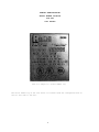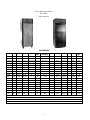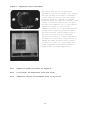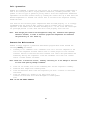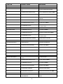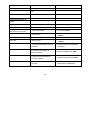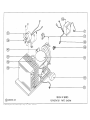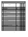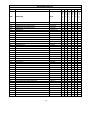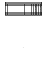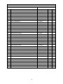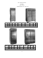
1
Randell Manufacturing, Inc.
This manual provides information on installation, operating, maintenance,
troubleshooting & replacement parts for
2000 SERIES
REACH-INS
NOTIFY CARRIER OF DAMAGE AT ONCE.
It is the responsibility of the consignee to inspect the container upon receipt of same
and to determine the possibility of any damage, including concealed damage. Randell
suggests that if you are suspicious of damage to make a notation on the delivery
receipt. It will be the responsibility of the consignee to file a claim with the carrier. We
recommend that you do so at once.
520 S. Coldwater Road Weidman, Ml 48893-9683
Phone 1-800-621-8560 Fax 1-800-634-5369 www.randell.com
TABLE OF CONTENTS
Page 2
.............................................................................…………...Congratulations
Page 3 .
................................................... . …………………Factory Correspondence
Page 4
....................................................…………………. Serial Number Location
Page 5
.....................................................…………………........ Unit Specifications
Page 8
................................................………………….. Randell Limited Warranty
Page 11
...................................................………………................... Unit Installation
Page 15
........................................................……………................... Unit Operation.
Page 15
................................................…………………...Preventative Maintenance
Page 17
..........................................................……………................ Troubleshooting
Page 26
.........................................................……………....................... Part Figures
Page 43
..................................……………………… Appendix A Heated Reach-ins
Congratulations on your recent purchase of Randell food service equipment, and welcome
to the growing family of satisfied Randell customers.
Our reputation for superior products is the result of consistent quality craftsmanship.
From the earliest stages of product design, to successive steps in fabrication and
assembly, rigid standards of excellence are maintained by our staff of designers,
engineers, and skilled employees.
Only the finest heavy-duty materials and parts are used in the production of Randell
brand equipment. This means that each unit, given proper maintenance, will provide
years of trouble free service to its owner.
In addition, all Randell food service equipment is backed by one
of the best warranties in the food service industry and by our
professional staff of service technicians.
2
Retain this manual for future reference.
Notice: Due to a continuous program of product improvement, Randell Manufacturing
reserves the right to make changes in design and specifications without prior
notice.
Notice: Please read the entire manual carefully before
installation.
If certain recommended procedures are not followed, warranty
claims will be denied.
Model Number
Serial Number
Installation Date
______________________
______________________
______________________
Randell Manufacturing
Service and Parts Hot Line
1-800-621-8560
3
RANDELL MANUFACTURING
SERIAL NUMBER LOCATION
FOR THE
2000 SERIES
This is a sample of a serial number tag.
The serial number tag on the 2000 series is located inside the refrigerated base on
the far left side of the unit.
4
Unit Specifications
For The
2000 Series
2000 SERIES
MODEL
L
D
H
DOORS
CUBIC
FEET
SHELVES
QTY/SQ. FT
HP**
BTU/HR
VOLT
2010
30"
33.5"
81.25"
1
24
3/11.75'
1/4
1740*
115/60/1
6.9
5-15P
395
2010D
30"
33.5"
81.25"
(2)1/2 SIZE
12/10
4/15.25"***
1/2
2180*
115/60/1
10.4
5-20P
495
2010DR
30"
33.5"
81.25"
(2)1/2 SIZE
12/10
4/15.25"***
1/2
2180*
115/60/1
7
N/A
445
201 OF
30"
33.5"
81.25"
1
24
3/11.75'
1/2
2180*
115/60/1
9.3
5-15P
425
2010FP
30"
35.75"
81.25"
2
24
3/17.5
1/2
2180*
115/60/1
9.3
5-15P
425
2010FPR
30"
35.75"
81.25"
2
24
3/17.5
1/2
2180*
115/60/1
5
N/A
425
2010FR
30"
33.5"
81.25"
1
24
3/11.75'
1/4
2180*
115/60/1
5
N/A
345
2010P
30"
35.75"
81.25"
2
24
3/11.75'
1/3
1740*
115/60/1
8.6
5-15P
395
2010PR
30"
35.75"
81.25"
2
24
3/11.75'
1/4
1740*
115/60/1
2
N/A
345
2010R
30"
33.5"
81.25"
1
24
3/11.75'
1/4
1740*
115/60/1
2
N/A
345
2011
30"
33.5"
81.25"
1
24
3/11.75'
1/4
1740*
115/60/1
6.9
5-15P
395
2011F
30"
33.5"
81.25"
1
24
3/11.75'
1/2
2180*
115/60/1
9.3
5-15P
425
2011FR
30"
33.5"
81.25"
1
24
3/11.75'
1/2
2180*
115/60/1
5
N/A
345
2011R
30"
33.5"
81.25"
1
24
3/11.75'
1/4
1740*
115/60/1
2
N/A
345
2135
35"
34.5"
84"
1
31
N/A
1/3
2300*
115/60/1
8.6
5-15P
850
2135R
35"
34.5"
84"
1
31
N/A
1/3
2300*
115/60/1
2
N/A
800
2235
35"
34.5"
84"
1
31
N/A
3/4
2180*
115/60/1
12
5-20P
880
2235R
35"
34.5"
84"
1
31
N/A
1/2
2180*
115/60/1
5
N/A
830
*Based on 90F ambient +20F evaporator for refrigerators and -10F for freezers
** Condensing units specified for remote units are recommendations only.
***lncludes bottom of each section as one shelf.
Note: All remote reach-ins come standard on 6" legs in lieu of casters.
5
AMP NEMA
SHIP
WT
2000 SERIES
L
D
H
DOORS
CUBIC
FEET
SHELVES
QTY/SQ FT.
HP
BTU/HR
VOLT
AMP
NEMA
SHIP
WT
2020
2020D
2020DR
2020F
2020FP
55"
55"
55"
55"
55"
33.5"
33.5"
33.5"
33.5"
35.75"
81.25"
81.25"
81.25"
81.25"
81.25"
2
(2)full size
(2)full size
2
4
47
47
47
47
47
6/26'
8/26'
8/26'
6/26'
6/26'
1/3
3/4
3/4
3/4
3/4
2300*
4020*
4020*
4020*
4020*
115/60/1
115/60/1
115/60/1
115/60/1
115/60/1
8.6
15.4
7
15.4
15.4
5-15P
5-20P
N/A
5-15P
5-15P
595
690
640
620
620
2020FPR
2020FR
2020P
2020PR
55"
55"
55"
55"
35.75"
33.5"
35.75"
35.75"
81.25"
81.25"
81.25"
81.25"
4
2
4
4
47
47
47
47
6/26'
6/26'
6/26'
6/26'
3/4
3/4
1/2
1/3
4020*
4020*
2300*
2300*
115/60/1
115/60/1
115/60/1
115/60/1
7
7
11.7
3
N/A
N/A
5-15P
N/A
570
570
595
545
2020R
2021
2021F
2021FR
2021 R
55"
55"
55"
55"
55"
33.5"
33.5"
33.5"
33.5"
33.5"
81.25"
81.25"
81.25"
81.25"
81.25"
2
2
2
2
2
47
47
47
47
47
6/26'
6/26'
6/26'
6/26'
6/26'
1/3
1/3
3/4
3/4
3/4
2300*
2300*
4020*
4020*
2300*
115/60/1
115/60/1
115/60/1
115/60/1
115/60/1
3
8.6
15.4
7
3
N/A
5-15P
5-15P
N/A
N/A
545
595
620
570
545
2022
55"
31.5"
81.25"
2
47
6/26'
1/3
2300*
115/60/1
8.6
5-15P
605
2022P
2022PR
2022R
55"
55"
55"
31.75"
31.75"
31.5"
81.25"
81.25"
81.25"
4
4
2
47
47
47
6/26'
6/26'
6/26'
1/2
1/3
1/3
2300*
2300*
2300*
115/60/1
115/60/1
115/60/1
11.7
3
3
5-15P
N/A
N/A
605
555
555
2168
2168R
2268
2268R
68"
68"
68"
68"
34.5"
34.5"
34.5"
34.5"
84"
84"
84"
84"
2
2
2
2
66
66
66
66
N/A
N/A
N/A
N/A
1/2
1/2
1
****
2180*
2180*
4900*
****
115/60/1
115/60/1
115/60/1
****
11.7
3
9.7
****
5-20P
N/A
14-20P
N/A
1275
1205
1310
1260
MODEL
*Based on 90F ambient +20F evaporator for refrigerators and -10F for freezers
** Condensing units specified for remote units are recommendations only.
***Includes bottom of each section as one shelf.
****Consult factory for recommended condensing unit specifications.
Note: All remote reach-ins come standard on 6" legs in lieu of casters.
6
2000 SERIES
MODEL
L
D
2030
2030F
2030FR
2030P
2030PR
2030R
2031
2031 R
83"
83"
83"
83"
83"
83"
83"
83"
33.5"
33.5"
33.5"
35.75"
35.75"
33.5"
33.5"
33.5"
H
DOORS
CUBIC
FEET
SHELVES
QTY/SQ FT
HP**
BTU/HR*
VOLT
81.25"
3
69
9/39'
1/2
2180*
115/60/1
81.25"
3
69
9/39'
1
4900*
115/60/1
81.25"
3
69
9/39'
***
***
***
81.25"
6
69
9/39'
1/2
2180*
115/60/1
81.25"
6
69
9/39'
1/2
2180*
115/60/1
81.25"
3
69
9/39'
1/2
2180*
115/60/1
81.25"
3
69
9/39'
1/2
2180*
115/60/1
81.25"
3
69
9/39'
1/2
2180*
115/60/1
*Based on 90F ambient +20F evaporator for refrigerators and -10F for freezers
** Condensing units specified for remote units are recommendations only.
***Consult factory for recommended condensing unit specifications.
Note: All remote reach-ins come standard on 6" legs in lieu of casters.
7
AMP
NEMA
SHIP
WT
11.7
9.7
***
11.7
4
2
11.7
2
5-15P
5-15P
N/A
5-15P
N/A
N/A
5-15P
N/A
800
840
790
800
750
750
800
750
Randell Manufacturing, Inc.
Warranty Policies
Parts Warranty
Randell warrants all component parts of manufactured new equipment to be free of defects
in material or workmanship, and that the equipment meets or exceeds reasonable industry
standards of performance for a period of one year from the date of shipment from any
Randell factory, assembly plant or warehouse facility.
Note:
Warranties are effective from date of shipment, with a thirty day window to allow
for shipment, installation and set up. In the event equipment was shipped to a site
other than the final installation site, Randell will warranty for a period of three
months following installation, with proof of starting date, up to a maximum of eighteen
months from date of purchase.
Component parts warranty does not cover glass breakage or gasket replacement. Randell
covers all shipping cost related to component part warranty sent at regular ground rates
(UPS, USPS).
Freight or postage incurred for any express or specialty methods of shipping are the
responsibility of the customer.
Labor Coverage
In the unlikely event a Randell manufactured unit fails due to defects in materials or
workmanship within the first ninety days, Randell agrees to pay reasonable labor
incurred. During the first ninety days work authorizations are not required for in
warranty repairs. However, repair times are limited to certain flex rate schedules and
hours will be deducted from service invoices if they exceed allowed times without prior
approval and a work authorization number. Warranties are effective from date of
shipment, with a 30 day window to allow for shipment, installation and setup.
Where equipment is shipped to any site other than final installation Randell will honor
the labor warranty for a period of ninety days following installation with proof of
starting date, up to a maximum of nine months from date of purchase. Travel time is
limited to one hour each direction or two hours per invoice. Any travel time exceeding
two hours will be the responsibility of the customer.
Note: Temperature adjustments are not covered under warranty, due to the wide range
of ambient conditions.
8
Five Year Extended Compressor Warranty
United States installations only:
Randell will pay for the replacement compressor only. Freight, labor, refrigerant,
handling and all other miscellaneous charges are the responsibility of the customer.
Randell will fulfill its warranty obligation by using one of the four methods
provided
below, which will be selected by the Randell in house service technician:
1.
Provide reimbursement to servicing customer for the cost of the locally obtained
replacement compressor in exchange for the return of the defective compressor
returned to Randell freight prepaid. Randell does limit the amount of reimbursement
allowed and does require a copy of the local supply house bill for replacement
compressor.
Customer should not pay servicing agent up front for compressor.
2. Provide repair at the manufacturing facility by requiring that the defective unit
be sent back to Randell freight prepaid. Perform repair at the expense of Randell
and ship the item back to job location freight collect.
3. Furnish a replacement compressor freight collect in exchange for the return of the
defective compressor sent back freight prepaid.
4. Furnish complete condensing unit or replacement package
freight collect in exchange for the return of the defective compressor sent back
freight prepaid, (decisions based on whether or not to send complete condensing unit
will be made by Randell in-house service technician).
Export Warranty
Our export warranties will cover all non electrical parts for the period of one year
from the date of shipment to be free of defects in material or workmanship. Electrical
parts are also covered if ordered and operated on 60 Hz. Electrical components, ordered
and operated on 50 Hz, are warranted for the first 90 days from shipment only. Service
labor is covered for the first 90 days with authorization from factory prior to service.
Warranty is automatically initiated 60 days from ship date. Inbound costs on any factory
supplied items would be the responsibility of the customer. Adherence to recommended
equipment maintenance procedures, according to the owners manual provided with each
unit, is required for this warranty to remain in effect, and can have a substantial
effect on extending the service life of your equipment. Equipment abuse voids any
warranty. Extended warranties are not available for parts, labor or compressors on units
shipped outside the United States.
9
Freight Damage
Any and all freight damage that occurs to a Randell piece of equipment as a result of
carrier handling is not considered warranty, and is not covered under warranty
guidelines. Any freight damage incurred during shipping needs to have a freight claim
filed by the receiver with the shipping carrier (note all damages on freight bill at
time of delivery). Internal or concealed damage may fall under Randell's responsibility
dependent upon the circumstances surrounding each specific incident and are at the
discretion of the Randell in-house service technician.
Gasket Coverage
Randell does not cover gaskets under warranty. Gaskets are a maintenance type component
that are subject to daily wear and tear and are the responsibility of the owner of the
equipment. Because of the unlimited number of customer related circumstances that can
cause gasket failure all gasket replacement issues are considered non-warranty. Randell
recommends thorough cleaning of gaskets on a weekly basis with a mild dish soap and warm
water. With proper care Randell gaskets can last up to two years, at which time we
recommend replacement of all gaskets on the equipment for the best possible performance.
NOTICE: FOOD LOSS IS NOT COVERED UNDER WARRANTY
10
Unit Installation
A. Receiving Shipment
Upon arrival, examine the exterior of the shipping crate for signs of abuse. It is
advisable that the shipping crate be partially removed, in order to examine the cabinet
for any possible concealed damages which might have occurred during shipment. If no
damages are evident, replace the crate in order to protect the unit during storage and
local delivery. If the unit is damaged, it should be noted on the delivery slip or bill
of lading and signed to that effect. A claim must be filed immediately against the
carrier indicating the extent and estimated cost of damage occurred.
B. Electrical Supply
The wiring should be done by a qualified electrician in accordance with local electrical
codes. A properly wired, and grounded outlet will assure proper operation. Please
consult the data plate attached to the compressor to ascertain the correct electrical
requirements. Supply voltage and amperage requirements are located on the serial number
tag located inside the far left door.
Note: It is important that a voltage reading be made at the
compressor motor electrical connections, while the unit is in operation, to verify
that the correct voltage required by the compressor is being supplied. Low or high
voltage can detrimentally affect operation and thereby void its warranty.
Note: It is important that your unit has its own dedicated line. Condensing units are
designed to operate with a voltage fluctuation of plus or minus 10% of the voltage
indicated on the unit data plate. Burn out of a condensing unit due to exceeding
voltage limits will void the warranty.
C. Door Inspection
1. Check doors/drawers to ensure that they are sealing properly.
2. Check doors for proper alignment (see figure D. page 14).
3. Check doors to ensure that they open and shut freely.
11
D. Locating Your New Unit
The following conditions should be considered when selecting a location for your
unit:
1.
Floor load - The area on which the unit will rest must be free of vibration and
suitably strong enough to support the combined weights of the unit plus the maximum
product load weight, which are provided in the table below:
MODEL
2021FR
2021R
2022
2022P
2022PR
2022R
2030
2030F
2030FR
2030P
2030PR
2030R
2031
2031R
2135
2135R
2168
2168R
2235
2235R
2268
2268R
2010
2010D
2.
3.
CUBIC
FT
47
47
47
47
47
47
69
69
69
69
69
69
69
69
31
31
66
66
31
31
66
66
24
12/10
FACTOR
35
35
35
35
35
35
35
35
35
35
35
35
35
35
35
35
35
35
35
35
35
35
35
35
WEIGHT
POUNDS
570
545
605
605
555
555
800
840
790
800
750
750
800
750
850
800
1275
1205
880
830
1310
1260
395
495
TOTAL
CAPACITY
2215
2190
2250
2250
2200
2200
3215
3255
3205
3215
3165
3165
3215
3165
1935
1885
3585
3515
1965
1915
3620
3570
1235
1265
MODEL
2010DR
2010F
2010FP
2010FPR
2010FR
2010P
2010PR
2010R
2011
2011F
2011FR
2011R
2020
2020D
2020DR
2020F
2020FP
2020FPR
2020FR
2020P
2020PR
2020R
2021
2021F
CUBIC
FT
12/10
24
24
24
24
24
24
24
24
24
24
24
47
47
47
47
47
47
47
47
47
47
47
47
FACTOR
35
35
35
35
35
35
35
35
35
35
35
35
35
35
35
35
35
35
35
35
35
35
35
35
WEIGHT
POUNDS
445
425
425
425
345
395
345
345
395
425
345
345
595
690
640
620
620
570
570
595
545
545
595
620
TOTAL
CAPACITY
1215
1265
1265
1265
1185
1235
1185
1185
1235
1265
1185
1185
2240
2335
2285
2265
2265
2215
2215
2240
2190
2190
2240
2265
Clearance - There must be a combined total of at least 3" clearance on all sides of
the unit.
Ventilation - The air cooled self contained unit requires a sufficient amount of cool
clean air. Avoid placing the unit near heat generating equipment such as ovens,
ranges, heaters, fryers, steam kettles, etc. and out of direct sunlight. Avoid
locating the unit in an unheated room or where the room temperature may drop below
55° F or above 90° F.
12
E. Installation Checklist
After the final location of the
checklist prior to start up:
1.
2.
3.
4.
5.
6.
7.
8.
unit
has
been
determined
refer
to
the
following
Check all exposed refrigeration lines to ensure that they are not kinked, dented or
rubbing together.
Check that condenser and evaporator fans rotate freely without striking any
stationary members.
Unit must be properly leveled.
Plug in unit and turn on main on/off switch.
Turn on cold control located inside the base.
Refer to the front of this manual for serial number location. Please record this
information in your manual on page 3 now. It will be necessary when ordering
replacement parts or requesting warranty service.
Confirm that unit is holding temperature. Set controls to desired temperature for
your particular ambient and altitude (See figure A.).
Allow your unit to operate for approximately 2 hours before putting in food this
allows interior to cool down to storage temperature.
Note: All motors are oiled and sealed.
Note: All self-contained models are shipped from the factory with the service valves
open ready for operation.
13
Figure B - Temperature control adjustments
The control knob allows for temperature
adjustments, with in the cabinet only. Turning
the knob clockwise will result in increased
cooling. Keep the arrow on the knob pointed
within the green arc. Turning it clockwise
beyond the green can result in freeze-up, while
turning it counterclockwise beyond the green
will shut the compressor off. If your cabinet
temperature remains to warm and your
temperature control is at the maximum setting
you may need to adjust the pressure control.
Your units pressure control should be set at
the time of installation by a qualified
installation contractor. If minor adjustments
are needed at a later date, adjust control by
turning the right adjusting screw clockwise
(1/4 turn at a time) to a lower number for
colder temperature and counterclockwise to a
higher number for warmer temperature.
Note:
Numbers are pounds of pressure not degrees F.
Note:
Do not adjust the differential screw (Left screw).
Note:
Temperature Controls located behind louver on top of unit.
14
Unit Operation
Randell has attempted to preset the cold control for an average interior temperature of
38°F at the factory but due to varying ambient conditions, including elevation, food
product as well as type of operation you may need to alter this temperature. Additional
adjustments can be made (within limits) by turning the control dial up or down until the
desired temperature is reached. The control dial is located on the evaporator housing
inside the base.
Your reach-in will maintain proper temperatures when utilized properly. It is strongly
recommended that the doors be kept closed as much as possible. This is especially
important in the summer and in kitchens exceeding 80° F.. Do not leave the covers open
for prolonged periods of time. Make sure doors close properly after each use.
Note:
Even though your reach-in was designed for heavy use, excessive door openings
should be avoided, in order to maintain proper box temperature and eliminate
the possibility of coil freeze up.
Preventive Maintenance
Randell strongly suggests a preventive maintenance program which would include the
following Monthly procedures:
1. Cleaning of all condenser coils. Condenser coils are a critical component in the
life of the compressor and must remain clean to assure proper air flow and heat
transfer. Failure to maintain this heat transfer will affect unit performance and
eventually destroy the compressor. Clean the condenser coils with coil cleaner
and/or a vacuum cleaner and brush.
Note: Brush coil in direction of fins, normally vertically as to not damage or restrict
air flow from passing through condenser.
2.
3.
4.
Clean all fan blades, both on the condensing unit and the evaporator assembly.
Lubricate door hinges with lithium grease.
Clean and disinfect drain lines and evaporator pan with a solution of warm water
and bleach.
5. Clean all gaskets on a weekly if not daily basis with a
solution of warm water and a mild detergent to extend gasket
life.
NOTE: DO NOT USE SHARP UTENSILS
15
Recommended cleaners for your stainless steel include the following:
JOB
CLEANING AGENT
COMMENTS
Routine cleaning
Soap, ammonia, detergent
Medallion
Apply with a sponge or cloth
Fingerprints and smears
Arcal 20, Lac-0-Nu,Ecoshine
Provides a barrier film
Stubborn stains and
discoloration
Cameo, Talc, Zud, First
impression
Rub in the direction of the polish
lines
Greasy and fatty acids, blood,
Easy-Off, De-grease It, Oven aid Excellent removal on all finishes
burnt-on foods
Grease and oil
Any good commercial detergent
Apply with a sponge or cloth
Restoration/Passivation
Benefit, Super Sheen
Good idea monthly
Reference: Nickel Development Institute, Diversey Lever, Savin, Ecolab, NAFEM
Do not use steel pads, wire brushes, scrapers or chloride cleaners to clean your
stainless steel.
CAUTION: DO NOT USE ABRASIVE CLEANING SOLVENTS, NEVER USE HYDROCHLORIC ACID
(MURIATIC ACID) ON STAINLESS STEEL.
Proper maintenance of equipment is the ultimate necessity in preventing costly repairs. By
evaluating each unit on a regular schedule you can often catch and repair minor problems
before they completely disable the unit and become burdensome on your entire operation.
For more information on preventive maintenance consult your local service company or CEFSA
member. Most repair companies offer this service at very reasonable rates to allow you the
time you need to run your business along with the peace of mind that all your equipment
will last throughout its expected life. These services often offer guarantees as well as
the flexibility in scheduling of maintenance for your convenience. Randell believes
strongly in the products it manufacturers and backs those products with one of the best
warranties in the industry. We believe with the proper maintenance and use you will
realize a profitable return on your investment and years of satisfied service.
16
SYMPTOM
POSSIBLE CAUSE
PROCEDURE
UNIT DOESN'T RUN
1. NO POWER TO UNIT.
1. PLUG IN UNIT.
2. TEMPERATURE CONTROL TURNED
OFF.
2. CHECK TEMPERATURE CONTROL.
3. TEMPERATURE CONTROL FAULTY.
3. TEST TEMPERATURE CONTROL. SEE #4
4. COMPRESSOR OVERHEATED.
4. CLEAN CONDENSER COIL. SEE #1
5. CONDENSER FAN FAULTY.
5. SERVICE CONDENSER FAN MOTOR.
SEE #7
6. OVERLOAD PROTECTOR FAULTY.
6. TEST OVERLOAD. SEE #10
7. COMPRESSOR RELAY FAULTY.
7. TEST RELAY. SEE #10
8. CALL FOR SERVICE AT
8. COMPRESSOR FAULTY.
1-800-621-8560.
UNIT SHORT CYCLES
1. CONDENSER COIL DIRTY.
1. CLEAN COIL. SEE #1
2. CONDENSER FAN FAULTY.
2. SERVICE FAN AND MOTOR. SEE #7
3. CALL FOR SERVICE AT
3. COMPRESSOR FAULTY.
UNIT RUNS CONSTANTLY
UNIT NOT COLD ENOUGH
1-800-621-8560.
4. OVERLOAD REPEATEDLY TRIPPING.
4. CHECK OUTLET VOLTAGE.
1. FROST BUILD UP.
1. DEFROST EVAPORATOR.
2. DOOR NOT SEALING PROPERLY.
2. CHECK DOOR. SEE #3
3. DOOR GASKET DAMAGED.
3. REPLACE GASKET.
4. CONDENSER COIL DIRTY.
4. CLEAN COIL. SEE #1
5. CONDENSER FAN FAULTY.
5. SERVICE CONDENSER MOTOR. SEE #7
1. TEMPERATURE CONTROL SET TOO
HIGH.
1. LOWER SETTING.
2. TEMPERATURE CONTROL FAULTY.
2. TEST CONTROL. SEE #4
3. CONDENSER COIL DIRTY.
3. CLEAN COIL. SEE #1
4. DOOR NOT SEALING PROPERLY.
4. CHECK DOOR. SEE #3
5. DOOR GASKET DAMAGED.
5. REPLACE DOOR GASKET.
6. EVAPORATOR FAN FAULTY.
6. SERVICE EVAPORATOR FAN. SEE #5
7. EVAPORATOR ICED UP.
7. CHECK DOOR SEE #3
8. REFRIGERANT LEAKING OR
8. CALL FOR SERVICE AT 1-800-621-
CONTAMINATED.
8560.
18
SYMPTOM
POSSIBLE CAUSE
PROCEDURE
UNIT TOO COLD
1. TEMPERATURE CONTROL SET TOO
LOW.
1. ADJUST CONTROL.
2. TEMPERATURE CONTROL FAULTY.
2. TEST CONTROL. SEE #4
1. BREAKER STRIPS FAULTY.
1. INSPECT STRIPS.
2. TEMPERATURE SET TOO LOW
2. RAISE SETTING.
1. DRAIN TUBE CLOGGED.
1. CLEAN DRAIN. SEE #2
MOISTURE AROUND DOOR OR
FRAME.
ICE IN DRAIN PAN OR WATER IN
BOTTOM OF UNIT OR FLOOR
2. ADJUST LEVELING FEET SEE DIAGRAM
2. UNIT NOT LEVEL
UNIT NOISY
A PAGE 13.
ADJUST LEVELING FEET SEE DIAGRAM
1. UNIT NOT LEVEL
A PAGE 13.
2. COMPRESSOR MOUNTINGS LOOSE OR
HARDENED.
2. TIGHTEN OR REPLACE COMPRESSOR
MOUNTINGS.
3. CONDENSER FAN DAMAGED OR
FITTING FAN SHROUD.
4. EVAPORATOR FAN DAMAGED OR
HITTING FAN SHROUD.
5. MECHANICAL COMPARTMENT LOUVER
RATTLING.
3. INSPECT CONDENSER FAN. SEE #7
4. INSPECT EVAPORATOR FAN. SEE #5
5. BEND OR ALIGN TABS TO REDUCE
NOISE. REPLACE IF NECESSARY.
19
1. Cleaning condenser coil.
An accumulation of dirt and dust
prevents the condenser coil from
removing, making your unit cool poorly,
run constantly, or even stop completely
if the compressor overheats. Clean coil
using a vacuum cleaner with a wand
attachment. If the coil is greasy, wash
it with warm soapy water and a bristle
brush, taking care not to drip water on
other parts of your unit.
2. Cleaning drain and drain pan.
Clean the drain using an oven baster to force a solution of hot water and baking soda or
bleach into the opening. To clear a stubborn clog, insert a length of 1/4" round plastic
tubing into the drain and push it through to the drain pan, then pull it out. Wash the
pan regularly with a solution of warm baking soda and water.
3. Checking the door seal.
Open the door and examine all four sides
of the door gasket for tears. Feel the
gasket for brittleness or cracks. If the
gasket shows damage replace it. If not,
close the door and check the seal between
gasket and cabinet for obvious gaps. Next
open the door and shut it on a dollar bill
slowly pull it out of the door. If the
gasket seals properly, you will feel
tension as it grips the bill. Repeat this
test all around the door. If the gasket
doesn't seal tightly, replace gasket after first checking the door for sagging,
warping.
20
4. Testing and replacing the temperature control.
Unplug the unit and remove the temperature control knob. Remove the screws securing the
fan shroud to the evaporator coil assembly, next remove the screws securing the
temperature control to the fan shroud. Taking care not to bend the capillary line, pull
off the wire connectors. Now you are ready to test for continuity.
Set your multimeter at RX1, Touch a probe to each
terminal. With the control at its the tester should
indicate a closed circuit. Turn off the control
then retest; the tester should indicate an open
circuit. To install a new temperature control, pull
the capillary line of the old control out of its
opening. Set the new control to its coldest setting
and carefully thread the capillary line into the
opening without kinking it. Attach the wires to the
terminals, screw the control in place and reattach
the dial.
5. Checking and testing the evaporator motor.
Remove the screws attaching the side to the
evaporator coil housing. Remove the bolts holding
the fan bracket to the coil assembly and Lift the
fan motor a few inches to remove the push on
connectors. Check blade for damage, replace if
necessary. Pull the blade off the motor shaft and
slide on a new blade, taking care not to reverse
the blade. Hold the blade horizontally and spin the
blade to check for binding in the motor. If the
blade does not spin freely, replace the motor. To
test the motor set a multimeter at RX1 and touch a
probe to each motor terminal. The meter should show
resistance. If not, install a new motor, and
reinstall the fan.
21
6. Testing and replacing programmable defrost timer.
With electric defrost it is critical that the defrost terminate at the earliest
possible time. The defrost timer controls the following events:
A. Evaporator fans stop.
B. Compressor stops after the pump down cycle.
C. Electric heaters are energized.
NOTE: 3-wire thermodisc (single pole double throw) is used to terminate defrost when
the coil is above freezing. A maximum defrost time should be programmed into the timer
in the event the defrost termination switch fails to terminate defrost.
To test defrost timer first,
examine dial to see if time on dial
is actual time, in case either the
power has been off, or the timer
motor is not advancing. Next,
advance the timer by hand until the
defrost cycle starts. After defrost
is terminated by the thermodisc
check to see that unit returns to
normal operation, after
approximately one half hour. If not
replace defrost timer or motor.
Visually inspect for broken or
loose wire connections to defrost
timer. If a defective connection is
found, tighten or repair
connection, if not check with
multimeter to confirm power is
reaching timer. If power is going
to timer troubleshoot timer, if not
trace for source of open circuit.
22
7. Servicing the condenser fan.
Inspect the condenser fan motor by removing the mechanical housing cover to gain access.
Unplug the unit. Clean the fan blade, and turn it to see if the blade rotates freely. If
the motor binds, replace it. If the blade is damaged, unscrew the nut that holds it to
the motor shaft and pull it off. Install a new fan blade, replacing any washers, and
tighten the nut.
To test the condenser fan motor disconnect
the wires to the fan motor. Set a multimeter at
RX10 and touch one probe to each terminal. The
multimeter needle should show approximately 45 to
50 ohms resistance; a lower reading means the
motor is faulty. Next set the meter at RX1000 and
touch one probe to the motor terminals and the
other one to any unpainted metal part of the unit.
If the meter needle moves, the motor is grounded
and should be replaced. To remove the motor
unscrew the bracket that holds the fan motor to
its housing, slide the motor out of the housing.
Remove the fan blade from the old motor and attach
it to the new motor, replacing any washers.
Install the new motor in its housing by screwing
the bracket in place. Reattach the wires to the
motor terminals.
8. Servicing the compressor.
The compressor is part of the sealed
refrigeration system and should be replaced by a
professional service technician. You can,
however, test the compressor and certain
components. Unplug the unit and remove the access
cover to the mechanical housing. A small box
mounted on the side of the compressor protects
the relay, overload protector and capacitor.
Release the wire retaining clip that holds the
cover in place and slip off the cover and the
clip.
23
To test the compressor relay pull the relay
straight off the compressor without twisting it. If
the relay has an external wire coil, hold the relay
so that the word top is up. Set the multimeter at
RX1 and place the probes on the terminals S and M.
the multimeter needle should not move. Next remove
the probe from M and place it on the side terminal
marked L. once again, the needle should not move.
Finally, remove the
probe from S and place it on M. the needle should
sweep across the scale, showing full continuity.
Now turn the relay upside down and perform the same
tests. You should get the opposite results:
continuity between terminals S and M and between S
and L; no continuity between M and L. if the relay
fails any of these tests, replace it: push the new relay onto the compressor terminals
and replace the terminal cover. If the relay passes these tests, test the overload
protector.
To remove the overload protector use a screwdriver to gently pry open the circular
spring clip that secures the overload protector to the compressor and snap out the
protector. Pull the two wire connectors off their terminals.
To test set a multimeter at RX1 and touch a probe
to each overload protector terminal. The
multimeter needle should sweep across the scale,
showing full continuity. If the overload protector
passes this test, test the compressor. If not
replace the overload protector. Reattach the pushon connectors to the new overload protector, clip
it in place on the compressor and replace the
terminal cover.
24
To test the compressor set a multimeter at RX1,
test each of the three terminal pins against
each of the other two. Each pair should show
continuity. Then, with the -multimeter set at
RX1000, place one probe against the metal
housing of the compressor; if necessary, scrape
off a little paint to ensure contact with bare
metal. Place the other probe on each of the
three terminals in turn. If any of the three
terminals shoes continuity with the housing, the
compressor is grounded. If the compressor fails
either test, call for service. If it passes the
tests, reinstall the overload protector, relay,
terminal cover and mechanical housing cover.
25
o:/drafting/service/reachin.dgn Aug. 27, 1998
14:00:24
o:/drafting/service/reachin.dgn Aug. 27, 1998
14:01:06
o:/drafting/service/reachin.dgn
Sep.
1, 1998
13:43:47
o:/drafting/service/reachin.dgn
Sep.
1, 1998
09:59:26
o:/drafting/ser-vice/reachin.dgn
Aug. 27, 1998
13:13:34
o:/drafting/service/reachin.dgn Aug. 27, 1998 13:12:53
o:/drafting/service/reachin.dgn Aug. 27, 1998 13:13:14
o:/drafting/service/reachin.dgn
Aug. 27, 1998
13:08:21
REACH-IN REFRIGERATOR
REPLACEMENT PARTS LIST
ITEM
DESCRIPTION
PART#
2
0
1
0
1
1
2
1
3
5
2
0
2
0
2
2
0
2
2
1
2
1
6
8
2
0
3
0
3
1
3
SET OF (4) CASTERS
001451
X
X
X
X
4
5
CASTER 6" NON-LOCKING
CASTER 6" LOCKING
HD-CST061
HD-CST060
X
X
X
X
X
X
X
X
9
UNIVERSAL TRAY SLIDES
UNIVPS
X
X
X
X
13
PILASTER ASSEMBLY
RP PIL2412
X
X
X
X
13A
14
PILASTER ASSEMBLY, W/CENTER SECTION
SHELVES POWDER COATED (22 X 25 1/4)
RP PIL2420
HD-SHL105
X
X
X
X
X
X
X
14A
SHELVES STAINLESS STEEL (22 X 25 1/4)
HD-SHL105SS
O
O
O
O
14B
SHELVES POWDER COATED NOTCHED SHELF, USED IN RH AND/OR
CENTER OPENING
HD-SHL106
X
X
X
17
POWER CORD 16/3 REFRIGERATOR 115V
EL-WIR461
X
X
X
X
18
SHELF CLIPS (SET OF 4) STAINLESS STEEL
HD-CLP150
X
X
X
X
X
X
44
DOOR & SNAP-IN GASKET
SEE SCHEDULE A1
X
X
44A
DOOR & SNAP-IN GASKET
SEE SCHEDULE A2
X
X
X
X
46
DOOR HINGE (SET OF 2)
HD-HIN400
X
X
X
X
X
X
47
DOOR HANDLE 12 3/4" (GLASS DOOR)
HD-HDL125Y
X
X
X
X
X
X
47A
DOOR HANDLE 12 3/4" (STAINLESS DOOR)
HD-HDL125
X
X
X
X
X
X
49
DOOR LOCK W/KEYS (GLASS DOOR)
HD-LCK150
X
X
X
X
X
X
49A
DOOR LOCK W/KEYS (STAINLESS DOOR)
HD-LCK206
X
X
X
X
X
X
53
ABS PLASTIC BREAKER STRIP (CAP ONLY)
PL-STR200
X
X
X
X
X
X
54
HEATER, MULLION HEATER (REFRIGERATOR ONLY)
EL-WIR122
X
X
X
54A
HEATER, PERIMETER HEATER
(SPLIT DOOR OR DRAWERS)
EL-WIR211
X
X
X
X
X
X
94
ALUMINUM END PANEL (SKIN) 31.25" X 75"
RP SKN001
X
X
X
X
X
X
95
95A
ALUMINUM AIR SHIELD
ALUMINUM AIR SHIELD
RP ASH001
RP ASH002
X
X
X
X
X
X
95B
ALUMINUM AIR SHIELD
RP ASH003
X
X
96
ALUMINUM AIR DIVERTER
RP ADV001
96A
96B
ALUMINUM AIR DIVERTER
ALUMINUM AIR DIVERTER
RP ADV002
RP ADV003
96C
102
GALVANIZED HOLD DOWN CLIPS FOR BLOWER BOX
LOUVER 1 PC 12.5" X 24.25"
RP HDC001
RP LVR201
102A
LOUVER 1 PC 12.5" X 49.25"
RP LVR202
102B
LOUVER 1 PC 12.5" X 77.25"
RP LVR203
108
113
EXPANSION VALVE (REFRIGERATOR)
THERMOMETER
RF-VLV300
HD-THR300
X
X
114
SOCKET, LIGHT BULB
EL LGT360
115
LAMP GUARD
HD-GRD1159
116
TEMPERATURE CONTROL
HD-CNT200
35
X
X
X
X
X
X
X
X
X
X
X
X
X
X
X
X
X
X
X
X
X
X
X
X
X
X
X
X
X
X
X
X
X
X
X
X
X
X
X
X
X
X
X
X
X
X
X
X
X
REACH-IN REFRIGERATOR
REPLACEMENT PARTS LIST
0
0
1
0
1
1
9
1
3
5
ITEM
DESCRIPTION
PART#
117
LOW PRESSURE CONTROL
RF-CNT700
130
130A
CONDENSING UNIT AEA4430YXAXB
CONDENSING UNIT AEA4440YXAXB
RF CON251
RF CON333A
130B
CONDENSING UNIT AKA4476YXAXC
RF CON503
131
COMPRESSOR
RF CMP010-134
131A
131B
COMPRESSOR
COMPRESSOR
RF CMP020
RFCMP200-134
134
134A
START COMPONENTS
START COMPONENTS
RF STR251
RF STR333
134B
START COMPONENTS
RF STR503
135
RECEIVER TANK
RF TNK001
X
X
135A
136
RECEIVER TANK
CONDENSER COIL
RF TNK503
RF COI251
X
X
136A
136B
CONDENSER COIL
CONDENSER COIL
RF C01333A
RF COI503
137
CONDENSER FAN MOTOR
RF FAN001
X
X
137A
138
CONDENSER FAN MOTOR
CONDENSER FAN BLADE
RF FAN751
RF FAN251
X
X
138A
140
CONDENSER FAN BLADE
FILTER DRIER
RF FAN004
RF-FLT250A
X
X
141
141A
150
EVAPORATOR PAN (S/S) 23.5" X 3" X 1.25"
EVAP PAN S/S
EVAP COIL ASSY
RP EPN001
RP EPN002
RP CSY201
X
X
X
X
150A
EVAP COIL ASSY
RP CSY223
152
EVAPORATOR COIL
RF-COI120C
X
X
155
INSULATED BOX COVER
RP CVR001
X
X
155A
158
INSULATED BOX COVER
EVAP FAN MOTOR
RP CVR002
EL-MTR057
X
159
EVAPORATOR FAN BLADE
RF-FAN005
161
EVAPORATO FAN SHROUD
RP SHD201
161A
162
EVAPORATOR FAN SHROUD
EVAP FAN MOTOR MOUNTING BRACKET
510
511
0
0
2
0
2
1
2
0
2
2
2
1
6
8
2
0
3
0
3
1
X
X
X
X
X
X
X
X
X
X
X
X
X
X
X
X
X
X
X
X
X
X
X
X
X
X
X
X
X
X
X
X
X
X
X
X
X
X
X
X
X
X
X
X
X
X
X
X
X
X
X
X
X
X
X
X
X
X
X
X
X
X
X
RP SHD223
RP BRK123
X
X
X
X
X
X
X
X
X
X
ON-OFF ROCKER SWITCH (NON-LIGHTED)
EL-SWT140
X
X
X
X
X
X
LIGHT SWITCH (BEHIND TOP DOOR HINGE)
EL-SWT150C
X
X
X
X
X
X
514
514A
2 FAN WIRE HARNESS W/SPADE ENDS
3 FAN WIRE HARNESS W/SPADE ENDS
EL-WIR002
EL-WIR003
X
X
X
X
X
X
580
LIGHT BULB 40 WATT
EL-LGT200
X
X
X
X
X
X
720
CAM LIFT BUSHINGS
HD HIN400-2
X
X
X
X
X
X
727
GALVANIZED HAT CHANNEL 24.25"
RP GHC001
X
XA
36
REACH-IN REFRIGERATOR
REPLACEMENT PARTS LIST
ITEM
DESCRIPTION
PART#
2
0
1
0
1
2
1
3
5
1
727A
727B
749
GALVANIZE HAT CHANNEL 49.25"
GALVANIZE HAT CHANNEL 77.25"
RAMP
RP GHC002
RP GHC003
RP RMP001
37
2
0
2
0
2
2
0
2
2
2
1
6
8
1
X
2
0
3
0
3
1
X
X
X
X
X
REACH-IN FREEZER MODELS
REPLACEMENT PARTS
FREEZER
DESCRIPTION
PART #
2010F
2011F
3
SET OF (4) CASTERS
001451
X
X
X
4
CASTER 6" NON-LOCKING
HD-CST061
X
X
X
5
CASTER 6" LOCKING
HD-CST060
X
X
X
9
UNIVERSAL TRAY SLIDES
UNIVPS
X
X
X
13
PILASTER ASSEMBLY
RP PIL2412
X
X
X
ITEM
2235
2020F
2021 F
2268
2030F
2031 F
13
A PILASTER ASSEMBLY, W/CENTER SECTION
RP PIL2420
X
X
X
14
SHELVES POWDER COATED (22 X 25 1/4)
HD-SHL105
X
X
X
14
A SHELVES STAINLESS STEEL (22 X 25 1/4)
HD-SHL105SS
O
O
O
14
SHELVES POWDER COATED NOTCHED SHELF, USED
B IN RH AND/OR CENTER OPENING
HD-SHL106
X
X
X
EL-WIR800
X
17
POWER CORD 12/3 FREEZER 115V
17
A POWER CORD 12/4 FREEZER 208/230
X
X
X
EL-WIR
X
18
SHELF CUPS (SET OF 4) S/S
HD-CLP150
X
44
DOOR & SNAP-IN GASKET
SEE SCHEDULE A1
X
44
A DOOR & SNAP-IN GASKET
SEE SCHEDULE A2
X
X
X
X
X
X
46
DOOR HINGE (SET OF 2)
HD-HIN400
X
X
X
X
X
47
DOOR HANDLE 12 3/4" (GLASS DOOR)
HD-HDL125Y
X
X
X
X
X
HD-HDL125
X
X
X
X
X
HD-LCK150
X
X
X
X
X
HD-LCK206
X
X
X
X
X
47
49
49
A DOOR HANDLE 12 3/4" (STAINLESS DOOR)
DOOR LOCK W/KEYS (GLASS DOOR)
A DOOR LOCK W/KEYS (STAINLESS DOOR)
53
ABS PLASTIC BREAKER STRIP (CAP ONLY)
PL-STR200
X
X
X
X
X
54
HEATER, FRAME PERIMETER
EL-WIR158
X
X
X
X
X
EL-WIR211
X
X
X
X
X
X
X
X
X
X
54
HEATER, PERIMETER HEATER (SPLIT DOOR OR
A DRAWERS)
94
ALUMINUM END PANEL (SKIN)
RP SKN001
X
X
95
ALUMINUM AIR SHIELD
RP ASH001
X
X
95
A ALUMINUM AIR SHIELD
RP ASH002
95
B ALUMINUM AIR SHIELD
RP ASH003
96
ALUMINUM AIR DIVERTER
RP ADV001
96
A ALUMINUM AIR DIVERTER
RP ADV002
96
B ALUMINUM AIR DIVERTER
RP ADV003
96
C GALVANIZED HOLD DOWN CLIPS FOR BLOWER BOX
RP HDC001
102
LOUVER 1 PC 12.5" X 24.25"
RP LVR201
102 A LOUVER 1 PC 12.5" X 49.25"
RP LVR202
102 B LOUVER 1 PC 12.5" X 77.25"
RP LVR203
108
RF-VLV404
EXPANSION VALVE (FREEZER)
38
X
X
X
X
X
X
X
X
X
X
X
X
X
X
X
X
X
X
X
REACH-IN FREEZER MODELS
REPLACEMENT PARTS
FREEZER
ITEM
110
110
113
DESCRIPTION
PLUG (HUBBELL) 20 AMPS 240V
A FEMALE PLUG-HTD GLASS DOOR ONLY
THERMOMETER
PART#
2010F
2235
2011F
2020F
2268
2021F
EL-PLG8411
2030F
2031F
X
EL-WIR476A
HD-THR300
X
X
X
X
X
X
X
X
X
X
114
SOCKET, LIGHT BULB
EL LGT360
X
X
X
X
X
115
116
LAMP GUARD
TEMPERATURE CONTROL
HD-GRD1159
HD CNT100
X
X
X
X
X
X
X
X
X
X
117
DUAL PRESSURE CONTROL
RF-CNT725
X
X
X
X
X
118
118
THERMODISC (2-WIRE)L.H. COIL
A THERM-O-DISC 3-WIRE
RF-TRM001
RF-TRM002
X
X
X
X
X
X
X
X
X
X
X
X
X
119
EL-TMR120
X
X
130
130
CONDENSING UNIT AJA2422ZXAXB
A CONDENSING UNIT FJAF-A074-CAA-201
RF CON550
RF CON800
X
X
130
B CONDENSING UNIT FJAF-A100-CAV-201
RFCON1060Q
131
131
COMPRESSOR
A COMPRESSOR
RF CMP050-404P
RF CMP800
131
B COMPRESSOR
RFCMP1060
134
134
START COMPONENTS
A START COMPONENTS
RF STR550
RF STR800
134
B START COMPONENTS
RF STR1060
135
135
RECEIVER TANK
A RECEIVER TANK
RF TNK550
RF TNK800
135
B RECEIVER TANK
RF TNK1060
136
136
CONDENSER COIL
A CONDENSE COIL
RF COI550
RF COI800
136
B CONDENSE COIL
RF COI1060
137
137
CONDENSE FAN MOTOR
A CONDENSE FAN MOTOR
RF FAN014
RF MTR800
137
B CONDENSE FAN MOTOR
EL MTR1060
138
138
CONDENSE FAN BLADE
A CONDENSE FAN BLADE
RF FAN550
RF FAN801
138
B CONDENSE FAN BLADE
RF FAN 1060
140
141
DEFROST TIMER (120V)
FILTER DRIER
EVAP PAN (S/S) 23.5" X 3" X 1.25"
RF-FLT250A
RP EPN001
X
X
X
X
X
X
X
X
X
X
X
X
X
X
X
X
X
X
X
X
X
X
X
X
X
X
X
X
X
X
X
X
X
X
X
X
X
X
X
X
X
X
X
X
X
X
X
X
X
X
141
A EVAP PAN S/S
RP EPN002
150
150
EVAP COIL ASSY
A EVAP COIL ASSY
RP CSY201
RP CSY223
X
X
RF-COI120C
X
X
RP CVR001
RP CVR002
X
X
EL-MTR057
X
X
X
X
X
RF-FAN005
RP SHD201
X
X
X
X
X
X
X
X
X
X
X
X
X
152
155
155
158
159
161
EVAPORATOR COIL
INSULATED BOX COVER
A INSULATED BOX COVER
EVAP FAN MOTOR
EVAPORATOR FAN BLADE
A EVAPORATO FAN SHROUD
161
EVAPORATOR FAN SHROUD
RP SHD223
162
EVAP FAN MOTOR MOUNTING BRACKET
RP BRK123
39
X
X
REACH-IN FREEZER MODELS
REPLACEMENT PARTS
FREEZER
ITEM
413
DESCRIPTION
PART#
DEFROST ELEMENT (COMBO) LEFT COIL
EL-ELM500A
413
413
A
B
DEFROST ELEMENT (COMBO) RIGHT COIL
DEFROST HEATER
EL-ELM500B
EL-ELM501
413
C
DEFROST HEATER
EL WIR271
A
ON-OFF ROCKER SWITCH (NON-LIGHTED)
ON-OFF SWITCH, SINGLE THROW/DBL. POLE 240V
2010F
2020F
2030F
2235
2268
2011F
2021 F
2031 F
X
X
X
X
X
X
X
X
X
X
X
X
X
X
X
X
X
X
X
X
X
X
X
X
X
X
X
X
EL-SWT140
EL-SWT145S
X
X
LIGHT SWITCH
EL-SWT150C
X
X
2 FAN WIRE HARNESS W/SPADE ENDS
3 FAN WIRE HARNESS W/SPADE ENDS
EL-WIR002
EL-WIR003
X
X
580
LIGHT BULB 40 WATT
EL-LGT200
X
720
727
CAM LIFT BUSHINGS
GALVANIZED HAT CHANNEL 24.25"
HD HIN400-2
RP GHC001
X
X
510
510
511
514
514
A
727
A
GALVANIZE HAT CHANNEL 49.25"
RP GHC002
727
749
B
GALVANIZE HAT CHANNEL 77.25"
RAMP
RP GHC003
RP RMP001
OMITRON RELAY
EL RLY300
900
40
X
X
X
X
DUAL TEMPERATURE REACH-INS
REPLACEMENT PARTS
2010D
2020D
3
ITEM
SET OF (4) CASTERS
DESCRIPTION
001451
PART#
X
X
4
CASTER 6" NON-LOCKING
HD-CST061
X
X
5
CASTER 6" LOCKING
HD-CST060
X
X
9
UNIVERSAL TRAY SLIDES
UNIVPS
X
X
13
PILASTER ASSEMBLY
RP PIL2412
X
X
13A
PILASTER ASSEMBLY, W/CENTER SECTION
RP PIL2420
14
SHELVES POWDER COATED (22 X 25 1/4)
HD-SHL105
X
X
14A
SHELVES STAINLESS STEEL (22 X 25 1/4)
HD-SHL105SS
O
O
14B
SHELVES POWDER COATED NOTCHED SHELF, USED IN RH
AND/OR CENTER OPENING
HD-SHL106
17
POWER CORD 16/3 REFRIGERATOR 115V
EL-WIR461
X
X
18
SHELF CLIPS (SET OF 4) STAINLESS STEEL
HD-CLP150
X
X
44
DOOR & SNAP-IN GASKET
SEE SCHEDULE A1
X
44A
DOOR & SNAP-IN GASKET
SEE SCHEDULE A2
46
DOOR HINGE (SET OF 2)
HD-HIN400
X
X
47
DOOR HANDLE 12 3/4" (GLASS DOOR)
HD-HDL125Y
X
X
47A
DOOR HANDLE 12 3/4" (STAINLESS DOOR)
HD-HDL125
X
X
49
DOOR LOCK W/KEYS (GLASS DOOR)
HD-LCK150
X
X
49A
DOOR LOCK W/KEYS (STAINLESS DOOR)
HD-LCK206
X
X
53
ABS PLASTIC BREAKER STRIP (CAP ONLY)
PL-STR200
X
X
54
HEATER, MULLION HEATER (REFRIGERATOR ONLY)
EL-WIR122
X
X
54A
HEATER, FRAME PERIMETER
EL-WIR158
X
X
54B
HEATER, PERIMETER HEATER (SPLIT DOOR OR DRAWERS)
EL-WIR211
X
X
94
ALUMINUM END PANEL (SKIN) 31.25" X 75"
RP SKN001
X
X
95
ALUMINUM AIR SHIELD
RP ASH001
X
95A
ALUMINUM AIR SHIELD
RP ASH002
96
ALUMINUM AIR DIVERTER
RP ADV001
96A
ALUMINUM AIR DIVERTER
RP ADV002
96B
GALVANIZED HOLD DOWN CLIPS (BLOWER BOX)
RP HDC001
X
102
LOUVER 1 PC 12.5" X 24.25"
RP LVR201
X
102A
LOUVER 1 PC 12.5" X 49.25"
RP LVR202
108
EXPANSION VALVE
RF VLV408
108A
EXPANSION VALVE
RFVLV414
X
108B
EXPANSION VALVE
RF VLV404
X
110
PLUG (HUBBELL) 20 AMPS 240V FREEZER ONLY
EL PLG8411
110A
FEMALE PLUG-HTD GLASS DOOR ONLY
EL-WIR476A
113
THERMOMETER
HD-THR300
X
X
114
SOCKET, LIGHT BULB
EL LGT360
X
X
115
LAMP GUARD
HD-GRD1159
X
X
116
TEMPERATURE CONTROL
HD-CNT100
X
X
116A
TEMPERATURE CONTROL
HD-CNT200
X
X
117
LOW PRESSURE CONTROL
RF-CNT700
117A
DUAL PRESSURE CONTROL
RF-CNT725
118
THERMODISC (2-WIRE) LH. COIL
RF-TRM001
41
X
X
X
X
X
X
X
X
X
X
X
X
DUAL TEMPERATURE REACH-INS
REPLACEMENT PARTS
ITEM
DESCRIPTION
PART #
2010D
2020D
118A
119
THERM-O-DISC 3-WIRE
DEFROST TIMER (120V)
RF-TRM002
EL-TMR120
X
X
X
X
130
CONDENSING UNIT AJA2422ZXAXB
RF CON550
X
130A
131
CONDENSING UNIT FJAF-A074-CAA-201
COMPRESSOR, AJA2419ZXA
RF CON800
RF CMP050-404P
X
131A
COMPRESSOR, RS64C1E-CAA-1
RF CMP800
134
134A
START COMPONENTS
START COMPONENTS
RF STR550
RF STR800
X
135
RECEIVER TANK
RF TNK550
X
135A
136
RECEIVER TANK
CONDENSOR COIL
RF TNK800
RF COI550
X
136A
CONDENSOR COIL
RF COI800
137
137A
CONDENSOR FAN MOTOR
CONDENSOR FAN MOTOR
RF FAN014
RF MTR800
X
138
CONDENSOR FAN BLADE
RF FAN550
X
138A
140
CONDENSOR FAN BLADE
FILTER DRIER
RF FAN801
RF-FLT250A
X
141
EVAPORATOR PAN (S/S) 23.5" X 3" X 1.25"
RP EPN001
X
141A
150
EVAP PAN S/S
EVAP COIL ASSY
RP EPN002
RP CSY201
150A
EVAP COIL ASSY
RP CSY223
152
155
EVAPORATER COIL
INSULATED BOX COVER
RF-COI120C
RP CVR001
155A
INSULATED BOX COVER
RP CVR002
158
159
EVAP FAN MOTOR
EVAPORATOR FAN BLADE
EL-MTR057
RF-FAN005
X
X
161
EVAPORATER FAN SHROUD
RP SHD201
X
161A
162
EVAPORATOR FAN SHROUD
EVAP FAN MOTOR MOUNTING BRACKET
RP SHD223
RP BRK123
X
X
X
413
DEFROST HEATER
EL-ELM501
X
X
413A
510
DEFROST HEATER
ON-OFF ROCKER SWITCH (NON-LIGHTED)
EL WIR271
EL-SWT140
X
X
X
X
511
LIGHT SWITCH (BEHIND TOP DOOR HINGE)
EL-SWT150C
X
X
514
514A
2 FAN WIRE HARNESS W/SPADE ENDS
3 FAN WIRE HARNESS W/SPADE ENDS
EL-WIR002
EL-WIR003
X
580
LIGHT BULB 40 WATT
EL-LGT200
X
X
720
727
CAM LIFT BUSHINGS
GLAVANIZED HAT CHANNEL 24.25"
HD HIN400-2
RP GHC001
X
X
X
727A
GLAVANIZED HAT CHANNEL 49.25"
RP GHC002
42
X
X
X
X
X
X
X
X
X
X
X
X
X
X
X
X
X
X
X
Unit Specifications
For The
2000 Series
Heated Reach-ins 5 Roll-ins
MODE
L
2410
2420
MODEL
2335
2368
L
D
30"
55"
33.5"
33.5"
81.25"
1
24
.98/1.3
208/230/60
81.25"
2
47
1.47/1.95
208/230/60
* 1ST Number is for 208V, 2ND Number is for 230V
D
H
DOORS
84"
84"
1
2
L
35" 34.5"
68" 34.5"
H
DOORS
CUBIC FT
CUBIC
FT
35
72
kW*
VOLT
AMP*
NEMA
4.7/5.4
7/8.1
6-15P
6-15P
kW*
VOLT
AMP*
NEMA
.98/1.3
1.47/1.95
208/230/60
208/230/60
4.7/5.4
7/8.1
6-15P
6-15P
* 1ST Number is for 208V, 2ND Number is for 230V
44
SHIP
WT
425
650
SHIP
WT
425
650
Serial Number Location
The serial number tag for the heated units is located on the far left
inside of the base.
Unit Installation
Please refer to unit installation on page 11 of the manual.
Locating Your New Unit
The following conditions should be considered when selecting a
location for your unit:
1. Floor load - The area on which the unit will rest must be free of
vibration and suitably strong enough to support the combined weights
of the unit plus the maximum product load weight, which are provided
in the table below:
MODEL
CUBIC FT FACTOR
WEIGHT
POUNDS
TOTAL
CAPACITY
2335
35
35
425
1650
2368
2410
72
24
35
35
650
425
3170
1265
2420
47
35
650
2295
2. Clearance - There must be a combined total of at least 3"
clearance on all sides of the unit.
Unit Operation
Randell has attempted to preset the control at the factory but due to
varying ambient conditions, including elevation, food product as well as
type of operation you may need to alter the temperature. Additional
adjustments can be made (within limits) by turning the control dial up
or down until the desired temperature is reached. The control dial is
located on the top of the unit behind the access cover. Your heated
reach-in will maintain proper temperatures when utilized properly. It is
strongly recommended that the doors be kept closed as much as possible.
Make sure doors close properly after each use.
Note: Even though your heated reach-in was designed for heavy
use, excessive door openings should be avoided, in order to
maintain proper box temperature
45
Preventive Maintenance
Randell strongly suggests a preventive maintenance program which would include the
following Monthly procedures:
1.
2.
3.
4.
Cleaning of all stainless steel parts.
Clean all fan blades
Check and Lubricate door hinges with lithium grease.
Clean all gaskets on a weekly if not daily basis with a
solution of warm water and a mild detergent to extend gasket life.
Recommended cleaners for your stainless steel include the following:
JOB
CLEANING AGENT
COMMENTS
Routine cleaning
Soap, ammonia, detergent
Medallion
Apply with a sponge or cloth
Fingerprints and smears
Arcal 20,Lac-0-Nu,Ecoshine
Provides a barrier film
Stubborn stains and
discoloration
Cameo, Talc, Zud, First
impression
Rub in the direction of the polish
lines
Greasy and fatty acids, blood,
Easy-Off, De-grease It, Oven aid Excellent removal on all finishes
burnt-on foods
Grease and oil
Any good commercial detergent
Apply with a sponge or cloth
Restoration/Passivation
Benefit, Super Sheen
Good idea monthly
Reference: Nickel Development Institute, DiverseyLever, Savin, Ecolab, NAFEM
Do not use steel pads, wire brushes, scrapers or chloride cleaners to clean your
stainless steel.
CAUTION: DO NOT USE ABRASIVE CLEANING SOLVENTS, NEVER USE HYDROCHLORIC ACID (MURIATIC ACID) ON
STAINLESS STEEL.
Proper maintenance of equipment is the ultimate necessity in preventing costly repairs. By
evaluating each unit on a regular schedule you can often catch and repair minor problems
before they completely disable the unit and become burdensome on your entire operation.
46
For more information on preventive maintenance consult your local
service company or CEFSA member. Most repair companies offer this
service at very reasonable rates to allow you the time you need to run
your business along with the peace of mind that all your equipment will
last throughout its expected life. These services often offer
guarantees as well as the flexibility in scheduling of maintenance for
your convenience. Randell believes strongly in the products it
manufacturers and backs those products with one of the best warranties
in the industry. We believe with the proper maintenance and use you
will realize a profitable return on your investment and years of
satisfied service.
47
SYMPTOM
POSSIBLE CAUSE
PROCEDURE
UNIT DOESN'T RUN
1. NO POWER TO UNIT.
1. PLUG IN UNIT.
2. TEMPERATURE CONTROL TURNED
OFF.
3. TEMPERATURE CONTROL FAULTY.
UNIT NOT HOT ENOUGH
UNIT TOO HOT
1. TEMPERATURE CONTROL SET TOO
LOW.
2. CHECK TEMPERATURE CONTROL.
3. TEST TEMPERATURE CONTROL.
1. RAISE SETTING.
2. TEMPERATURE CONTROL FAULTY.
2. TEST CONTROL.
3. DOOR NOT SEALING PROPERLY.
3. CHECK DOOR.
4. DOOR GASKET DAMAGED.
4. REPLACE DOOR GASKET.
5. CIRCULATING FAN FAULTY.
5. SERVICE
6. ELEMENT FAULTY.
6. TEST AND/OR REPLACE ELEMENT.
1. TEMPERATURE CONTROL SET TOO
1. ADJUST CONTROL.
HIGH.
2. TEMPERATURE CONTROL FAULTY.
2. TEST CONTROL.
UNIT NOISY
FAN DAMAGED OR HITTING FAN
SHROUD.
49
1. INSPECT FAN.
51
52
2400 SERIES HEATED REACH-INS
MODELS
2420
2335
ITEM DESCRIPTION
PART#
2410
3
CASTERS SET OF 4
001451
X
X
4
5
REACH-IN NONLOCKING CASTER
REACH-IN LOCKING CASTER
HD CST041
HD CST040
X
X
X
X
CORD AND PLUG LEXITON 5443/NEMA 6-15PA
EL PLG5443
X
X
13
13A
PILASTER ASSEMBLY
PILASTER ASSEMBLY, CENTER SECTION
RP PIL2412
RP PIL2420
X
X
X
14
SHELVES, EPOXY COATED 22 1/8" X 25 1/4"
HD SHL276
X
X
18
40
SHELF CLIPS
DOOR RH HINGED 26 1/4" X 58
HD CLP150
RP DOR2410R
X
X
X
40A
DOOR RH HINGED 24 1/2" X 58
RP DOR2420R
40B
41
DOOR RH HINGED
DOOR LH HINGED 26 1/4" X 58
SEE SCHEDULE A1
RP DOR2410L
41A
DOOR LH HINGED 24 1/2" X 58
RP DOR2420L
41B
44
DOOR LH HINGED
GASKET SANTOPRENE 26 1/8" X 57 7/8"
SEE SCHEDULE A1
IN GSK325H
44A
GASKET SANTOPRENE 24 1/2" X 57 7/8"
IN GSK320H
44B
46
GASKET SANTOPRENE ROLL-IN
HINGE ASSY 5 5/8"
IN GSK306H
HD HIN 400
X
47
HANDLE REACH-IN 13"
HD HDL125
49
53
LOCK ASSEMBLY W/KEY REACH-IN
BREAKER STRIPS S/S (SET OF 4)
HD LCK206
RP BRK2410
53A
BREAKER STRIPS S/S (SET OF 4)
RP BRK2420
2368
X
X
X
X
X
X
X
X
X
X
X
X
X
X
X
X
X
X
X
X
X
X
X
X
X
X
X
X
102 ACCESS PANEL LOUVER 12.5" X 22.5"
102A ACCESS PANEL LOUVER 12.5" X 49.5"
RP LVR2410
RP LVR2420
X
114
SOCKET, LIGHT BULB
EL LGT360
X
X
X
X
115
301
GUARD, LIGHT BULB
ELEMENT, BAR TYPE 650W, 240V, 1.5" X 19.5"
HD GRD1159
EL HTR650
X
X
X
X
X
X
X
X
302
ELEMENT GUARD FOR TERMINAL ENDS
EL GRD2412
X
X
X
X
302A ELEMENT GUARD FOR ELEMENTS
302B ELEMENT GUARDS FOR CENTER ELEMENT
EL GRD2412A
EL GRD2420
X
X
X
X
X
X
510
SWITCH, ON/OFF WIDE BLACK NON-LIGHTED
EL SWT140
X
X
X
X
511
540
SWITCH, HIGH LIMIT
CONTROL, TEMPERATURE PACTRONIC P64A0318-937
EL LMT117
HD CNT3000
X
X
X
X
X
X
X
X
570
MOTOR FAN UPPCO MODEL 58
EL MTR138Q
X
X
X
X
570 FAN, GRAINGER #2C950
570A FAN, GRAINGER #4C470
HD FAN300
HD FAN600
X
X
X
X
X
X
X
X
580
BULB, LIGHT 40W
EL LGT200
X
X
X
X
720
749
CAM LIFT BUSHING HINGE
RAMP
HD HIN400-2
RP RMP001
X
X
X
X
X
X
53
X
X
X
Randell Manufacturing., Inc.
Authorized Parts Distributers
DEPOT #1
CASE PARTS CO.
877 Monterey Pass Road
Monterey Park, CA 91754 1-800-621-7884
(CAONLY) 1-800-421-0271
DEPOT #5
COMMERCIAL PARTS
5310 E. 25th Street P.O. Box 18688
Indianapolis, IN 46218-0688
1-800-727-8710
DEPOT #2
REFRIGERATION HARDWARE SUPPLY
632 Foresight Circle
Grand Junction, CO 81505 1-800-423-2446
1-800-537-8300 (PAC. COAST)
DEPOT #5
HARRISON SUPPLY
Ridley Creek Plaza 5153 West Chester Pike
P.O. Box 596
Edgemont, PA 19028
1-800-521 -8444
DEPOT #3
STOVE PARTS SUPPLY
2120SolonaSt.
Ft. Worth, TX 76117-0009
1-800-433-1804
DEPOT #4 GENERAL PARTS 11311
Hampshire Ave. South Bloomington,
MN 55438 1-800-279-9980
DEPOT #7
WHITESIDE PARTS
722 Brookhaven
Orlando, FL 32803 1800-322-2678
¶
RANDELL MANUFACTURING., INC.
0520 S. Coldwater Road
Weidman, Ml 48893
1-800-621 -8560