1
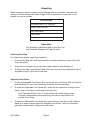
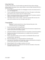
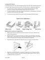
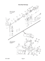
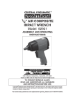
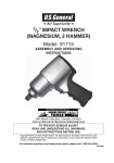
PLATE JOINER
4 INCH
38437
ASSEMBLY and OPERATING
INSTRUCTIONS
Distributed Exclusively by Harbor Freight Tools®
3491 Mission Oaks Blvd., Camarillo, CA 93011
Copyright © 1998 by Harbor Freight Tools. All rights reserved. No portion of this
manual or any artwork contained herein may be reproduced in any shape or
form without the express written consent of Harbor Freight Tools.
For technical questions and replacement parts, please call 1-800-444-3353
Specifications
Motor Speed
10,000 RPM (no load)
Power rating
120 VAC at 60 Hz, single phase, 6 A
Blade
4 inch diameter
Fence Adjustments
Max depth: 1-1/8 inches;
Max. angle: 45 degrees
Preset Depth Stops
0, 10, and 20
Power Cord
18 AWG, 3-prong plug
Save This Manual
You will need the manual for the safety warnings and precautions, assembly instructions,
operating and maintenance procedures, parts list and diagram. Keep your invoice with this
manual. Write the invoice number on the inside of the front cover. Keep the manual and
invoice in a safe and dry place for future reference.
Safety Warnings and Precautions
WARNING: When using tool, basic safety precautions should always be followed to reduce
the risk of personal injury and damage to equipment.
Read all instructions before using this tool!
1.
Keep work area clean. Cluttered areas invite injuries.
2.
Observe work area conditions. Do not use machines or power tools in damp or wet
locations. Don’t expose to rain. Keep work area well lighted. Do not use electrically
powered tools in the presence of flammable gases or liquids.
3.
Keep children away. Children must never be allowed in the work area. Do not let
them handle machines, tools, or extension cords.
4.
Store idle equipment. When not in use, tools must be stored in a dry location to
inhibit rust. Always lock up tools and keep out of reach of children.
5.
Do not force tool. It will do the job better and more safely at the rate for which it was
intended. Do not use inappropriate attachments in an attempt to exceed the tool
capacity.
6.
Use the right tool for the job. Do not attempt to force a small tool or attachment to
do the work of a larger industrial tool. Do not use a tool for a purpose for which it was
not intended.
7.
Dress properly. Do not wear loose clothing or jewelry as they can be caught in
moving parts. Protective, electrically non-conductive clothes and non-skid footwear
are recommended when working. Wear restrictive hair covering to contain long hair.
REV 07h
SKU 38437
Page 8.
Use eye and ear protection. Always wear ANSI approved impact safety goggles.
Wear a full face shield if you are producing metal filings or wood chips. Wear an ANSI
approved dust mask or respirator when working around metal, wood, and chemical
dusts and mists.
9.
Do not overreach. Keep proper footing and balance at all times. Do not reach over or
across running machines.
10. Maintain tools with care. Keep tools sharp and clean for better and safer
performance. Follow instructions for lubricating and changing accessories. Inspect tool
cords periodically and, if damaged, have them repaired by an authorized technician.
The handles must be kept clean, dry, and free from oil and grease at all times.
11. Disconnect power. Unplug charger when not in use.
12. Remove adjusting keys and wrenches. Check that keys and adjusting wrenches
are removed from the tool or machine work surface before plugging it in.
13. Avoid unintentional starting. Be sure the switch is in the Off position when not
in use and before plugging in. Do not carry any tool with your finger on the trigger,
whether it is plugged in or not.
14. Stay alert. Watch what you are doing, use common sense. Do not operate any tool
when you are tired.
15. Check for damaged parts. Before using any tool, any part that appears damaged
should be carefully checked to determine that it will operate properly and perform its
intended function. Check for alignment and binding of moving parts; any broken parts
or mounting fixtures; and any other condition that may affect proper operation. Any
part that is damaged should be properly repaired or replaced by a qualified technician.
Do not use the tool if any switch does not turn On and Off properly.
16. Guard against electric shock. Prevent body contact with grounded surfaces such as
pipes, radiators, ranges, and refrigerator enclosures.
17. Replacement parts and accessories. When servicing, use only identical
replacement parts. Use of any other parts will void the warranty. Only use accessories
intended for use with this tool. Approved accessories are available from Harbor Freight
Tools.
18. Secure Work. Use clamps or a vise to hold work. It is safer than using your hands and
it frees up both hands to operate the tool.
19. Do not operate tool if under the influence of alcohol or drugs. Read warning
labels on prescriptions to determine if your judgment or reflexes are impaired while
taking drugs. If there is any doubt, do not operate the tool.
SKU 38437
Page Unpacking
When unpacking, check to make sure the following parts are included. If any parts are
missing or broken, please call Harbor Freight Tools at the number on the cover of this
manual as soon as possible.
ACCESSORIES
Assorted biscuits: 0, 10, 20 gauge
Carbon motor brush set
4 mm Hex wrench
Arbor wrench
Glue bottle
Operation
Part Numbers Used Below Refer to the Parts List
and Assembly Drawings On Pages 8 and 9.
Attaching Dust Bag
For efficient dust pickup, empty bag frequently.
1.
To install Dust Bag (45), slide bag connector onto dust porthole on Joiner (43) until it
snaps into place.
2.
To remove, pull release tab on right side of bag connector and slide bag off.
3.
To empty Dust Bag, remove Bag Clamp (63) from power cord and slide plastic clip off
large end of bag. Do this over a trash can.
Adjusting Front Fence
1.
To remove Adjustable Front Fence (44), remove the two Lock Knobs (59) and slide the
retaining Bolts (57) out of the front fence assembly, and remove fence.
2.
To attach the Adjustable Front Fence (44), insert the two fence bolts through the two
holes in front of the fence, and through the Joiner (43).
Note: The lower holes in front of Joiner contain nuts which may be used
to fasten a fixed auxiliary fence accessory, but are not used with the Adjustable Front Fence.
3.
To reposition Adjustable Front Fence (44), loosen the two Lock Knobs (59), slide the
fence up or down to desired position. Retighten Lock Knobs. The front of the base
plate has a height scale to help position the fence.
SKU 38437
Page Setting Depth Stops
The Plate Joiner features a 3-position depth stop wheel with three notches indicating
different depths. For example, when using a #0 plate, rotate the Depth Adjusting Dial (48) to
the notch marked “0”.
1.
Pull the Depth Adjusting Dial (48) out to disengage and rotate to the desired notch (0,
10, or 20). Reengage Dial.
2.
Turn tool upside down and place Adjustable Front Fence (44) against a solid surface,
push forward on the tool until it stops and is held in position.
3.
Check to see where the indicator lines up on the depth scale. The indicator should be
slightly past the depth number selected (0, 10, or 20).
4.
If the indicator does not line up (step 3), rotate the Long Screw (46) one way or the
other until the indicator lines up on the depth scale (step 3).
Changing Blades
Warning: To prevent personal injury, always disconnect the power to the
tool before removing or installing blades.
1.
Disconnect power and turn tool upside down.
2.
Loosen screws (56) in Adjustable Front Fence (44) and lower fence to expose the two
screws that hold the base assembly together.
3.
Using the Hex Wrench, remove both screws from front section of Joiner (43) assembly.
4.
Place the Arbor Wrench (included accessory) on spindle and hold to prevent the
spindle from rotating.
5.
Place an adjustable wrench (or 24 mm wrench) on the Blade Bolt (62) and loosen
counterclockwise, removing bolt.
6.
Slide Cutting Blade (61) out, noting the direction of the blade teeth.
7.
Install the new Cutting Blade onto the bushing, making sure blade teeth are facing the
correct direction (see arrow on illustration, next page).
8.
Replace Blade Bolt (62) and tighten clockwise until secure.
9.
Reassemble Adjustable Front Fence (44) and lower fence assembly to Joiner base
assembly using the two screws.
SKU 38437
Page Locking On/Off Switch
The Plate Joiner Switch (35) is located under the Hold Covers (28 & 29). The black push button
on the left side of the cover locks the switch in the On position for long cutting operations.
1.
To turn the tool On without locking it, press and hold the Switch button in. When
pressure is released, the switch button snaps back to the Off position.
2.
To lock the Switch On, press and hold the Switch button in, and then press in the black
pushbutton on the left side of the handle.
3.
To unlock the Switch from the On position, press and release the Switch button.
Typical Joiner Applications
Miter Joints
T-Joints
Edge to Edge Cuts
Butt Joints
Marking Slot Locations for Standard Cuts
1.
Always begin with the Joiner base cutting into the end of the wood, rather than the
face as illustrated below.
2.
Mark the center of slot at a point as least 2-1/2 inches from outer edge of the board.
Allow at least 1 inch between slots in multiple plate applications for best results. Mark
all slots on both boards at the same time to assure proper alignment.
3.
Align center line on face plate with the pencil mark on wood as illustrated below.
4.
Grasp the tool with both hands, turn power On and push the tool forward smoothly.
When Joiner base assembly has butted completely against wood surface to be cut,
pull back and then turn power Off.
SKU 38437
Page Marking Slot Locations for Other Types of Cuts
When making preparations for cutting slots for T-butt, miter, edge-to-edge, leg and rail, and
square pattern joints, there are two important steps to ensure proper alignment of the joints.
1.
Align all boards as you want them to appear when finished, then mark the center line
for the slots on all boards at the same time.
2.
Set plate depth before making cuts.
Maintenance
1.
Disconnect tool power before cleaning.
2.
Wearing ANSI approved safety glasses, use compressed air to blow the tool clean.
3.
Do not insert pointed objects into holes in attempt to clean them out.
4.
Use a mild soap and clean, damp rag to clean tool.
Caution: Certain cleaning agents and solvents can damage plastic parts. Some of
these are: gasoline, carbon tetrachloride, chlorinated cleaning solvents, ammonia and
household detergents that contain ammonia.
SKU 38437
Page Parts List
Item
Description
Qty
Item
Description
Qty
1
Spindle
1
33
Name Plate
1
2
Straight Key 4 x 12
1
34
Tapping Screw
4
3
Circlips for Hole
1
35
Switch
1
4
Ball Bearing 80101
1
36
Cord Armor
1
5
Screw M4 x 14
4
37
Cord Clip
1
6
Washer M4
8
38
Tapping Screw
2
7
Packing Gland
1
39
Cord Assembly
1
8
Plate
2
40
Spring
1
9
Gear
1
41
Lock Pin
1
10
Spindle Ring
1
42
Washer
1
11
Spindle Sleeve
1
43
Joiner
1
12
Tapping Screw
4
44
Adjustable Front Fence
1
13
Gear Cover
1
45
Dust Bag
1
14
Nut M6
1
46
Long Screw
1
15
Washer M6
1
47
Spring
1
16
Pinion
1
48
Depth Adjusting Dial
1
17
Ball Bearing 80100
1
49
Square Nut
1
18
Clamp
1
50
L-shaped Guide
2
19
Armature Assembly
1
51
Bolt M6
2
20
Ball Bearing 80018
1
52
Washer M6
2
21
Hoop
1
53
Top Handle
1
22
Stator Assembly
1
54
Allen Screw M10
2
23
Carbon Brush
2
55
Square Nut
2
24
Spring
2
56
Screw
2
25
Brush Hold Assembly
1
57
Bolt
2
26
Rubber Gauge Washer
1
58
Plastic Sleeve
2
27
Housing Assembly
1
59
Lock Knob
2
28
Hold Cover
1
60
Spacer
2
29
Hold Cover
1
61
Cutting Blade
1
30
Tapping Screw
2
62
Blade Bolt
1
31
Washer M4
8
63
Bag Clamp
1
32
Wire Assembly
2
SKU 38437
Page Assembly Drawings
Motor Assembly
Part Numbers
1 to 42
Joiner Assembly
Part Numbers
43 to 63
SKU 38437
Page