1
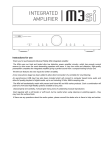
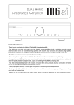
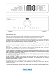
A1 Integrated
A1 SERIES CLASS A INTEGRATED AMPLIFIER WITH USB INPUT
INSTRUCTIONS FOR USE
Thank you for purchasing the Musical Fidelity A1 Integrated amplifier.
This new incarnation of the A1 Integrated uses a class A biased output stage to deliver the absolute best in
audio quality with no listener fatigue from crossover distortion artefacts. This results in an astounding
improvement in musicality and tonal neutrality.
The A1 is designed to be partnered with future A1 products, as well as our supercharger range. This offers a
financially lossless upgrade path. As a pure amplifier the A1 is almost perfect. The only limitation, due to
class A operation, is overall power. When you want to upgrade, the A1 is a perfect driver for the 550K or
750K superchargers, and was designed with this in mind. This combination yields one of the best
amplification systems available at any price.
Used properly and carefully, it should give many years of outstanding musical reproduction.
Dust regularly with a soft duster or soft brush, but be careful when using cleaning or polishing agents - they
may harm the surface finish.
If you have any questions about your audio system,
Please consult your dealer who is there to help and advise.
A1 Integrated
CONTENTS
PAGE
Section
3
Safety information
-
Mains plug (U.K. only)
Modification warning
4
General advice
-
Installation precautions
User information
5
Disposal information
6
Installation
-
Introduction
Cleaning
Installation
Audio connection
7
Facilities and connections
-
Illustrations – Main unit front & rear panels
8
Remote control
-
Operation and illustration
9
Amplifier operation
-
Starting, Volume, Mute, Phono, CD,
TUNER, AUX/HT, TAPE, Recording
Computer setup for USB (PC and MAC)
-
Basic amplifier fault finding
10
11
Amplifier problems?
12
Amplifier specifications
13
Manual history
Issue 2: 05th March 2008
EU disposal information
Page 2 of 13
A1 Integrated
SAFETY INFORMATION
IMPORTANT! (U.K. only)
This unit is supplied in the U.K. with mains lead fitted with a moulded 13 amp plug. If, for any reason, it is necessary
to remove the plug, please remove the fuse holder and dispose of the plug safely, out of reach of children.
It must not be plugged into a mains outlet.
The wires in the mains lead supplied with this appliance are coloured in accordance with the following code:
Green and yellow..............Earth
Blue................................Neutral
Brown.................................Live
WARNING - This appliance MUST be earthed
As the colours of the wires of the mains lead of this appliance may not correspond with the
coloured markings identifying the terminals in the plug, proceed as follows:
The wire which is coloured green-and-yellow must be connected to the terminal in the plug which is marked with the
letter E or coloured green or green-and-yellow, or by the earth symbol :
The wire which is coloured brown must be connected to the terminal which is marked with the letter L or coloured red.
The wire which is coloured blue must be connected to the terminal which is marked with the letter N or coloured black.
If connecting to a BS1363 plug, a 13 amp fuse must be used.
WARNING:
ANY MODIFICATIONS TO THIS PRODUCT NOT EXPRESSLY APPROVED
BY MUSICAL FIDELITY WHO IS THE PARTY RESPONSIBLE FOR
STANDARDS COMPLIANCE COULD VOID THE USER'S AUTHORITY TO
OPERATE THIS EQUIPMENT.
Issue 2: 05th March 2008
Page 3 of 13
A1 Integrated
GENERAL ADVICE
INSTALLATION PRECAUTIONS & USER INFORMATION
This new A1 is designed and built to provide trouble-free performance, but as with all electronic devices it is necessary
to observe a few precautions:
Heed all warnings shown on the back of the product.
Only connect the A1 to a mains outlet having the same voltage as marked at the back of the unit.
Always ensure that when disconnecting and reconnecting your audio equipment the mains supply is switched
off.
Position the mains lead and signal interconnects where they are not likely to be walked on or trapped by items
placed on them.
Do not use near water, or place water-filled containers on the A1, for example, a flower vase or potted plants.
If water does spill inside, immediately pull out the mains plug from the wall socket and inform your
dealer, who should then check the unit before further use. Entry of liquid into the A1 is dangerous, and
may cause electric shock or fire hazard.
Do not place the unit near direct heat sources such as radiators, direct sunlight or other equipment.
Do not remove any covers or try to gain access to the inside. There are no internal adjustments or fuses you
can replace yourself. Refer all service work to an authorised Musical Fidelity agent.
Note: Unauthorised opening of the equipment will invalidate any warranty claim.
Dust regularly with a soft cloth or soft brush but be careful when using cleaning or polishing agents - they may
harm the surface finish.
The electronics in modern hi-fi equipment is complex and may, therefore, be adversely affected or damaged by
lightning. For protection of the audio system during electrical storms, remove the mains plugs and disconnect any
aerial lead.
If after-sales service is required, to help the dealer identify the A1 please quote the serial number located on the rear
panel of the unit.
Issue 2: 05th March 2008
Page 4 of 13
A1 Integrated
DISPOSAL
The crossed out wheeled bin label that appears on the
back panel of the product indicates that the product must not be
disposed of as normal household waste. To prevent possible harm
to the environment please separate the product from other waste to
ensure that it can be recycled in an environmentally safe manner.
Please contact local government office or retailer for available
collection facilities.
DISPOSITION
La poubelle sur roulettes barrées X, qui apparaît en logo
sur le panneau arrière du produit, indique que celui-ci ne doit pas
être traité comme un déchet domestique commun. Afin de protéger
l'environnement, ce produit électronique devra être géré
séparément et donc recyclé selon les nouvelles normes
Européennes Rohs concernant les déchets d'appareils électroniques.
Prière de contacter les services concernés gouvernementaux ou
votre point de vente pour l'élimination et l'enlèvement de déchets
électroniques équipés de composants électroniques.
DISPOSAL
La etiqueta cruzada hacia fuera del compartimiento que
aparece en el panel trasero del producto indica que el producto no
se debe reciclarse como basura normal de la casa. Para prevenir
daños posible al ambiente separe por favor el producto de otras
basura para asegurarse de que puede ser reciclada de una manera
ambientalmente segura. Entre en contacto por favor a su oficina
gubernamental local o a su minorista para las instalaciones
disponibles de la colección.
RIFIUTI
L'etichetta del cassonetto barrato riportato sul retro
dell'apparecchio indica che il prodotto non deve essere smaltito
tramite la procedura normale di smaltimento dei rifiuti domestici.
Per evitare eventuali danni all'ambiente, separare questo prodotto
da altri rifiuti domestici in modo che possa venire riciclato in base
alle procedure di rispetto ambientale. Per maggiori dettagli
sulle aree di raccolta disponibili, contattate l'ufficio govenativo
locale od il rivenditore del prodotto.
FACHGERECHTE ENTSORGUNG:
Das auf der Geräterückseite angebrachte Label deutet
darauf hin, dass das Produkt nicht mit konventionellem
Hauskehricht entsorgt werden darf. Um Schäden und
Verschmutzungen an Umwelt und Mensch zu vermeiden, muss das
Produkt fachgerecht entsorgt und von anderem Abfall getrennt
werden. Wenden Sie sich bei Fragen hierzu an Ihren Fachhändler
oder an eine öffentliche Informationsstelle.
Issue 2: 05th March 2008
ITEM DISPOSAL INFORMATION
AFVAL
Het label op de achterzijde van dit apparaat, een
afvalbak op wielen met een kruis doorgehaald, geeft aan dat dit
apparaat niet samen met gewoon huishoudafval mag worden
weggegooid. Om mogelijke schade aan onze leefomgeving te
voorkomen dient dit apparaat, gescheiden van gewoon
huishoudelijk afval, te worden afgevoerd zodat het op een
milieuvriendelijke manier kan worden gerecycled. Neem voor
beschikbare inzamelplaatsen contact op met uw gemeentelijke
reinigingsdienst of met uw elektronica leverancier.
HÄVITTÄMINEN
Yliruksattua jäteastiaa kuvaava tarra tuotteen
takalevyssä kertoo, että tuotetta ei saa käsitellä normaalina
talousjätteenä. Ympäristön suojelemiseksi on tuote pidettävä
erillään muusta jätteestä ja se on kierrätettävä ekologisesti
kestävällä tavalla. Ota yhteyttä laitteen myyjään tai Pirkanmaan
Ympäristökeskukseen lähimmän kierrätyskeskuksen löytämiseksi.
AFSKAFNING
Logoet med en skraldespand med kryds over på bagsiden
af apparatet indikerer at dette produkt ikke må kasseres som normal
husholdningsaffald. For at forebygge mulig skade på miljøet, bedes
De separere dette produkt fra andet affald, og sikre at det bliver
genbrugt på en miljørigtig måde. Kontakt venligst de lokale
myndigheder eller din forhandler for oplysning om nærmeste
tilgængelige opsamlingssted for elektronikaffald.
∆ΙΑ∆ΙΚΑΣΙΑ ΑΠΟΡΡΙΨΗΣ
ΤΟ
ΣΗΜΑ
ΜΕ
ΤΟΝ
∆ΙΑΓΕΓΡΑΜΜΕΝΟ
ΤΡΟΧΗΛΑΤΟ ΚΑ∆Ο ΑΠΟΡΡΙΜΑΤΩΝ ΣΤΗΝ ΠΙΣΩ ΟΨΗ
ΤΟΥ ΜΗΧΑΝΗΜΑΤΟΣ
∆ΗΛΩΝΕΙ ΟΤΙ ΤΟ ΠΡΟΙΟΝ ΑΥΤΟ ∆ΕΝ ΠΡΕΠΕΙ ΝΑ
∆ΙΑΧΕΙΡΙΣΘΕΙ ΣΑΝ ΣΥΝΗΘΙΣΜΕΝΟ ΟΙΚΙΑΚΟ ΑΠΟΒΛΗΤΟ.
ΠΡΟΣ ΑΠΟΦΥΓΗ ΕΝ∆ΕΧΟΜΕΝΗΣ ΕΠΙΒΑΡΥΝΣΗΣ ΤΟΥ
ΠΕΡΙΒΑΛΛΟΝΤΟΣ, ΞΕΧΩΡΙΣΤΕ ΤΟ ΠΡΟΙΟΝ ΑΠΟ ΤΑ
ΑΛΛΑ
ΑΠΟΡΡΙΜΑΤΑ ΩΣΤΕ ΝΑ ΕΞΑΣΦΑΛΙΣΘΕΙ Η ΑΝΑΚΥΚΛΩΣΗ
ΤΟΥ ΜΕ ΤΟΝ ΠΡΕΠΟΝΤΑ ΤΡΟΠΟ.
ΠΑΡΑΚΑΛΟΥΜΕ ΝΑ ΕΠΙΚΟΙΝΩΝΗΣΕΤΕ ΜΕ ΤΗΝ ΤΟΠΙΚΗ
ΥΠΗΡΕΣΙΑ ΑΝΑΚΥΚΛΩΣΗΣ Η ΜΕ ΤΟ ΚΑΤΑΣΤΗΜΑ
ΑΓΟΡΑΣ ΓΙΑ ΠΕΡΙΣΣΟΤΕΡΕΣ ΛΕΠΤΟΜΕΡΕΙΕΣ.
Page 5 of 13
A1 Integrated
INTRODUCTION
Congratulations on the purchase of the new A1 Class A
Integrated amplifier. Great attention has been paid to internal
layout, isolating each circuit section to prevent possible
interaction.
The unit features a top quality USB input DAC to allow direct
connection to a PC or MAC for listening to MP3/WAV or
other digital music storage formats.
The preamplifier sections are our finely tuned and tweaked
preamplifier, for smooth sound coupled with low noise and
virtually no distortion. The preamp section includes a top
quality low noise phono stage which caters for MM cartridge
users.
The power amplifier consists of two class-A amplifier
modules with separate supplies for the absolute best in
separation and imaging. Generously rated, they are enough to
drive even the most demanding loudspeakers with ease. Low
distortion and very quiet they will deliver all music types
exactly as the artist originally intended.
The resultant performance achieved by this unit is among the
best in the world. It has excellent signal to noise ratio, low
distortion, wide bandwidth and dynamic range, with
extraordinary resolution and fine detail.
CLEANING
Before cleaning the unit, switch off power at the mains switch
and remove the mains plug from the wall socket.
Clean the cabinet and remote control unit using a moist cloth.
Using solvents, white spirit or thinners is not advised, as they
could damage the surface finish.
INSTALLATION
POWER CONNECTIONS
The A1 is supplied with a standard IEC mains cable which
plugs into the IEC socket at the back of the unit (see P.7)
AUDIO CONNECTIONS
Analogue Inputs: Connect all analogue sources to relevant
analogue inputs (see p.7 For more information). Use good
quality fully connected (signal and ground) coaxial phono
cables for all signal connections.
USB Input: Connect a USB A to B (not supplied) cable
between computer and USB input if required.
Please note: The USB input is a USB Digital to Analogue
Converter (DAC), not a “host controller”. It therefore does
NOT support direct streaming from USB players, media,
drives etc. It only functions with a personal computer/PDA
or equivalent attached.
Outputs: Connect loudspeakers to the terminals on the back
panel marked as LEFT and RIGHT SPEAKER outputs
The TAPE output allows loop through of analogue signals
for example, to pass on to recorder or monitor. It is also the
ideal output to connect our headphone amps into.
The PRE-OUT output allows analogue signals controlled by
the volume, to pass on to a second amplifier. This is useful
for bi-amping.
INSTALLATION
Position the A1 on a stable, horizontal surface where there is
no risk of it being knocked, or subjected to vibration such as
from loudspeakers.
Important note:
As a “CLASS A” amplifier, the unit dissipates a quantity of
power at all times, and it is important that it is adequately
ventilated. The sides are perforated to allow the smooth flow
of heat through the unit. It is therefore not recommended that
the unit is enclosed in a cabinet or placed where the ventilation
holes on the sides are impeded as this could result in the unit
cutting out due to excessive heat build-up.
The A1 must be protected from humidity - if the unit is
moved from a cold place to a warm room, leave the unit for an
hour or so to allow sufficient time for the moisture to
evaporate.
Issue 2: 05th March 2008
Page 6 of 13
A1 Integrated
FACILITIES AND CONNECTION
FRONT PANEL
1
2
3
4
1. ON/OFF Button
2. ANALOGUE, USB INPUT source selector buttons
3. DISPLAY
5
6
4. TAPE MONITOR button
5. VOLUME up/down
6. IR RECIEVER lens
REAR PANEL
7
7.
8.
9.
10.
8
9
USB Input (type ‘B’ socket)
PHONO INPUT RCA Sockets
PHONO GROUNDING 4mm post
AUX/HT input configuration switch
Issue 2: 05th March 2008
10
11
12
13
14
11. CD, TUNER, AUX/HT, TAPE INPUT RCA
Sockets
12. PRE, TAPE OUTPUT RCA sockets
13. LOUDSPEAKER OUTPUTS Left and right
14. IEC MAINS INPUT
Page 7 of 13
A1 Integrated
REMOTE CONTROL
Remote control Handset
The universal remote control shown below enables functions from this and related units to be operated from a convenient distance.
Equivalent buttons on the remote control have the same functions as those on the front panel of the unit. Other functions are only
available by remote control.
As the handset uses an invisible infra-red light beam, the front edge must be pointed directly towards the receiver window at the
front of the player, without visual obstruction between them.
If the range of the remote control greatly decreases, replace the batteries with new ones. Do not mix old and new batteries - two
are required, size AAA, LR03 or SUM-4.
Please dispose of used batteries in accordance to local regulations.
Tuner Buttons:
INFO – To access broadcast information
BAND – Selects DAB or FM
MENU – to choose options
STORE – Stores station as preset
AUTO TUNE – finds previous/next broadcast
SELECT – To choose preset/DAB station
MONO/STEREO – Option for weaker FM
stations
Amplifier Buttons:
PHONO – Selects Phono input
PRESET ↑ ↓ selects preset
TUNE ↑ ↓ steps up/down band
CD – Selects CD input
USB – Selects USB input
TUNER – Selects TUNER input
AUX/HT – Selects AUX/HT input
TAPE – Select TAPE input
VOLUME UP/DOWN – sets volume level
MUTE – Mutes speaker outputs until
pressed again
CD Buttons:
TIME – Displays Track Time/Time remaining
0-9 Buttons – Used to select track numbers
CHECK – Check pre programmed tracks
PROGRAM – Programs selection and order of
tracks
INTRO – Player plays first 10 seconds of each
track
REPEAT – Repeats whole disk or selected tracks
SEARCH – Fast forward/backward through track
STOP – Stop playing/Eject CD
CLEAR – Clears selected pre programmed
track
A/B Sets repeat start/end to repeat section
of track
SHUFFLE – Plays back tracks in random
order
TRACK – Next/previous track
PAUSE/PLAY – Stop/start CD playback
Issue 2: 05th March 2008
Page 8 of 13
A1 Integrated
AMPLIFIER OPERATION
STARTING
Once all connections are made, switch on the unit, using
the POWER button front of the unit. The backlit
display will light. The display will indicate the product
name will show but speaker outputs are muted, for about
fifteen seconds, so no sound will be heard from the
speakers.
A1
V0.0
MUTE
Once the 15 seconds is up the volume and selected
source input will indicate unit is settled, and ready for
use.
CD
™™™™
33
VOLUME
The volume should be adjusted for normal listening
levels. This is done by pressing the volume up/down
buttons on the front panel. The volume level is readily
identifiable on the display bargraph and numeric
indicator, in the above example it is set to 33% of the
full range.
Adjusting the volume can also be achieved using the
remote handset, using the volume up/down buttons (see
p. 9).
MUTE (remote only)
The sound from the speakers may be muted by use of
the MUTE button on the remote. Press once, and
MUTE will show in the display indicating muted state.
No sound will be heard from the speakers.
CD
MUTE
33
To return to listening; simply press the MUTE button
again so MUTE is no longer displayed.
USB
To use the USB input, connect computer USB output to
the USB socket (see p.7). Select USB input using the
source up/down buttons until USB is shown in the
display.
USB
™™™™
33
Selecting the USB input can also be achieved using the
corresponding button on the remote handset, (see p. 8).
PHONO
To use the phono (MM) input, connect turntable
cartridge outputs to the phono input RCA sockets (see
p.7). Select PHONO input using the source up/down
buttons until PHONO is shown in the display.
PHONO
™™™™
33
Selecting the PHONO input can also be achieved using
the corresponding button on the remote handset, (see p.
8).
CD
To use the CD input, connect CD player outputs to the
CD input RCA sockets (see p.7). Select CD input using
the source up/down buttons until CD is shown in the
display.
CD
™™™™
33
Selecting the CD input can also be achieved using the
corresponding button on the remote handset, (see p. 8).
TUNER
To use the tuner input, connect tuner outputs to the tuner
input RCA sockets (see p.7). Select TUNER input using
the source up/down buttons until TUNER is shown in
the display.
TUNER
™™™™
33
Selecting the TUNER input can also be achieved using
the corresponding button on the remote handset, (see p.
8).
AUX/HT
To use the AUX, as standard input, check the AUX/HT
switch (back panel) is set to AUX position. The display
will then refer to this input as AUX.
AUX
™™™™
33
Connect line outs from source to the AUX input (see
p.7). Select AUX input using the source up/down buttons
until AUX is shown in the display.
To use the AUX, as Home Theatre direct input, move
the AUX/HT switch to the HT position.
HT
™™™™
33
The display will then refer to the input as HT. Connect
Issue 2: 05th March 2008
Page 9 of 13
A1 Integrated
AMPLIFIER OPERATION
line level outputs from home theatre processor to the
AUX/HT input (see p.7). Volume control is now only
possible (for this input) on the external processor.
Please note connecting standard line signals to these
inputs in HT mode will cause very loud and damaging
signals at speakers that cannot be controlled through
the volume control. Please ensure correct AUX/HT
switch position before using this input.
Selecting the AUX/HT input can also be achieved using
the remote handset, using the corresponding button (see
p. 8), but AUX/HT switching is not available on the
remote.
TAPE
To use the TAPE input, connect external source to the
TAPE input (see p.7). Select TAPE input using the
source up/down buttons until TAPE is shown in the
display.
TAPE
™™™™
33
Selecting the TAPE input can also be achieved using
the corresponding button on the remote handset, (see p.
8).
RECORDING AND TAPE MONITOR
To record to tape, (or alternatively CD recorder, DAT,
minidisk or computer soundcard analogue input)
connect the tape out to the tape recorder line in. Press
the input selector button on the front panel or remote
control. This source will now be routed to the A1
TAPE OUT for recording by tape deck.
The recording can be directly monitored through the
loudspeakers by pressing the TAPE MONITOR
button. Press again to return back to the input being
recorded.
On some 3 head tape decks there is an additional
tape/source switch which should be in the tape position
for this to work. If in doubt, please consult tape deck
operating manual.
Note - adjustment of the volume control has no effect
on the recording level.
Computer setup for input USB input
A good quality USB A to B cable is required to connect
the unit to the computer.
Plug the B (square) end into the socket in the back of the
A1.
Plug the A (rectangle) end into a free USB socket on the
computer.
The computer should detect the new hardware and
install a generic driver automatically (No setup or driver
disk required).
CD, MP3, WAV files played on any software should
now play through the A1. This device has been designed
to work with PC Windows 98, ME, 2000, XP as well as
Apple Macintosh OS X.
Please note:
This device is a high speed serial data processor, and by
its nature, requires a very high volume of USB
bandwidth. It will benefit greatly from being the only
device connected on its USB ‘bus’. Sharing the same bus
with other devices may cause unwanted artefacts such as
dropouts or temporary loss of signal. This especially
includes the use of the A1 on a USB hub/splitter
alongside other USB components.
PC users
Check the computer has picked up the device and is
currently using it by clicking: (most Windows versions)
-
Start
Settings
Control panel
Sounds and Multimedia
Audio
Check that “USB audio device” appears under
PREFERRED AUDIO DEVICE tab
A second mixer will now be available which will be the
default mixer whenever the A1 is plugged in. Use this
mixer to select the source or adjust levels if required.
Mac users
Check the computer has picked up the device and is
currently using it by clicking: (MAC OS X)
-
System preferences
Hardware
Sound
Check that “USB audio DAC” is selected under the
OUTPUT tab.
If the computer’s warning sounds/chimes are to played
through the A1, make sure it is selected under the
SOUND EFFECTS tab too.
Note: USB may also be selected as an output in some
individual programs
Issue 2: 05th March 2008
Page 10 of 13
A1 Integrated
AMPLIFIER PROBLEMS?
Basic problem-solving with an amplifier is similar to troubleshooting other electrical or electronic equipment. Always check the most obvious possible causes first,
such as the following examples:
Problem
No power when POWER button is pressed
No sound
Probable Cause
Remedy
Mains power plug is not fully inserted into rear
socket
Plug in securely.
Unit overheated
Check unit’s ventilation holes are not obstructed and
allow unit to cool down. Check speaker/wiring for
short circuits before switching on again.
Mute function is still active
Press the MUTE button on the remote control to
cancel.
Wrong connections between input sources and the
unit
Check audio input lead connections
Check speaker cables
Speakers not connected, or incorrectly wired
Sound cut out and/or “Output Overload” displayed
Loose connection
Check speaker and input connections
Output overload or short circuit
Switch unit off. Check speaker connections for
shorting strands or wires. When all has been doublechecked reduce volume and switch unit back on.
N.B. Take great care when bi-wiring or bi-amping
that speaker bass and treble linking straps are
removed; see speaker manual for more information
Sound is not precise, lacking in bass and stereo
image
Hum
Speakers are connected out of phase, i.e.,
connections to one speaker (+ and -) are reversed
Ensure speakers are connected with same polarity at
amplifier and speaker ends.
Audio connector plug not fully pushed in
Insert plug securely
Cable Fault
Check cable is connected at both ends.
Unsuitable Cable
N.B. Some esoteric cables have internal wiring
intentionally disconnected/modified. For best results
on all inputs analogue AND digital, please use good
quality screened coax; signal and screens both
separately connected at both ends.
(e.g. cable grounds not connected)
No audio output, or too low level output
No audio output from USB input
Not detected when connected to USB
Incorrect or missing connections
Check connections and make sure they are secure.
USB Driver not selected (PC or MAC)
See P.9 PC users or MAC users section
USB Cable not connected
Check connections and make sure they are secure.
USB Driver not selected (PC or MAC)
See P.9 PC users or Mac users section
USB Cable faulty
Check and replace cable
USB not working/enabled on computer
Check USB port functions with another device.
Correct USB drivers not installed
Please check with the computer manufacturer.
Enquire about USB driver or update.
(can happen particularly with factory- preinstalled
Windows operating systems)
Dropouts in sound (USB input)
Shared USB port with another device
Computer busy with another application
Remote control does not work
Avoid sharing the USB port with other devices, if
possible.
Computer low on resources
At times an application (program) may intervene,
sometimes invisibly e.g. a virus scanner. When this
happens, computer resources are temporarily used
up, and playback may falter. This is not a fault. Try
running fewer applications if possible.
Amplifier’s POWER switch is set to off
Set switch to on
Unit overheated
Check for excessive heat build-up.
One or more batteries fitted the wrong way round
Insert batteries correctly
Batteries are flat
Change batteries for a new set
Remote control is not pointed directly towards the
front panel of the amplifier
Ensure there is no obstruction between the remote
control and amplifier front.
Interference from another source
Lighting such as fluorescent, incandescent, or even
sunlight contains large amounts of infra red
radiation. Ensure such sources are not shining
directly on the infra red window as this could
swamp the signal from the remote control.
Also check the system and any other nearby remotes
for stuck buttons
Remote control range has greatly reduced
Batteries are running out
Change batteries for a new set.
If none of these actions affect a cure, please contact the dealer, or an authorised Musical Fidelity service agent. Remember; never open the case of the A1, as this
will invalidate the guarantee.
Issue 2: 05th March 2008
Page 11 of 13
A1 Integrated
AMPLIFIER SPECIFICATIONS
Output:
Voltage, RMS
Voltage, Peak-to-peak
Power
Current peak-to-peak
Damping factor
Output devices per channel
Pre-out impedance
17V
48V
36W
22.8A
142
2
47 ohms
Line input:
THD + N, 20Hz to 20 kHz
Signal / noise ratio
Input sensitivity for full
power
Input impedance
Overload margin
Channel separation
Frequency response
<0.02%
-94dB A-wtd.
120mV
Phono input:
Cartridge type
Phono input response
Signal/noise ratio
Input sensitivity
Input impedance
Overload margin
Connections:
Line level inputs
Line level outputs
Digital inputs:
Speaker outputs:
43K ohms
37dB
>52dB
20Hz to 20kHz +0,-0.3dB
MM
RIAA/IEC combined,
see graph
-81dB A-wtd.
3.3mV
47K ohms
29dB
100 / 115 / 230Volts AC 50 /
60Hz (factory pre-set),
130W maximum
Accessories:
Mains lead
Remote control
Batteries
10 Amp IEC type
A1, universal
Size LR03 or
AAA, manganese
alkaline type
Dimensions:
Unit only
440mm
77mm
290mm
Unit in shipping carton
536mm
21 inches
200mm
7 ¾ inches
385mm
15 ¼ inches
1 5 .0
1 0 .0
PHONO
RES P O NS E
5 .0
dB
0 .0
R IA A
- 5 .0
P HO NO
- 1 0 .0
R I A A / I EC
- 1 5 .0
- 2 0 .0
2 0 .0
3 1 .5
5 0 .0
8 0 .0
125
200
315
500
1000
1600
2500
4000
6300
10000 16000
F r e q u e n c y (H z )
4 pairs line level RCA connectors
1 pair phono (moving magnet) level RCA connectors
1 pair RCA preamp line outputs (level controlled by volume)
1 pair RCA tape line outputs (fixed level)
1 USB 1.1 (32, 44, 48kHz sample rates) type B connection for computer/pda
1 pair 4mm banana plug/binding posts per channel
Power requirement:
17 ⅓ inches
3 inches
11 ½ inches
2 0 .0
1 off
1 off
2 off
wide
high inc. feet
deep inc. terminals
wide
high
deep
Weight:
7.15 kg
10.5 kg
15 ¾ lbs
23 lbs
Unboxed
In shipping carton,
with all accessories
Musical Fidelity reserves the right to make improvements which may result in specification or feature changes without notice.
Issue 2: 05th March 2008
Page 12 of 13
A1 Integrated
RELEASE
MANUAL REVISION
DATE
CHANGES
Issue 1
16th January 2008
1st issue
Issue 2
05th March 2008
Corrected front panel
buttons
Issue 2: 05th March 2008
Page 13 of 13