1
Super Zoom Master
L-608/L-608
Operating Manual
Blank page
Congratulations on your purchase of a
Sekonic Super Zoom Master L-608/L-608CINE
Exposure Meter.
The Super Zoom Master L-608/L-608CINE is the latest addition to the extensive
line of Sekonic Exposure Meters which have been market leaders.
It was designed to be the ultimate meter, a do-all instrument for the most demanding
pros.
It is the first zoom spot meter with digital spot viewfinder readout on the market.
Nine camera-quality lens elements are required to accomplish its 1° to 4° zoom
range.
its sealed housing and controls make it water and moisture resistant.
Yes, you can use it in the rain, but it is not an underwater meter.
The large LCD display makes reading easy, and it lights up automatically in dark
surroundings.
In order not to crowd the controls, four functions which are less frequently used,
are confined to DIP switches, located in the battery compartment.
Because of its many features, the L-608/L-608CINE requires this rather extensive
manual. But since you will never use all of the function at the same time, once you
have learned all about it, it is simple and its use will become second nature.
The Super Zoom Master L-608/L-608CINE has undergone extensive quality
controls at every step of manufacture. Please read this instruction manual
thoroughly, to be able to take advantage of its many features and to obtain the
long service life it is designed for.
Thank you for your confidence in Sekonic.
Table of Contents
1.
Parts Designation ................................................................................................................ 1
2.
Explanation of the Liquid Crystal Display (LCD) .................................................................. 2-3
3.
Before Using ........................................................................................................................ 4-6
1.
Attach the strap ......................................................................................................... 4
2.
Inserting the battery .................................................................................................. 4
3.
Checking battery capacity ......................................................................................... 4
4.
Replacing battery during measurement
or when using the memory function .......................................................................... 5
5.
Auto Power Off function ............................................................................................. 5
6.
Setting main ISO film speed ...................................................................................... 5
7.
Setting second ISO film speed (ISO 2) ..................................................................... 5
8.
Mesurement Lock and Measurement Lock Off .......................................................... 6
4.
Basic Operation ................................................................................................................... 7-12
1.
Incident or reflected spot measuring ......................................................................... 7
2.
Setting measuring mode ........................................................................................... 8
3.
Setting DIP switches .................................................................................................. 9
4.
When set for incident light ......................................................................................... 10
5.
When set for reflected light (spot metering) .............................................................. 11
5.
Measurment ........................................................................................................................ 13-22
1.
Measuring Ambient Light ........................................................................................... 13
1-1 Shutter Speed Priority mode ........................................................................... 13
1-2 Aperture Priority mode .................................................................................... 14
1-3 EV mode ......................................................................................................... 15
1-4 Cinematography .............................................................................................. 16
2.
Measuring Flash Light ............................................................................................... 18
2-1 Cord Flash mode ............................................................................................. 18
2-2 Auto Reset Cordless Flash mode ................................................................... 19
2-3 Cord Multiple Flash (cumulative) mode ........................................................... 21
2-4 Cordless Maltiple Flash (cumulative) mode .................................................... 22
6.
Advanced Functions ............................................................................................................ 24-35
1.
Memory function ........................................................................................................ 24
2.
Averaging function ..................................................................................................... 25
3.
Brightness Difference function ................................................................................... 25
4.
How to use an incident Illuminance (LUX or FC) Meter ............................................ 27
5.
How to use a reflected luminance (cd/m2 or FL) meter ............................................. 28
6.
How to use Exposure compensation function ........................................................... 29
7.
How to use Calibration compensation function ......................................................... 30
8.
Filter compensation ................................................................................................... 31
9.
Flash analyzing function ............................................................................................ 32
10. Custom setting function ............................................................................................. 33
11.
Wireless flash radio triggering system ....................................................................... 35
7.
Accessories ........................................................................................................................ 38-39
8.
Technical Data ..................................................................................................................... 40-41
9.
Safety Guide ........................................................................................................................ 42
10. Care and Maintenance ........................................................................................................ 43
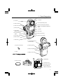
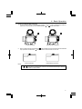
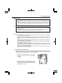
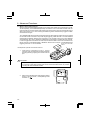
1. Parts Designation
q Lumisphere retracting ring
w Lumisphere
!4 Lock lever
e Liquid Crystal Display (LCD)
@6 Zoom Lens Ring
@4 Eyepiece (with Diopter Adjustment)
@7 Zoom Lens Protective Glass
O
SEK
r Average / ∆ EV (Brightness Difference)
button
NIC
u Memory button
t Jog Wheel
!3 Mini Light Receptor
Outlet
MEMORY
!2 Power button
(ON/OFF switch)
E
AV
PO
WE
V
/∆E
y ISO 2 button
R
ISO
ISO
1
M.C
MO
LE
2
AR
i Flash Synchro terminal
!1 ISO 1 button
!0 Mode set button
@5 Memory Clear button
DE
Su
per
L-6
Z
oom
Ma
ste
r
08
o Strap eyelet
@8 Incident/Reflected Spot
Selector Switch
@0 Synchro Terminal Cap
!5 Measuring button
!6 Battery Compartment Cover
@1 Strap
!7 Battery Cover Latch
!8 DIP Switches
@3 Zoom Lens Cap
@2 Connector cover
@9 1/4” Tripod Socket
RT-32 Radio transmitter
module compartment
!9 Battery Compartment
-1-
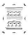
2. Explanation of the Liquid Crystal Display
!0 q
L-608
w
e
o
r
!1
i
t
u
L-608CINE
!0 q
i
w
e
o
r
!1
i
t
u
i
NOTE:
For explanation purposes, the display illustrated here shows all icons and readouts
simultaneously. Actual display will never show as above.
Auto Electro-Luminescent Display (EL)
• In low light (EV 3 or less), a green backlight will automatically illuminate the entire LCD. When using
the Mini Light Receptor or a Booster (optional accessories) the LCD will be illuminated after measuring,
regardless of the ambient light level.
• The LCD will not be automatically illuminated during measuring, in Cordless Flash mode or Wireless flash radio triggering mode.
• The Electro-luminescent backlight will automatically turn off 20 seconds after last operation.
-2-
2. Explanation of the Liquid Crystal Display
q
Measuring Mode Icons
Ambient (see page 13)
Auto-Reset Cordless Flash (see page 19)
Cord Flash (see page 18)
Wireless flash radio triggering mode (see page 35)
w
Incident / Reflected Spot Function Icons (see page 7)
Appears when in Incident mode
Appears when in Reflected Spot mode
e
ISO Display
Displays ISO film setting
Displays second ISO film setting when ISO 2 button is pressed
r
Flash Analyzing indicator
0 to 100% in 10% increments (percentage of the flash in the total exposure)
t
+/- Compensation Indicator
Appears when +/- Compensation is set
y
Digital aperture value, Aperture Priority, EV Brightness Difference, Average function, EV display
Appears when in Aperture Priority (f/stop) mode (see page 14)
Appears when using brightness difference function (See Page 25)
Appears when using Averaging function (see page 25)
Appears when using EV mode (see page 15)
u
Analog Scale
Displays marks at apertures or shutter speed indicating full or half stop values (608),or full or 1/3
stop values (608 CINE) for measurement, also displays memory and average values
Appears when below display range
Blinks when under exposed below measurement range
Appears when above display range
Blinks when over exposed above measurement range
i
Shutter priority indicator, shutter speed display for still photography or frames per second (f/s) for
cinematography
Appears when Shutter Priority (T) mode (see page 13)
Appears when shutter speed is in minutes
Appears when shutter speed is in full seconds
Appears when cine speed is set in frames per second (see page 16)
Appears when shutter angle is set to a value other than 180 degrees (608 CINE)(see
page 17)
o
Battery Power Indicator (see page 4)
!0
Memory / Multiple Flash Indicator Display
Appears when Multi (cumulative) flash measurement mode and shows the cumulated
number of measurements (see page 21)
Appears when reading is memorized and shows the number in memory (see page 24)
!1
Illumination mark/brightness mark
Appears when Foot-Candle is selected (608/608 CINE)
Appears when Lux is selected (608/608 CINE)
Appears when Foot-Lambert is selected (608 CINE)
Appears when Cd/m2 is selected (608 CINE)
-3-
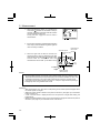
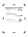
3. Before Using
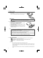
1.
Attach the strap
Attach the Strap @1 by passing the small end loop through the
eyelet o and passing the other end of strap through it.
E
OD
MO
Su
pe
rZ
L-
oo
m
60
M
as
te
r
8
WARNING
• Please place in a location where an infant cannot reach and accidentally get the strap
wrapped around his or her neck. There is danger of strangulation.
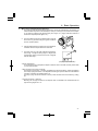
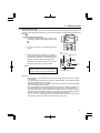
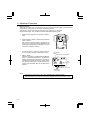
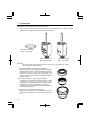
2.
Inserting the battery
1. Requires one 3.0 v CR123A lithium battery.
2. Open the Battery compartment cover latch !7, and remove the Battery compartment cover !6.
3. Insert the battery, observing the polarity with the +,- marks
in the battery chamber.
4. Align the tabs of the Battery compartment cover with the
notches in the back of the meter, and press down to close
the Battery cover latch.
NOTE:
• To prevent loss of All-weather seal, be careful that dirt does not get stuck on the rubber
seal and that the seal is not damaged.
• Remove battery if meter is not used for an extended period. Batteries can leak and
damage the exposure meter. Dispose of used batteries properly.
• If the LCD does not light, check that the battery capacity is sufficient, and check that the
battery positive and negative terminals are not reversed.
• The meter has a connector for a plug-in radio transmitter module. Do not remove the
connector cover unless you are installing the radio module, failure to do so could cause
the electronic circuit board to be exposed to damaging static electricity.
3.
Checking battery capacity
• When the Power button !2 is ON, the battery power indicator on the LCD is displayed.
(Displayed) Battery power level is good.
(Displayed) Battery power level is low. Have a spare battery ready.
(Blinking)
Replace battery immediately.
Reference:
• We recommend you always have a spare battery on hand.
• If the liquid crystal display extinguishes immediately after the display appears when
power is first applied, that is an indication that the battery is dead. Please promptly
replace the battery.
• A3 second pause between power on and off is recommended to avoid damage to the
meter.
-4-
3. Before Using
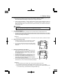
4.
Replacing battery during measurement or when using the memory function
1. Always turn the power OFF before replacing batteries. If batteries are removed with the power
ON, measurements and settings in memory can no longer be recalled.
2.
If after replacing the battery, or during measurements, strange screens (displays that have not
been set) appear in the LCD, or nothing happens, no matter what button is pushed, remove the
battery and wait at least ten seconds and then replace the battery. This allows the software to
automatically reset.
WARNING:
• Never place batteries in fire, short, disassemble, or heat them. The batteries might break
down, and cause an accident, injury or pollute the environment.
5.
Auto Power Off function
1. To conserve battery power, the meter will turn off about twenty minutes after last use.
2. Whether the Auto Power Saving feature turns the power off or the Power button !2 is pressed,
the settings and measured values remain stored in memory. When the Power button is pressed
again the last settings are displayed.
Reference:
• The power shuts off automatically after 1 minute when the power button is pressed and held.
6.
Setting main ISO film speed
1. Hold down the ISO1 button !1 and turn the Jog wheel
t to select ISO film speed for the film being used.
2.
You can also change the ISO film speed after taking
measurements. The new value is automatically
displayed.
ISO 1
7.
Setting second ISO film speed (ISO 2)
1. This feature is useful when using a second film with
different ISO film speed, using PolaroidTM proofing film,
or for exposure correction (when using a filter, closeup photography, etc.).
2. Hold down the ISO 2 button y and turn the Jog wheel
to select ISO film speed of the film being used.
3. Once this is set, after taking a measurement, the measured value for the second film speed will be displayed
when the ISO 2 button is pressed.
4. You can also change the second ISO film speed after taking
measurements. The new value is automatically displayed.
ISO 2
Reference:
• The following settings are possible when using custom setting function P33.
1. It is possible to set the Filter compensation within a range of ±5 EV in 1/10 steps.
2. Filter factor number compensation enables you to set seven types of filters frequently used
in the CINE industry. (Kodak Wratten Filters)(608 CINE only)
-5-
3. Before Using
8.
Mode and Setting Lock or Lock Off
1. Hold down the Mode set button !0 and ISO1 button !1
and "LOC" will appear to indicate that the Settings are
locked. The last measurement is held until the lock is
released, even if the Jog wheel t is accidentally
moved.
However, if the measurement button !5 is pressed, a
new measurement is displayed with the same locked
settings.
ISO 1
MODE
2. To release the Measurement lock, perform the same
operation for the Measurement lock, Hold down the
Mode set button and ISO1 button and "Off" will appear
to indicate that the Measurement lock is released.
ISO 1
MODE
Reference:
• If power to the meter is turned off or auto off is activated when in the locked position, the dial
lock function will continue operating when the meter is turned on again.
-6-
4. Basic Operation
1.
Incident or reflected spot measuring
1. To set for either incident or reflected light operation, turn the Incident / Reflected Spot Selector
Switch @8 on the eye piece, to the desired position ( or
mark) until it clicks.
Incident operation
2.
Reflected Spot operation
When incident operation is selected, the
mark will blink for three seconds and when Reflected
mark will blink for three seconds on the LCD.
Spot operation is selected the
Incident operation
Reflected Spot operation
NOTE:
• Before taking measurements, always make sure that the desired measurement mode
or ) is chosen by checking the LCD or that the Incident/Reflected Spot Selector
(
Switch is clicked in proper position.
-7-
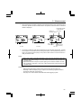
4. Basic Operation
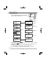
2.
Setting measuring mode
1.
Hold down the Mode set button !0 and turn the Set/change
dial t to select the desired mode. The mode switching
sequence is shown in the chart below:
MODE
Shutter Speed Priority mode
(Ambient light)
Wireless Multiple Flash
Radio Triggering mode
See page 13
See page 37
Dip switch 2
Wireless Flash Radio
Triggering mode
with Radio
transmitter module
Aperture Priority mode
(Ambient light)
See page 14
with Radio
transmitter module
See page 37
EV mode (Ambient light)
See page 15
Dip switch 1
Wireless Flash Sub/channel
Setting mode
with Radio
transmitter module
See page 35
LUX, FC
FL, Cd/m2 → CINE only
See page 27,28
Cord Multiple Flash
(Cumulative) mode
Auto Reset Cordless Flash
mode
See page 21
Dip switch 2
See page 19
Cordless Multiple Flash
(Cumulative) mode
See page 22
Cord Flash mode
See page 18
Dip switch 2
can only be selected when the respective DIP switch
•
Modes enclosed in dotted lines
is in ON position (see page 8).
•
Modes enclosed in
lines can only be selected when Optional Radio Transmitter Module is installed.
Each mode can be selected to display or not with custom setting.(See page 33)
FC or LUX (Illuminance) can be displayed in incident light mode.
FL or Cd/m2 (Luminance) can be displayed in reflected light mode. (608 CINE only)
•
•
•
Reference:
• Ambient light is continuous light like natural light (sunlight), fluorescent lamps or tungsten lamps.
• Flash light is a brief, intense burst of light made by such as electronic flash units or flash bulbs.
-8-
4. Basic Operation
3.
Setting DIP Switches
1. Switches for setting modes that are used infrequently are housed in the Battery compartment
of the meter. Select the mode you want prior to beginning measurements.
2.
The DIP switches can be set by sliding the DIP switch !8 for the mode you want to select in the
ON position.
*
EV settings
When DIP switch 1 is turned on, EV exposure readings are possible. (ambient light)
*
Multi settings
When DIP switch 2 is turned on, multiple flash cumulative mode is possible.
*
Buzzer setting
When DIP switch 3 is on, the buzzer sounds when light from a flash is received in the cordless
mode.
*
CS setting (custom settings)
When DIP switch 4 is on, the mode changes to the custom setting mode, thereby enabling
various settings (refer to P33).
1
2
3
4
-9-
4. Basic Operation
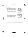
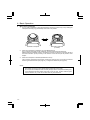
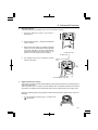
4.
When set for incident light
1. You can select extended or retracted lumisphere measuring positions by firmly rotating the
lumisphere retracting ring (UP/DOWN) until it clicks into position.
Extended Lumisphere
Retracted Lumisphere
(Lumidisc)
2.
When the Lumisphere is extended. (3-D Light Measurement)
This is used to photograph people, buildings, and other three dimensional objects.
Measurements are basically made by the method of measuring with the lumisphere aimed in
the camera direction (more precisely, in the direction of the lens axis) at the position of the
subject.
3.
When the Lumisphere is retracted (flat diffuser function)
This is used to photograph manuscripts, paintings or other flat copy. It can also be used for
measuring illumination levels (see page 27), or brightness difference (see page 25).
NOTE:
• If the device is used with the Lumisphere retracting ring in a middle position, distributed
light quality will change, and suitable measurements cannot be made.
• Do not push the Lumisphere down manually. Always use the Lumisphere retracting ring.
• If the lumisphere becomes soiled, wipe it with a soft, dry cloth. Organic solutions (paint
thinner, benzene, etc.) must not be used under any circumstances.
-10-
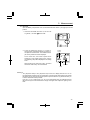
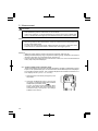
4. Basic Operation
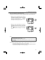
The black circle A in the finder indicates the measurement range. The light receiving angle is 1 degree with
the telephoto setting of the zoom lens and 4 degrees
with the wide angle.
C
4.
Memory
Take the measurement by aligning the circle inside the
viewfinder with the subject area to be measured.
S
4° 3.
M SPO
1~
The spot metering area can be selected by turning the
Zoom Lens ring @6 while looking through the viewfinder
from the camera position.
T
2.
ZOO
When set for reflected light (spot metering)
1. This method measures the brightness (luminance) of the light reflected from the subject. It is
useful for distant objects such as landscapes, when you cannot go to the position of the subject,
or for metering subjects that generate light (neon signs, etc.), highly reflective surfaces or
translucent subjects (stained glass, etc.).
EKON
I
5.
A
(Display in spot viewfinder)
< Diopter Adjustment >
Turn the eyepiece @4 and adjust the diopter so that the circle in the finder is clearly visible when
you look into the finder.
< Step-Up Ring (Lens Hood)> (optional)
The step-up ring (30.5mm → 40.5mm), available as an optional accessory, makes it possible to
mount step-up rings and filters. This simplifies the setting of exposure without the troublesome
correction calculation of polarizing filters, etc.
The step-up ring can also be used as a hood to protect the zoom lens from scratching, soiling,
etc.
< 2x Angle Converter > (optional)
Mounting the 2x angle converter to the objective lens unit enables zoom measurements at a
light receiving angle of 2° - 8°.
-11-
4. Basic Operation
< Lumigrid > (optional) (Receiving Angle 54°)
1. Remove the Lumisphere
The lumisphere unit is removed by holding both the
upper and lower sections of Lumisphere retracting
ring q and turning it counterclockwise while pushing
the Lock lever downward.
2.
Mount the lumigrid
To mount Lumigrid, align the mount/removal indicator
mark and then clockwise
on the Lumigrid with the
direction to secure it in place.
3.
Take measurements by aiming the lumigrid precisely at the area of the subject to be measured
from the position or direction of the camera.
4.
Follow the same procedure to mount the lumisphere.
CAUTION:
• Be sure to avoid touching the light receiving sensor when mounting or removing the lumisphere
or lumigrid. In case of touching it, clean with soft dry cloth.
-12-
5. Measurement
1.
Measuring ambient light
In this measurement mode, we have the choice of shutter priority mode, aperture priority mode and
EV mode. Hold down the Mode set button !0 and turn the Jog wheel t to select ambient measurement
mode .
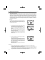
1-1 Shutter Speed Priority mode
1. Hold down the Mode set button !0 and turn the
Jog wheel to select Shutter Speed Priority mode
.
POWER
2.
Turn the Jog wheel to set the desired shutter
speed.
3.
Press the Measuring button ! 5 to make a
measurement. Release the Measuring button to
complete the measurement. The measured value
(aperture value) at that time will be displayed.
AVE./∆EV
ISO 1
ISO 2
MODE
MEMORY
Set
shutter speed Measured f stop
value
While pressing the Measuring button, the meter
measures continuously until it is released.
1/10
f stop
NOTE:
• The LCD panel displays 1/10 stop only when
either increments of shutter speed or
aperture is set full stop with custom settings.
Measured f stop
Reference:
• It is possible to switch between full, 1/2 and 1/3 shutter speeds with custom settings
(see page 33).
• You can set shutter speeds from 30 minutes to 1/8000 seconds. After 1/8000 the shutter
speeds of 1/200 and 1/400 can be set.
• After measurement, the F stop value corresponding to the shutter speed is displayed
when the shutter speed is changed.
• The L-608 displays the measured aperture value in either full or half stop increments on
the analog scale, while L-608 CINE displays it in either full or 1/3 stop increments.
• “E.u” (Exposure under) or “E.o” (Exposure over) appears when the combination of shutter
speed and aperture is outside the display range. Changing the shutter speed or aperture
with the Jog wheel will allow you to find a combination that is possible.
• If the “E.u” or “E.o” readout blinks, this indicates that the light level is beyond the
measurement range of the light meter. Adjust lighting in this case.
-13-
5. Measurement
1-2
Aperture Priority mode
1. Hold down the Mode set button !0 and turn the Jog wheel
to select aperture priority mode .
2. Turn the Jog wheel t to set the desired f stop
value.
MODE
Measured value
(shutter speed)
3. Press the Measuring button !5 to make a
measurement.
Release the Measuring button to complete the
measurement. The measured value (shutter
speed) at the time will be displayed.
Set f stop value
1/10
shutter
speed
While pressing the Measuring button, the
meter measures continuously until it is
released.
Measured shutter speed
Reference:
• It is possible to switch between full, 1/2 or 1/3 F stop values with custom settings.
• You can set aperture from 0.5 to F161. Please note that in 1/3 stop increments F0.56 is
and F0.63 is displayed as .
displayed as
• The L-608 displays the measured aperture value in either full or half stop increments on
the analog scale, while L-608 CINE displays it in either full or 1/3 stop increments.
• Readings outside the display range or beyond the measuring range are similar to the
previous instruction (see page 13).
• After measurement, the shutter speed corresponding to the F stop is displayed when the
F stop is changed.
-14-
5. Measurement
1-3 EV mode
Open the Battery compartment cover !6 and slide the EV DIP switch 1 (see page 9) to the ON
position.
1. Hold down the Mode set button !0 and turn the
value mode.
Jog wheel t to select
MODE
2. Press the Measuring button ! 5 to make a
measurement. Release the Measuring button to
complete the measurement. The measured value
(EV value) at that time will be displayed.
Shutter
speed
At the same time, the shutter speed will be
displayed in the digital display area, and the
corresponding f stop will be displayed on the analog
scale.
While pressing the measuring button, the meter
measures continuously until it is released.
EV value
f stop
Reference:
• “E.u” (Exposure under) or “E.o” (Exposure over) on the T or F display area and “U”or “O” on
the analogscale appears when the combination of shutter speed and aperture are outside
the display range. Changing the shutter speed or aperture with the Jog wheel will allow you
to find a combination that is possible.
If the “E.u” or “E.o” readout and “U”or “O” on the analogscale blink, this indicates that the
light level is beyond of the measurement range of the light meter. Adjust the lighting in this
case.
-15-
5. Measurement
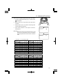
1-4
Cinematography
1. Hold down the Mode set button !0 and turn the Jog wheel
t to select ambient light shutter speed priority mode
.
MODE
2. Turn the Jog wheel to select the Cine Speed for the
camera that will be used.
Cine Speed are displayed after 1/8000, 1/200, 1/400 and
the unit is in frames per second (f/s).
[L-608]
The following Cine Speeds will display: 2, 3, 4, 6, 8, 12,
16, 18, 24, 25, 30, 32, 36, 40, 48, 50, 60, 64, 72, 96,
120, 128, 150, 200, 240, 256, 300 and 360 f/s.
[L-608CINE]
The following Cine Speeds will display: 1, 2, 3, 4, 6, 8,
12, 16, 18, 24, 25, 30, 32, 36, 40, 48, 50, 60, 64, 72, 75,
90, 96, 100, 120, 125, 128, 150, 200, 240, 250, 256,
300, 360, 375, 500, 625, 750 and 1000 f/s.
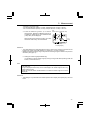
3. The shutter angle that these speeds are based on, is
180 degrees. For other angles make the following ISO
film speed corrections (L-608 only).
-16-
Shutter angle
Amount of ISO film
speed correction
160 degrees
-1/3
220 degrees
+1/3
MODE
5. Measurement
* Example of correction value
-1/3: Decrease ISO film speed by 1/3 stop, example: ISO 80 -1/3 stop = ISO 64
+1/3: Increase ISO film speed by 1/3 stop, example: ISO 80 +1/3 stop = ISO 100
Set
Measured f stop
4. Press the Measuring button ! 5 to make a shutter speed value
measurement. Release the Measuring button to
complete the measurement. The measured value
(f stop value) will be displayed.
While pressing the measuring button, the meter
measures continuously until it is released.
1/10
f stop
Measured f stop
on analog display
Reference:
• The L-608 displays the measured aperture value in either full or half stop increments on the
analog scale, while L-608 CINE displays it in either full or 1/3 stop increments.
• Readings outside the display range or beyond the measuring range are similar to the previous
instruction (see page 13).
5. Setting the shutter angle (608 CINE only).
It is possible to set the shutter angle by turning the Jog wheel while pressing mode set
button !0 and ISO2 button y .
Note:
• Shutter angle: The angle can be set in the range of 5° - 270° (in 5° steps) as well as
144° and 172°.
• "Ang" is displayed continuously on the LCD display if the shutter angle is set to any
value other than 180°.
• Press the mode set button and ISO2 button to confirm the shutter angle since it is not
displayed.
Reference:
• This setting is only valid when the shutter speed is set to display cine speed (f/s) in the cine
mode.
-17-
5. Measurement
2.
Measuring flash light
This method of measurement can be done in the following modes; with cord, without cord, multiple
flash with cord, multiple flash without cord and Wireless flash radio triggering mode (with optional
radio transmitter module). When Measuring flash light, the shutter speed and F stop value (value
combining ambient light and flash light: total amount of light) are displayed. The ambient light and
flash light are each displayed as separate values together with the total amount of light on the
analog scale. In addition, the ratio of flash light to the total amount of light is displayed at that time as
a value in 10% steps.The flash reading is displayed as a blinking mark above the analog scale. (See
page 32 for details)
2-1
Cord Flash mode
Connect the meter to the flash with a synchronization cord. Be sure to replace Synchro terminal cap @0 after your measurement.
1. Connect the flash synchro cord to the Synchro
terminal i on the exposure meter.
E
AV
PO
WE
EV
./∆
OR
IS
R
IS
ME
O1
MO
MO
RY
E
OD
R
TE
AS
M
8
60
L-
OM
ZO
2. Hold down the Mode set button !0 and turn the
Jog wheel t to select cord flash mode .
3. Turn the Jog wheel to set shutter speed. When setting shutter speed, first check the settings to confirm that they correspond to the settings on the camera.
MODE
Percentage of
flash in total
exposure
4. Press the Measuring button !5 to trigger the flash.
The measured value (f stop value) will be displayed.
Set
shutter speed
Measured f stop
value
1/10
f stop
Ambient
Flash
-18-
Measured f stop value
(total exposure)
5. Measurement
CAUTION:
• There is danger of electric shock if the meter is handled with wet hands, during rain, in
areas splashed by water or where there is a lot of moisture, if you use cord synchronized
flash.
• Under such conditions, it is recommended that you use the meter in the cordless flash
mode or Wireless flash radio triggering mode, and keep the Synchro terminal cap in
place.
NOTE:
• The electronic flash unit may trigger when you connect the Synchro cord or operate the
POWER Switch.
• Triggering voltage is 2.0 to 400 volts. For below 2.0V, trigger flash with the cordless
flash mode or wireless flash radio triggering mode, not synchro cord.
Reference:
• It is possible to switch the shutter speed between full, 1/2 and 1/3 stops by custom setting
of the DIP switch 4 (refer to P33).
• The shutter speed can be set from 30 minutes to 1/1000 of a second. After 1/1000 sec, the
meter can be set at the following intermediate speeds: 1/75, 1/80,1/90, 1/100, 1/200, or
1/400.
• If the film speed is changed after the measurement is taken, the new converted measured
value (f stop value) will be displayed.
• After measurement, the F stop value corresponding to the shutter speed is displayed
when the shutter speed is changed.
• “E.u” (Exposure under) or “E.o” (Exposure over) appears when the combination of shutter
speed and aperture are outside the display range. Change the shutter speed with the Jog
wheel and take measurements again.
• If the “E.u” or “E.o” readout blinks, this indicates that the light level is beyond the
measurement range of the light meter.
2-2 Auto-reset cordless flash mode
Measurements are made by the meter receiving the light from the flash. This measurement
mode is used when the Synchro cord will not reach because of the distance between the flash
and meter or when use of the Synchro cord is inconvenient.
1. Hold down the Mode set button !0 and turn the
Jog wheel t to set Auto-reset Cordless Flash
.
mode
2. Turn the Jog wheel to set shutter speed. When
setting shutter speed, first check the settings to
confirm that they correspond to the settings
available on the camera.
MODE
-19-
5. Measurement
3. When the Measuring button !5 is pressed, the
mode mark
will blink and the meter is ready to
measure. The ready to measure mode will continue
for approximately 90 seconds.
During this time, trigger the flash to make a
measurement.
4. If the 90 second period is exceeded and the blinking
mark stops, press the Measuring button again to
return to ready to measure.
Set shutter speed
5. When the light from the flash is received, the
measured value (f stop) is displayed. Even after
continues to blink
measurement, the mode mark
and the meter is in ready state and a new
measurement can be made. (Auto-reset function)
Perecentage of
flash in total
exposure
Measured f stop
value
1/10
f stop
Ambient
Flash
Measured f stop
(total exposure)
NOTES:
• When firing a flash, if the flash brightness is low compared to the ambient light, the meter
may fail to detect the light. In this case, make measurements using the cord flash mode.
• Rapid start fluorescent lamps and special lighting are sometimes mistaken for flash, and
accidentally measured. In this case, make measurements using the cord flash mode.
• The meter’s tripod socket permits mounting it to a tripod or light stand and placing it
strategically when using cordless flash mode.
Reference:
• After measurement, the F stop value corresponding to the shutter speed is displayed when
the shutter speed is changed.
• Setting the shutter speed is similar to the previous instruction. (see page 18) of "Cord flash
mode" of section 2-1.
• A new converted value is displayed when the film speed is changed after taking the
measurement.
• Readings outside the display range or beyond the measuring range are similar to the previous
instruction. (see page 19) of "Cord Flash mode" of section 2-1.
-20-
5. Measurement
2-3 Cord multiple flash (cumulative) mode
These measurements are used when the light generated by the flash is inadequate for proper
exposure. The repeated flash pops can be accumulated until the desired aperture is displayed.
The cumulative number is infinite. Only one digit is displayed if the cumulative number is ten or
more. Display returns 0 (0=10, 1=11, 2=12, etc.)
1. Slide DIP switch 2 to MULTI (see page 9) to the
ON position.
Hold down the Mode set button !0 and turn the
Jog wheel t to select cord multiple flash (cumu.
lative) mode
MODE
2. Turn the Jog wheel t to set shutter speed. When setting shutter speed, first check the
settings to confirm that they correspond to the settings available on the camera.
3. Connect the Flash synchro cord to the meter's
synchro terminal i.
4. Press the Measuring button !5 to trigger a flash. The measured f stop value at that time will
be displayed. Each time this is repeated, the accumulated f stop value and the number of
cumulative flashes is displayed.
Perecentage of flash
in total exposure
1/10 f stop
Number of
cumulative flashes
Set
shutter speed
1st. time
2nd. time
Measured f stop
(total exposure)
3rd. time
5. To clear the cumulative value, press M. CLEAR button @5 or switch to another mode by
turning the Jog wheel while pressing the mode set button.
-21-
5. Measurement
CAUTION:
• There is danger of electric shock if the meter is handled with wet hands, during rain, in
areas splashed by water or where there is a lot of moisture.
Under such conditions, it is recommended that you use the meter in the cordless flash
mode, or wireless flash radio triggering mode and keep the Synchro terminal cap in place.
NOTE:
• The flash unit may flash when you connect the synchro cord or operate the POWER switch.
• When firing a flash to take measurements, check the camera's synchronizing range and
set the proper shutter speed.
• For flash units with low electric trigger voltage, the flash may not fire. In this case, make
measurements in cordless flash mode or wireless flash radio triggering mode.
Reference:
• Setting the shutter speed is similar to the previous instruction (see page 18).
• Readings outside the display range or beyond the measuring range, are similar to the previous
instruction (see page 19) of "Cord flash mode" of section 2-1.
• If the film speed is changed after the measurement is taken, the new converted measured
value (f stop value) will be displayed.
2-4
Cordless multiple flash (cumulative) mode
These measurements are used when the light generated by the flash is inadequate for proper
exposure. The repeated flash pops can be accumulated until the desired aperture is displayed.
The cumulative number is infinite. Only one digit is displayed if the cumulative number is ten or
more. Display returns 0 (0=10, 1=11, 2=12 etc.)
1. Slide DIP switch 2 to MULTI (see page 9) to the
ON position.
2. Hold down the Mode set button !0 and turn the
Jog wheel t to select flash measurement cordless
.
multiple flash (cumulative) mode
Turn the Jog wheel to set shutter speed. When
setting shutter speed, first check the settings to
confirm that they correspond to the settings
available on the camera.
-22-
MODE
5. Measurement
3. When the light from the flash is received, the measured value (f stop) is displayed. Each
time this is repeated, the accumulated value for the aperture and the number of cumulative
flashes is displayed.
Perecentage of flash
in total exposure
1/10 f stop
Number of
cumulative flashes
Set
shutter speed
1st. time
2nd. time
Measured f stop
(total exposure)
3rd. time
4. The ready to measure mode will be displayed for approximately 90 seconds. If the 90
second period is exceeded and the blinking mark stops, press the Measuring button !5
again. The measured value (f stop) of the previous time reverts to 0 and the meter is in
ready to measure mode.
NOTE:
• When firing a flash, if the flash brightness is 9 EV lower than the ambient light, the
meter may fail to detect the light. In this case, make measurements using the flash with
cord flash mode.
• Rapid start fluorescent lamps and special lighting are sometimes mistaken for flash,
and accidentally measured. In this case, make measurements using the flash with
cord flash mode.
Reference:
• Setting the shutter speed is similar to the previous instruction (see page 18).
• Readings outside the display range or beyond the measuring range are similar to
the previous instruction. (See page 13)
• See page 35 for further details of Wireless flash radio triggering system.
-23-
6. Advanced Functions
1.
Memory function
This meter can store up to nine measured values in memory for incident light and reflected light
independently. This feature can be used in the following modes;
Ambient light : shutter speed priority, aperture priority (L-608 only) or EV mode.
Electronic Flash light : cord, cordless or wireless flash radio triggering mode.
1.
Press the Measuring button !5 and take a measurement.
2.
Press the Memory button u and store the measured
value in memory.
The number of values in memory is displayed on
the LCD. The memorized value is displayed on the
analog scale. By repeating this operation, up to nine
values can be stored in memory.
3.
To clear the memory, press the memory clear button @5 or switch to another measurement mode.
4.
Memory Recall
When the Jog wheel t is rotated while both Memory
button u and the Mode set button !0 are held down
together, the measured value stored in the memory
is displayed along with the memory number. When
any previous stored value is recalled with the exception of the last stored value, the “M” and number
will blink.
MEMORY
Set shuttter
speed
Number of memorized value
1/10
f stop
Measured f stop value
Memoreized
f stop values
NOTE:
• The memory function cannot be used in "Multiple flash cumulative mode."
• Measured values for ten times and over will be displayed but cannot be stored in memory.
-24-
6. Advanced Functions
2.
Averaging function
This function displays the average of up to nine of the values in memory.
1.
Press the Measuring button ! 5 and take a
measurement.
2.
Press the Memory button u and store the measured
value in memory.
3.
When the Ave/ ∆ EV button r is pressed, an average
value for up to nine measurements will be displayed
on the LCD. The value in memory and the average
values are displayed on the analog scale. An "A"
appears in LCD to indicate this is an average.
MEMORY
Averaging indicator
Averaged f stop
4.
The average mode can be canceled by pressing
the Ave/ ∆ EV button.
Number of memorized
value
1/10
f stop
AVE./∆EV
Averaged f stop
Set shutter speed
3.
Memorized
f stop value
Brightness difference function
This function is useful for evaluating studio lighting and checking the evenness of the lighting set-up
across the subject area.
Take a measured value at a certain point as a standard value. The difference between the standard
value and a new measured value is displayed as EV and the measurements on the analog scale.
Example of adjusting lights using brightness measurement with shutter speed priority mode (incident light).
1.
Turn the Lumisphere retracting ring q to lower it to the
mark position.
-25-
6. Advanced Functions
2.
Turn any secondary light source off. Point the
Lumisphere toward the main light source, from the
position of the subject and take a measurement. Press
the Memory button u and store the value in memory.
3.
Press the Average/ ∆ EV button r and display the "A"
mark on the LCD indicating a standard value.
AVE./∆EV
MEMORY
Now on reading
Set shutter speed
Difference
in EV
4.
Turn the main lighting off. Now, point the Lumisphere
toward the secondary light source. While the Measuring
button !5 is depressed and held down, the indicated
difference between the main and auxiliary light sources
is displayed in EV values. At the same time, the
standard value and a new measured value are
displayed on the analog scale.
AVE./∆EV
Memorized
f stop value
f stop value
being measured
EV difference of ∆ EV value
1
1.5
2
3
4
5.
Contrast ratio
2:1
3:1
4:1
8:1
16 : 1
Standard value can be cleared by pressing the Memory clear button, or Ave./ ∆ EV button.
Reference:
• To determine exposure after adjusting lights, turn both main and secondary light sources
on, raise the Lumisphere to the
mark position, then take a reading along the camera
light axis in incident light.
• This function can also be used for reflected light.
-26-
6. Advanced Functions
4.
How to use an incident illuminance (LUX or FC) meter
1.
Turn the Lumisphere retracting ring q to lower it to the
mark position.
2.
Make sure that any compensation (see page 29) is
canceled.
3.
Set the meter to LUX or FC mode for incident light with
custom setting (see page 33).
4.
Place meter parallel to the subject and take a
measurement.
Reference:
• Setting the meter to EV mode (DIP switch 1) and
ISO 100, the measured EV can be converted to
find the brightness level with the below conversion
table.
* EV value → Lux conversion table
Decimal places
EV
-2
-1
0
1
2
3
4
5
6
7
8
Decimal places
0
0.5
0.63
1.3
2.5
5.0
10
20
40
80
160
320
640
0.88
1.8
3.5
7.1
14
28
57
110
230
450
910
EV
0
9
10
11
12
13
14
15
16
17
18
19
0.5
1800
3600
7200
14000
29000
58000
120000
230000
460000
930000
1900000
* EV value → Foot candle (FC) conversion table
Decimal places
Decimal places
EV
-2
-1
0
1
2
3
4
5
6
7
8
0
0.5
0.06
0.12
0.23
0.46
0.93
1.9
3.7
7.4
15
30
59
0.08
0.16
0.33
0.66
1.3
2.6
5.3
11
21
42
84
EV
9
10
11
12
13
14
15
16
17
18
19
0
120
240
480
950
1900
3800
7600
15000
30000
61000
120000
0.5
170
340
670
1300
2700
5400
11000
22000
43000
86000
170000
-27-
6. Advanced Functions
5.
How to use a reflected luminance (cd/m2 or FL) meter
1.
Make sure that any compensation (see page 29) is canceled.
2.
Set the meter to Cd/m2 or Foot-lambert mode for reflected light with custom setting (see page
33).
3.
Set meter to spot reading for reflected light.
Take the measurement by looking through the finder and aligning so the subject that will be
measured is inside the circle.
Reference:
• Setting the meter to EV mode (DIP switch 1) and ISO 100, the measured EV can be
converted to find the brightness level with the below conversion table.
* EV value → cd/m2 conversion table
Decimal places
EV
3
4
5
6
7
8
9
10
11
Decimal places
0
0.5
1
2
4
8
16
32
64
130
260
1.4
2.8
6
11
23
45
91
180
360
EV
12
13
14
15
16
17
18
19
0
0.5
510
1000
2000
4100
8200
16000
33000
66000
720
1400
2900
5800
12000
23000
46000
93000
0
0.5
* EV value → Foot-lambert (FL) conversion table
Decimal places
EV
3
4
5
6
7
8
9
10
11
-28-
Decimal places
0
0.5
0.09
0.19
0.37
0.74
1.5
3.0
5.9
12
24
0.13
0.26
0.53
1.1
2.1
4.2
8.4
17
34
EV
12
13
14
15
16
17
18
19
48
95
190
380
760
1500
3000
6100
67
140
270
540
1100
2200
4300
8600
6. Advanced Functions
6.
How to use the Exposure compensation function
Exposure compensation can be made in precise 1/10 step increments in a +/- 9.9 EV range. Exposure
compensation may be desired when requiring compensation for filters, bellows extension, etc.
•
Making a plus compensation will result in
underexposing when taking a photograph. Hold the
ISO1 button !1 and the ISO 2 button y and turn the
Jog wheel t counter clockwise. The • will appear
on the upper right part of the LCD. The compensation
will change in +0.1 EV steps up to +9.9.
ISO 1
•
ISO 2
Making a minus compensation will result in
overexposing when taking a photograph, Hold the ISO1
button and the ISO 2 button and turn the Jog wheel
clockwise.
will appear on the upper right part of the
The •
LCD. The compensation will change in -0.1 EV steps
up to -9.9.
ISO 1
ISO 2
NOTE:
• Make compensation after a sufficient number of tests in actual photographic conditions
have been made to suit your needs.
• Compensation effects every mode of the meter.
If recalibration has been made for specific purpose do not forget to return to original
zero settings.
Reference:
• When compensation is activate, a plus (+) or minus (-) sign as well as the amount of
compensation is displayed continuously on the LCD display.
• You can set custom settings so that a plus (+) or minus (-) sign as well as the amount of
compensation doesn’t appear on the LCD. (See page 33)
-29-
6. Advanced Functions
7.
How to use Calibration compensation function
Calibration compensation can be made in precise 1/10 step increments in a +/- 1.0 EV. It may be
desired to match specific requirements, calibration to other meters, etc.
1.
Set the measurement mode (incident light, reflected light) for the desired compensation. You
can make calibration compensation independently for both incident, and reflected light. It is not
possible to switch between measurement modes if the setting is not completed.
2.
To enter the calibration setting of the meter it must first be turned off. Press the power button on
while holding down the ISO1 and ISO2 buttons simultaneously ; the screen will display CAL 0.0
(for calibration).
3.
The calibration setting can be changed by rotating the Jog wheel while pressing and holding
down the ISO 1 and ISO 2 buttons simultaneously. A range of +/- 1.0 EV in 1/10 step increments
is possible for calibration.
NOTE:
• When making calibration compensation, be sure that it satisfies your needs based
on the results of adequate test film.
• While incident and reflected light can be set independently, be aware that both
ambient light and flash exposure are corrected uniformly.
Reference:
• The calibration setting is not displayed on the main screen once it is set.
-30-
6. Advanced Functions
8.
Filter compensation
Filter compensation (1)
It is possible to compensate for filter factory within a range of ±5.0 EV in 1/10 steps. The measurement
corresponding to the set compensation is displayed while pressing ISO2 button y.
1.
Select setting number 1 and item number 1 in the custom setting mode (refer to P33).
2.
Set the desired compensation by turning the Jog wheel t while pressing ISO2 button.
Display in finder
Display in finder
L-608
L-608CINE
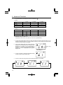
Filter factor number compensation (2) (608 CINE only)
1.
When using in cine industory, it is possible to set 7 different frequently used types of filters.
2.
Select setting number 1 and item number 2 in the custom setting mode.
3.
The symbol of the desired filter from among the 7 types can be selected by turning the Jog
wheel t while pressing ISO2 button y.
4.
After filter compensation, the filter symbol and cmpensated F value or EV value are displayed
while pressing ISO2 button.
Display in finder
Filters, LCD Display and Corrected Value
Filter Factor No.
85
NDO.3
85N3
85N6
85N9
LCD display
85-
n3-
NDO.6 NDO.9
n6-
n9-
A3-
A6-
A9-
Compensated value (EV)
-0.7
-1
-2
-3
-1.7
-2.7
-3.7
(Filter factor numbers are Kodak Wratten filter numbers.)
-31-
6. Advanced Functions
9.
Flash analyzing function
When measuring flash light, the shutter speed and F stop value (value combining ambient light and
flash light: total amount of light) are displayed in the liquid crystal display and the ambient light and
flash light are each displayed as separate values together with the total amount of light on the
analog scale. In addition, the ratio of flash light to the total amount of light is displayed at that time
as a value in 10% steps. It is possible to use this value for adjustments, for example, when
photographing with a flash in a room illuminated by tungsten light, to emphasize or weaken the
tungsten (ambient) light element (enhancing the flash light of the photograph) to match the
photographer's intentions.
< Example >
If, under certain conditions, the flash light component is
60% and the tungsten output component is 40%, the
display will be as indicated at the right. Flash reading on
the analog scale will blink.
1.
To emphasize the tungsten (ambient) light (to imbue
the atmosphere with orange-colored tones)
To increase the ratio of tungsten light, use the Jog
wheel t to change the shutter speed to a slower
setting.
It is apparent that the flash light component is now
20%. The analog scale also shows the tungsten
output component to be about 2.5 stop higher than
the flash light component.
As a result, images on the film are expressed with
orange tones that give life to the effect of the
tungsten light.
2.
To reduce the effect of tungsten light (to realize a
more natural atmosphere)
To decrease the ratio of tungsten light, use the Jog
wheel to change the shutter speed to a faster setting.
It is apparent that the flash light component is now
80%. The analog scale also shows the flash light
component to be about 1.5 stop higher than the
ambient light component.
As a result, the images on the film are expressed in
natural color tones.
Reference:
• Slower shutter speeds allow more available light to reach the film, and faster shutter
speeds allow less available light to reach the film.
• The settings above are made by adjusting the tungsten (ambient) light by the shutter speed. It
is also possible to modify the ratio by adjusting the flash light (when changing the distance
between the flash and the subject or when changing the amount of light of the flash). When
using this method, re-measure each time the flash light is adjusted.
-32-
6. Advanced Functions
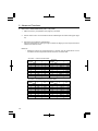
10. Custom setting function
It is possible to set the required functions in advance.
CUSTOM SETTING LIST
No.
Model
Lighting
Custom Setting name
1
608
Ambient &
Flash
ISO 2 setting
CINE
Item
0
1
Film
Sensitivity
1/3 step
Filter
compensation
(1)
0.1EV step
(±5EV)
2
3
—
—
Film
Sensitivity
1/3 step
Filter
Filter
compensation compensation
(1)
(2) 7 Filter
0.1EV step
factor
(±5EV)
numbers
—
2
608&CINE
Ambient &
Flash
Exposure Compensation
Display setting
Always
display
Not
display
—
—
3
*1
608&CINE
Ambient &
Flash
Increments of Shutter
Speed
full stop
1/3 stop
1/2 stop
—
4
*1
608&CINE
Ambient &
Flash
Increments of Aperture
full stop
1/3 stop
1/2 stop
—
5
608&CINE
Ambient
T priority mode
Available
Not
Available
—
—
6
608&CINE
Ambient
F priority mode
Available
Not
Available
—
—
7
608&CINE
Flash
Code-in mode
Available
Not
Available
—
—
8
608&CINE
Flash
Code-less mode
Available
Not
Available
—
—
9
608&CINE
Flash
Flash Analyzing function
Available
Not
Available
—
—
10
*2
608&CINE
Ambient
Illuminance or Luminance Compound + Compound
(CINE only) display
Individual
Individual
—
11
608&CINE
Ambient
Illuminance measurement Not Available
in Incident mode
LUX
FC
LUX, FC
12
CINE
Ambient
Luminance measurement Not Available
in Reflected mode
cd/m2
FL
cd/m2,
FL
-33-
6. Advanced Functions
*1 1/10 stop fractions are displayed in below combinations (
)
T priority
T 1 stop
T 1/3 stop
T 1/2 stop
F1/3 stop
–
–
–
F 1/2 stop
–
–
–
T 1 stop
F1 stop
F priority
T 1/3 stop
T 1/2 stop
F1 stop
–
–
F1/3 stop
–
–
F 1/2 stop
–
–
2
*2 Individual: LUX, FC, cd/m or FL
Compound: LUX+T+F, FC+T+F, cd/m2+T+F or FL+T+F (combination)
1.
To enter the custom setting mode, the meter must first be turned off. Set DIP switch 4 to on
position and turn the power on. It is not possible to enter the custom setting mode if DIP switch
4 is set to on after turning on the power.
2.
In the custom setting mode, 'CS' (custom setting) is
displayed in the ISO display area, a setting number
between 01-11 (608) or 01-12 (608 CINE) is
displayed in the shutter speed display area and item
number 0, 1, 2 or 3 is displayed in the aperture
display area.
Custom setting
item
Custom setting no.
-34-
3.
Turn the Jog wheel t and select the desired setting
number and the custom setting name.
4.
The item number will change each time the Mode set button !0 is pressed.
6. Advanced Functions
5.
Pressing the memory clear button @5 in the custom setting mode will reset all settings to default
(No.0).
6.
After completing the custom setting, terminate the custom setting mode by setting DIP switch 4
to off position. This operation will also automatically turn off the power.
Since the power cannot be turned off by pressing the power button while in the custom setting
mode, turn off the power by setting DIP switch 4 to off.
-35-
6. Advanced Functions
11. Wireless Flash radio triggering
With the radio transmitter module plugged into the meters radio socket and a receiver (RR-4 or RR32 sold separately, or PocketWizard® products) connected to one or more electronic flash units, the
meter provides a convenient system that enables one person working alone to measure flash output
without the need of a sync cord. Pressing the Measuring button simultaneously triggers the flash
and measures the light.
The L-608/608 CINE has 32 triggering channels when the radio triggering module (RT-32) is plugged
into the radio socket. Channels 1-16 provide single triggering, while channels 17-32 offer selective
quad-triggering capability. Selecting one of channels (17-32) provides control of up to four additional
sub-channels (A, B, C and D). Selecting or deselecting of zone lighting is possible with sub-channels.
In order to trigger flash units set for sub-channels, the electronic flash unit must be connected to the
RR-32 receiver or PlcketWizard MAX or MultiMax. With the RR-4 receiver or PocketWizard Plus
triggering channels 1-4 can be selected.
RT-32 radio transmitter
module
< Example with optional 32 channels receiver >
1.
Open battery compartment cover !6 , remove
connector cover and set the RT-32 radio transmitter
module (optional) by aligning the connector with the
pins.
CAUTION
• To prevent damage due to static electricity, release static electricity stored in your body
by touching a metal object nearby (door knob, aluminum window frame, etc.) before
touching the radio transmitter module.
2.
Switch to the Wireless flash radio triggering setting
mode by using Jog wheel t while pressing mode
.
set button !0
MODE
-36-
6. Advanced Functions
3.
The set channel number will blink on and off at this time.
Turn the Jog wheel to set the channel setting.
4.
In the Setting mode, "ch" appears on the ISO display area. At the same time, channel numbers
(1 to 16 and 17 to 32) appear on the F display area. When the channel number is 17 to 32, subchannel (A, b, c and d) settings are displayed on the T indicator. In the absence of settings, "" appears in the figures.
5.
In sub-channel settings, after the channel is set to 17 to 32, the mode button is pressed. Following
this, the 4th figure on the T display area blinks to indicate that settings may be made. Every
time the mode button is pressed, the blinking settings shifts from sub-channel No. : 4th figure →
3rd figure → 2nd figure → 1st figure → channel No., while permitting settings for each subchannel. As the Jog wheel is rotated in this state, setting ("A, b, c and d" displayed) and
resetting ("-" displayed) alternate. During this process, the indicator continues to blink to indicate
the channel being set.
→ Set by manipulating the mode set button.
↔ Set by manipulating the Jog wheel.
CAUTION
• When using quad channels 17-32, it is not possible to terminate this mode unless a subchannel has been set (a, b, c or d is displayed).
-37-
6. Advanced Functions
6.
Upon setting completion, the Wireless flash radio triggering mode or Wireless multiple flash
radio triggering mode is selected using the Jog wheel while the Mode set button is pressed. For
other settings of the measurement, see page 16.
7.
Confirm that the meter and the radio receiver are set to the same channel number. The flash
unit will fire when the measurement button of the meter is pressed and measurements can be
made at the same time.
Reference:
• Refer to the receiver instruction manual for the receiver operating method.
• Maximum controllable distance of the radio flash trigger system differs depending on the
placement of the device, direction and other factors.
1. Confirm the direct visible range between the transmitter and receiver.
2. Place the meter and receiver away from large metal objects, concrete, objects with
large moisture content (both people and trees fall into the category) and so forth.
3. Secure the radio receiver in place by using Velcro tape or mounting 1/4-20 thread.
Be sure that the entire length of the receiver antenna is higher than the flash pack at
this time. Avoid contact between the receiver antenna and metal objects at all times.
4. Depending on the location, there may be cases when the receiver is incapable of
receiving any radio signals whatsoever.
There are various possible reasons for this such as radio signals reflected from nearby
objects. This can generally be resolved by shifting the device slightly in one direction
or another.
In addition, confirm that the device is not placed behind objects that readily absorb or
deflect radio signals such concrete, metal, low hills, etc.
NOTE:
• The radio flash system may be used only in countries where a permit for the control
frequency has been issued by the government office in charge.
-38-
7. Accessories
Mini Light Receptor (Sold separately)
•
•
Incident light receiving unit with a compact 12mm diameter
light receiving surface.
For measuring narrow areas used for photographing small
subjects or copy work.
Synchro cord (Sold separately)
•
This is a five-meter long cord with three plugs. An exposure
meter, a camera, and a flash can all be connected at the
same time. This is convenient when measurements are
made, because it is not necessary to plug and unplug the
synchro cord.
18% Gray Card (Sold separately)
•
18% gray card with cover (110mm x 102mm, 4 1/4" x 3 1/
2"), folds to 2 3/4" x 4 3/4", and fits in a shirt pocket.
•
It provides accurate exposures regardless of reflected ratio of the subject and surroundings.
-39-
7. Accessories
Wireless flash radio triggering system (Sold separately)
•
Combining radio transmitter module (RT-32) with radio receiver (RR-32 or RR-4) enables
measurements by triggering the flash from the exposure meter.
Radio transmitter module
(RT-32, 32 channels)
Radio wave receiver
(RR-32, 32 channels)
Radio wave receiver
(RR-4, 4 channels)
Reference:
• RT-32 transmitter module, RR-4 and RR-32 receivers are compatible with Pocket
Wizard® products from LPA Design.
• Light receiving angle 54° (Lumigrid) (Sold separately)
This method measures the brightness (luminance) of the light
reflected from the subject. It is useful for distant objects such
as landscapes, when you cannot go to the position of the
subject, or for metering subjects that generate light (neon
signs, etc.), highly reflective surfaces or translucent subjects
(stained glass, etc.).
• Step-Up Ring (30.5mm → 40.5mm) (Sold separately)
The step-up ring, available as an optional accessory, makes
it possible to mount step rings and filters of other
manufacturers. This simplifies the setting of exposure without
the troublesome correction calculation of PL filters, etc.
The step-up ring can also be used as a hood to protect lenses
from scratching, soiling, etc.
• 2x Angle Converter (optional) (Sold separately)
Mounting the 2x angle converter to the objective lens unit
enables zoom measurements at a light receiving angle of 2°8°.
-40-
8. Technical Data
· Type
: Digital exposure meter for ambient and flash light
· Light receiving method
: Incident light and reflected light
· Light Receptors
Incident light
Reflected light
· Light receptor element
· Metering modes
Ambient light
Flash
: Convertible to flat diffuser (Lumisphere in down position)
: 1° to 4° element Zoom (display in finder)
Metering distance 1m ~ ∞
: 2-Silicon photo diodes (incident and reflected)
: Aperture priority metering
Shutter priority metering
EV metering
Simple illumination measurement (lux, foot-candle)
Simple brightness measurement (608 Cine only)
(foot-lambert, cd/m2)
: With synchro cord (cumulative, non-cumulative)
Without synchro cord (cumulative, non-cumulative)
Measurement using the optional wireless flash radio triggering sysytem
(cumulative, non-cumulative)
· Measuring Range (ISO 100) :
Ambient light
Incident light
: EV-2 to EV 22.9
Reflected light
: EV 3 to EV 24.4 (with 1° ~ 4° zoom spot viewfinder)
EV-2 to EV 22.9 (with optional 54° Lumigrid)
Flash
Incident light
: f0.5 to f128.9 (approx. f175)
Reflected light
: f5.6 to f128.9 (approx. f175) (with 1° ~ 4° zoom spot viewfinder)
f0.5 to f128.9 (approx.f175) (with optional 54° Lumigrid)
Illumination
: 0.63 - 190,000 lux (2 significant digits)
0.12 - 180,000 foot-candle (2 significant digits)
Brightness (608 Cine only) : 1 - 190,000 cd/m2 (2 significant digits)
0.3 - 190,000 foot-lambert (2 significant digits)
· Repeat Accuracy
: +/- 0.1 EV or less
· Calibration Constant
Incident light metering
Reflected light metering
: Lumisphere C = 340 Flat diffuser C = 250
: K = 12.5
· Display Range
Film speed
Shutter Speeds
Ambient light
Flash
: ISO 3 to 8000 (in 1/3 steps)
: 30 minutes to 1/8000 seconds(in 1, 1/2 or 1/3 stop)also 1/200, 1/400
Cine speeds- 2, 3, 4, 6, 8, 12, 16, 18, 24, 25, 30, 32, 36, 40, 48, 50,
60, 64, 72, 96, 120, 128, 150, 200, 240, 256, 300, 360 frames per
second (at a 180 degree shutter angle)
(608 Cine addition)
1, 75, 90, 100, 125, 250, 375, 500, 625, 750, 1000
: 30 minutes to 1/1000 second (in 1, 1/2 or 1/3 stop),also 1/75, 1/80, 1/
90, 1/100, 1/200, 1/400
-41-
8. Technical Data
Aperture
: f/0.5 to f/161 (in 1, 1/2 or 1/3 stop)
f/0.5 to f/161 (in 1, 1/2 or 1/3 stop) (608 CINE)
EV
: EV -9.9 to EV 41.6 (in 1/10 stop)
Analog scale
: F1.0 - F128 (in 1/2 stop),T4.0 seconds -1/4000 seconds (in 1/2
stop)(608)
F0.5 - F45 (in 1/3 stop) (608 CINE)
Shutter angle (608 Cine only)
: 5° ~ 270° (in 5°stop), others: 144°, 172°
Filter compensation
: +/- 5.0 EV (in 1/10 stop)
Filter factor numbers (608 Cine only)
: 85-, n3-, n6-, n9-, A3-, A6-, A9· Other features
:
All-weather feature
: JIS standard water resistance class 4, splash-proof type
Memory function
: 9 readings
Memory clear recall function
Multiple Flash function
: Up to ∞ flash readings (only one digit is displyed when the cumulated
number is ten or more.)
Average function
: up to 9 readings can be averaged.
Brightness Difference function : +/- 9.9 EV (in 1/10 stop)
Flash analyzing function : 0 to 100% in 10% increments
Exposure Out of Range
: Eu (underexposure) or Eo (overexposure) indication
Exposure compensation : +/- 9.9 EV (in 1/10 stop)
Calibration compensation : +/- 1.0 EV (in 1/10 stop)
Battery Power Indicator display: with 3 level status icon
Auto Power Off
: approx. 20 minutes after last use
Auto illumination
: EV 6 and under
DIP switch mode selection
1/4” Tripod socket
: For placing meter in subject area for cordless flash measuring.
Second ISO film speed setting: ISO 3 to 8000 (in 1/3 stop)
Diopter adjustment
: -2.5 to 1.0d
· Battery used
: one of CR123A battery (lithium dry cell)
· Operating temperature range : -10 ~ 50°C
· Storage temperature range
: -20 ~ 60°C
· Dimensions
:
90 w × 170 h × 48 d mm
· Weight
:
268 g (with battery)
· Standard accessories supplied : Soft case, strap, lens cap, synchro terminal cap, CR123A lithium
battery × 1
· Radio triggering range
: approx. 30 meters (approx. 100 feet)
· Radio wave frequency
FCC & IC
: CH1 ~ 16
344.0MHz
CH17 ~ 32
346.5 ~ 354.0MHz
CE
: CH1 ~ 16
433.62MHz
CH17 ~ 32
434.22MHz
Features and specifications are subject to change without notice.
-42-
9. Safety Guide
WARNING:
• Please keep in a location where an infant cannot reach and accidentally
get the strap wrapped around his neck. There is danger of strangulation.
• Never place batteries in fire, short, disassemble, or heat them. The batteries
might break down, and cause injury or pollute the environment.
CAUTION:
• Do not look directly at the sun through the viewfinder, because of potential
eye injury.
• If you are operating the exposure meter in areas under wet conditions or
high humidity, keep the sync post covered. If you are using flash in these
conditions, Cordless Flash mode is recommended.
-43-
10. Care and Maintainance
NOTE:
• Although this meter has an All-weather design for everyday use (JIS standard water
resistance class 4), do not place it in water or use it underwater. This will cause it to
malfunction.
Splashed
Rain
Do not wash with water
Do not submerge or use under water
• To avoid damaging this meter, never drop it or subject it to shock.
• Avoid storing it in places with high temperatures or humidity.
• Avoid excessive temperature changes which could cause internal condensation,
resulting in malfunction.
Maintenance Notes
• If your meter is splashed with water, wipe immediately with a soft dry cloth.
• Avoid applying excessive force on the rubber seal of the battery compartment cover.
Do not attempt to remove the rubber seal of the battery compartment cover.
• If the rubber seal’s surface is damaged,water or moisture may enter and damage the
meter. If this has happened, you must send your meter to the Sekonic Sevice Center in
your country.
• Keep the surface of the Lumisphere and the front and rear surface of the Zoom lens
free from dust, dirt, and scratches, which could affect accuracy.
• Never use organic cleaners (like thinner or benzene). Clean with soft dry cloth.
-44-
FCC & IC compliance information:
Warning: Changes or modifications to this unit not expressly approved by the party responsible for
compliance could void the user's authority to operate the equipment.
Note: This equipment has been tested and found to comply with the limits for a Class B digital device,
pursuant
To Part 15 of the FCC Rules. These limits are designed to provide reasonable protection against harmful
interference in a residential installation. This equipment generates, uses, and can radiate radio frequency
energy and, if not installed and used in accordance with the instruction, may cause harmful interference
to radio communication.
However, there is no guarantee that interference will not occur in a particular installation. If this equipment
does cause harmful interference to radio or television reception, which can be determine by turning the
equipment off and on, the user is encouraged to try to correct the interference by one or more of the
following measures:
* Reorient or relocate the receiving antenna.
* Increase the separation between the equipment and receiver.
* Consult the dealer or an experienced radio/TV technician for help.
This device complies with Part 15 of the FCC rules and also with RSS-210 of Industry & Science Canada.
Operation is subject to the following two condition: (1) This device may not cause harmful interference,
and (2) this device must accept any interference received, including interference that may cause undesired
operation.
FCC ID Number: PFK-608-01
Canada: 3916104181
-45-
Memo
-46-
7-24-14. Oizumi-Gakuen-cho, Nerima-ku, Tokyo 178-8686, Japan
Phone:++81-3-3978-2335 Facsimile:++81-3-3978-5229
EU DECLARATION OF CONFORMITY
THE EU DIRECTIVE COVERED BY THIS DECLARATION:
Radio & Telecommunications Terminal Equipment Directive 1999/5/EC
PRODUCT COVERED BY THIS DECLARATION:
Name: Super Zoom Master
Model: L-608/L-608CINE
THE BASIS ON WHICH CONFORMITY IS BEING DECLARED:
The Super Zoom Master L608/L-608CINE complies with the essential requirements of the Radio &
Telecommunications Terminal Equipment Directive 1999/5/EC on the basis of Technical
Construction File Number: R-3720N assessed by the Notified Body:
SGS EMC Services
South Industrial Estate
Bowburn
Co. Durham DH6 5AD
United Kingdom
Printed Name: Makoto Tomono
Signed: ___________________________
Title: President
Date: April 20, 2001
Note: The device makes use of a radio frequency and which is not harmonized throughout the EU.
7-24-14, OIZUMI-GAKUEN-CHO, NERIMA-KU, TOKYO 178-8686 JAPAN
TEL:+81(0) 3-3978-2335
FAX:+81(0)3-3978-5229
JB???????-00
02.7.5000.PF