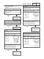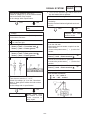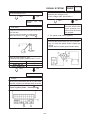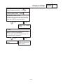
1
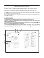
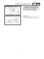
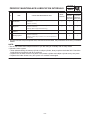
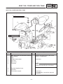
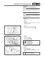
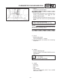
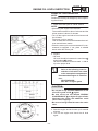
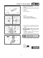
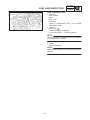
FOREWORD This Supplementary Service Manual has been prepared to introduce new service and data for the TDM850 ’99. For complete service information procedures it is necessary to use this Supplementary Service Manual together with the following manual. TDM850 ’96 SERVICE MANUAL: 4TX-AE1 TDM850 ’97 SUPPLEMENTARY SERVICE MANUAL: 4TX-AE2 TDM850 ’99 SUPPLEMENTARY SERVICE MANUAL 1998 by Yamaha Motor Co., Ltd. First Edition, November 1998 All rights reserved. Any reproduction or unauthorized use without the written permission of Yamaha Motor Co., Ltd. is expressly prohibited. EB001000 NOTICE This manual was produced by the Yamaha Motor Company primarily for use by Yamaha dealers and their qualified mechanics. It is not possible to include all the knowledge of a mechanic in one manual, so it is assumed that anyone who uses this book to perform maintenance and repairs on Yamaha motorcycles has a basic understanding of the mechanical ideas and the procedures of motorcycles repair. Repairs attempted by anyone without this knowledge are likely to render the motorcycles unsafe and unfit for use. Yamaha Motor Company, Ltd. is continually striving to improve all its models. Modifications and significant changes in specifications or procedures will be forwarded to all authorized Yamaha dealers and will appear in future editions of this manual where applicable. NOTE: Designs and specifications are subject to change without notice. IMPORTANT INFORMATION Particularly important information is distinguished in this manual by the following notations. The Safety Alert Symbol means ATTENTION! BECOME ALERT! YOUR SAFETY IS INVOLVED! Failure to follow WARNING instructions could result in severe injury or death to the motorcycle operator, a bystander or a person inspecting or repairing the motorcycle. CAUTION: NOTE: A CAUTION indicates special precautions that must be taken to avoid damage to the motorcycle. A NOTE provides key information to make procedures easier or clearer. EB002000 HOW TO USE THIS MANUAL MANUAL ORGANIZATION This manual consists of chapters for the main categories of subjects. (See “Illustrated symbols”) 1st title 1 : This is the title of the chapter with its symbol in the upper right corner of each page. 2nd title 2 : This title indicates the section of the chapter and only appears on the first page of each section. It is located in the upper left corner of the page. 3rd title 3 : This title indicates a sub-section that is followed by step-by-step procedures accompanied by corresponding illustrations. EXPLODED DIAGRAMS To help identify parts and clarify procedure steps, there are exploded diagrams at the start of each removal and disassembly section. 1. An easy-to-see exploded diagram 4 is provided for removal and disassembly jobs. 2. Numbers 5 are given in the order of the jobs in the exploded diagram. A number that is enclosed by a circle indicates a disassembly step. 3. An explanation of jobs and notes is presented in an easy-to-read way by the use of symbol marks 6 . The meanings of the symbol marks are given on the next page. 4. A job instruction chart 7 accompanies the exploded diagram, providing the order of jobs, names of parts, notes in jobs, etc. 5. For jobs requiring more information, the step-by-step format supplements 8 are given in addition to the exploded diagram and the job instruction chart. 2 1 4 3 6 8 5 7 EB003000 1 GEN INFO 3 2 ILLUSTRATED SYMBOLS SPEC Illustrated symbols 1 to 9 are printed on top right of each page and indicate the subject of each chapter. 4 1 General information 2 Specifications INSP ADJ ENG 3 Periodic inspection and adjustment 4 Engine 5 5 Cooling system 6 6 Carburetion COOL CARB 7 Chassis 8 Electrical 7 9 Troubleshooting 8 CHAS ELEC Illustrated symbols 10 to 17 are used to identify the specifications appearing in the text. 10 9 TRBL SHTG 10 Can be serviced with engine mounted 11 Filling fluid 12 Lubricant 11 12 13 Special tool 14 Torque 15 Wear limit, clearance 13 15 16 Engine speed 14 16 17 Ω, V, A 17 Illustrated symbols 18 to 23 in the exploded diagrams indicate the types of lubricants and lubrication points. 18 Apply engine oil 19 Apply gear oil 18 19 20 20 Apply molybdenum disulfide oil 21 Apply wheel bearing grease 22 Apply lightweight lithium-soap base grease 23 Apply molybdenum disulfide grease 21 22 23 Illustrated symbols 24 to 25 in the exploded diagrams indicate where to apply a locking agent 24 and when to install new parts 25 . 24 25 24 Apply locking agent (LOCTITE) 25 replace CONTENTS GENERAL INFORMATION . . . . . . . . . . . . . . . . . . . . . . . . . . . . . . . . . . . . . . . . MOTORCYCLE IDENTIFICATION . . . . . . . . . . . . . . . . . . . . . . . . . . . . . . . VEHICLE IDENTIFICATION NUMBER . . . . . . . . . . . . . . . . . . . . . . . . MODEL LABEL . . . . . . . . . . . . . . . . . . . . . . . . . . . . . . . . . . . . . . . . . . . . 1 1 1 1 SPECIFICATIONS . . . . . . . . . . . . . . . . . . . . . . . . . . . . . . . . . . . . . . . . . . . . . . . . GENERAL SPECIFICATIONS . . . . . . . . . . . . . . . . . . . . . . . . . . . . . . . . . . . MAINTENANCE SPECIFICATIONS . . . . . . . . . . . . . . . . . . . . . . . . . . . . . . ENGINE . . . . . . . . . . . . . . . . . . . . . . . . . . . . . . . . . . . . . . . . . . . . . . . . . . CHASSIS . . . . . . . . . . . . . . . . . . . . . . . . . . . . . . . . . . . . . . . . . . . . . . . . . ELECTRICAL . . . . . . . . . . . . . . . . . . . . . . . . . . . . . . . . . . . . . . . . . . . . . CABLE ROUTING . . . . . . . . . . . . . . . . . . . . . . . . . . . . . . . . . . . . . . . . . . . . . 2 2 3 3 3 4 5 PERIODIC INSPECTION AND ADJUSTMENT . . . . . . . . . . . . . . . . . . . . . . . INTRODUCTION . . . . . . . . . . . . . . . . . . . . . . . . . . . . . . . . . . . . . . . . . . . . . . PERIODIC MAINTENANCE/LUBRICATION INTERVALS . . . . . . . . . . . SEAT, TAIL COVER AND FUEL TANK . . . . . . . . . . . . . . . . . . . . . . . . . . . SEAT, TAIL COVER AND FUEL TANK . . . . . . . . . . . . . . . . . . . . . . . . ENGINE . . . . . . . . . . . . . . . . . . . . . . . . . . . . . . . . . . . . . . . . . . . . . . . . . . . . . . CARBURETOR SYNCHRONIZATION . . . . . . . . . . . . . . . . . . . . . . . . ENGINE OIL LEVEL INSPECTION . . . . . . . . . . . . . . . . . . . . . . . . . . . ENGINE OIL REPLACEMENT . . . . . . . . . . . . . . . . . . . . . . . . . . . . . . . FUEL LINE INSPECTION . . . . . . . . . . . . . . . . . . . . . . . . . . . . . . . . . . . CLUTCH . . . . . . . . . . . . . . . . . . . . . . . . . . . . . . . . . . . . . . . . . . . . . . . . . . . . . CLUTCH . . . . . . . . . . . . . . . . . . . . . . . . . . . . . . . . . . . . . . . . . . . . . . . . . . INSTALLATION . . . . . . . . . . . . . . . . . . . . . . . . . . . . . . . . . . . . . . . . . . . . 13 13 13 15 15 16 16 18 19 21 22 22 23 INSTRUMENT FUNCTIONS . . . . . . . . . . . . . . . . . . . . . . . . . . . . . . . . . . . . 24 COMBINATION METER . . . . . . . . . . . . . . . . . . . . . . . . . . . . . . . . . . . . 24 SIGNAL SYSTEM . . . . . . . . . . . . . . . . . . . . . . . . . . . . . . . . . . . . . . . . . . . . . CIRCUIT DIAGRAM . . . . . . . . . . . . . . . . . . . . . . . . . . . . . . . . . . . . . . . . TROUBLESHOOTING . . . . . . . . . . . . . . . . . . . . . . . . . . . . . . . . . . . . . . SIGNAL SYSTEM CHECK . . . . . . . . . . . . . . . . . . . . . . . . . . . . . . . . . . 25 25 27 28 FUEL PUMP SYSTEM . . . . . . . . . . . . . . . . . . . . . . . . . . . . . . . . . . . . . . . . . CIRCUIT DIAGRAM . . . . . . . . . . . . . . . . . . . . . . . . . . . . . . . . . . . . . . . . FUEL PUMP CIRCUIT OPERATION . . . . . . . . . . . . . . . . . . . . . . . . . . TROUBLESHOOTING . . . . . . . . . . . . . . . . . . . . . . . . . . . . . . . . . . . . . . CHECKING THE FUEL PUMP . . . . . . . . . . . . . . . . . . . . . . . . . . . . . . . 32 32 33 34 36 TDM850 ’99WIRING DIAGRAM MOTORCYCLE IDENTIFICATION GEN INFO EB100000 GENERAL INFORMATION MOTORCYCLE IDENTIFICATION VEHICLE IDENTIFICATION NUMBER The vehicle identification number 1 is stamped into the right side of the steering head. MODEL LABEL The model label 1 is affixed to the frame. This information will be needed to order spare parts. –1– GENERAL SPECIFICATIONS SPECIFICATIONS GENERAL SPECIFICATIONS Item Standard Model: TDM850 Model code: 4TX4 Basic weight (With oil and full fuel tank): 232 kg Carburetor: Type/quantity Manufacturer BDSR38/2 MIKUNI Transmission Primary reduction system Primary reduction ratio Secondary reduction system Secondary reduction ratio Transmission type Operation Gear ratio Bulb wattage quantity Meter light Indicator lights Neutral Turn High beam Fuel Water tempere 1st 2nd 3rd 4th 5th Spur gear 67/39 (1.718) Chain drive 43/16 (2.688) Constant mesh 5-speed Left foot operation 37/14 (2.643) 37/19 (1.947) 30/20 (1.500) 27/23 (1.174) 27/28 (0.964) 12V 2 W 3 14 V 1.4 W 1 14 V 1.4 W 2 14 V 1.4 W 1 12 V 2 W 1 14 V 1.4 W 1 –2– SPEC MAINTENANCE SPECIFICATIONS SPEC MAINTENANCE SPECIFICATIONS ENGINE Item Standard Limit Clutch: Clutch spring free length Quantity 50 mm 6 48 mm Carburetor: I.D. mark Main jet Main air jet Jet needle Needle jet Pilot air jet 1 Pilot air jet 2 Pilot outlet Pilot jet Bypass 1 Bypass 2 Bypass 3 Pilot screw Valve seat size Starter jet 1 Starter jet 2 Throttle valve size Fuel level Engine idle speed Intake vacuum 4TX4 40 #147.5 #65 #1: 6DJP17 #2: 6CL1 P-O #87.5 #120 1.0 #17.5 0.8 0.9 0.8 2.0 1.5 #32.5 0.9 #95 4.4 X 5.4 mm 1050 X 1250 r/min 36.0 X 38.7 kPa (270 X 290 mmHg) Fuel pump: Type Model/manufacturer Output pressure Electrical type 4TX/MITSUBISHI 7 kPa (0.07 kgf/cm2, 0.07 bar) CHASSIS Item Fuel sender and fuel tank Fuel pump and bracket Bracket and frame Thread size M5 M6 M6 –3– Tightening torque Nm mkgf 3.8 6.5 6.5 0.38 0.65 0.65 Remarks MAINTENANCE SPECIFICATIONS SPEC ELECTRICAL Item Standard Limit Charging system: Type Model/manufacturer Nominal output Stator coil resistance A.C. magneto TLN252/DENSO 14 V 25 A at 5,000 r/min 0.23 X 0.35 Ω at 20_C/W-W SSS SSS SSS SSS Starter relay: Model/manufacturer Amperage rating Coil winding resistance MS5F-421 /JIDECO 180 A 4.2 X 4.6 Ω at 20_C SSS SSS SSS 4TX/NIPPON/SEIKI 4 X 10Ω 90 X 100Ω SSS SSS SSS Fuel pump relay: Model/manufacturer Coil winding resistance G8R-30Y-B/OMRON 225 Ω ± 10% SSS SSS Hazard relay: Model/manufacturer Coil winding resistance 4KM-00/MATSUSHITA 72 X 88 Ω at 20_C SSS SSS Fuse SSS 30 A 1 15 A 1 15 A 1 10 A 1 10 A 1 7.5 A 1 5A 1 15 A 1 10 A 1 5A 1 SSS SSS SSS SSS SSS SSS SSS SSS SSS SSS Fuel sender: Model/manufacturer resistance full empty Circuit breakers: Type Amperage for individual circuits Main fuse Headlight fuse Signal system fuse Ignition fuse Fuse (position light and hazard) Radiator fan fuse Back up Reserve fuse Reserve fuse Reserve fuse –4– CABLE ROUTING SPEC CABLE ROUTING 1 2 3 4 5 6 7 8 9 10 11 12 13 14 15 Throttle cable 1 Right handlebar switch lead Brake hose Clutch cable Main switch lead Left handlebar switch lead Horn lead Starter cable Speed sensor lead Coolant reservoir hose Headlight lead Meter light lead Thermo unit lead Thermo switch lead Fan motor lead 16 Ignition coil (left) lead 17 Ignition coil (right) lead 18 Negative lead A Fasten the right handlebar switch lead with a plastic band. B Fasten the handlebar switch lead with a plastic band. C 50 mm D Fasten the horn lead with a plastic band. E 60 mm F Set the clamp within 10 mm from the upper end of protector. –5– G Align the brake hose white mark to the mark of bracket. H Fasten the brake hose with a plastic band and cut the end of band. I Pass the speed sensor lead between throttle cable and clutch cable and fasten to the frame head pipe. J Pass the wireharness and hoses under the frame. K Fasten the coolant reservoir hose with a plastic band. CABLE ROUTING L Fasten the meter lead and headlight lead with a plastic band. M Fasten the wireharness with a plastic band. N Fasten the wireharness, right handlebar switch lead meter lead and headlight lead with a plastic band. O Connect the coupler and insert to the protector. SPEC P Fasten the wireharness with a plastic band. Q Fasten the wireharness and ignition coil (left) lead with a plastic band. R Fasten the wireharness right handlebar switch lead, main switch lead fan motor lead with a plastic band. S Set the ignition coil at the mark upward. T Protector is under the coupler. –6– CABLE ROUTING 1 2 3 4 5 6 7 8 9 10 Front flasher light (left) lead Main switch lead Starter cable 1 Left handlebar switch lead Spark plug lead Carburetor breather hose Fuel hose Coolant reservoir hose Sidestand switch lead Neutral switch lead 11 12 13 14 15 16 17 18 19 20 A.C. magneto lead Air filter case breather hose Carburetor heater hose Starter cable 2 Thermo switch lead Brake hose Speed sensor lead Wire harness Flasher relay lead Fuel pump lead –7– SPEC A Fasten the left handlebar switch lead and main switch lead with a plastic band. B Route the wireharness to the rearside of the frame pipe. C Route the starter cable through radiator hose upward and spark plug lead rear side and in front of air filter case breather hose. Route the spark plug lead to the outside of the carburetor starter bracket and carburetor heater hose. CABLE ROUTING D Fasten the rear flasher light (left) lead. E Fasten the sidestand switch lead neutral switch lead and A.C. magneto lead. F Route the sidestand switch lead and air filter case breather hose to the inside of the engine cover. G Fasten the sidestand switch lead to the air filter case breather hose. H Route the air filter case breather hose over the idle adjust bracket. I Route the air filter case breather hose to the outside of the carburetor heater hose and route the carburetor heater hose to the inside of the air filter case breather hose. SPEC J Clamp the speed sensor lead to the outer tube with a holder. K Clamp the speed sensor lead along the brake hose (three position). L Connect the coupler and insert the protector. Set the protector between crosstube and fuel pump. M Fasten the coolant reservoir hose, A.C. magneto lead, neutral switch lead and sidestand switch lead. –8– CABLE ROUTING 1 2 3 4 5 6 7 8 9 10 11 12 13 14 15 16 Battery negative lead Battery positive lead Starter motor lead Fuel sender lead Fuel tank drain hose Fuel tank breather hose (for DEU) Water hose Spark plug lead Clutch cable Brake hose Throttle cable Right handlebar switch lead Headlight lead Meter light lead Speed sensor lead Carburetor heater hose 17 18 19 20 21 22 Vacuum hose (#1) Vacuum hose (#2) Coolant reservoir breather hose Carburetor breather hose Rear brake switch lead CYCLELOCK lead A Route the battery positive lead and battery negative lead through the clamp. B Fasten the wireharness Coolant breather hose and flasher relay lead. C Route the carburetor breather hoses through the engine clamp. –9– SPEC D Fasten the carburetor air vent hose. E Route the carburetor breather hoses, vacuum hose (#1) down ward and vacuum hose (#2) upward through the guide. F Route the vacuum hose (#1) inside, vacuum hose (#2) outside through the guide. G Fasten the coolant reservoir hose. H Fasten the wireharness right handlebar switch lead meter lead and headlight lead with a clamp. I Route the relay lead through the outside of wireharness. CABLE ROUTING J Fasten the right handlebar switch lead and speed sensor lead with a clamp. K Fasten the throttle cable and speed sensor lead with a clamp. L Route the coolant reservoir hose through the outside of clutch cable. M Fasten the wireharness, right handlebar switch lead, meter lead and headlight lead with a clamp. N Route the clutch cable through the guide of stay. O Route the coolant reservoir breather hose, fuel tank drain hose, carburetor breather hose through the guide. P Route the carburetor breather hoses through the clamp. Q Route the fuel tank drain hose, fuel tank breather hose through the hole of the frame bracket. R Route the coolant reservoir breather hose, fuel tank breather hoseand fuel tank drain hose through the guide. S T U V W –10– SPEC Route the brake switch lead through the guide. Fasten the wireharness, rear flasher lead with a clamp. Fasten the wireharness with a clamp. Fasten the coolant reservoir breather hose with a clamp. To the engine. CABLE ROUTING 1 2 3 4 5 6 7 8 9 10 11 Head light lead Wireharness Meter light lead Throttle cable Throttle stop screw cable Vacuum hose (#2) Vacuum hose (#1) Fuel tank breather hose Fuel hose Carburetor air vent hose Carburetor breather hose 12 13 14 15 16 17 18 19 20 21 22 23 Fuel tank drain hose Fuel hose Fuel sender lead Starter motor lead Battery positive lead Battery negative lead Coolant reservoir breather hose Coolant reservoir hose Fuel hose Carburetor breather hose Cylinder head breather hose Air filter case breather hose –11– SPEC A Fasten the meter lead, headlight lead wireharness with a clamp. B Fasten the wireharness, coolant reservoir hose with a clamp. C Fasten the fuel hose with a clamp. D Route the starter relay lead and fuel sender lead through the guide of bracket. E Connect the coupler and insert the protector. F Fasten the taillight lead to the taillight bracket above left taillight with a clamp and end of clamp is downward. G 50 mm CABLE ROUTING H Fasten the carburetor breather hose and see the hose mark. I In order to carburetor breather hose, idle adjust cable coolant breather hose from downward. J Route the air filter drain hose to outside of throttle position sensor lead. K Fasten the wireharness with a clamp. L To left flasher. M Fasten the headlight lead with a clamp. N O P Q R SPEC To head light. To auxiliary light. To meter. Fasten the meter lead, headlight lead with a clamp. Fasten the meter lead, headlight lead and right flasher lead connecter with a clamp. S To right flasher. T Fasten the meter lead, headlight lead, relay assembly lead and right flasher lead with a clamp. –12– INTRODUCTION/ PERIODIC MAINTENANCE/LUBRICATION INTERVALS INSP ADJ PERIODIC INSPECTION AND ADJUSTMENT INTRODUCTION This chapter includes all information necessary to perform recommended inspection and adjustments. These preventive maintenance procedures, if followed, will ensure more reliable vehicle operation and a longer service life. The need for costly overhaul work will be greatly reduced. This information applies to vehicles already in service as well as new vehicles that are being prepared for sale. All service technicians should be familiar with this entire chapter. PERIODIC MAINTENANCE/LUBRICATION INTERVALS EVERY NO. ITEM CHECKS AND MAINTENANCE JOBS 1 * Fuel line Check fuel hoses for cracks or damage. Replace if necessary. 2 * Fuel filter Check condition. Replace if necessary. Spark plugs Check condition. Clean, regap or replace if necessary. Valves Check valve clearance. Adjust if necessary. 5 Air filter Clean or replace if necessary. 6 Clutch Check operation. Adjust or replace cable. 3 4 * INITIAL (1,000 km) 6,000 km or 6 months (whichever comes first) 12,000 km or 12 months (whichever comes first) √ √ √ √ √ √ Every 42,000 km or 42 months (whichever comes first) √ √ √ √ √ 7 * Front brake Check operation, fluid level and vehicle for fluid leakage. Correct accordingly. Replace brake pads if necessary. √ √ √ 8 * Rear brake Check operation, fluid level and vehicle for fluid leakage. Correct accordingly. Replace brake pads if necessary. √ √ √ 9 * Wheels Check balance, runout and for damage. Rebalance or replace if necessary. √ √ 10 * Tires Check tread depth and for damage. Replace if necessary. Check air pressure. Correct if necessary. √ √ 11 * Wheel bearings Check bearing for looseness or damage. Replace if necessary. √ √ 12 * Swingarm Check swingram pivoting point for play. Correct if necessary. Lubricate with molybdenum disulfide grease every 24,000 km or 24 months (whichever comes first). √ √ 13 Drive chain Check chain slack. Adjust if necessary. Make sure that the rear wheel is properly aligned. Clean and lubricate. Every 500 km and after washing the motorcycle or riding in the rain 14 * Steering bearings Check bearing play and steering for roughness. Correct accordingly. Lubricate with lithium soap base grease every 24,000 km or 24 months (whichever comes first). √ √ 15 * Chassis fasteners Make sure that all nuts, bolts and screws are properly tight ened. Tighten if necessary. √ √ 16 Sidestand Check operation. Lubricate and repair if necessary. √ √ 17 * Sidestand switch Check operation. Replace if necessary. √ √ 18 * Front fork Check operation and for oil leakage. Correct accordingly. √ √ 19 * Rear shock absorber assembly Check operation and shock absorber for oil leakage. Replace shock absorber assembly if necessary. √ √ 20 * Rear shock absorber assembly pivoting points √ √ √ Check operation. Lubricate with molybdenum disulfide grease every 24,000 km or 24 months (whichever comes first). –13– PERIODIC MAINTENANCE/LUBRICATION INTERVALS INSP ADJ EVERY NO. ITEM CHECKS AND MAINTENANCE JOBS INITIAL (1,000 km) 6,000 km 6 months (whichever comes first) 12,000 km 12 months (whichever comes first) 21 * Carburetors Check engine idling speed, synchronization and starter oper ation. Adjust if necessary. √ √ √ 22 Engine oil Check oil level and vehicle for oil leakage. Correct if necessary. Change. (Warm engine before draining.) √ √ √ 23 Engine oil filter element Replace. √ 24 * Cooling system Check coolant level and vehicle for coolant leakage. Correct if necessary. Change coolant every 24,000 km or 24 months (whichever comes first). √ √ √ * Since these items require special tools, data and technical skills, they should be serviced by a Yamaha dealer. NOTE: The air filter needs more frequent service if you are riding in unusually wet or dusty areas. Hydraulic brake system When disassembling the master cylinder or caliper cylinder, always replace the brake fluid. Check the brake fluid level regularly and fill as required. Replace the oil seals on the inner parts of the master cylinder and caliper cylinder every two years. Replace the brake hoses every four years or if cracked or damaged. –14– SEAT, TAIL COVER AND FUEL TANK INSP ADJ SEAT, TAIL COVER AND FUEL TANK 16 Nm (1.6mkg) 3.8 Nm (0.38mkg) Order Job name/Part name 1 2 3 4 5 Seat, tail cover and fuel tank removal Side cowling Seat Taillight lead coupler Tail cover Side cover Fuel hose 1 1 1 2 1 6 7 8 Fuel tank breather hose Fuel tank Fuel sender coupler 1 1 1 Q’ty –15– Remarks Remove the parts in the order below. Refer to “COWLINGS”. Disconnect NOTE: Set the fuel cock (fuel tank side) to “OFF” before disconnecting the fuel hoses. Disconnect For installation, reverse the removal procedure. CARBURETOR SYNCHRONIZATION INSP ADJ ENGINE CARBURETOR SYNCHRONIZATION NOTE: Valve clearance and idling speed should be adjusted properly before synchronizing the carburetors. 1. Place the motorcycle on a level surface. NOTE: Place the motorcycle on its centerstand if a centerstand is equipped. If not, place a suitable stand under the motorcycle. 2. Remove: Side cowling Seat Side cover Fuel tank Refer to “COWLINGS, SEAT, TAIL COVER AND FUEL TANK”. 3. Remove: Vacuum hose 1 (#1 carburetor) 1 Vacuum hose 2 (#2 carburetor) 2 4. Attach: Adapters Vacuum gauge 1 Engine tachometer 2 (to #1 spark plug lead) Vacuum gauge: 90890-03094 Engine tachometer: 90890-03113 5. Start the engine and let it warm up for several minutes. 6. Check: Engine idling speed Out of specification Adjust. Refer to “ENGINE IDLING SPEED ADJUSTMENT”. Engine idling speed: 1,050 X 1,250 r/min –16– CARBURETOR SYNCHRONIZATION INSP ADJ 7. Adjust: Carburetor synchronization Adjustment steps: Synchronize carburetor #1 to carburetor #2 by turning synchronizing screw 1 until both gauges read the same. Race the engine for less than a second, two or three times and check the synchronization again. Intake vacuum at idle speed: 36.0 – 38.7 kPa (270 – 290 mm Hg) NOTE: The difference between both carburetors should be 0.67 kPa (5 mm Hg) or less. 8. Check: Engine idling speed Out of specification Adjust. 9. Stop the engine and detach the measuring equipment. 10. Adjust: Throttle cable free play Refer to “THROTTLE CABLE FREE PLAY ADJUSTMENT”. Free play: 3 – 5 mm At throttle grip flange 11. Install: Fuel tank Side cover Seat Side cowling Refer to “COWLINGS, SEAT, TAIL COVER AND FUEL TANK”. –17– ENGINE OIL LEVEL INSPECTION INSP ADJ ENGINE OIL LEVEL INSPECTION NOTE: Position the motorcycle straight up when inspecting the oil level. 1. Place the motorcycle on a level surface. NOTE: After idling the engine a few minutes. The summer season is about 5 minutes and the winter season is about 15 minutes. Turn off the engine and wait a few minutes until the oil settle. The motor cycle is vertical. Then check that the oil level is between the maximum and minimum marks. Place the motorcycle on its centerstand if a centerstand is equipped. If not, place a suitable stand under the motorcycle. 2. Inspect: Oil level Oil level should be between the maximum a and minimum b marks. Oil level is below the minimum mark Add oil up to the proper level. Recommended oil: Refer to the following chart for selection of oils which are suited to the atmospheric temperatures. Recommended engine oil classification: API STANDARD: API “SE” or higher grade CAUTION: Do not put in any chemical additives or use oils with a grade of CD a higher. Be sure not to use oils labeled “ENERGY CONSERVING II” b or higher. Engine oil also lubricates the clutch and additives could cause clutch slippage. Be sure no foreign material enters the crankcase. 3. Start the engine and let it warm up for several minutes. 4. Turn off the engine and check the oil level again. –18– ENGINE OIL REPLACEMENT INSP ADJ ENGINE OIL REPLACEMENT 1. Start the engine and let it warm up for several minutes. 2. Stop the engine and place an oil pan under the drain bolt. 3. Remove: Oil filler plug 1 4. Remove: Drain bolt (with gasket) 1 Oil filter drain bolt (with gasket) 2 Drain the crankcase and oil tank of its oil. 5. If the oil filter is to be replaced during this oil change, remove the following parts and reinstall them. Replacement steps: Remove the oil filter cover 1 and oil filter element 2 . Check the O-rings 3 , if cracked or damaged, replace them with a new one. Install the oil filter element and oil filter cover. Oil filter cover (M10): 10 Nm (1.0 mkg) 6. Install: Gaskets New Drain bolt Oil filter drain bolt –19– 35 Nm (3.5 mkg) 30 Nm (3.0 mkg) ENGINE OIL REPLACEMENT INSP ADJ 7. Fill: Crankcase CAUTION: The engine should be filled with oil in two steps. First fill the engine with 3.2 liters of oil. Then start the engine and race it five or six times. Continue idling the engine a few minutes. Stop the engine and fill it with oil to the specified level. Oil quantity: Total amount: 4.2 L Periodic oil change: 3.5 L With oil filter replacement: 3.6 L 8. Install: Oil filler plug 9. Inspect: Engine (for oil leaks) Oil level Refer to “ENGINE OIL LEVEL INSPECTION”. –20– FUEL LINE INSPECTION INSP ADJ FUEL LINE INSPECTION 1. Remove: Side cowling Seat Side cover Fuel tank Refer to “COWLINGS, SEAT, TAIL COVER AND FUEL TANK”. 2. Inspect: Fuel hoses 1 Cracks /Damage Replace. Loose connection Connect properly. NOTE: Drain and flush the fuel tank if abrasive damage to any components is evident. 3. Install: All removed parts NOTE: Install all removed parts in reversed order of their removal. –21– CLUTCH ENG CLUTCH CLUTCH 70 Nm (7.0mkg) 8 Nm (0.8mkg) Order 1 2 3 4 5 6 7 8 9 10 11 12 13 14 15 Job name/Part name Clutch removal Clutch spring Pressure plate Plain washer/Bearing Pull rod Friction plate Friction plate Clutch plate Clutch boss nut Lock washer Clutch boss Thrust plate Spacer/Bearing Clutch housing Thrust plate 2 Thrust plate 1 Q’ty Remarks Remove the parts in the order below. 6 1 1/1 1 7 2 8 1 1 1 1 1/1 1 1 1 Refer to “REMOVAL”, and “INSTALLATION”. For installation, reverse the removal procedure. –22– CLUTCH ENG INSTALLATION 1. Install: friction plates clutch plates CAUTION: The friction plates are made in two types. The first and last friction plates are different in material from the other ones and black on the surface. Assembly should be done in the correct order. NOTE: Mount friction and clutch plate alternately. Lubricate the friction plates with engine oil. –23– INSTRUMENT FUNCTIONS This combination meter is equipped with the following. An odometer Two trip odometers A clock INSTRUMENT FUNCTIONS COMBINATION METER 1 2 3 4 ELEC Odometer and trip meters Use the trip meters to estimate how far you can ride on a tank of fuel. Speedometer Clock, odometer Select button Reset button Push the Select button to change between the odometer mode “ODO” and the trip odometer modes “TRIP 1” and “TRIP 2” in the following order: “ODO” “TRIP 1” “TRIP 2” “ODO” To reset a trip odometer to 0.0, select it by pushing the select button and push the reset button for at least one second. Clock To change the display to the clock mode, push both the select and reset buttons. To set the clock: 1. Push both the select and reset buttons for at least two seconds. 2. When the hour digits start flashing, push the reset button to set the hours. 3. Push the select button to change the minutes. 4. When the minute digits start flashing, push the reset button to set the minutes. 5. Push the select button to start the clock. NOTE: After setting the clock, be sure to push the select button before turning the main switch to “OFF”, otherwise the clock will not be set. –24– SIGNAL SYSTEM EB806000 SIGNAL SYSTEM CIRCUIT DIAGRAM –25– ELEC SIGNAL SYSTEM 3 Main switch 4 Fuse (position light and hazard) 6 Battery 8 Main fuse 22 Fuel sender 25 Fuel meter 27 Fuel level indicator light 32 Turn indicator light (left) 33 Turn indicator light (right) 34 Speed meter 35 Speed sensor 36 Front flasher light 37 Rear flasher light 44 Hazard switch 45 Turn switch 48 Flasher relay 49 Hazard relay –26– ELEC SIGNAL SYSTEM EB806010 ELEC EB802401 TROUBLESHOOTING S Any of the following fail to light: flasher light, trun and fuel level indicator light. S The fuel meter fails to operate. 2. Battery S Check the condition of the battery. Refer to “BATTERY INSPECTION”. Open-circuit voltage 12.8 V or more at 20_C Check: 1. main and signal system fuses 2. battery 3. main switch 4. wiring (of the entire signal system) S Is the battery OK? YES S Clean the battery terminals. S Recharge or replace the battery. NOTE: S Before troubleshooting, remove the following part(-s): 1) seats 2) fuel tank 3) air filter case 4) side cowlings 5) side covers S Troubleshoot with the following special tool(-s). EB802411 3. Main switch S Check the main switch for continuity. Refer to “SWITCH INSPECTION”. S Is the main switch OK? Pocket tester 90890-03112 YES NO Repalce switch. EB802400 1. Main and signal system fuses S Check the main and signaling system fuses for continuity. Refer to “FUSE INSPECTION”. S Are the main and signaling system fuses OK? YES NO the main EB806400 4. Wiring S Check the entire signal system’s wiring. Refer to “CIRCUIT DIAGRAM”. S Is the signal system’s wiring properly connected and withour defects? NO YES Replace the fuse(-s). Check the condition of each of the signaling system’s circuits. Refer to “SIGNAL SISTEM CHECK.” –27– NO Properly connect or repair the signal system’s wiring SIGNAL SYSTEM SIGNAL SYSTEM CHECK 1. Flasher light and/or turn indicator light does not blink. 4. Voltage Connect the pocket tester (DC 20 V) to the flasher relay coupler. 1. Flasher/turn indicator light bulb and socket Tester (+) lead Brown/Red terminal 1 Tester (–) lead Frame ground Check the flasher/turn indicator light bulb and socket for continuity. Are the flasher/turn indicator light bulb and socket OK? YES ELEC NO Replace the flasher/turn indicator light balb, socket or both. 2. Turn switch Turn the main switch to “ON” or “P”. Check for voltage (12 V) on the “Brown/Red” lead at the flasher relay terminal. Is the voltage within specification. Refer to “SWITCH INSPECTION”. Is the turn switch OK? YES NO YES Replace the left handlebar switch. NO Wiring circuit from main switch to flasher relay connector is faulty, repair. 3. Voltage Connect the pocket tester (DC 20 V) to the hazard relay coupler. 5. Voltage Tester (+) lead Brown/Red terminal 1 Tester (–) lead Frame ground Connect the pocket tester (DC 20 V) to the flasher relay lead. Tester (+) lead Brown/White terminal 1 Tester (–) lead Frame ground Turn the main switch to “ON” or “P”. Check for voltage (12 V) on the “Brouwn/Red” lead at the flasher relay terminal. Is the voltage within specification. YES NO Wiring circuit from main switch to hazard relay connector is faulty, repair. –28– SIGNAL SYSTEM 2. The fuel level indicator light fails to come on or the fuel meter fails to operator. S Turn the main switch to “ON” or “P”. S Check for voltage (12 V) on the “Brouwn/White” lead at the flasher relay terminal. S Is the voltage within specification. YES 1. Fuel level indicator light bulb and socket S Check the fuel level indicator bulb and socket continuity. S Are the fuel level indicator light bulb and socket OK? NO Replace the flasher relay. YES 5. Voltage NO Replace the and/or socket. S Connect the pocket tester (DC 20 V) to the bulb socket connector. bulb 2. Fuel sender A Flasher lights B Turn indicator light S Drain the fuel and remove the fuel sender from the fuel tank. S Disconnect the fuel sender coupler from the wire harness. S Connect the posket tester (Ω 1) to the fuel sender. At flasher light (left): Tester (+) lead Chocolate lead 1 Tester (–) lead Frame ground At flasher light (right): Tester (+) lead Dark green lead 2 Tester (–) lead Frame ground A ELEC Tester (+) lead Green/Red terminal 2 Tester (–) lead Black terminal 1 B S Check the fuel sender for continuity. S Connect the pocket tester (Ω 1) to the fuel sender Tester (+) lead Green/Red terminal 3 Tester (–) lead Black terminal 1 S Measure the fuel sender resistance. Fuel sender resistance 4 : 4 X 10 Ω at 20_C 5 : 90 X 100 Ω at 20_C S Turn the main switch to “ON” or “P”. S Turn the turn switch to “L” or “R”. S Check for voltage (12 V) on the “Chocolate” lead or “Dark green” lead at the bulb socket connector. S Is the voltage with in specification. YES This circuit is good. NO Wiring circuit from turn switch to bulb socket connector is faulty, repair. –29– SIGNAL SYSTEM Set the main switch to “ON”. Measure the voltage (12 V). Is the voltage within specification? Is the fuel sender OK? YES NO Replace sender. the ELEC YES fuel This circuit is OK. 3. Fuel meter Drain the fuel and remove the fuel sender from the fuel tank. Connect the fuel sender to wireharness. Move the float to “UP” 1 or “DOWN” 2 . NO The wiring circuit from the main switch to the meter assembly coupler is faulty and must be repaired. 2. The speed meter fails to operate. 1. Speed sensor Connect the pocket tester (DC 20 V) and battery (12 V)to the speed sensor coupler as shown. Speed sensor coupler (speed sensor side) Turn the main switch to “ON”. Check the fuel gauge needle moves “F” or “E”. Float position Float “UP” 1 Float “DOWN” 2 YES Needle moves “F” “E” NO Replace the fuel meter 4. Voltage Connect the pocket tester (DC 20 V) to the meter assembly coupler (wire harness side) as shown. Tester positive probe Brown 1 Tester negative probe Green/Red 2 –30– SIGNAL SYSTEM Battery positive terminal red 2 Battery negative terminal black 3 Tester positive probe white 1 Tester negative probe black 3 Set the main switch to “ON”. Elevate the front wheel and slowly rotate it. Does the voltage (5V) read cycle 4 times with each, full rotation of the front wheel? YES NO Replace the speed sensor. 2. Wiring Check the entire wiring signal system’s wiring. Refer to “CIRCUIT DIAGRAM”. Is the signal system’s wiring properly connected and with out defects? YES Replace the speed meter. NO Properly connect or repair the signal system’s wiring. –31– ELEC 3 Main switch 6 Battery 8 Main fuse 11 Fuel pump 13 Fuel relay 18 Ignitor unit 61 Engine stop switch 62 Ignition fuse FUEL PUMP SYSTEM –32– ELEC EB808000 FUEL PUMP SYSTEM CIRCUIT DIAGRAM FUEL PUMP SYSTEM EB808010 FUEL PUMP CIRCUIT OPERATION The ignitor unit includes the control unit for the fuel pump. 1 2 3 4 5 6 7 8 Battery Main fuse Main switch Ignition fuse Engine stop switch Ignitor unit Fuel pump relay Fuel pump –33– ELEC FUEL PUMP SYSTEM EB808020 ELEC EB802401 TROUBLESHOOTING 2. Battery Check the condition of the battery. Refer to “BATTERY INSPECTION”. The fuel pump fails to operate. Check: 1. main and ignition fuses 2. battery 3. main switch 4. engine stop switch 5. fuel pump relay 6. fuel pump 7. wiring (the entire fuel pump system) Open-circuit voltage 12.8 V or more at 20C Is the battery OK? YES NO Clean the battery terminals. Recharge or replace the battery. NOTE: Before troubleshooting, remove the following part(-s): 1) seat 2) fuel tank 3) side cowlings 4) side covers Troubleshoot with the following special tool(-s). EB802411 3. Main switch Check the main switch for continuity. Refer to “SWITCH INSPECTION”. Is the main switch OK? YES Pocket tester 90890-03112 NO Repalce switch. EB802400 the main 1. Main and ignition fuses Check the main and ignition fuses for continuity. Refer to “SWITCH INSPECTION”. Are the main and ignition fuses OK? YES EB802412 4. Engine stop switch Check the engine stop switch for continuity. Refer to “SWITCH INSPECTION”. Is the engine stop switch OK? NO YES NO Replace the fuse (-s) Replace the right handlebar switch –34– FUEL PUMP SYSTEM ELEC Measure the fuel pump resistance. 5. Fuel pump relay Disconnect the relay unit from the coupler. Connect the pocket tester (Ω 1) and battery (12 V) to the relay unit ferminals as shown. Fuel pump resistance 4 10 Ω at 20C Is the fuel pump OK? Battery positive terminal red/black 1 Battery negative terminal blue/red 2 YES Tester positive probe red/black 1 Tester negative probe blue/black 3 NO Relpace the fuel pump. EB808401 7. Wiring Check the entire fuel pump system’s wiring. Refer to “CIRCUIT DIAGRAM”. Is the fuel pump system’s wiring properly connected and without defects? YES Does the fuel pump relay have continuity between red/black and blue/black? YES Replace the ignitor unit. NO Replace the relay unit EB808400 6. Fuel pump resistance Disconnect the fuel pump coupler from the wire harness. Connect the pocket tester (Ω 1) to the fuel pump coupler (fuel pump side) as shown. Tester positive probe black/blue 1 Tester negative probe black 2 –35– NO Prperly connect or repair the fuel pump system’s wiring. FUEL PUMP SYSTEM ELEC EB808410 CHECKING THE FUEL PUMP WARNING Gasoline is extremely flammable and under certain circumstances there can be a danger of an explosion or fire. Be extremely careful and note the following points: Stop the engine before refuelling. Do not smoke and keep away from open flames, sparks or any other source of fire. If you do accidentally spill gasoline, wipe it up immediately with dry rags. If gasoline touches the engine when it is hot, a fire may occur. Therefore, make sure that the engine is completely cool before performing the following test. 1. Check: fuel pump operation a. Fill the fuel tank. b. Put the end of the fuel hose into an open container. c. Connect the battery (12 V) to the fuel pump coupler as shown. Battery positive lead blue/black 1 Battery negative lead black 2 d. If fuel flows out of the fuel hose, the fuel pump is OK. If fuel does not flow, replace the fuel pump. –36– TDM850 ’99 WIRING DIAGRAM COLOR CODE B ...... Br . . . . . Ch . . . . Dg . . . . G ..... Gy . . . . Black Brown Chocolate Dark green Green Gray L ...... Lg . . . . . Or . . . . . R...... Sb . . . . . W ..... Blue Light green Orange Red Sky blue White Y ...... B/L . . . . Br / L . . . Br / R . . . Br / W . . B/W . . . Yellow Black / Blue Brown / Blue Brown / Red Brown / White Black / White B/Y . . . . G/B . . . G/R . . . G/W . . . G/Y . . . L/R . . . . Black / Yellow Green / Black Green / Red Green / White Green / Yellow Blue / Red L/W . . . L/Y . . . . R/B. . . . P/G . . . R/W . . . R/Y. . . . Blue / White Blue / Yellow Red / Black Red / Green Red / White Red / Yellow Y / B . . . . Yellow / Black 1 2 3 4 5 6 7 8 9 10 11 12 13 14 15 16 17 18 19 20 21 22 23 24 25 26 27 28 29 30 31 32 33 34 35 36 37 38 39 40 41 42 43 44 45 46 47 48 49 50 51 52 53 54 55 56 57 58 59 60 61 62 A.C. maguneto / pickup coil Rectifier / regulator Main switch Fuse (position light and hazard) Backup fuse (odometer) Battery Starter relay Main fuse Starter motor Thermo unit Fuel pump Starting circuit cutoff relay Fuel pump relay Relay unit T.P.S (throttle position sensor) Gear position switch Sidestand switch Ignitor unit Ignition coil Spark plug CYCLELOCK (option) Fuel sender Meter assembly Tachometer Fuel meter Meter light Fuel level indicator light Neutral indicator light Water temperature meter Combination meter High beam indicator light Turn indicator light (left) Turn indicator light (right) Speed meter Speed sensor Front flasher light Rear flasher light Head light Auxiliary light Horn Horn switch Dimmer switch “PASS” switch Hazard switch Turn switch Clutch switch Left handlebar switch Flasher relay Hazard relay Fan motor Thermo switch Radiator fan fuse Tail / brake light Headlight fuse Rear brake switch Signal system fuse Right handlebar switch Front brake switch Light switch Engine stop switch Start switch Ignition fuse