1
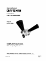
Owner's Manual
CRAFTSMAN
8.5 Horse Power
CHIPPER-SHREDDER
Model No.
247.77588O
CAUTION: Before using this product,
read this manual and follow all Safety
Rules and Operating Instructions.
Sears, Roebuck
Printed in U.S.A.
and Co., Hoffman
Estates,
IL 60179, U.S.A.
770-1228A
(3/98)
Content
Page
Content
Page
Warranty Information
2
Service & Adjustment
14
Safe Operation Practices
3
Off-Season Storage
16
Assembly
5
Trouble-Shooting
17
Operation
8
Repair Parts
18
Maintenance
11
One-Year Warranty
on Craftsman Chipper-Shredder
For one year from the date of purchase, when this Craftsmanchipper-shredderis maintained, lubricated,and
tuned up accordingto the operatingand maintenance instructionsin the owner's manual, Sears willrepair, free of
charge, any defect in material or workmanship.
This warrantyexcludes blades, chipperblades, flails, air cleaners, spark plugs, catcher bags and tires whichare
expendable parts and become worn dudng normal use.
If this chipper-shredderis used for commercialor rental purposes, this warranty appliesfor only 30 days from the
date of purchase.
WARRANTY SERVICE IS AVAILABLE BY CONTACTING THE NEAREST SEARS SERVICE CENTER IN THE
UNITED STATES. THIS WARRANTY APPLIES ONLY WHILE THIS PRODUCT IS IN USE IN THE UNITED
STATES.
This warranty gives you specific legal rights, and you may also have other rights which vary from state to state.
Sears, Roebuck and Co., D/817WA, Hoffman Estates, II 60179
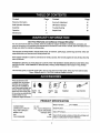
These accessories were
available when the chippershredder was purchased.
They are also available at
most Sears retail outlets, and
service centers. Most Sears
stores can order repair parts
for you when you provide the
model number of your
Craftsman chipper-shredder.
Spark
Plug
Air
Filter
Engine Gas
Oil
Can
Stabilizer
Tow HitchKit
PRODUCT SPECIFICATION
Model Number ............ 247.775880 ..........................
HORSEPOWER:
CRANKCASE CAPACITY:
FUEL TANK CAPACITY:
SPARK PLUG:
GAP
TIRE PRESSURE
8,5 H.R
26oz. SAE 30 ENGINE OIL
Serial Number ...........................................................
4 Quart (UNLEADED)
Champion (N4C)
.030
24 PSI
Date of Purchase ......................................................
Record both serial number and date of purchase and
keep in a safe place for future reference.
2
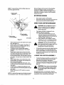
This symbol points out important safety instructions which, if not followed, could endanger the personal safety and/or property of yourself and others. Read and follow all instructions in this manual before
attempting to operate your chipper shredder. Failure to comply with these instructions may result in personal injury.When you see this symbol-heed its warning.
Your chipper-shredder was built to be operated according to the rules for safe operation in
RAN P_I=R- this manual. As with any type of power equipment, carelessness or error on the pert of the oper..........
ator can result in serious injury. If you violate any of these rules, you may cause serious
injury to yourself or others.
,_
]
/
/
/
/
J
to cause cancer, birthdefects or other reproductiveharm.
WARNING: The Engine Exhaust from this product containschemicalsknownto the State of California
GENERAL
OPERATION
Read thisowner's guidecarefully in itsentirety before
attemptingto assemble thismachine. Read,
understand,and follow all instructionson the machine
and in the manual(s) beforeoperation. Be completely
familiar with the controlsand the proper use of the
machine before operating it. Keep thismanual in a
safe place for future and regular reference and for
orderingreplacement parts.
Your chipper-shredderis a powerful tool, not a
plaything. Therefore, exercise extreme cautionat all
times. Your unit has been designed to performtwo
jobs; to chipand shred vegetation found in a normal
yard. Do not use itfor any other purpose.
Never allow children under age 16 to operate the unit.
Children 16 years and older shouldonlyoperate the
unit underclose parental supervision. Only
responsible individualswho are familiar with these
rules of safe operationshouldbe allowedto use your
unit,
Keep the area of operation clear of all persons,
particularlysmall children and pets. Stop the engine
when they are in the vicinityof the unit. Keep work
area clean and clear of branches or obstacleswhich
could cause you to stumbleor fall.
When feeding material intothisequipment, be
extremely carefulthat pieces of metal, rocks,bottles,
cans or other foreign objects are not included.
Personal injuryor damage to the machine could result.
Always wear safety glasses or safety goggles, during
operationand while performingan adjustmentor
repair, to protect eyes from foreign objects that may be
thrownfrom the machine.
Wear sturdy, reugh-soled work shoes and closefitting
slacks and shirt. Shirt and slacksthat coverthe arms
and legs and steel-tood shoes are recommended. Do
notwear loose fitting clothes or jewelry and secure hair
so it is above shoulder length. They can be caughtin
moving parts. Never operate a unit in bare feet,
sandals or sneakers. Wear glovss when feeding
matedal in the chipper chute or shredder hopper.
Never placeyour hands, feet, or any part of your body
intothe shredder hopper,chipper chute, discharge
opening, or near any moving part while the engine is
running. Keep clear of the discharge opening at all
times. If it becomes necassary to push matedal into
the chipper chute or shredder hopper, use a small
diameter stick, NOT YOUR HANDS.
If it is necessary for any reasonto unclogthe feed
intake or discharge openingsor to inspector repair any
part of the machine where a movingpart can come in
contact with your body or clothing,stop the machine,
allow it to cool,disconnectthe spark plug wire from the
spark plug and move it away from the spark plug
before attemptingto unclog, inspector repair.
Do not operate unitwhile underthe influence of alcohol
or drugs.
The machine shouldonly be operated on a level
surface. Never operate your uniton a slippery,wet,
muddyor icy surface. Keep yourwork area clean and
clear of branches or obstacles which could cause you
to stumbleand fall. Do notoverreach. Maintaining
properfooting and balance is essentialto preventing
accidents.
Do notallow an accumulationof processed material to
build up in the discharge area as thiswill prevent
properdischarge and can resultin kick-backfrom the
chipper chute.
Keep your face and body backfrom chipper chute to
avoid accidental bounce back of any material.
Do nottransport machine while engine is running.
If the cutting mechanism stdkesa foreign objector if
your machineshouldstart making an unusual noise or
vibration, immediately stop the engine and allowthe
machine to come to a complete stop. Disconnectthe
spark plugwire and move it away from the spark plug.
Take the following steps.
a. Inspect for damage.
b. Repair or replace any damaged parts.
o. Check for any loose partsand tighten to assure
continuedsafe operation.
Never attempt to attach or remove catcher bagwhen
engine is running. Shut the engine off and wait for the
impeller
tocome
toacomplete
stop.Theimpeller
continues
torotate
for a few seconds after the engine
is shut off. Never place any part of the body in the
impeller area untilyou are sure the impeller has
stopped rotating.
Muffler and engine become hotand can cause a bum.
Do not touch.
Do not allow leaves or other debris to build-upon
engine's muffler. The debris couldignite and cause a
fire.
Do not attempt to shred or chip material larger than
specified in this manual. Personal injuryor damage to
the machine could result.
Do not operate engine if air cleaner or cover over
carburetor air-intake is removed, exceptfor
adjustment. Removal of such parts could create a fire
hazard.
Only use accessories approvedfor thismachine by the
manufacturer. Read, understand,and follow all
instructionsprovidedwith the approved accessory.
If situationsoccur which are not covered by this
manual, use care and goodjudgment. Contact your
dealer for assistance.
Keep discharge chute deflector, chipper chute door,
and all other guards and safety devices in place and
operating propady.
Only operate unit in gooddaylight. Do notoperate unit
at nightor in dark areas where yourvision may be
impaired,
CHILDREN
Tragic accidents can occur if the operator is not alert to the
presence of small children. Children are often attracted to
the chippar-shredderand the chippingand shredding
activity. Never assume that children will remainwhere you
last saw them.
Keep childrenout of the work area and underthe
watchful eye of a responsibleadult other than the
operator.
Be alert and turnthe unitoff ifa child enters the area.
Never allow children underthe age of 16 to operate the
chipper-shredder,
SERVICE
least two minutes before refueling.
Replaco gasoline cap securely and wipe offany
spilledgasolinebefore startingthe engine as it
may cause a fire or explosion.
c. Extinguishall cigarettes, cigars, pipes and other
sourcesof ignition.
d. Never refuel unit indoorsbecause flammable
vaporswill accumulate in the area.
e. Never storethe machineor fuel container inside
where there isan open flame or spark suchas a
gas hotwater heater, space heater, clothesdryer
or furnace.
Never run your machine in an enclosed area as the
exhaustfrom the engine contains carbon monoxide,
which is an odorless, tastelessand deadly poisonous
gas.
To reducefire hazard, keep engine and mufflerfree of
leaves, grass, and other debris build-up. Clean up fuel
andoil spillage. Allowunit to cool at least 5 minutes
beforestoring.
Before cleaning, repairing,or inspecting,make certain
the impellerand all movingparts have stopped.
Disconnectthe spark plug wire and keepwire away
from spark plug to prevent accidental starting. Do not
use flammable solutionsto clean air filter.
Check the blade and engine mountingscrews at
frequent intervalsfor propertightness. Also visually
inspect bladesfor wear and/or damage (e.g., bent,
cracked). Replace with blades which meet original
equipmentspecifications.
Keep all nuts, bolts,and screws fight to be sure the
equipmentis in safe workingcondition.
Never tampar with safety devices. Check their proper
operationregularly.
After strikinga foreign object, immediatelystop the
engine, disconnectthe spark plug wire from the spark
plug, and thoroughlyinspectthe unit for any damage.
Repair damage before startingand operatingunit.
Do notalter or tamper with the engine's governor
setting. The governor controlsthe maximum safe
operatingspeed ofthe engine. Over-speeding the
engine is dangerous and will cause damage to the
engine and to other movingpartsof the machine.
b.
YOUR RESPONSIBILITY
Use extreme care in handlinggasolineand other fuels.
They are extremely flammable andthe vapors are
explosive.
a. Store fuel and oil in approved containers, away
from heat andopen flame, and outof the reach of
children. Check and add fuel before startingthe
engine. Never remove gas cap or add fuel while
the engine is running. Allow engine to coolat
Restrictthe use of thispower machine to
persons who read, understandand follow the
warnings and instructionsin this manual and on
the machine.
SAVE THESE INSTRUCTIONS
FUTURE REFERENCE
FOR
This unit is equipped with an internal combustion egine and should not be used on or near any unimproved forestcovered, brush-coveredor grass-covered land unlessthe engine's exhaust system is equipped with a spark arrester
meeting applicable local or state laws (if any). If a spark arrester is used, it shouldbe maintained in effective working
order by the operator.
In the State of California the above is required by law (Section 4442 of the California Public Resources Code). Other
states may have similar laws. Federal laws apply on federal lands. A sparkarrester for the muffler is available through
your nearest Sears Authorized Service Center (See the REPAIR PARTS section of thismanual.)
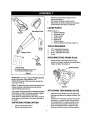
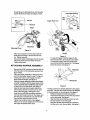
Remove all loose parts includingowner's
manual. See figure 1.
Roll chipper-shredderout of the canon.
Make certainall parts and literaturehave been
removedbefore the cartonis discarded.
LOOSE PARTS
Discharge Chute
Hopper*
(Refer to figure 1.)
a, Hopper Assembly
b. DischargeChute
c. Chipper Chute
d. Catcher Bag
e. Bottle of Oil
f. Safety Glasses
g. Owner's Manual (not shown in figure 1)
TOOLS
Bottle
of Oil
ChipperChute
1.
2.
3.
4.
REQUIRED
1/2"or AdjustableWrenches
7/16" or AdjustableWrenches
9/16" or AdjustableWrenches
Funnel
DISCONNECTING
Safety
Glasses
Catcher
SPARK
PLUG
Disconnect the spark plug wire and move it
away from the spark plug before assemblingthe
chipper-shredder. See figure 2.
Spark PlugWire
Bag
* The hopper is packed in the top insert
in your chipper-shredder carton.
Figure 1
IMPORTANT: This unitis shippedwithout gasoline
or oil in the engine, Al_erassembly, see
OPERATION sectionof this manual for proper fuel
and engine oilfill-up.
NOTE: To determine rightand left hand sides of your
chipper-shredder, stand behind the unit with the
engine farthest away from you.
Yourchipper-shredderhasbeen completelyassembled
at the factory, exceptforthe hopperassembly,chipper
chute,discharge chuteand the catcherbag.
These parts are shippedloosein the carton. A pairof
safety glasses and a bottle ofoil are also includedin
the canon.
UNPACKING FROM CARTON
Cut the corners of the canon.
Remove all packing inserts.
Figure 2
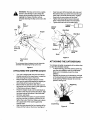
ATTACHING
DISCHARGE
CHUTE
Remove the wing knobs from each side of the
discharge opening on the chipper-shredder.See
figure 3.
Using two 7/16" wrenches, remove hex locknut,
two spacers, and the bex bolt fromtop of the
housingassembly. For easy assembly,do not
remove the second spacer from the hex bolt.
Place the discharge chute in positionon the
dischargeopening. Inserthex boltand spacer
through hinge on dischargechute and housing
(spacer fits inside of hinge). See figure 3 inset.
Hex Nut
--Hex
Spac_er_-J-_
Inlet Guide Opening
Hopper Pivot Door
Bolt
Hinge
Hopper
He_
Nut
\
Wing
Dischargl
Inlet
Guide
Figure 3
Place second spacer over hex boltinsidethe
other part ofthe hinge. Secure with hex lock
nut. Tighten securely.
Secure both sides of dischargechute to housing
using wing knobs that you earlier removed.
Tighten wing knobs.
ATTACHING
HOPPER
ASSEMBLY
Remove the 8-3/8" long hex boltand the hex nut
from the bottomof the inlet guide opening. See
figure 4 inset.
Place the hopperassembly on the ground and
hold it in the positionshown in step 1 in figure 4.
Holdingthe hopper, pushhopper pivotdoor
down insidethe hopper. See figure 4.
Slide the hopperassemblytowards the chippershredder housingso that the upper guide on the
hopper assemblyslides under the stop washer
on each side of the inletguide, See figure 4.
Align the two holes(one on each side) of the
lower hopperwith the two holes (one on each
side) ofthe inletguide. See figure 4 inset.
insert the hex bolt(that you earlier removed)
from the leftthroughthe holeon the hopper and
the inletguide. Insertthe hex nut onto the bolt
from the otherside. See figure 4 inset.
Tighten the bolttillthe lock nut is engaged.
Make sure to remove sideplay from the bolt, but
the hoppershouldbe able to pivot.
1.
Hopper
Figure 4
To raise the hopper, holdthe hopperby the
hand-holdand liftit up till it clicksintoposition.
To Iowerthe hopper, hold the hopperby the
hand-holdand pullthe release bar. The hopper
shoulddrop down. See figure 5.
Release Bar
Figure 5
The flap controlrod is already attached to the hopper
at the top. The other end of the rod has to be attached
to the stop washer on the inletguide. See figure 6.
Raise the hopper tillit clicksinto position.
Unscrewthe shoulder boltfrom the stop washer
on the inlet guide. See figure6.
Align the loose end of the flap controlrodwith
the stop washer on the inletguide.
Slidethe shoulder boltthroughthe opening in
the flap controlrod. Secure tightly.See figure 6.
&
WARNING; This flap controlrod is a safety
device to hold the flap in place inside the
hopper while shreddingbranches. Do not
operate the chipper-shredderwithout
properly attachingthis flap controlrodto the
unit.
Hex
Nut*
Stop
Washer*
Chipper
Chute
//
=ettI /
Insertone each of the hex bolts,lock nuts,and
flat washers (that you earlier removed) through
each hole in the chute and the brace.Tighten
these boltsto secure brace to the chute.
Tightenboltssecuringthe brace tothe lower
frame. These boltshad been removedeadier.
Tighten the three nuts on the weld studs.
io_
\
Washer
Cupped
Weld Stud
Weld Stud
\
Washer
Attach flap
control rod
here
Chu_
Bmce
Figure 7
Flap Control
Rod
ATTACHING
* Do not remove these hardware from the inlet guide
assembly while attaching the flap control rod.
Figure 6
ATTACHING
THE CHIPPER
CHUTE
Your unitis shippedwith one end of the brace
already securedto the lower frame. Loosen the
boltssecuringthe brace to the frame.
Remove the three cupped washers and hex
nuts from the weld studsbeside the opening on
the left side of the housing.See figure 7.
Remove the two sets of hex bolt, lock nut, and
fiat washer from the two holes on the upper end
of the brace as shown in figure 7.
Place the chipperchute over the weld studs so
the sloton the chute istowardsthe bottom.Align
the three holesat the bottomof the chute with
the three weld studs.
Secure with the three pairsof cupped washers
and hex nutsthat you earlier removed. Do not
tighten the nuts at this time. Make sure to place
the cupped side of the washer againstthe
chipperchute.
Align the holes towardsthe front opening of the
chute with the holes on the brace. See figure7.
THE CATCHER
BAG
Your chipper-shredderisequipped with a catcher bag
to catch the shreddedmaterial.
To attach the bag, place the openingof the bag
over the chute deflectorand the chute flange.
Make sure itcompletely coversthe chute
deflector.
Depress the plunger on the drawstring, and pull
on the drawstring until the bag is tight around the
chute opening. Release plunger to lock it into
position. See figure 8.
Plunger
Catcher Bag
Figure8
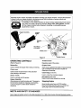
Read this owner's manual and safety rules before operatingyour chipper-shredder.Compare the illustration
in figure 9 with your chipper-shredderto familiarize yourselfwith the locationof various controlsand
adjustments.Save this manual for future reference.
_
eyes, which can result in severe eye damage. Always wear safety glasses provided
with the chipper-shredderbefore chippingor shredding, or while performingany
he operation ofrepairs.
any chipper-shredder can result in foraign objects being thrown into the
adjustmentsor
Release
Bar
Rear Wheel
Lock Lever
Figure 9
OPERATING CONTROLS
Throttle Control
(Refer to Figure 9,)
Regulates speed of the engine.
Release Bar
Chipper Chute
Used to release the hopper when raisingor lowering.
Allows bulkyvegetation like stalksor heavy branches
upto 3" diameter to be fed intothe impellerfor
chippingand shredding.
Choke Lever
Used to enrich the fuel mixturein the carburetor
when startinga cold engine.
Used to collectthe shredded material.
Starter Handle
Used to manually start the engine.
Hopper Assembly
Allowsleaves and small branches upto 1"diameterto
be fed intothe impellerfor chippingand shredding,
Lowerthe hopper to collectraked material for
shredding.
MEETS ANSI SAFETY
Catcher Bag (not shown)
Rear Wheel Lock Lever
Used to lock the rear wheels from moving.
Stopping Engine
Move throttlecontrollever to STOP position.
Disconnectspark plugwire and move away from
spark plugto preventaccidental starting.
STANDARDS
Sears chipper-shredders conform tothe safetystandardB 71.6 -1990 ofthe American National Standards Institute.
8
shredder, again
refer usingyourchipperto the safety rules on
WARNING:
Before
pages 3 and 4 of this manual. Always be
careful.
Oil (Packed with unit)
Only use high quality detergent oil rated with
API service classification SF, SG or SH. Select
the oil's viscositygrade accordingto your
expected operating temperature. Followthe
chart below.
5W30
32°F
I
I
NOTE: Do not overfill. Oil bottle packed with unit
contains 26 oz. of oil.
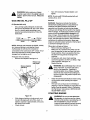
Gasoline
GAS AND OIL FILL-UP
Colder _
Add oil if necessary. Replace dipstick and
tighten.
Warmer
SAE 30
NOTE: Although multi-viscosity oils (5W30, 10W30,
etc.) improve starting in cold weather, these
multiviscosity oils willresult in increasedoil
consumptionwhen used above 32°F. Check the oil
level more frequently to avoid possible engine
damage from runninglow on oil.
Fill engine with oil as follows.
Remove oilfill dipstick. See figure 10.
Remove cap
and fill gas
WARNING: Experience indicatesthat alcohol
blended fuels (called gasohol or using ethanol or
methanol) can attract moisture which leads to
separationand formationof acids duringstorage.
Acidicgas can damage the fuel system of an engine
whilein storage. To avoid engine problems, the fuel
system should be emptied before storage for 30
daysor longer. Drain the gas tank, start the engine
and letit run until the fuel linesand carburetor are
empty. Use fresh fuel nextseason. See STORAGE
instructionsfor additionalinformation.Never use
engine or carburetor cleanerproducts in the fuel tank
or permanent damage may occur.
Fill gas tank with gas as follows.
Remove fuel cap. See figure 10.
Make sure the container (from which you will
pour the gasoline) is clean and free from rust or
foreign particles. Never use gasoline that may
be stale from long periods of storage in the
container.
Fill fuel tank with clean, fresh, lead-free
automotive gasoline. DO NOT use Ethyl or high
octane gasoline. See figure 10.
Replace fuel cap.
Remove dipstick
WARNING:
of top of fuel tank
Do not
to preventspillsand
fill closer than 1/2
toinch
allowfor fuel expansion. If gasolineis
accidentlyspilled,move chipper-shredder
away from area of spill.Avoid creatingany
sourceof ignitionuntilgasolinevaporshave
disappeared.
\
Check the fuel level periodically to avoid running
out of gasoline while operating the chippershredder.
If the unit runs out of gas as it is shredding or
chipping, it may be necessary to unclogthe unit
before itcan be restarted. Refer to "Removing
the Flail Screen" instructionsin SERVICE AND
ADJUSTMENT section.
STARTING
Figure 10
With chipper-shredder on level ground, use a
funnel to fillengine with oil to FULL mark on
dipstick.Capacity is approximately 26 ounces.
Be careful not to overfill.
Check oil level.
&
ENGINE
WARNING: Be sure no one other than
the operator is standingnear the chippershredderwhilestartingor operatingthe unit.
Do not operate thischipper-shredder
unlessthe chutedeflectorhas been properly
installedand securedwith hand knobs.
NOTE:TOprevent
the unit fromsliding,place your
foot firmlyagainst the tire.
flails and fingers which are part of the shredding
mechanism falling intoplace, and shouldbe
expected./n addition,the flails and fingers will be
noisyafter the engine is started, untilthe impeller
reaches furl speed.
1. Attach spark
plug wire --
STOPPING
ENGINE
Move starter switch to OFF position.
Disconnect spark plugwire and move away from
spark plug to preventaccidentalstarting.
\
USING YOUR CHIPPER-SHREDDER
A
The chipper-shredderis designed for two
different methodsof operation.
a. Leaves and small branches up to 1/2"
diameter (maximum) can be fed intothe
hopperassembly when it is in the raisedor
lowered position.See figure 12.
b. Bulky material,such as stalksor heavy
branches,up to 3" in diameter shouldbe
fed intothe chipperchute. See figure 12.
2. Place throttle
in Fast Position
3. Move choke
to "on" position
WARNING: Do not attempt to shred or
chip any matedal otherthan vegetation
found in a normal yard (i.e., branches,
leaves, twigs,etc.).
4. Pull rope
Figure 1t
Attach spark plug wire and rubber boot to spark
plug. See figure 11.
Place throttle in FAST position. See figure 11.
Move choke lever to CHOKE position (in the
direction of the arrow) as shown.
If restarting a warm engine after a short
shutdown, move choke lever to =No Choke"
position.
Grasp starter handle and pull ropeout slowly
untilengine reaches startof compressioncycle
(rope willpull slightlyharder at this point).Let
the rope rewind slowly. Pull ropewith a rapidfull
arm stroke. Let rope returnto starter slowly.See
figure 11.
When engine starts, move choke lever to half
choke positionuntil engine runs smoothlyand
then to No Choke position.
If engine fails to start after three pulls, move
choke lever to No Choke positionand pullstarter
rope again.
Ifengine rims, but does not continue to run,
move choke lever to Full Choke positionand pull
rope again.
Move choke lever to OFF positionas engine
warms up.
A
WARNING: Do not put material larger
than is specifiedinto the hopper, and/or into
the chipperchute. Personal injuryor
damage to the machinecould result.
If it becomes necessaryto pushmaterialintothe
chipper-shmdder,use a small diameter stickNOT YOUR HANDS. The stickshouldbe small
enoughthat itwill be ground up if it gets intothe
impellerassembly.
LOWER THE HOPPER
ASSEMBLY
To lowerthe hopper assembly, use one handto
grasp the hand-hold at the top of the hopper
assembly and lift slightly.See figure 5.
Pullup on the release bar, and lower the hopper
assembly to the ground.Release the bar. See
figure 5.
A
WARNING: Never remove chute deflector
tillthe unit has completely stopped.Never
shut offthe engine until all chipping is
completed.
For best performance, it is important to keep the
shreddingblade and the chipper blades sharp. If the
composition of the material being discharged
NOTE: A noise will be heard when finding the start of
the compression cycle. This noise is caused by the
10
changes
(becomes
stdngy,etc.) or if the rate at which
A
the material is discharged slows down considerably, it
is likely that the shredding blade and/or chipper
blades are dull and need to be sharpened or
replaced. Refer to Service and Adjustments section.
IMPORTANT: There is a flail screen located inside
the housing in the discharge area. If the flail screen
becomes clogged, remove and clean as instructed in
the Service and Adjustments section.
WARNING: The chipper-shredder
discharges materialswith considerable
velocity.Keep away from the area aroundthe
dischargechute. Always stop the engine and
disconnectspark plugwirewhen removingor
attachingthe bag,changing containers, or
removingtheshreddedmatarial.Wear safety
glassesand gloveswheneverusingyour
chipper-shredder.
Shred materialupto 1/2 inch in diameter
/
Chip material upto 3 inches
in diameter
Catch shredded material
in catcher bag
Lower the hopper to collect
raked material for shredding
Figure 12
GENERAL
RECOMMENDATIONS
Always observe safety ruleswhen performing
any maintenance.
The warranty on this chipper shredderdoes not
cover items that have been subjectedto operator
abuse or negligence.To receive full value from
the warranty, operator must maintainthe chippershredder as instructedin this manual.
Some adjustments willneed to be made
periodicallyto maintain your unitproperly.
All adjustments in the Service and Adjustments
sectionof this manual shouldbe checked at least
once each season.
Followthe maintenance schedule given below.
Periodicallycheck all fasteners and make sure
these are tight.
A
WARNING: Always stop the engine and
disconnect the spark plugwire before
performingany maintenance or adjustments.
Never remove discharge chute tillthe
engine has completelystopped.
CLEANING
Clean the chipper-shredderby runningwater
from a hose through the hopper assembly and
chipperchute with the engine running.Allowthe
chipper-shredderto dry thoroughly.
Wash the bag pedodicallywith water. Allow todry
thoroughlyin the shade. Do not use heat.
ENGINE
MAINTENANCE
Engine Oil
Only use high qualitydetergent oilrated with API
service classification SF, SG or SH. Select the
oil's viscosity grade according to your expected
11
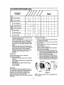
CUSTOMER RESPONSIBILITIES
o
MAINTENANCE
sc. oo,
_
_
..,P
o,O
{
e,_P
_3
=_
o
,v.C o,TEs
Oil pivot points
0
a.
Clean shredder
_
Check engine oil
,,,
Change engine oil
<_
Service air cleaner
ILl
Clean engine
_
Reset spark plug
_
Clean muffler
operatingtemperature. Refer to page 9 ofthis
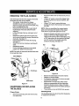
To Service Air Cleaner:
manualfor viscositychart.
The four-cycle engine of your chipper-shredder
willnormallyconsumesome oil. Therefore,
check engine oil level regularly approximately
1.
avery five hours of operationand before each
usage.
Stop engine and wait several minutesbefore
checkingoil level. With engine on level ground,
the oil mustbe to FULL mark on dipstick.
Change engine oilafter the first five hours of
operation,and every twenty-fivehours
thereafter.
2.
3.
To Drain Oil
Drain oilwhile engine is warm. Followthe
instructionsgiven below.
Remove oil drain plug. Catch oil in a suitable
container.
When engine isdrained of all oil, replace drain
plug securely.
Refill with fresh oil. Refer to GAS AND OIL
FILL-UP section.
Replace dipstick.
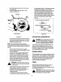
Service pre-cleaner after every 25 hours of use,
or at least once a season.
Service filterevery 100 hours of use, or at least
once a season.
Service pre-cleanerand filtermore often under
dusty conditions.
Remove wing nut and cover.
Slide pre-cleaner offfilter. Clean the insideof
base and cover thoroughly.
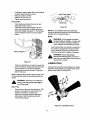
Clean pre-cleanaras follows:(See figure 13.)
a. Wash in water and detergentsolution,and
squeeze(donottwist)untilalldirtisramoved.
b. Rinse thoroughlyin clear water.
c. Wrap ina cleanclothand squeeze (donot
twist) untilcompletelydry,or allowtoair dry.
d. Saturatewithengineoiland squeeze(don't
twist) to distributeoiland removeexcessoil.
Foam Filter --
Air Cleaner
The air cleaner prevents damaging dirt, dust,etc.,
from enteringthe carburetorand being forced into
the engine and is importantto engine life and
performance.The air cleaner consistsof a precleaner or foam filter, and a paper filter.
Never run the engine withoutair cleaner completely
assembled.
12
L
Base
Wing Nut--
PaperFilter
Figure 13
NOTE: If the pre-cleaner is torn or damaged in any
way, replace it.
Ifnecessary,
replace
paper filter(do not attempt
to clean). Installnew filter on base.
Slide pre-cleaner over filter.
Install cover and wing nut.
Tightenwing nut securely.
' Feeler (
Clean Engine
Plug
Clean engine periodically. Remove dirt and
debris with a clothor brush.
Frequently remove grass clippings, dirt and
debris from cooling fins,air intake screen and
levers and linkage. See figure 14. This will help
ensure adequate cooling and correct engine
speed.
Figure 15
NOTE: Do not sandblast spark plug. Spark plug
should be cleaned by scrapingor wire brushing and
washing witha commercialsolvent.
Muffler
A
WARNING: Do not operate the chippershredder without a muffler, or tamper with
the exhaust system. Damaged mufflersor
spark arresterscould create a fire hazard.
Inspect periodically, and replace if necessary. If
your engine is equipped with a spark arrester
screen assembly, remove every 50 hours for
cleaning and inspection. Replace if damaged.
Clean cooling
&
Figure 14
WARNING: Always stop engine,
disconnect spark plug wire, and move it
away from spark plug before performingany
adjustmentsor repairs.
LUBRICATION
Yearly or every 25 hours, whicheveroccursfirst,
remove the blower housing and clean the areas
shownin figure 14 to avoidoverspeeding,
overheatingand engine damage. Clean more
often if necessary.
Lubricate the pivot points on the release bar, hopper
assembly, chute deflector and chipper chute once a
season using a light oil. See figure 16
NOTE: Cleaning with a forceful spray of water is not
recommended as water could contaminatethe fuel
system.
nearby areas may
WARNING:
Temperature
exceed 150
of muffler
° F(65°C).
and
Avoid these areas,
Spark Plug
Clean the spark plug and reset the gap to .030"
at least once a season or every 50 hours of
operation. See figure 15. Spark plug
replacement is recommended at the start of
each season. Refer to engine parts list for
correct spark plug type.
Figure 16: Lubrication
13
Chart
14
REMOVING
Remove the flail screenas instructedin previous
section.
Using a 1/2"wrench, remove the chipperchute
by removingthree hex nuts and washers. See
figure 17,
Using a 7/16" wrench, remove the brace
(holdingthe chute to the frame) by removingthe
hex bolts.
THE FLAIL SCREEN
If the discharge area becomes clogged, remove the
flailscreen and clean area as follows.
Stop engine, make certain the chippershredder has come to a complete stop and
disconnect spark plug wire from the spark plug
before unclogging the chute.
Remove the two hand knobs on each side of
the dischargechute (also called the chute
deflector).
Liftthe dischargechute up, and keep it out of
the way.
Remove two hairpinclips from the clevis pins
whichextend throughthe housing.Remove the
clevispins, See figure 17.
Pullthe flail screen from inside the housing.
See figure 17.
Clean the screen by scrapingor washingwith
water.
Reinstallthe screen.
Put the discharge chute back to its original
positionand tighten the hand knobs.
NOTE: When re-assembling,the cupped washer
goes on the slot towardthe bottom of the chipper
chute with the cupped side against the chute.
Rotate the impeller assembly by hand untilyou
locate one of the two chipperblades in the
chipper chute opening. Remove the blade, using
a 3/16" allen wrench on the outside of the blade
and 1/2" wrench on the impeller assembly
(inside the housing). See figure 18.
Slot
Blade
NOTE: Be certain to reassemble the flail screen with
the curved side down.
Chute Deflector
Chipper Chute
Figure 18
Hex Nut,
Washer
Remove the other blade in the same manner.
Replace or sharpen blades.
If sharpening, make certain to remove an equal
amount from each blade.
Reassemble in reverse order. Make certain
bladesare reassembled with the sharpedge
facing the directionshownin figure 18 (sharp
edge isassembled toward the slottedopeningat
the bottom).
Torque boltsand nutsto 250-350 inch-pounds.
Hand Knobs
Figure 17
SHARPENING
THE BLADES
OR REPLACING
Chipper Blades
Disconnectspark plug wire and move it away
from spark plug.
Shredding
Blade
The shredding blade may be removed for sharpening
or replacement as follows.
15
Disconnect
sparkplug wire and move it away
causedamage to theunit.The blade can be tasted
for balance by balancing iton a roundshaft
screwddveror nail. Removemetalfrom the heavy
side untilitis balancedevenly.See figure20.
When reassemblingthe blade, tightencenter
boltto between 550 and 650 inch-poundsand
the two outer boltsto between 250and 350 inchpounds, or lackingtorque wrench, tighten
securely.
from spark plug.
Lower the hopper assembly. Block up the
housing.See figure 19.
Weld Bolt
Allen
Screw
1. insertscrewdriver throughhole
Pipe
d/
2. Bladeshouldbe parallelto ground
Screv_
Driver\
Blade
i
I -Ground
Torque Wrench
Figure 19
Figure 20
ADJUSTING CARBURETOR
Remove the six hex lock nuts and lock washers
from the housingweld boltsusing a 1/2"wrench.
Separate the chipper-shredderintotwo halves.
Remove the back-up plate.
NOTE: When reassembling, make certain the
embossed tab faces inward towards the impeller, and
opening on the back-up plate is toward the bottom of
the unit.
Remove the two hand knobs and cupped
washers whichsecure the chute deflector. Raise
the chute deflector.
Inserta 1/2" or 3/4" diameter pipethrough the
flail screen intothe impellerto keep itfrom
turning,or remove the flail screen and insert a
piece of wood (2 x 4) intothe chute opening.
Remove the two outside screwson the blade,
using a 3/16" allenwrench and a 1/2"wrench.
Remove the blade by removing the center bolt,
lockwasher and fiat washer.
A
WARNING: If any adjustmentsare made to
the engine whiletheengine isrunning(e.g.
carburetor),keep clear of all moving parts.
Be careful of heated surfaces and muffler.
The carburetor has been pre-set at the factory and
shouldnot requireadjustment.However, if your
engine does not operate properlydue to suspected
carburetor problems,take yourchipper-shredderto
your nearest SEARS service center.
ENGINE SPEED
The engine speed on your chipper-shredderhas been
set at the factory. Do not attempt to increase engine
speed or it may result in personal injury. If you believe
the engine is running too fast or too slow, take your
chipper-shredder to the nearest SEARS service
center for repair and adjustment.
TIRES
,_
the
blade to avoid
contacting
theremoving
weld bolts
WARNING:
Use caution
when
on the housing.
Recommendedoperating tire pressure is 24 p.s.i.
(sidewallof tire may give tire manufacturers
recommendedpressure).Equal tire pressureshould
be maintained on both tires.
When sharpening the blade, follow the original
angle of grind as a guide. It is extremely
important that each cutting edge receives an
equat amount of grinding to prevent an
unbalanced blade.
An unbalanced blade will cause excessive
vibration when rotating at high speeds and may
beadsmay
cause
tire/rimassembly
toburstwith
WARN
ING:
Excessive
pressurewhenseating
force sufficient
tocause serious injury.
16
Prepare your chipper-shredderfor storageat the end
of the season or if the unitwillnot be used for 30 days
or more.
A
products in the fuel tank or permanent damage
may occur.
Use fresh fuel next season.
WARNING: Never store machinewith fuel
in the fuel tank inside of building where
fumes may reach an open flame or spark,
or where ignitionsourcesare present such
as hot water end space heaters, furnaces,
clothes dryers, stoves, electricmotors,etc.
NOTE: Fuel stabilizer is an acceptable alternativein
minimizing the formation of fuel gum deposits during
storage.
Add stabilizerto gasoline in fuel tank or storage
container.
Always follow the mix ratiofound on stabilizer
container.
Run engine at least 10 minutesafter adding
stabilizerto allow the stabilizerto reach the
carburetor.
Do not drain the gas tank and carburetorif using
fuel stabilizer.Drain all the oilfrom the
crankcase (this shouldbe done after the engine
has been operated and is stillwarm) and refill
the crankcase with fresh oil.
If you have drainedthe fuel tank, protectthe
inside of the engine as follows.
Remove spark plug,pour approximately 1/2
ounce (approximatelyone tablespoon) of engine
oil intocylinderand crank slowlyto distributeoil.
Replace spark plug.
A yearly check-up by your local Sears service center
is a good way to make certain your chipper-shredder
will provide maximum performance for the next
season.
CHIPPER-SHREDDER
Clean the chipper-shredderthoroughly.
Wipe unitwith an oiled rag to prevent rust (use a
light oil or silicone).
ENGINE
IMPORTANT; It is importantto prevent gum deposits
from forming in essentialfuel system parts such as
carburetor,fuel filter,fuel hose, or tank during
storage. Also, experience indicatesthat alcohol
blendedfuels (called gasohol or using ethanol or
methanol) can attractmoisturewhich leads to
separationand formationof acids duringstorage.
Acidic gas can damage the fuel system of an engine
while in storage.
OTHER
Do not store gasolinefrom one season to
another.
Replace yourgasoline can if your can startsto
rust. Rust and/or dirtin your gasolinewill cause
problems. Store unit in a clean, dry area. Do not
store next to corrosivematerials, such as
fertilizer.
Drain the fuel tank.
Start the engine and let it run untilthe fuel lines
and carburetor are empty.
Drain carburetor by pressingupward on bowl
drain which is located belowthe carburetor.
Never use engine or carburetorcleaner
NOTE; ff storing in an unventilated or metal storage
shed, be certain torustproofthe equipment by coating
with a light oil or silicone.
17
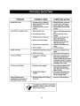
PROBLEM
POSSIBLECAUSE
CORRECTIVEACTION
Engine
failstostart
1.Fueltankempty,
orstalefuel
2. Spark plug wire disconnected
3. Faulty spark plug
4. Throttlecontrolnot in correct
position
1. Fill tank with clean, fresh fuel
2. Connect wire to spark plug.
3. Clean, adjustgap or replace.
4. Move throttlecontrolto FAST
position
Loss of power; operationerratic
1. Spark plug wire loose
1. Connect and tighten spark plug
wire
2. Move choke lever to OFF
position
3. Clean fuel line;filltank with
clean, fresh gasoline.
4. Disconnect fuel lineat
carburetorto drain fuel tank.
Refillwith fresh fuel.
5. ContactyourSEARS service
center.
6. Serviceaircleaner.
2. Unit runningon Choke
3. Blocked fuel line or stale fuel
4. Water or dirt in fuel system
5. Carburetor out of adjustment
6. Dirty air cleaner
Engine overheats
1. Carburetornot adjusted properly
2. Engine oil level low
1. Contact your SEARS service
center
2. Fill crankcase with properoil
Too much vibration
1. Loose parts or damaged
impeller
1. Stop engine immediatelyand
disconnectspark plug wire.
Tighten all bolts and nuts.Make
all necessary repairs. If vibration
continues, have unit serviced by
e SEARS service center.
Unit does not discharge
1. Dischargechute clogged
1. Stop engine immediatelyand
disconnectspark plug wire.
clean flailscreen and inside of
blower housing.
2. Stop engine immediatelyand
disconnectspark plugwire.
Remove lodgedobject.
2. Foreignobject lodgedin
impeller
Rate of discharge slows
considerablyor compositionof
discharged material changes
1. Shreddingblade and/orchipping
blade dull
1. Sharpen or replace blade(s)
For repairs beyond the minor adjustments
listed above, please contact your nearest
SEARS service center.
18
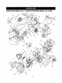
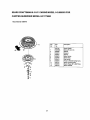
SEARS
CRAFTSMAN
8.5 H.P. CHIPPER-SHREDDER
MODEL 247.775880
5
21
14
13
18
33
29
6
12
97
52
74
56
63
65
85
88
80
79
91
19
Key
No
Part No
-1
2
3
770-1228A
11480
681-0118
681-0144
4
710-0542
710-0607
710-3256
7
8
9
712-0429
712-3027
714-0104
10
11
12
13
14
15
16
17
18
715-0129
726-0106
726-0135
728-0175
732-0546
732-0629
735-0127
735-0651
736-0119
19
20
21
22
23
124
,25
126
27
28
738-0137A
738-0946
747-0531A
747-0747
747-1124
747-1125
781-0492A
781-0633
781-0698
781-0715
Description
Key
No
PartNo
Owner's Manual
49
726-0214
Stop Washer
50
51
52
53
734-0255
750-0793
712-3027
714-0149B
55
56
57
58
59
720-0170
710-0805
781-0510B
736-0366
734-1845
61
63
65
67
68
69
736-0170
681-0117-0689
710-0157
70
71
72
73
74
75
76
736-0119
681-0030
742-0571
781-0457-0637
681-0094
781-0735
715-0166
78
79
80
82
83
85
87
88
89
710-1054
710-3008
681-0004A-0689
710-0825
726-0211
711-0835
719-0329
711-0833B
710-1254
90
91
736-0217
736-0247
92
93
94
95
96
97
98
732-0306
7360117
714-0104
711-1304
736-0160
734,-1797
726-0299
99
100
747--0982
764-0501
Inlet Guide Assembly
Arm Bracket Assembly
Hex Flange Bolt: 5/16-18 x
8.375" (Gr.5)
Hex Washer Head Self-Tapping Screw: 5/16-18 x 0.5"
Button-Head Screw 1/4-20 x
0.5"
Lock Nut: 5/16-18
Hex Flange Lock Nut: 1/4-20
Internal Cotter Pin
Spiral Pin
Cap Nut
Speed Cap Nut
Pop Rivet
Torsion Spring
Hopper Door Spring
Rubber Washer
Hopper Flap
Lock Washer
Shdr. Scr: .340 x .285 x 1/4-20
Shdr. Scr: .56 x .165 x 5/16-18
Rel. Rod: 5/16" dia.
Hopper Door Rod
Flap Retaining Rod
Flap Retaining Bail
Hopper Pivot Door
Chute Flap Strip
Hopper Lock Bracket
Shredder Plate
29
30
31
32
781-0752
781-0754-0689
781-0755-0689
738-0813
Flap Mounting Bracket
Upper Hopper
Lower Hopper
Shredder Axle
33
37
38
39
40
41
731-1899
710-0751
736-0173
712-3027
749-1004
710-0106
Chipper Chute
Hex Bolt 1/4-20 x .625
Flat Washer .28 I.d. x .74 O.d.
43
44
45
48
712-3010
736-0242
735-0249
681-0068-0689
Flanged Lock Nut
Chipper Chute Support
Hex Scr. 1/4-20 x .625 (Gr. 2)
Hex Nut 5/16-18 Thd. (Gr. 5)
Bell Washer .345" I.d. x .88"
Shredder Chute Flap
Chipper Chute Assembly
2O
781-0490
712-0411
Description
Push Cap 5/8" dia,
Ai rVaIve
Chute Hinge Spacer
Hex Ctr. Lock Nut 1/4-20 Thd.
Internal Cotter Pin
Hand Knob
Hex Bolt 5/18-18 x 1.5"
Shredder Frame
Flat Washer 1,12 x ,64 x .120
Wheel Assembly
Special LockWasher
Flail HousingAss'y, -- Inner
Hex Bolt5/16-24 x ,75" Lg,
Engine,Tecumseh 143.988503
Chipper Blade
Hex Top Lock Nut 5/18-24
(Gr. 5)
Lock Washer 5/16" I.d.
impeller assembly
Shredder Blade
Shredder Screen
Discharge Chute Assembly
Retaining Clip
Spring Roll Pin
Flat Head Scr. 5/16-24 x .75"
Hex Bolt 5/16-18 x .75" (Gr. 5)
Flail Housing Ass'y. -- Outer
Hex Bolt 1/4-20 x 3.75"
U Nut 5/16-18
Clevis Pin
Flail Blade
Clevis Pin
Hex Patch Bolt 3/8-24 x 2.25"
(Gr.8)
Lock Washer 3/8"
Flat Washer .406" I.d. x 1.25"
Compression Spring
Flat Washer
Internal Cotter Pin
Axle Shaft
Flat Washer
Complete Wheel: Grey
Push Cap
Lock Rod
Shredder Bag
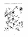
SEARS
CRAFTSMAN
CHIPPER-SHREDDER
8.5 H.P. ENGINE
MODEL
143.988503
FOR
MODEL 247.775880
4OO
3O5
310
35
2g0
757
87
7O
69
101
182
251
21
1t0
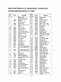
SEARS
CRAFTSMAN
CHIPPER-SHREDDER
Key
No.
--
Part No.
m
1
2
4
5
35385
27652
15
30699C
15A
30700
650494
33454
17
18
19
20
25
30969
29916
651028
34663
35319
26
28
30
35
38
37
36460
650561
30322
36283A
29826
29918
29216
38
40
40
29642
40011
40012
41
40009
40010
41
42
42
43
40013
45
36897
47
48
49
5O
60
651033
34034
36896
35375
33273A
65
69
70
650128
35262A
35376
71
72
75
40014
27888
35377
28582
35319
8.5 H.P. ENGINE
MODEL
MODEL 143.988503
247,775880
Description
Key
No.
Part No.
RPM Low 1700
80
31845
RPM High 3450 to 3750
Cylinder (Incl. 2 & 20)
Dowel Pin
81
82
83
30590A
35378
30588A
Oil Drain Extension
84
29193
ExtensionCap
Governor Rod (Incl. 15A &
15B)
Governor Yoke
86
87
89
90
650833
650832
32589
611090
Screw, 6-40 x 5/16"
Governor Lever
Governor Lever Clamp
Screw,TorxT-15, 8-32 x 3/8"
92
93
100
101
650880
650881
35135
610118
Speed Control Spring
Oil Seal
B_owerHousing Baffle
Screw, 1/4-20 x 5/8"
Lock Nut, 8-32
Crankshaft
102
103
651024
651007
110
119
120
35187
36448
36449
Screw, 10-32 x 3/4"
LockWasher
Lock Nut, 10-32
125
125
126
27878A
27880A
34035
Retaining Ring
126
34036
127
128
130
130A
130B
135
650691
650690
650694A
650273
651031
33636
139
140
33369
650836
149
149A
150
151
27882
35862
27881
32581
169
170
171
172
27896A
28423
28424
28425
173
173A
36675A
32446
174
178
650128
29752
182
184
30088A
33263
Piston, Pin & Ring Set (std,)
Piston, Pin & Ring Set (,010"
os)
Piston& Pin Assembly (std,)
Piston & Pin Assembly (.010"
os)
Ring Set (std,)
Ring Set (,010" os)
Piston Pin Retaining Ring
Connecting Rod Ass'y (incl.
47 & 49)
Connecting Rod Bolt
Valve Lifter
Oil Dipper
Camshaft (MCR)
Blower Housing Extension
Screw, 10-24 x 112"
Cylinder Cover Gasket
Cylinder Cover (Incl. 71, 75 &
80)
Crankshaft Bushing
Oil Drain Plug
Oil Seal
FOR
22
Description
Governor Shaft
Washer
Governor Gear Ass'y.
Governor Spool
Retaining Ring
Screw, 1/4-20 x 1-3/16"
Screw, 1/4-20 x 1-11/16"
Flywheel Key
Flywheel
Lock Washer
Flywheel Nut
Solid State Ignition
Spark Plug Cover
Solid State Mounting Stud
Screw, Torx "1"-15,10-24 x
15116"
Ground Wire
Cylinder
Cylinder
Exhaust
Exhaust
Head Gasket
Head
Valve (std.)
Valve (1/32" os)
Intake Valve (std.)
Intake Valve (1/32" os)
Washer
Belleville Washer
Screw, 5/16-18 x 2"
Screw, 5/16-18 x 518"
Screw, 1/4-20 x 9/16"
Resistor Spark Plug
Governor Gear Bracket
Screw, 10-24 x 1/2"
Valve Spring Cap
Valve Spring Cap
Valve Spring
Valve Spring Keeper
Breather Gasket
Breather Body
Breather Element
Valve Cover
Breather Tube
Breather Tube Grommet
Screw, 10-24 x 1/2"'
Nut & Lock Washer
Screw, 1/4-28 x 1"
Carburetor to Intake Pipe
Gasket
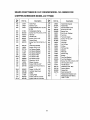
SEARS CRAFTSMAN 8.5 H.P. ENGINE MODEL 143.988503
CHIPPER-SHREDDER
Key
No.
Part No.
185
186
200
34707
34667
34677
203
204
206
207
31342
651029
610973
33878
209
215
223
650821
35882
650378
224
238
239
240
242
245
27915A
28820
27272A
37104
33267
33268
245A
250
251
260
35881
33269A
650513
36250
261
262
650788
29747B
264A
265
275
276
650802
33272B
34185B
31588
277
277A
650729
651036
FOR
MODEL 247,775880
Description
Key
No.
Part No.
Description
Intake Pipe
Governor Link
278
280
36908
36799A
Control Bracket (Incl. 19,203
& 204)
Compression Spring
Screw, Torx3"-10, 5-40 x 7/16"
281
282
285
287
33013
650760
35985B
29752
Heat Shield Spacer
Heat Shield
Starter Bubble Cover
Terminal
Throttle Link
Screw, 10-32 x 1/2"
Control Knob
290
292
298
300
30962
26460
650666
34186A
Screw, Torx"1"-30,
5/16-18 x 11/8
Intake Pipe Gasket
Screw, 10-32 x 1/2"
Air Cleaner Gasket
Air Cleaner Bracket
Air Cleaner Bracket
301
305
307
308
310
325
327
36246
339
340
341
342
370G
370J
35880
34259
34258A
30063
Air Cleaner Filter
Air Cleaner Filter
Air Cleaner Cover
Wing Nut, 1/4-20
Blower Housing
Screw, 5/16-18 x 3/4"
Screw, TorxT-40, 5/16-24 x
21132"
380
390
400
416
Screw, 1/4-20 x 5/8"
Cylinder Head cover
Muffler
900
900
Locking Plate
Screw, 5/16-18 x 3-3/16"
Screw, 5/16-18 x 3-31132"
23
35554
35499
35540
36205
29443
35392
35274
35703
640112
590746
36450B
34479A
Screw, 8-32 x 3/8"
Starter Cup
Nut & Lock Washer
Fuel Line
Fuel Line Clamp
Screw, 1/4-15 x 3/4"
Fuel Tank
Fuel Cap
Oil Fill Tube
O Ring
FillTube Clip
Dipstick
Wire Clip
Starter Plug
Spacer
Fuel Tank Bracket
Fuel Tank Bracket
Screw, Torx T-30, 1/4-20 x 1/2"
Oil instruction Decal
Throttle Decal
Carburetor (Incl. 184)
Rewind Starter
Gasket Set
Spark arrester Kit
Replacement Engine none
Replacement SB 756321,
Order 71-999
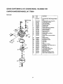
SEARS CRAFTSMAN 8.5 H.P. ENGINE MODEL 143.988503 FOR
CHIPPER-SHREDDER
MODEL 247.775880
Carburetor
Key
No.
,._
i
"15
_12
//
11
13
Part
No.
Description
640112
Carburetor (Incl. 184 of Engine Parts
List)
ThrottleShaft & LeverAssembly
Throttle Return Spring
Dust Seal Washer
Dust Seal (Throttle)
Throttle Shutter
Shutter Screw
Choke Shaft &Lever Assembly
Choke Return Spring
Dust Seal Washer
Dust Seal (Choke)
Choke Shutter
Choke PositioningSpring
Fuel Fitting
Throttle Crack Screw/Idle Speed
Screw
Tension Spring
Idle Mixture Screw
Idle Restrictor Screw
Float Bowl
Float Shaft
Float
Float Bowl "O"-Ring
Inlet Needle, Seat & Clip (Incl. 31)
Spring Clip
Main Nozzle Tube
O Ring, Main Nozzle Tube
High Speed Bowl Nut
Bowl Nut Washer
Welch Plug, Idle Mixture Well
Welch Plug, Atmospheric Vent
21
4
631970
631776A
631184
6
5
64O109
631183
710
11
12
13
14
15
16
17
632740
650506
632043
631184
631183
631753
630735
632164
651025
18
20
20A
25
27
28
29
30
31
36
37
40
44
47
48
630766
640027
64O053
631867
631024
632019
631028
631021
631022
640113
632547
640114
27110
630748
631027
24
SEARS CRAFTSMAN 8.5 H.P. ENGINE MODEL 143.988503 FOR
CHIPPER-SHREDDER
MODEL 247.775880
Recoil Starter 590746
13
12
"8
6_'_6
¢p-.4
25
Key
No.
Part
No.
Description
1
2
3
4
5
6
7
8
11
12
13
590746
590599A
590600
590679
590601
590678
590680
590412
590681
590747
590535
590701
Recoil Starter
Spring Pin (Incl. 4)
Washer
Retainer
Washer
Brake Spring
Starter Dog
Dog Spring
Pulley & Rewind Spring Ass'y
Starter Housing Ass'y
Starter Rope (98" x 9/64" Dia,)
Starter Handle
Forthe repairor replacementpartsyouneed
delivereddirectlyto yourhome
Call7 am - 7 pm, 7 daysa week
1-800-366-PART
(1-800-366-7278)
Forin-homemajorbrandrepairservice
Call24 hours a day,7 daysa week
1-8OO-4-REPAIR
(1-800-473-7247)
Forthe locationof a
SearsPartsandRepairCenterinyourarea
Call24 hours a day,7 daysa week
1-800-488-1222
For information on purchasinga Sears
Maintenance Agreement or to inquire
about an existing Agreement
call 9 am - 5 pm, Monday-Saturday
1-800-827-6655
SEARS
America's Repair Specialists
NN
mm
mmm
mmm
mmm
mmmm