1
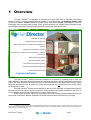
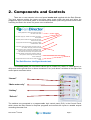
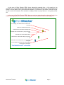
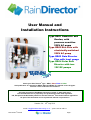
User Manual and
Installation Instructions
Type RD01 Domestic and
Garden, with
pressure sensitive
230V AC pump
Type RD02 Eco Plus with
electrically-switched
230V AC pump
Type RD03 Rain Director
Plus with level gauge
Type RD04 Solar Rain
Director with two
12V DC pumps
Check your Rain Director® type…RD01, RD02, RD03 or RD04.
Until publication of a manual for RD02, RD03 and RD04, this manual covers all types.
Note the colour coded text for variations
All rights reserved by RainWater Harvesting Limited, © 2009, 2010, 2011.
The term RainDirector is proprietary and protected by trade mark legislation.
UK, European and Worldwide patents for the Rain Director® and certain features applied for.
No part of this document can be reproduced without our permission
Version 2.4 - 18th July 2011
email: [email protected] - phone 01733 405111
®
Rain Director Manual
Page 1
1 . Overview
The Rain Director® is designed to optimise the water flow from a rainwater harvesting
system to toilets, washing machine and the garden in a typical house. Its intelligent header tank
(in the roof space), control panel (at ground level) and electric pump (submerged in the rain
harvesting tank) provide water supply under gravity wherever it’s needed while reducing power
consumption, reducing pump wear and ensuring crystal clear water at all times.
Intelligent header tank
Rainwater flows to storage tank
Water supply pipes from header tank to appliances
(yellow)
Appliances to be fed with rainwater
Rain Director controller with micro-processors, valves &
control pane
Mains water supply (blue)
Rain water supply (green)
Flush back to storage tank (yellow)
Underground rainwater storage tank
Submersible electric pump
Typical installation
1
The Rain Director® enables sufficient rainwater to be stored in a header tank to meet the
daily needs of a household’s toilet cisterns and washing machines, without continually running the
pump. The Rain Director® allows all the water in the header tank to be used before refilling, which
therefore reduces the cost of electricity1, pump wear and tear by not pumping water every time a
small amount is used.
The Rain Director® allows the household to use as much rainwater as needed and reduces
the amount of mains water used to a minimum. It also makes mains water available in the event of
a long drought, an empty rain water tank or a mains electricity cut.
While normal function requires no user input, the control panel provides additional functions
at the push of a button. Backup systems ensure fail safe operation and continuity of supply.
1
Note that an electric pump uses a disproportionately high amount of electric power (a “surge”) every time it starts up. The
Rain Director’s pump starts up many factors less often than those in other systems which have to start every time a toilet is flushed or
when pressure in the pipe subsides.
®
Rain Director Manual
Page 2
The Rain Director® has proved itself to be one of the most innovative and
successful products in the rainwater harvesting market. Its status as a
reliable rainwater management system was confirmed by the Water Regulations Advisory Scheme
(WRAS) who gave their approval in December 2009 after 6 months of testing under the approval
number 0912064. The Rain Director® is the only complete rainwater management system - rather
than just constituent parts - to have this approval. All Rain Director® models use the approved
RD01 control panel and header tank and are covered by the approval.
There are four variations to the Rain Director® range. Text in black applies to all four types, while
variations to instructions are colour coded brown, blue and green as shown here:
Type RD01 Domestic and Garden, with pressure-sensitive 230V AC pump
The most frequently-used Rain Director uses a pressure-sensitive pump in the underground
rainwater storage tank, permanently under mains electric power. The control panel has 3
pipes running through it, mains, rain and drain (refresh). Water under pressure is available
for the garden and car washing.
Type RD02 Eco with electrically-switched 230V AC pump
The submersible pump is switched on and off by the Rain Director® control panel when
required to fill the header tank. Less electricity is used. Water under pressure is not
available for the garden and car washing but gravity feed from the header is available for
drip feed irrigation and filling a watering can.
Type RD03 Rain Director® Plus
Certain installations in bigger buildings require a bigger header tank or tanks, rainwater
level gauge and the possibility of custom Building Management System connections. The
principles, detail and installation of the control panel and header tank are the same.
Type RD04 Solar Rain Director® with two 12V pumps
In response to demand for a gravity feed system using no mains electricity at all, the RD04
uses a solar PV panel, 12 volt pumps and the Charge Director to move rainwater to the
header tank. The principles, detail and installation of the control panel and header tank are
the same. Installation of the solar components is given on page 25 below, text in green.
RainWater Harvesting Limited provides tanks and components conceived and manufactured to
conform not only to the applicable British norms (The Environment Agency’s Code for Sustainable
Homes, BREAAM, WRAS, the UK Building Regulations and the Code of Practice for rainwater
harvesting systems BS 8515-2009) but also to international quality standards ISOO9001 Design &
Build, EN976, EN858, TüV or CE. Most of our products are listed on the Water Technology List
(WTL), which provides information on water-saving products that qualify for up-front tax relief for
commercial companies.
®
Rain Director Manual
Page 3
2 . Components and Controls
There are no user controls in the roof-space header tank supplied with the Rain Director.
Two level sensors register the upper and lower water levels within the tank and inform the
programme logic in the control panel. A conventional float switch (ball cock) prevents mains water
overfilling the tank in the event of a power cut or malfunction.
Mains water supply. To provide the air gap required by U.K.
building regulations, it flows into the tank from above
the surface of the water
Rain water supply pipe. Routed to the bottom of the tank to
reduce splash
Float valve prevents overflow of the mains water flow even
when there is no power
Air gap in the back wall of the tank as required by WRAS
and BS EN13077: 2003
Level sensors at the top and bottom of the tank control, via
the controller, the supply of water to the tank
Overflow tower is a large, open-topped, cylinder whose top
is below the top of the tank. If all other systems were
to fail, water flows over the top of the cylinder and out
The large diameter overflow tower provides the head and
the impulsion to ensure high volume flow through
40mm overflow pipe
Feed pipe takes water from the tank to be used around the
house
The RainDirector® intelligent header tank
3
The control panel with its solenoid valves can be located on a wall in a visible place in a
utility room on the ground floor or where convenient. Four “push button” switches on the right of the
control panel are shown below.
“Normal”
“Mains water only”
“Holiday”
“Refresh”
The switches are connected to a programmable logic control panel (PLC) in the Control Panel,
which stores the Rain Director’s computer programs and converts the inputs to useable outputs
controlling the water flow.
®
Rain Director Manual
Page 4
In the case of Rain Director RD01, three solenoids, powered from a 12v supply by the
controller, turn on and off the three water valves in the housing to the left of the control panel (see
below). A fourth water valve, the mains water bypass, is to the left of the others, and can only be
turned on and off manually. This maintains a supply if there is pump failure or a long-term power
cut.
In the case of the Rain Director RD02, there are only two solenoids as the rainwater feed to the
header tank bypasses the controller. See variations to the installation instructions at page 21.
12 volt supply from wall-socket-mounted mains
converter
Leads from header tank sensors
FLOW
Solenoid valve: flush back to storage tank
Solenoid valve: rainwater from pump in storage
tank
Solenoid valve: mains water backup
FLOW
Controller cover with aperture to show buttons
and lights
FLOW
Manual valve: mains water during long power
cut
Control panel with buttons and indicator lights
covering micro-processors
The RainDirector® controller
2
®
Rain Director Manual
Page 5
3 . Operation & Indicator Lights
2 level sensors in the header tank provide data to the computerised controller built in to the control
panel which then commands the 3 electrically-operated water valves alongside:
• 1) The rainwater solenoid valve controls the inflow of pumped water from a submersible pump
in the underground rainwater storage tank. When the valve opens, the pump registers a drop in
pressure and supplies water to the header tank until a “tank full” signal closes the valve.
• 2) The mains water solenoid valve is connected to the mains water supply. This is used
primarily as a back up water supply if the rainwater should run out.
• 3) The refresh (or “drain”) valve can be opened by the system to flush water out at any time.
In the event of a power supply failure a mains bypass can be opened manually and the tank will fill
with mains water until the conventional ball cock closes (page 8 below).
The LED lights on the right of the control panel indicate the status of the system:
Rain filling
Mains water
backup
Mains water only
A demand has been made on water supply from the header
tank so rain water is flowing normally into the header tank.
Mains water is flowing into the header tank because the rain
water tank is empty.
“Mains water only” button has been pressed, typically to save
rain water. Press “Normal” to revert to normal operation.
Holiday mode
The “Holiday” button has been pressed. The header tank has
emptied its rain water and filled up with mains water. This is to
avoid the rainwater getting yellow in the header tank. You may
flush toilets with mains water before leaving the house.
Refresh mode
Existing water in the header has been discarded and new rain
water is flowing into the header – either because user has
pressed “Refresh” or because “Auto Tank Refresh” mode has
been triggered by timer and conditions.
Mains water not
working (red)
Rain Director has also detected that the mains water is not
flowing; this could be due to the home’s mains stopcock being
turned off, major leak or some other mains water failure.
Investigate cause immediately.
Power On
Rain Director has been turned on and is under electric power.
Stays on during normal use. Flashes during “Set Up” mode.
®
®
®
Rain Director Manual
Page 6
3.1
Normal Running
During normal use the Rain Director® control system monitors and maintains the availability
of rainwater in the tank.
The Power On indicator light is on.
The Rain filling light flashes when rain water is being pumped into the header
tank.
Should the rainwater run out or become otherwise unavailable, the system
automatically switches to mains water and the Mains filling light begins
flashing.
In exceptional circumstances, the Rain Directors’ mode is changed automatically using the control
panel buttons, as follows.
3.2
Commissioning mode
Flashing
The commissioning (or “set-up” mode) is used once after installing. See
“Installation” on page 15.
3.3
Auto Tank Refresh
If the water in the header tank is not used in a 3-day period, the refresh program
automatically flushes out the system, emptying the header tank back into the
underground tank. The header then refills with fresh rainwater. This feature is disabled when the
holiday mode is running. If the house is left empty, and the holiday button is not pressed, the Rain
Director® automatically refreshes the system every 3 days. The purpose of auto tank refresh is to
prevent rainwater in the header tank (which in a roof space in summer could be at 20°C or higher)
from getting yellow; cool clear water from the underground tank (at about 5°C or less) is pumped
into the header.
Not only is this feature common sense but it also conforms to the
recommendations of the water industry. The WRAS (Water Regulations
Advisory Scheme) Information and Guidance Note No 9-02-04 on Reclaimed
Water Systems reads, under "Causes for Contamination"
“4.10: Particular attention must be paid to water replacement / turnover in all parts of the
system; periods where water is likely to be static for longer than a week are to be avoided".
3.4
Refresh Mode
The refresh mode allows the rainwater in the header tank to be changed by
pressing the refresh button on the panel. When the valve is opened the water will flush
out and is directed back into the rainwater-harvesting tank. The header is refilled with fresh
rainwater. The occupant should select refresh mode if little water has been used and the ambient
temperature is high; refreshing avoids discolouration of the rainwater by replacing the old rainwater
in the header tank. This is the same as Auto Tank Refresh but triggered manually.
3.5
Holiday Mode
The holiday mode empties the header tank and then refills with mains water.
Remember to press the holiday button a few hours in advance of leaving. Providing the
header tank has had time to fill with mains water and providing you flush the toilets twice after
pressing the holiday button, the toilet cisterns and bowls are filled with chlorinated water that stays
fresh for however long the duration of the holiday. On return from holiday all toilets and washing
machines will be available as normal and the Rain Director® system will then automatically revert
to normal mode.
®
Rain Director Manual
Page 7
3.6
Mains Water Only Mode
Once the mains water only button is pressed, the system selects mains water to
fill the header tank. The existing water in the header tank is used as usual but is
replenished with mains water. This method of operation continues until the normal
button is selected. This mains water only feature is provided to enable the rain water to be
conserved for garden use during a drought. The same pump submerged in the rain storage tank
can still be used at that time provided that its output is equipped with a T joint feeding a tap or
other garden outlet. Alternatively a second pump for garden use only can be out in the rain storage
tank.
3.7
In The Event Of A Power Cut
3.8
Time Limit Flow Mode – upper sensor failure
In the event of a power failure, firstly, water in the header tank flows by Off
gravity as required until it runs out. Secondly, thereafter, the mains water supply valve can
be manually opened and the tank will fill with mains water until the conventional ball cock closes;
see instructions in Manual mains water bypass in 3.9 below. This valve will require closing after
the power is restored.
In the unlikely event of a failure of the UPPER level sensor in the header tank,
when the Rain Director® tries to fill the header tank it establishes that the upper sensor
has not given a “full” signal, and “times out”. The Mains water not working light illuminates. Rain
Director® then switches to its back up program which fills the tank according to the flow time stored
in memory. Please also read the note on Set-Up mode in 3.2 above. The warning light indicates
that the sensor most likely needs changing (unless both rain and mains water had run out).
3.9
Manual Mains Water Bypass – lower sensor failure
In the unlikely event of a failure of the
LOWER level sensor in the header tank, Rain
Director® will not know that the tank is empty.
Water will be not be available at toilets,
washing machine and anything else fed with
rainwater. No indicator light shows.
To reinstate water supply, remove the
cover surrounding the control panel and water
valves. Select the manual (non electric) valve
to the far left (circled in green) and turn it 90
degrees to open the mains flow. Electric
power to the other valves is 12 volt only so
there is no risk of electric shock. Mains water
flows into the header tank until the ball cock
valve turns the flow off. This safety feature
works even if there is no electric power to the
system.
Call your installer or supplier to confirm
the fault and replace the part. Close the
manual valve (clockwise) to reinstate normal
functioning.
®
Rain Director Manual
Page 8
3.10 Overflow tower – multiple failures
The overflow tower in the header tank is a large, open-topped, watertight cylinder whose
top is below the top of the tank. If all other systems were to fail, and rain or mains water is flowing
unchecked into the header tank, the excess water flows over the top of the cylinder and out of the
40mm overflow pipe. The large diameter overflow tower provides the head and the impulsion to
ensure high volume flow through the overflow pipe, thus reducing to a minimum the risk of any
overflow over the top edges of the tank itself into the roof space.
3.11 Level Gauge (RD03 model only)
On the control panel, hold the top button (Normal) and the bottom button (Refresh) down
together. The 7 lights to the left will illuminate according to the level of the water in the
underground storage tank. The bottom light alone indicates “empty” while the other 6 lights indicate
how full the tank is. 7 lights indicates “full”.
3.12 Garden Use and optional smaller pump types
The Rain Director® is optimised for supply of rainwater to toilets and washing machine in the
house, but the stored rainwater can of course also be used for watering the garden, washing the
car and other outdoor uses.
For this reason the RD01 Rain Director® is supplied with a high-powered pressure-sensitive
pump which can also supply rainwater to a hose as required. The outlet to the garden can be
plumbed at any point in the pipe between the pump and the control panel, so it will get the full
power of the pump. If it’s plumbed after the control panel then that outlet will only get gravity feed.
If your system is not going to supply an outdoor tap, then use the alternative super-electricityefficient Rain Director® RD02.
®
Rain Director Manual
Page 9
4 . The header tank
The rain water supply pipe (A) is
B
routed to the bottom of the tank, in order to
A
reduce turbulence or splash.
Cutaway
view of
C
smart header tank
The mains supply (B) is at a
lower pressure and, to provide the air gap
required by U.K. building regulations, it
flows into the tank from above the surface
of the water. Mains flow is solenoid
controlled. The ball cock valve (C)
prevents overflow of the mains water flow
even when there is no power. The supply
G
of water to the tank is governed by two
level sensors at the top and bottom of the
tank (D).
The overflow tower (E) is a
large, open-topped, watertight cylinder
whose top is below the top of the tank.
If all other systems were to fail, water
flows over the top of the cylinder and
out of the 40mm overflow pipe (F). The
large diameter overflow tower provides
the head and the impulsion to ensure
high volume flow through the overflow
pipe, thus reducing to a minimum the
risk of any overflow over the top edges
of the tank itself into the roof space.
Furthermore, there is an air gap in the
back wall of the tank as required by
WRAS and BS EN13077: 2003.
The feed pipe (G) takes water
from the tank to be used around the
house. It is suitable for compression-fit
22mm copper or plastic variant piping.
D
E
D
F
B
C
D
E
A
Side view of components
of the smart header tank
D
F
G
The header tank must be
fitted at least 1.2 metres above the
highest appliance so that gravity is enough to feed those appliances. Do not use pipe
narrower than 22mm because of the risk of airlocks.
The following 5 diagrams show the smart header tank in cutaway view in different phases
of function.
®
Rain Director Manual
Page 10
4.1
Tank is empty
Lower sensor is down. Rain Director® knows tank is
empty. Controller orders tank to fill with rainwater if available.
4.2
Rain filling
Controller has sensed there is rainwater available and
has ordered tank to fill with rainwater.
4.3
Rain full
Controller has received the signal from the upper sensor
that the tank is full and has turned off rainwater input.
4.4
Mains filling
Controller has sensed there is no more rainwater and has ordered
tank to fill with mains water.
4.5
Mains full
Float valve has been raised by water. Controller knows
tank is full and has turned off mains water input.
®
Rain Director Manual
Page 11
5 . Installation
These instructions assume that an underground rainwater harvesting tank has been installed at the
site, and do not replace the instructions provided with that product. In the case of purchasing a
system from RainWater Harvesting Ltd of Peterborough, please ensure you have the tank, pump
and filter installation instructions such as at
http://www.rainwaterharvesting.co.uk/downloads/carat_tank_instructions_optimax_mains_backup.pdf
See also the schematic diagrams in paragraphs 8 and 9 below. All rainwater harvesting equipment
should be installed to the standards of British Standard BS 8515-2009.
Before connecting any pipes to the Rain Director®, it is essential they are flushed with clean water
first to release dust and debris particles. Also check your header tank is clean and debris-free. Any
particle which enters the system can block solenoid valves open and cause damage.
5.1 Pump (refers to a submersible pump as supplied with complete systems from RainWater Harvesting Ltd.)
5.1.1
5.1.2
5.1.3
5.1.4
5.1.5
5.1.6
Connect the cartridge filter (transparent, shown to the right) and small mesh
filter to the input of the submerged pump.
Pump priming: it is essential that the pump is primed by removing the half inch
cap and pouring 5 litres of water into the pump through a funnel; otherwise the
pump can burn itself out even if submerged.
Connect the outlet connection using Rainwater marked pipe of diameter
between 25-32mm. The vertical pipe should be the right length so that a right angle elbow
in the turret is at the level of the 4 inch service pipe in which the rainwater pipe is fed to the
building. As the pump holds very high pressure, the connection must be strong, secure and
watertight
The elbow should be a quick release type so that the pump can be removed easily for
maintenance, and it should be mounted high enough that it can be reached from the level
of the manhole cover.
Lower the rainwater pump into the rainwater storage tank with a cord and secure the top of
the cord to the turret of the tank to enable the pump to be pulled out again for maintenance.
Electrical connection depends on the model number. See paragraph 5.5 below and the
wiring diagrams following page 20.
5.2 Header Tank
5.2.1
5.2.2
5.2.3
Install the header tank in the roof space with antifreeze lagging as with any tank. Select an
accessible part of the roof space as you might need
access to the header tank. The header tank must be
fitted as high as possible in the roof space and at
least 1.2 metres above the highest appliance so that
gravity is enough to feed those appliances.
Keep the cover on the tank at all times during
installation to avoid roof insulation fluff falling into
the tank which can block the refresh valve. Do not
let any debris fall into the tank.
Connect the rainwater pipe from the control panel to
the upper left input to the tank (shown in light green
in the image here) and the mains water pipe from the control panel to the back of the float
valve to its right (Torbeck valve, shown in white and blue). Note: do not connect to the
Torbeck valve with flexible pipe or any installation which puts weight on the back of the
valve which would tend to bend the vertical wall of the tank: use a right angle connector and
®
Rain Director Manual
Page 12
5.2.4
5.2.5
5.2.6
rigid pipe, supported (for example where it meets the floor on which the tank is placed) to
take its own weight.
The float switch (also called Torbeck valve) may require a pressure reducing fitting. Inside
the tank there are the manufacturer’s instructions how to do so.
Connect domestic feed pipe network to header tank at (G)(see paragraph 4 above), the low
level plain outlet (shown in yellow in the image of the tank here). Use compression-fit
22mm copper or plastic piping (not smaller otherwise you run the risk of air locks in the
gravity feed pipes) except for the mains water supply pipe which is 15mm.
Connect 40mm overflow pipe to header tank at F ( see paragraph 4 above), the outlet from
the 100mm overflow tower. The overflow pipe must flow directly to the outside of the house
with minimum restriction, to a safe but conspicuous position. Do not reduce the diameter of
this pipe and ensure it runs downhill. Correct installation of this overflow is essential to
prevent any possible internal overflow during the life
of the system.
(3)
Drain
5.3 Control panel
5.3.1
5.3.2
5.3.3
5.3.4
5.3.5
5.3.6
Mount the control panel to the wall in a dry, frost
free area such as in a utility room or where mains
water is available, at least 1.2 metres below the
bottom of the header tank. In the case of the RD04
Solar Rain Director do not mount the control panel
on a partition wall or any structure which could take
up the vibration of the diaphragm pump and
solenoid. Use rubber or flexible pipe where
permitted.
Ensure control panel is within reach of available 230
Volts AC mains socket for powering the 12 volts DC
converter. In the case of RD04 Solar Rain Director,
consult the schematic wiring diagram 1 in paragraph
9 below.
The junction box on the header tank must be wired
(1)
(2)
(for example, with 0.75mm signal wires) to the
Main
Rain
similar junction box on the control panel, respecting
the colour coding, for relaying the sensor positions to the control panel. For information,
<<green/yellow is common, <blue is the bottom sensor and <brown is the top sensor.
See wiring diagram in paragraph 9 below. Header tank to control panel wiring is the same
for all models.
Connect mains water supply to the bottom of the mains valve in the control panel (1).
WRAS approval for the Rain Director® requires that;
• only copper tube must be used for connection to the
mains water supply.
• a single (non return) check valve be fitted as close as
possible to the mains water T-off.
Connect the top of the mains water valve (1) to the header
tank at (B).
Connect the supplementary rainwater filter (grey plastic,
shown to the right) to the bottom end of the rainwater
solenoid (middle valve, marked 2 in the image on page 13)
on the controller. Connect the top of this valve to the header
tank at A (light green in the image below). In the case of
RD02 connect the rainwater pipe directly from the
submerged pump to the header tank. It is vital that these
are strong, watertight seals as the pump runs at 4 to 5 bar.
A leaking connection will cause the pressure sensitive
pump to ‘hunt’ and may cause damage.
®
Rain Director Manual
Page 13
5.3.7
Connect the top of the right hand “refresh” (or drain) valve (3) to a suitable low-lying part of
the internal gravity-fed rainwater supply piping, ensuring that the whole contents of the
smart header tank can flow out of this valve by gravity when opened. Ensure that there is a
device to shut off water flow in this refresh pipe so that the user can access and clean the
filter in the refresh valve in the future. Connect the bottom of the “refresh” valve to the
underground rainwater storage tank, not to waste.
5.4 Piping (Schematic diagram can be found in paragraph 8 below)
5.4.1
5.4.2
5.4.3
5.4.4
5.4.5
5.4.6
Connect domestic feed pipe network to header tank at (G), the low level plain outlet. Use
compression-fit copper or plastic piping of a minimum diameter of 22mm (small bore
piping can lead to air locks from any gravity feed tank) except for the mains water pipe
which should be 15mm.
Connect 40mm overflow pipe to header tank at (F), the outlet from the 100mm overflow
tower. The overflow pipe must flow directly to the outside of the house with minimum
restriction, to a safe but conspicuous position. Do not reduce the diameter of this pipe and
ensure it runs downhill. Correct installation of this overflow is essential to prevent any
possible internal overflow during the life of the system.
Connect mains water supply to the bottom of the left hand valve in the control panel (1
above).
The WRAS approval for the Rain Director® RD01 requires a) (IRN
R001) that only copper tube must be used for connection to the
mains water supply and b) (IRN R155) that a WRAS-approved single (nonreturn) check valve be fitted as close as possible to the mains water T-off.
Connect the top of the valve (1) to the header tank at (B).
Connect the top of the right hand “refresh” valve (3 above) to a suitable low-lying part of the
internal gravity-fed rainwater supply piping, ensuring that the whole contents of the smart
header tank can flow out of this valve by gravity when opened. Connect the bottom of the
“refresh” valve to the underground rainwater storage tank via a roof downpipe or directly.
Water in this pipe must also flow promptly by gravity alone, therefore the “refresh” outlet
pipe must not rise above the level of the control panel nor should there be unnecessary bends in the pipe.
5.5 Electrical connections (Schematic diagram can be found in paragraph 9 below)
5.5.1 The junction box on the header tank must be wired (for example, with 0.75mm signal wires)
5.5.2
5.5.3
5.5.4
5.5.5
to the similar junction box on the control panel, respecting the colour coding, for relaying
the sensor positions to the control panel. For information, <Black is common <Blue is the
bottom sensor and <Brown is the top sensor
Plug the control panel’s 12V converter into a mains electrical socket. (RD04: plug the
Charge Director®’s 12V converter into a mains electrical socket).
RD01 and RD03: Connect the pressure sensitive pump’s cable to a permanent and
independent RCD protected 230V AC mains socket.
RD02: Connect the electrically-switched pump to the corresponding terminals on the control
panel.
RD04: see Solar Rain Director® variations, paragraph 13 and 14.
®
Rain Director Manual
Page 14
5.6 Commissioning
The Rain Director® must be commissioned, once, after installation. This process automatically
calibrates the flow timers and stores in memory the time it takes for the mains water (first) to fill the
tank and for the rainwater (second) to fill the tank. At any time thereafter, if the top sensor fails, the
tank fills with rain water (if available) or mains water according to the time intervals memorised.
The reason why the time intervals have to be calibrated for each Rain Director® installation
is because different sized header tanks, different water pressures and other variables make it
impossible to establish the fill times as a factory setting. Calibration of the flow timers by set-up
mode only needs to be completed once in the system’s lifetime unless a new header tank or pump
is fitted.
Before this process can be carried out, it is essential that any air locks are removed from the
gravity feed piping network, i.e. pipes from the header tank to the appliances. Introducing some
liquid detergent (washing up liquid) into the header tank will break down surface tension and
greatly aid this process.
5.6.1 Ensure that the header tank, all pipes and components are clean and clear of debris. The
smallest particle can block a solenoid valve open.
5.6.2 Ensure the mains water is turned on.
5.6.3 Ensure your rainwater pump is turned on and can deliver water.
5.6.4 Using the mains water bypass valve on the left hand pipe in the control panel, fill the
header tank with mains water. This valve is circular white nylon/plastic about 3 cms in
diameter and twists a quarter of a turn. When full, i.e. when mains water stops flowing due
to the Torbeck (float) valve in the header tank shutting, turn the bypass valve off.
5.6.5 Connect then turn on the mains power supply to the control panel.
5.6.6 To relieve any air locks from the system, press the “refresh” button and flush any toilets
linked to the system.
5.6.7 This process may need to be repeated.
5.6.8 When all air has been expelled from the piping network, press and hold the holiday and
refresh (bottom two) buttons on the control panel until the mains light starts to flash. This is
‘Set Up’ mode. The smart header tank empties six times and fills thrice with rainwater and
thrice with mains, so the commissioning process may take several hours.
5.6.9 During this time, check for leaks at the control panel and at the header tank, after which,
the set up mode need not be attended.
5.6.10 Check later that set up mode has completed and that normal mode has been selected
automatically. This is indicated by a solid green power light.
Trouble-shooting during Commissioning and revised software 2010
The “printed circuit board”, inside the control panel of the Rain Director controller, carries the
computer elements which control the operation of the Rain Director. There are two types of PCB in
the market, and new software for both introduced in November 2011.
5.7
PCB
name
RD01
Products
covered
RD01, RD02
RD03
RD03 with depth
gauge and
RD04 (Solar)
Visual
feature
1 fuse
block
2 fuse
blocks
Current
software 6/11
PIC 16F 882*
HEX 1.11
PIC 16F 883*
HEX 2.11
Peculiarities
Both sensors must be up for software to load. Short
the common (yellow/green or black) to upper (brown)
and or lower (blue) lead from header tank.
* refers to the device driver to select when updating software with the MP Lab ICD2.
The new software provides three changes for the installer and end user…
a) Instead of starting with a complete mains water cycle, commissioning first tests with a short
cycle (bottom sensor only) that rainwater is present (submersible pump working). This shows
within minutes if rainwater is not flowing properly and could save hours of waiting.
b) An empty tank prevention function makes sure that slow or no rainwater flow, when the
tank is nearly empty, does not permit total emptying of the tank and ingress of air into the feed pipe
to appliances which can subsequently cause airlock and malfunction of the appliances. Now, when
®
Rain Director Manual
Page 15
the lower sensor falls, if after x% of the rainwater commission time the lower sensor has not lifted,
mains water is turned on for ¼ of its commission time. Then rainwater is tried again, for ¾ of its
commission time. If the lower sensor drops then it will automatically go to mains water for a
complete fill. If it stays above bottom switch and times out before lifting the upper sensor, mains
water is used for a complete fill
c) A new light sequence shows where you are in the commissioning cycle including the
number of mains light flashes indicating which of the three fill and empty cycles is under way. This
permits an engineer or end user on site to leave the Rain Director while the commissioning
process is running set; on returning one can see where the process has got to and what any errors
might have been, i.e. you no longer have to attend the commissioning process throughout. The
fault in an interrupted commissioning cycle can be established by finding the light pattern which
corresponds with one of the steps in the table below.
1) To start
the commissioning, press
holiday
and flush
buttons at
the same
time, the
bottom
two.
2
2) Power light
flashes throughout the commissioning mode.
Tank drains if
water present
(flush light is
steady on).
3
3) When bottom
sensor
falls,
flush light goes
off, rain light is
steady.
4
4) Rain fills to
lower sensor.
When
lower
sensor rises, all
lights go off
except
flush
light which is
steady on.
Press together
5) Tank drains.
When lower sensor
drops, mains flashes once and mains
water fills. Mains
light flashes once
every few seconds.
9) Tank
empties (flush
light steady,
rain light
flashes once
every few
seconds)
5
1 FLASH
( )
6) Tank
empties; flush
light is on
steady but
mains
continue to
flash once
every few
seconds
FLASHING
FLASHING
FLASHING
(( ))
(( ))
(( ))
6
1 FLASH
( )
7) REPEATS:
Fills with mains
water (6) and
empties (7)
twice more,
flashing twice
then three
times every
few seconds.
7
FLASHES
( )
FLASHING
FLASHING
FLASHING
(( ))
(( ))
(( ))
( )
1 FLASH
9
10) REPEATS:
Fills with rain
water (9) and
empties (10)
twice
more,
flashing twice
then
three
times
every
few seconds.
( )
10
FLASHES
FLASHING
FLASHING
(( ))
(( ))
11) Cycle has
now
completed; power
light is steady,
mains water
and rain water
lights
flash
alternately to
show
that
commissioning
is complete.
( )
8) At lower sensor
after third mains fill
cycle, mains light
goes on steady,
rain light flashes
once every few
seconds. Rain fills
to upper sensor.
( )
1 FLASH
8
STEADY
11
FLASHING
( )
FLASHING
The lights stop flashing either when the water drops for the first time and fills normally or the
normal (rain) button is pressed. If there is an error at any stage, the error light is on and wherever
the error took place the lights will retain their pattern.
Note that engineers at the manufacturers RainWater Harvesting Ltd. can access the software of the computer
memory in the Rain Director controller. They can update it when on site and can use certain functions in an engineering
mode. So for installation support or if there are any issues with the functioning or light indications of the Rain Director,
contact us first. Our engineers are available by email ([email protected]) and by phone (out of hours by
prior arrangement) on 01733 405111 – ask for technical support.
®
Rain Director Manual
Page 16
6 . Power Consumption
Different types of rainwater supply in a building
Rainwater can be pumped round a building a) by direct feed, b) by gravity from a classic header
tank or c) by gravity from a smart header tank like the Rain Director®.
a)
Consumption with a classic direct feed system (not using a RainDirector®) can be up to
eight to ten times more than with the Rain Director®, i.e. about 0.5 Kwh or .5 units on a
household meter, due to a pump of 1100w running every time the toilet flushes plus drops
in pipe pressure and start-up surges. Electric motors use a disproportionately high amount
of electricity on start-up.
b)
Consumption with a simple mains header tank, i.e. rainwater flow controlled by a Torbeck
(float) valve uses almost as much electricity because the tank is kept full and the pump has
to work even when a small amount of water is called for.
c)
Consumption with a smart header tank like the Rain Director® is lowest because the header
tank is allowed to empty before it gets refilled. See next paragraph.
Using RainDirector® RD01, RD02 and RD03
During tests on the 91-litre smart header tank we found the power consumption to be around 0.06
Kwh (0.06 units on a household meter) per pump cycle (filling the tank from empty). For many
families, the tankful would last about a day. Power consumption of the RD02 is even more
economical as the pump is switched and is not maintaining pressure in the pipe when at rest.
Power use of the RD03 depends on the features and sizing of the header tank, but similar gains
can be expected over a direct feed system.
Using Solar RainDirector® RD04
The mains power consumption in normal use will be zero. Although a 230V AC mains electric
power supply is provided, the solar panel provides, even in a typical British winter, 6 times the
electrical power needed, to pump the water around to toilets and washing machine via the header
tank, for a typical home. Furthermore the Charge Director® takes zero trickle feed from the mains in
standby, i.e. it only takes mains electricity when actually needed to charge up the battery when it
falls below 11.7 volts
®
Rain Director Manual
Page 17
7 . Safety Features
The system has many inbuilt safety features
7.1
Level Sensors
The level sensors are the first barriers to flood. They turn off the rain or mains water supply when
the header tank is full.
7.2
Time Limit Flow control
Should the upper sensor fail, the control panel uses time limit flow control. The timing
values used are those calibrated for this particular system during set-up.
7.3
Ball Cock Valve
This valve limits the mains water level in the header tank even if there is a power cut.
7.4
Overflow Tower
A 4” (100 mm) diameter drain is designed to absorb the combined flow of both the rain and
mains water feeds if they were left on by the unlikely event of significant equipment failure. The
large diameter overflow tower provides the head and the impulsion to ensure high volume flow
through the overflow pipe, thus reducing to a minimum the risk of any overflow over the top edges
of the tank itself into the roof space.
With this feature in place, all the water delivered to the header tank harmlessly flows out of
the house; ideally let this flow in the open air so that there is a visual notification of a an issue to be
investigated.
®
Rain Director Manual
Page 18
8 . Plumbing Schematic RD01 RD03
Colour key
Rain Water Supply
Mains Water Supply
Water Used In The House
Overflow Water
Flushed Water
The overflow pipe must
flow directly to the
outside of the house with
minimum restriction
Header Tank
Domestic
22 mm
feed
15 mm
mains
water to
header
The header tank must be
fitted one to two metres
above the highest
appliance so that gravity
is enough to feed those
appliances.
22 mm
rainwater
to header
22mm
flush pipe
to panel
and tank
Optional outdoor tap(s) must
be connected to rainwater
pipe between storage tank
and controller. Piping as wide
as possible, 32mm
Rain Director
control panel
Flush pipe output
must not rise above
level of control panel
22, 25 or 32 mm rainwater
to control panel, reduced
to 22 mm at panel
Rainwater
Tank
Pump
®
Rain Director Manual
15 mm
mains
water pipe
Water is drawn from the rainwater tank to fill the
header tank. If no more rainwater, header filled
with mains water.
The water is then used around the house in
various appliances such as toilets and washing
machines.
The flush system is drawn from a low lying part of
the rainwater feed piping.
Any water that has overflowed or is flushed runs
out of the house and back into the rainwater tank.
Page 19
9 . Wiring Schematic RD01
Header Tank
3 core
0.75
mm
signal
wires
The junction box on the header tank
must be wired (for example, with
0.75mm signal wires) to the similar
junction box on the control panel,
respecting the colour coding, for
relaying the sensor positions to the
control
panel.
For
information,
green/yellow is common, blue is the
bottom sensor and brown is the top
sensor
Control
Panel
The submerged water pump must have
an independent 230V AC power supply
through an RCD protected socket
The Rain Director® control panel is
supplied with a 12V DC supply to plug
into a normal 230V AC wall socket
nearby
Rainwater
Tank
Pump
®
Rain Director Manual
Page 20
10 .
Rain Director RD02 Variations
In the case of the Rain Director RD02, there are only two solenoids in the controller as the
rainwater feed to the header tank bypasses the controller. This is because the pump is electrically
switched by the controller and there is no need for the solenoid to turn flow to the header tank on
and off.
The Rain Director is optimised for supply of rainwater to toilets and washing machine in the
house, but the stored rainwater can of course also be used for watering the garden, washing the
car and other outdoor uses. Unlike the Rain Director RD01, the pump of this RD02 version is not
pressure sensitive and so is not available at a tap unless the controller turns the pump on.
However, garden and outdoor water is available under gravity feed from the header tank; this
would be suitable for drip feed garden watering, filling watering cans and any slow-flow application.
02
22 0 vo lt AC su pp ly from wall-socke t þ
FLOW
Si gn al wi res from header tank sen sors þ
Soleno id valve: flush b ack to sto rage tank
þ
Soleno id valve: mains w ater b ackup þ
Manua l valv e: mains water du rin g lo ng
po wer cut þ
Control ler co ver with ap erture to sho w
b utton s an d li ghts þ
Co ntro l pan el with button s an d in dicator
l ig hts cover ing micro -p roce ssors þ
FLOW
Rainw ater pipe fr om und ergro un d ta nk is
r outed di rectly to t he hea der tank
Production mode ls might vary in pl acement o f
wiring outl ets
The RainDirector® controller
Installation, commissioning, regular use and maintenance are otherwise the same as for the RD01.
®
Rain Director Manual
Page 21
11 .
Plumbing Schematic RD02
The header tank must be
fitted one to two metres
above the highest appliance
so that gravity is enough to
feed those appliances.
Colour key
Rain Water Supply
Mains Water Supply
Water Used In The House
Overflow Water
Flushed Water
Header Tank
Domestic
22 mm
feed
The overflow pipe must
flow directly to the
outside of the house with
minimum restriction
15 mm
mains
water to
header
22mm
flush pipe
to panel
and tank
Optional outdoor tap(s)
cannot be connected to the
rainwater pipe between
storage tank and controller
as the RD02 pump is not
always on. Connect to the
appliance network for
gravity feed as shown.
240 v
mains
Control
Panel
Flush pipe must not
rise above level of
control panel
Rainwater to header tank,
min 25mm (1”) pipe to
property, then 22mm
internal to header tank
15 mm
mains
water pipe
Pump
Rainwater
Tank
®
Rain Director Manual
Water is drawn from the underground
rainwater tank to fill the header tank.
If needed mains water can be used to
help fill the tank.
The water is then used around the
house in various appliances such as toilets
and washing machines.
The flush system is drawn from a low
lying part of the rainwater feed piping.
Page 22
12 .Rain Director® RD03 Variations
“Rain Director® Plus”
The Rain Director® Plus RD03, for commercial and other larger buildings, is available to special
order. It provides options for level gauge, larger-sized or modular header tanks and Building
Management System (BMS) connectivity. The Rain Director® Plus Controller looks similar to the
RD01 but is provided with the upgraded printed circuit board to permit these options.
a)
Level Gauge: a downpipe from filter to the bottom of the underground rainwater storage
tank is fitted with 5 level sensors. On the control panel, hold the top button (Normal) and the
bottom button (Refresh) down together. The 7 lights to the left will illuminate according to the level
of the water in the underground storage tank. The bottom light alone indicates “empty” while the
other 6 lights indicate how full the tank is. 7 lights indicate “full”.
b)
Larger size header tanks: a range of header tank sizes is available to order, according to
the table below. If required, and in the case of very high peak rainwater usage, a larger solenoid
valve can be provided to ensure the required fill rate.
Capacity in litres
Number of people in building
Recommended refill rate litres/min
91
1-10
5
182
10-30
9
460
30-50
23
680
50-70
34
910
70-110
46
1360
110-150
68
1829
150-300
91
3658
> 300
183
c)
Building Management System (BMS) connectivity. The Rain Director® RD03 has builtin capability for output of real-time data to a BMS system. BMS specifications aim to standardise
interconnection between electronic devices in the building, and their and remote operation. Such
devices include any appliance with electronic controls such as; heating systems ; water systems ;
cooling systems ; control valves ; cooling system ; fire detection systems ; power cables ; fire
detection system ; maintenance contract ; access control system ; flow meters; TV and audio
visual systems; blinds and shutters. The Rain Director® control panel and microprocessors take
input from the header tank level sensors and user inputs via the panel buttons. It then controls the
three solenoid water valves to and from the header tank accordingly. Although the Rain Director is
self-contained and stand-alone, various conditions can be reported to the BMS.
Output to BMS: The RainDirector® PCB Mk 2 has a 6 pin male single inline header
connector for serial communications to, typically, a PC using an adapter cable to USB type
B. From late 2011 the Rain Director® (in an improved mass-produced injection-moulded
outer case) will be have a connection bus separate from its Mk3 type PCB , with
connections available to the outer side of the case. The serial communication protocol is
RS232 using a serial-to-USB converter IC. For most operating systems two types of driver
are available: Virtual COM Port (VCP) drivers and direct (D2XX) drivers. The VCP driver
emulates a standard PC serial port such that the RainDirector may be communicated with
as a standard RS232 device. The D2XX driver allows direct access via a DLL interface.
Comms port settings are: 19200 baud, 8 data bits, 1 stop bit, no parity.
®
Rain Director Manual
Page 23
Such BMS outputs require the firmware to be written to suit the BMS which can be
undertaken by the client (to their specifications) or by the manufacturers of the Rain
Director® as a custom option. Please enquire about lead times and pricing.
Data for out putting to BMS. The conditions which can be reported are as follows
Power on
Power off (power failure)
Rainwater mode
Mains water auto mode (rainwater depleted)
Mains water only mode
Commissioning mode
Short (engineer’s) commissioning mode
Diagnostic mode
Refresh mode
Auto tank refresh
Holiday mode
Time Limit Flow Mode – upper sensor failure
RD03 Option: level of the water in the storage tank, 6 levels reported.
Fault detected (red spanner light)
Supply voltage below 11.5v
Supply voltage below 9v
Supply voltage back to > 12.4 volts
Input from BMS (remote control of Rain Director® functions). Applications can be
anticipated which require remote control of the Rain Director®. Such functionality is
available through the same 6 pin inline connector. For further development and OEM
requirements please contact us at the Peterborough office.
®
Rain Director Manual
Page 24
13 Rain Director RD04 Variations
In the case of the RD04 Solar Rain Director, the two 12 volt pumps do not provide enough
pressure for garden watering, so a tap fitted after the header tank, i.e. gravity feed, can be used for
drip feed systems and filling a watering can. The user could also consider putting a mains electric
submersible pump into the tank for when
pressure is required (sprinkling, car washing)
alongside the solar pump.
See page 21 for schematic wiring diagrams
13.1.1 Charge Director®
The Charge Director® is a charge-monitoring
device used on the solar rain director to
ensure the battery always has sufficient voltage for the system to function. It is powered by solar
energy, so in daylight, the solar panel will trickle charge the 12v battery. As the solar panel charges
the battery the orange light will appear. When the battery reaches
its maximum necessary voltage, the green light will appear and the
system is functioning normally. Should the voltage in the battery
become depleted, the Charge Director draws electricity from its
mains charge but when on standby, this charger draws no power
whatsoever. When mains charging, the red light appears. Should
the charge director not be able to draw power from both the solar
panel and the mains, the red light will flash. This could indicate a
problem with the battery.
The Rain Director control panel also monitors the voltage. Should the power become very low the
Rain Director automatically turns off the pumps and opens the mains water valve to prevent
damage to the system.
13.1.2 The
submersible
The 12 V DC pump in the
provides water pressure to
pre-mounted on a section of
pipe into the rainwater tank
the pump is a float switch
power to the pump when
prevent the pump from
After this point, the Rain
revert to using mains water
available again.
pump (1)
underground rainwater tank
the indoor pump (2). It is
4” pipe used as the down
(image right). Adjacent to
pre-calibrated to turn off
there is very low water to
damage by dry running.
Director® will automatically
until it detects rainwater is
13.1.3 The indoor pump (2) and sound-proof housing
The indoor pump housing (image left) should be placed in a
convenient place near to the Rain Director’s control panel. The
battery should also be very close to minimise electrical losses. The
indoor pump (2) is a small 12 V DC pump that pumps the water from
the water supplied to it from the submersible pump up, through the
control box, into the header tank. This pump is encased in a sound
proofed box using a top quality acoustic foam lining. The pump has
been fully wired and simply needs plugging in as shown on the
schematic wiring diagram on page 21. Because it is a diaphragm
pump and vibrates do not mount the housing or the control panel on
a partition wall or any structure which could amplify the sound of the
vibration of the pump. Use rubber or flexible pipes around the indoor pump and control panel not
copper.
®
Rain Director Manual
Page 25
13.1.4 The Solar panel
The Solar panel should be mounted on a roof space with high exposure to direct sunlight. The
panel is designed to charge even in typical British overcast weather. A blocking diode prevents
reverse charging and protects battery discharge. Optimum Output current of 580 milliamps is
stated by the manufacturer. We tend to get more like 350 milliamps on the test bench in real
conditions.
Charging power: 12 watts nominal power. We have measured it over time at an effective 8 watts
when charging a car-type lead-acid battery. This panel, in typical UK conditions, even cloudy,
generates 6 times the amount of power needed by the Rain Director® for a 4 person home (toilets
and washing machine).
13.1.5 Installation
If you are installing a Solar Rain Director RD-04, proceed as shown on this page.
Consult the schematic wiring diagram 2 in paragraph 9 below.
1. (RD04 Solar Rain Director only). The submersible 12volt pump (1) and float switch are factory
fitted to a 4 inch pipe as housing. The float switch is adjusted so that the pump cannot run dry.
Insert the normal 4inch downpipe, cut to length so that it supports the filter at the right height, in
the female flange of this pump housing. Connect the calmed inlet to the bottom of the pump
housing (see photo on page 25).
2. Connect 1 inch (25mm) MDPE or high quality flexible pipe with jubilee clip (neither supplied
with this product) to the submersible pump (1) and run it to the input of the indoor pump (2).
The input to the indoor pump enters through the hole in the housing next to the five wiring
connectors, using the 25mm to 15mm adaptor provided. Connect the output of the indoor pump
(2) to the header tank, typically with 22mm MDPE pipe (not supplied with this product).
3. Secure the junction box (12 volt pump and float switch cables converging) to the wall of the
turret of the tank. Draw the black 3 core cable from this junction box through the service pipe to
the building.
4. Install a) the Rain Director control panel, b) the Charge Director, c) the sound-proof pump
housing, and d) a 230 V AC mains socket on a wall of a suitable locale in the building (garage,
kitchen, laundry) as close as possible to each other. The 12 V DC battery (e) can be on the
floor or a shelf as close as possible to the other units. The battery is not supplied with the
product: obtain a normal 12 volt car battery or gel battery, even a used one, of about 30 to 120
amp-hours. Do not yet connect the 12 volt battery to the units.
5. Connect the black 3 core cable from the 12 volt pump and float switch to the 3 right hand
terminals on the sound-proof pump housing, <blue to blue, <black to the black 2nd from the
right and <brown to <yellow.
6. Affix the solar panel using the screws provided to a wall or roof exposed to sunlight and
pointing as close as possible to South. Connect the two ends of the cable to the Charge
Director, the <red wire to the 2nd terminal (marked with a sun and +) and the <black wire to
the 1st terminal (marked with a sun and -), respecting polarity.
7. Connect the two central terminals (18volt DC) of the Charge Director to the mains charger
supplied but do not yet switch it on. Do not connect the Charge Director directly to the mains.
8. Connect the two right hand terminals of the Charge Director to the battery, respecting polarity,
i.e. < red to + and < black to – (negative).
9. Connect the Rain Director control panel (a) to the battery, respecting polarity
®
Rain Director Manual
Page 26
14 .
Wiring Schematics RD04
Wiring schematic Solar Rain Director RD-04.
1) 12 volt DC wiring in the building
d ) 230 Volts AC wall
so ck e t f or 1 2V DC
C on ve rt er
a ) Rain Di re cto r
Co n tro l P an el
b ) C h ar g e D irec tor
Solar
Pan e l
c) Soun d -p r oo f p u m p ho u sin g
with pump 2 a nd p r ess u re sens itiv e s witch
e) 1 2V DC b at tery
1 2V DC 3 -c ore
cab l e t o tan k
Wiring schematic Solar Rain Director RD-04.
2) 12 volt DC wiring and piping in tank
Da m p- resistant
connector in turret
of tank
Float sw itch,
fac to ry fitted to
h ou sin g
12V DC 3 -core
cable to
sou n d pr oo f pu m p
ho u sin g
W a ter t o
cont ro l p an e l
4 i n c h do wnpipe fr om
filt er to c almed inlet ,
n o t p ar t of Solar Rain
Dir ec tor
4 i n ch h o using f or p u m p 1 a n d
float switch
P ump 1
Minimu m w at er l e ve l
Floor of ta n k
®
Rain Director Manual
C a l m ed inlet, not part o f
Sol ar R ain D i re ct or
Page 27
15 .
Component parts
1. Header Tank. 91 litre rectangular water tank with removable lid to act as the header tank.
a. 2 X level sensors to give an input to the programmable logic controller.
b. 1 X 100mm inner diameter water pipe with blanking plug to act as overflow tower
c. The header tank is designed for installation in the roof space. Allow space at the rear
(mains and rainwater input pipes) and at the front (rainwater output and overflow output
pipes). Picture in paragraphs 2 and 4 above.
d. Dimensions 91 litres: 665mm (L) x 490mm (W) x 510mm (H) (K20R)
e. Insulation cladding is available as a low cost option (Product ID : TJ20R60)
f. Larger or multiple header tanks, or a lower level sensor mounted higher on the tower in
the tank, are available under the options in RD03 for installations where the
simultaneous demand for water (more than about 8 toilets for example) might make the
small tank run dry momentarily.
2. Control Panel, including
a. 3 X 1/2” normally closed male mini Series Solenoid Valves (7202NC) with 12v A.C.
electrical connections to control the valves running the mains supply, rainwater supply
and refresh. Connections 22m. 2 solenoid valves for RD02.
b. 1 X manual valve attached to the mains water supply to enable manual mains water
bypass. Connections 15mm.
c. 1 X dedicated logic controller (PLC).
d. 4 X generic system control buttons.
e. 7 X generic LED indicator lights
f. Dimensions: 325mm (W) X 260mm* (H) X 95mm (D) (D = depth front to back). The
control panel is designed for wall mounting. * Space should be available above and
below the panel for the input and output pipes. The fittings protrude about 100mm
above and below the control panel housing, so the overall vertical wall space required is
about 460mm.
3. Pump. 1 X Automatic, pressure sensitive 1100 watt, 230V AC, 11.5kg 1hp pump to pump
water from the rainwater storage tank.
4. Solar Rain Director RD-04 only
• Pump 1. Self-priming and fully submersible 12 V DC pump with 1.4 bar pressure switch and
dry-run-protect level sensor, flow rate: 34 litres/min., head: 1.8 bar nominal but down to 1 bar at
12 metres above pump, power consumption: 50 watts, dimensions: 250 (L) x 42 (diameter)
mm.
• Pump 2. The indoor diaphragm pump is a 12V DC non-submersible diaphragm pump, 2.8 bar
max, 11 litres per minute max mounted with a pressure switch in the sound-proof housing.
• Solar (Photo Voltaic) Panel. Amorphous solar panel charger, blocking diode prevents reverse
charging and protects battery discharge, optimum output current 580 MilliAmps (350 milliamps
on our test bench),12 watts nominal power, external dimensions 98(L) x 34(W) x 1.5(D) cm.
• Charge Director ensures mains electric backup if battery runs low (Pulse-switched zero-trickle
PSU) and gives four indications from its 3 coloured lights...
Green: battery is OK.
Yellow: primary (the solar panel) is charging.
Red: Charging from mains. Flashing red: mains switched off or system error.
®
Rain Director Manual
Page 28
16 .
Washing machines
Some modern washing machines require a higher pressure of water than older machines.
Manufacturer’s spec often states 1 to 1.5 bar. This is because the washing machine’s controller
measures the times time taken for the water to fill the washing machine and times out if it is not
fast enough.
In the case of Miele, Electrolux, AEG, Zanussi and Tricity washing machines, the
manufacturers recommend you ensure that the header tank is at least 16.5 feet (5 metres) above
the washing machine. This problem can occur in any home with a header tank, not just with
RainDirector®. However, in the documented experiences, most machines work with 0.5 bar or less,
and it is likely that you will have no issues.
If you cannot get the header tank as high as that, fit up the piping and see if the washing
machine works satisfactorily. If not, here are some remedies.
1)
Ensure the piping from the header tank to the washing machine is as wide as possible and
has no constrictions at the joins.
2)
Have the pressure-reducing spiral at the water input of the washing machine removed (n.b.
check whether this invalidates your washing machine guarantee)
3)
Failing which, fit a pressure-sensitive booster pump at the rain output of the header tank or
before the water input of the washing machine. Such a pump is available from a plumber, a tool
catalogue retailer or Rainwater Harvesting Ltd.
Note that it is not permitted under the Water Regulations to feed both mains and rainwater to the
washing machine selectable by a two position cock (risk of backflow). To provide choice of water
source at the washing machine, fit both the mains and rainwater pipes with the correct thread to
permit the flexible pipe from the washing machine to be connected to either, manually.
17 .
Guarantee
All components and the ensemble are guaranteed by the manufacturer as follows, as per the
standard terms and conditions of RainWaterHarvesting.co.uk .
•
•
•
One (1) year from the date of shipment in the case of electrical products and or products with
moving parts (including but not limited to pumps and rain management systems), except
Two (2) years from the date of shipment in the case of the Enviro 1100w submersible rainwater
pump (Product ID: RWH-ENV100),
Two (2) years from the date of shipment in the case of products without moving parts (including
but not limited to filters, pipes and tanks).
®
Rain Director Manual
Page 29
18 .
Maintenance
The RainDirector® control panel and header tank are essentially maintenance-free, but advice for
the rest of the system is also given here for information.
The filter is maintenance-free if the soakaway or drain has been properly constructed. After the
first autumn, lift the manhole cover, lift the lid off the Optimax filter to check that leaves are not
accumulating there. If so, investigate the cause. Normally the flow of water pushes leaves and
debris off the filter to drain.
The tank is maintenance-free. As in an underground rock pool or stream, any vegetable and other
debris sinks to the bottom as fine silt and should not enter the pumped supply. Silt can enter the
pumped supply under 2 conditions: 1) The floating inlet sinks into the silt layer when the tank is
nearly empty, soon after installation. Solution: ensure the float switch of the pump is adjusted so
that the pump gets turned off as water level drops before the floating inlet touches the silt layer. 2)
The silt layer has built up so much over time that the floating inlet now sucks up silt. Solution: clear
out the silt by lowering a dirty pump to the bottom of the tank and pumping it out.
The Rain Director control panel’s only moving parts are solenoid valves which are from the British
manufacturer John Guest “SpeedFit” range and proven in quality and reliability over a long period.
These solenoids can jam or otherwise fail if grit is present in the water. Turn off the pump, detach
the pipes from the solenoid, clear the filter if fitted and blow grit out with an airline.
Table of suggested intervention, inspection and maintenance
When
Before turning on pump
After installation
During first autumn and
annually
Annually
After first year’s use
After ten year’s use
After ten year’s use
®
Rain Director Manual
Why
How
Ensure bottom of rainwater
storage tank is free of grit and silt.
Confirm that water is flowing to
waste and washing the filter
properly
Confirm that leaves are being
pushed to waste satisfactorily
Pump out with a separate “dirty”
pump before first use
Lift manhole cover and inspect
visually. If weak, consider
enlarging soakaway
Lift manhole cover and inspect
visually. If poor, consider
enlarging soakaway
Lift filter mesh out by hand and
clean from all angles with hose
If silt level high at any time,
pump out with a separate “dirty”
pump suspended on a cord.
Check for possible blocking of the
filter mesh
Check level of silt in bottom of
storage tank has not risen to the
top of the calmed inlet (about
12cms)
Silt accumulates at 0 to 20mm a
year (leaf matter, dust off the roof
and other dirt)
Pump life might be nearing its end.
Check flow rate and bearing noise.
Pump out silt with a separate
“dirty” pump suspended on a
cord.
Replace pump if necessary.
Page 30
Revisions:
V.1.16 Pipe diameters added to 5.4.2 and 11.2.
V.1.17 Refresh pipe instructions clarified in text and on plumbing schematic.
V.1.20 WRAS approval installation requirements added
V 1.21 Refresh modes wording improved, Solar Rain Director added in green
V 2.1 Flush mode renamed refresh mode to avoid confusion with toilet flushing. Solar Rain Director instructions added in green coloured
font. Commissioning process clarified. Comparative table deleted. Text in images made more readable. Float sensors now called level
sensors throughout. Maintenance chapter added.
V 2.2 Torbeck valve need self supporting mains water pipe, p12. Washing machine double connection Para 13.
V 2.3 Small changes based on experience with faulty installations. Filter added to rainwater feed pipe. Instructions for RD02 and RD03
models added and clarified. Text colour-coding set for all 4 models. New software and commissioning mode light indications added. Doc
renamed User Manual and Installation Instructions. Torbeck valve piping must be self-supporting.
V 2.4 Image of grey filter added, priming of pump
All rights reserved by RainWater Harvesting Limited, © 2009, 2010, 2011
The term RainDirector is proprietary and protected by trade mark legislation.
UK, European and Worldwide patents for the Rain Director® and certain features applied for.
No part of this document can be reproduced without our permission
R.Lester, A.Lester, Jd.Lester, M.Bicknell [email protected] - phone 01733 405111
RainWater Harvesting Limited, Unit A, Harrier Park, Southgate Way, Orton Southgate, Peterborough PE2 6YQ, United
Kingdom - Phone +44 (0)1733 405111 - Fax +44 (0)1733 230996
Email [email protected] - web site www.RainWaterHarvesting.co.uk
®
Rain Director Manual
Page 31
®
Rain Director Manual
Page 32