1
www.servicemotoguzzi.com
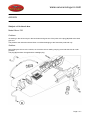
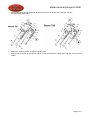
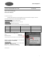
EXHAUST SILENCERS
Subject: exhaust silencers
Model: Breva 750
Problem:
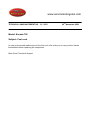
The exhaust silencers come off due to the inadequate length of the exhaust pipes.
Solution:
For the new bikes, the exhaust pipe length has been changed.
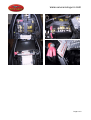
For the bikes already manufactured, the problem can be solved by cutting slots on the silencer brackets (A).
Page 1 of 1
www.servicemotoguzzi.com
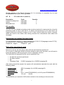
TECHNICAL ANNOUNCEMENT No. 08-2003
22nd September 2003
Model : Breva 750
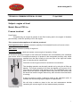
Subject: Side bags
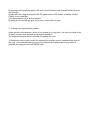
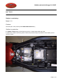
After mounting the side bag attachments, it is necessary to check that the distance
between the top of the silencer and the bottom of the bag is 15 mm at least.
15 mm MINIMUM
If this distance is shorter, it is possible to lift the bag attachments by shortening of 10 mm
the bushes placed between the attachments and the bike frame.
10 mm
Should this minimum distance of 15 mm not be complied with, the bags could be damaged
due to the heat produced by the exhaust fumes.
Page 1 of 1
www.servicemotoguzzi.com
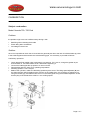
AIR BOX
Subject: oil in the air box
Model: Breva 750
Problem:
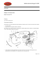
oil entering in the air box stays in the box bottom and goes out of the joints or the plug (A) fitted at the drain
pipe end.
The problem was claimed on demo bikes or on bikes belonging to the first series produced only.
Solution:
before fitting the air box to the vehicle, we check the air box sealing carrying out a leak test with air under
pressure.
The plug (A) has been changed with a watertight plug.
Page 1 of 1
www.motoguzzi.it
TECHNICAL COMMUNICATION No. 02-2003
17 April 2003
Subject: engine oil level
Model: Breva V750 i.e.
Frames involved:
all
Dear Dealer,
if experiencing an engine oil present in the filter housing and in the engine oil breather
pipe anomaly, check the quantity of oil in the engine.
This communication applies to all vehicles produced.
Fault experienced on vehicle: excessive quantity of oil extracted from the oil recover circuit.
Main cause: excessive quantity of engine oil.
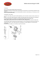
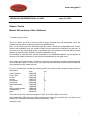
Technical solution: check and restore correct engine oil quantity (1.8 kg).
Upper mark
10 mm
An excessive quantity of engine oil can cause an increase in the oil extracted by the crankcase
gas recover circuit. In exceptional cases an oil present in the transparent recovery tube, which
extends from the filter housing to the rear joint of the right half cradle,
type of anomaly can be experienced.
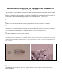
Check the correct engine oil level to avoid this inconvenience.
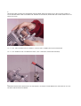
The checking operation can be easily carried out by using the oil filler cap
dipstick. The correct quantity of oil wets the dipstick up to around 10-11
mm under the maximum level reference mark. The highlighted part in the
photo shows the section of dipstick which must be wet. The check must
be carried out with the engine warmed up, after around 20 minutes that it
is running.
It may be useful to make a reference mark at the indicated quota, to
facilitate the check during regular engine oil replacements.
We will ship a sticker to place in the use and maintenance booklet
containing the correct engine oil level measurement procedure.
Yours Sincerely,
1
www.servicemotoguzzi.com
INSTRUMENT PANEL LIGHTS
Subject: INSTRUMENT PANEL LIGHTS (the first 100 bikes)
Model: Breva 750
Problem:
the instrument panel plastic parts touch a transistor that turns on or off some lights in an erratic way.
Solution:
change the instrument panel.
Page 1 of 1
www.servicemotoguzzi.com
THROTTLE POSITION DATA MISSING
Subject: Throttle position data missing
Model: Breva 750
Problem:
the engine does not work correctly and tends to stop. The parameter “Correct throttle pos” read with Axone
indicates 2.3 ° (normally, it should read between 2.7° and 3.5°).
Solution:
reset the throttle with Axone.
Adjust the cylinder synchronization and idle speed.
Page 1 of 1
www.servicemotoguzzi.com
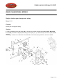
GEARCHANGE PRESELECTOR
Subject: jamming of gearchange preselector
Model: Breva 750
Problem:
the slide inside the preselector might jam when in contact with the two pins (A).
Solution:
the diameter of the pins was increased
(from 7.0 mm to 7.2 mm), and the
concentricity tolerance was decreased.
Page 1 of 1
www.servicemotoguzzi.com
GEARCHANGE
Subject: Gearchange clutch dogs
Model: Nevada 750
Problem:
the 3rd and 4th gears slip out.
We highlighted two causes:
1. The circlips (S) doesn’t keep the washer in place.
2. After inspecting the 3rd and 4th gears clutch dogs, it was noticed that the angle was not correct (should
be 6°) maybe due to wrong machining or because it was exchanged with one for the Breva 750
gearchange.
Solution:
1. it was fitted the circlip for the Breva gearchange (inner diameter undersized by 0.5 mm part no.
90271124).
2. Changing the gears that do not comply with the drawings.
NOTE : the gear for the Nevada 750 gearchange is marked with number 6
Page 1 of 1
www.servicemotoguzzi.com
TECHNICAL ANNOUNCEMENT NO. 10 - 2003
20th November 2003
Model: Nevada 750
Subject: Fuel cock
In case of presumed malfunctions of the fuel cock, We invite you to carry out the checks
listed below before replacing the component.
Moto Guzzi Technical Support
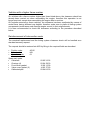
DIAGNOSTICS SHEET FOR
THE NEVADA 750 ELECTRICALLY
ACTUATED FUEL COCK
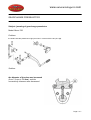
1. Generalities
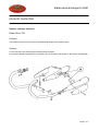
The electrically actuated fuel cock is made up of the following parts:
• body of the cock
• electric actuator (this is in turn made up of a solenoid and of mechanical actuator
provided with an O-ring at the end)
Solenoid
Actuator
O-ring
Body of the cock
2. How to test the cock
In order to carry out the test easier, connect a wired counterpart to the cock connector.
Connect a multimeter between the two wires and place the multimeter in Ω mode
(resistance measurement).
The resistance should be 33±2 Ω
By blowing into the delivery side of the cock, check that the cock does not allow the air to
flow through.
Supply the cock using an external 12V DC power source (DC feeder or battery feeder).
Polarity is not important.
You should hear a “click” by the actuator.
By blowing into the delivery side of the cock, check that it is open.
3. Solving the most common problem
Under certain circumstances (when it is not used for a long time), the cock is locked in the
"closed" position, thus preventing the engine operation.
The solenoid strength alone is not able to operate the cock.
To unlock the cock, simply loosen the solenoid by one/two turns in relation to the body of
the cock. It is recommended to remove the solenoid and replace the O-ring, which is
available as spare part with 90706020 code.
www.servicemotoguzzi.com
AIR BOX
Subject: oil in the air box
Model: Nevada 750
Problem:
too much oil in the air box
Causes and solutions:
The presence of oil in the decanter box and -following oil vapours circuit- in the air box has two main causes:
•
•
too high oil level
high pressure of the gases inside the crankcase
With reference to the engine oil level, it is important to carefully read the techn. bulletin no. 002-2003 dated
17 Apr. 2003 referred to Breva 750 vehicles.
•
Check that the two hoses (A) taking the oil vapours from the head covers to the decanter are not
squashed due to their flexibility; if so, change them with more rigid hoses.
Page 1 of 2
www.servicemotoguzzi.com
•
Change the hose (C) and the shims (B) with the ones for the Breva 750 model (for vehicles
manufactured before 2003).
•
•
Should the problem persist, change the piston rings.
Should it be necessary to change the pistons, it is recommended to change them with the ones for Breva
model.
Page 2 of 2
www.motoguzzi.it
TECHNICAL COMMUNICATION No. 02-2003
17 April 2003
Subject: engine oil level
Model: Breva V750 i.e.
Frames involved:
all
Dear Dealer,
if experiencing an engine oil present in the filter housing and in the engine oil breather
pipe anomaly, check the quantity of oil in the engine.
This communication applies to all vehicles produced.
Fault experienced on vehicle: excessive quantity of oil extracted from the oil recover circuit.
Main cause: excessive quantity of engine oil.
Technical solution: check and restore correct engine oil quantity (1.8 kg).
Upper mark
10 mm
An excessive quantity of engine oil can cause an increase in the oil extracted by the crankcase
gas recover circuit. In exceptional cases an oil present in the transparent recovery tube, which
extends from the filter housing to the rear joint of the right half cradle,
type of anomaly can be experienced.
Check the correct engine oil level to avoid this inconvenience.
The checking operation can be easily carried out by using the oil filler cap
dipstick. The correct quantity of oil wets the dipstick up to around 10-11
mm under the maximum level reference mark. The highlighted part in the
photo shows the section of dipstick which must be wet. The check must
be carried out with the engine warmed up, after around 20 minutes that it
is running.
It may be useful to make a reference mark at the indicated quota, to
facilitate the check during regular engine oil replacements.
We will ship a sticker to place in the use and maintenance booklet
containing the correct engine oil level measurement procedure.
Yours Sincerely,
1
www.servicemotoguzzi.com
CARBURETION
Subject: carburetion
Model: Nevada 750 / 750 Club
Problem:
the problem might come out in different ways during a ride.
•
•
•
Backfiring when releasing the throttle
Erratic idling after acceleration
Air leakage in the air box
Solution:
Since it is impossible to check the CO level with the gas analyser due to the lack of individual take-up points
in the exhaust pipes and because there is the balancing pipe, it is necessary to proceed as follows.
Preliminary operations
•
•
•
•
•
Check that the float needle valve (carburettor) is screwed in. If it is not so, change the gasket as per
techn.bulletin no. 001-2003 dated 16 Jan. 2003 before tightening it.
Connect the intake pipe take-up points to a vacuum meter.
Start the bike and let it warm up to operating temperature.
Set idling speed to 1150 ± 50 rpm.
Balance the cylinders, make sure that idling speed stays the same. The idling speed adjusters (A) are
the same that are used for balancing the vacuum on the intake pipes. It is necessary to slightly rev up,
using the throttle grip, and balance the vacuum in the intake pipes using the threaded adjusters. Check
that the play of the throttle drive cable is 1 mm at idling speed.
Page 1 of 1
www.servicemotoguzzi.com
Carburetion
Use the mixture adjusters (B) to adjust the carburetion.
The correct compromise is reached when the engine goes smoothly back to the set idling speed after having
revved up.
Should it not be possible to reach a smooth idling speed even after a careful setting, it is necessary to check
valve and cylinder head sealing.
Checking the valve sealing
Check the valve sealing using the SUN-TEST (BOSCH), put the combustion chamber under a pressure of 5
bars.
If you do not have the suitable equipment available, build fake spark plugs with the fittings for compressed
air; these spark plugs are to be fitted on the cylinder heads instead of the real spark plugs.
Bring the piston of the cylinder head to be checked to the TDC (valves closed).
Then supply compressed air at 5 bars to the head and check air leakage from the exhaust or intake valve.
The SUN-TEST system is fitted with two pressure gauges, one for checking inlet pressure and another one
reading the pressure on the cylinder head; there will always be a certain difference, but it should never
exceed 20%.
If the test result is negative, it is necessary to grind the valve seat.
Page 2 of 2
www.servicemotoguzzi.com
REV COUNTER
Subject: rev counter
Model: Nevada 750
Problem:
erratic rev counter
This problem is under analysis, up to now we have found the following possiblecauses:
•
•
rev counter not working with high air temperature
water in the main wiring harness, at the curve next to the rear brake master cylinder.
Page 1 of 1
www.servicemotoguzzi.com
OIL PRESSURE RELIEF VALVE
Subject: broken oil pressure relief valve
Model: Breva 750
Problem:
oil pressure relief valve breaks in the area where the oil outlet holes are.
Solution:
change the oil pressure relief valve with the component used for the Breva 750 engine.
Page 1 of 1
www.servicemotoguzzi.com
BATTERY
Subject: new battery
Model: California CAT
Problem:
short life-span of the presently fitted battery due to fluid leakage (30 Ah EXIDE standard type (29.52)).
Solution in production:
the 20 Ah sealed Exide ETX20 battery and then the Yuasa YTX20 battery (is to be filled with fluid before
delivery) will be fitted by January 2004.
Page 1 of 1
www.motoguzzi.it
TECHNICAL INFORMATION No. 03-2003
June 12th 2003
Object: Clutch
Model: All versions of the California
To whom it may concern,
This is to inform you that a clutch set with a single sintered disc was assembled on all the
California motorcycles models produced from September on.
Also, on all motorcycles with sintered single disc clutch, which are recognizable from a lower
load on the handlebar lever, be certain to check more frequently the clearance on the lever, in
as much as in the initial using period, it is possible that the clearance void itself with the result
that the clutch sticks and, therefore, become irreparably ruined.
Be reminded as well that work can be performed on the handlebar adjuster, on the adjuster at
the end of the cable as well as on the clutch lever assembled on the gear cover.
Note, finally, that a percentage of clutches may show some abnormal wearing phenomena due
to the material’s defect. In such a case, you may request a warranty covered work to substitute
the complete set with a dual disc set.
For your convenience, we add the ordering codes list as well as the operation code to insert in
the system:
code
q.ty
motor flywheel
03067030
1
crown gear
17067900
1
screws
98084420
8
screws
12067701
6
flat washer
14615901
18
clutch disc
03084400
2
intermediate disc
12082300
1
cup
12082800
1
spring retaining plate
12082901
1
clutch spring
13084100
8
gear
30081810
1
The code to use for the warranty request in A2D is AF 209 MD01 (6,2 hours)
After inserting the MD code, the system will ask you for the note, at which point you will need to
provide the “Technical Information Reference03-2003 ” note.
Sincerely yours
1
www.motoguzzi.it
TECHNICAL ANNOUNCEMENT No. 11-2003
22nd December 2003
Object: Clutch
Model: All versions of the California
Dear Dealers,
in the light of the technical announcement 03-2003, We inform you that a double-disc clutch kit
has been created, which groups all the components listed in the previous announcement.
The kit is available as spare part with the code : 973253600008
Best regards
1
www.motoguzzi.it
TECHNICAL ANNOUNCEMENTS NO. 04-2004
July 15th 2003
Object: control unit identification
Model: California MY03 kat
To whom it may concern,
should the engine delivery show some irregularities, please check the label of the engine’s control unit.
This announcement concerns all the California MY03 kat models.
Defect found on vehicle: engine’s irregular delivery
Possible cause: wrong gauging of the electronic control unit
Technical solution: control unit’s replacement
A control unit compliant with the following criteria will include the correct gauging:
Correct control unit
Correct control unit
Control unit to replace
Serial No.
IAW5RC.C8
IAW5RC.C8
IAW5RC.C8
MM logo
61601.048.01
61601.048.00
61601.048.00
absent
present
absent
yellow mark
The serial number and the Magneti Marelli logo are printed on
the control unit’s label in the highlighted spots:
serial:
Magneti Marelli logo:
IAW5RC.C8
61601.048.01
the yellow mark can be on the label or on the control unit’s body.
Should the control unit assembled on the vehicle be
incorrect, replacing it is indispensable.
Operating request:
Insert the following codes when filling out the warranted request:
Position code:
AM04 (control unit)
Defect code:
MD (defect non provided for)
Operation code: 01 (disassembly and reassembly)
Sincerely yours
1
www.servicemotoguzzi.com
TECHNICAL ANNOUNCEMENT No. 12 - 2003
3rd December 2003
Model: Frame hydraulic tappets - California engine < see table
Subject: Noisiness of the timing system
Dear Dealers,
in case of noisiness of the timing system for the California p.i. models with a frame number
preceding the numbers listed below, the camshaft may be worn.
Titanium
Titanium Usa
EV - EV Touring
EV Touring USA
Stone
Stone USA
ZGUKDC1203M133654
ZGUKDD0074M133659
ZGUKDC1203M112261
ZGUKDD0024M112346
ZGUKDC4203M111687
ZGUKDD0164M111418
Therefore, if the above mentioned components are seriously damaged (some material is
clearly missing) and if metal residuals are found inside the oil sump, the camshaft and the
4 closings must be replaced, and the engine must be overhauled completely, if needed.
In the following pages the procedure for assembling the new camshaft is described, with
particular reference to the measuring of the timing system clearance.
We also point out that measuring the clearance and readjusting it by means of a calibrated
pad is absolutely necessary when assembling the engine, in order to ensure the system
reliability, since, in case of an excessive clearance which cannot be recovered through the
hydraulic tappets, the camshaft lobes will be subjected to impacts during engine operation,
resulting in a quick wear.
Vehicles with a higher frame number
On vehicles with a frame number higher than those listed above, the clearance check has
already been carried out when assembling the engine; therefore this operation is not
longer required, except when assembling the engine after a revision.
On engines mounted on these vehicles, the clearance has been readjusted by means of
rocker arms having different cap heights; therefore make sure to place all timing system
components (rocker arms-rods-closings-engine mount) in their original seats.
It is also recommended to check the clearance according to the procedure described
below.
Reimbursement of intervention costs
The camshaft replacement and the timing system clearance check will be handled as a
standard warranty request.
The request should be entered into A2D by filling in the required fields as described:
•
•
•
Position code:
Defect code:
Operation code:
Spare part codes
• Camshaft
• Closings (4)
• Front cover gasket
• Valve cover gasket (2)
• Calibrated pad
AC05
HB
01
03 05 33 32
03 04 58 30
12 00 12 00
14 02 37 60
03 04 83 30
PROCEDURE FOR MEASURING THE TIMING SYSTEM CLEARANCE OF
THE 1100 p.i. ENGINE
The procedure described below concerns the timing system clearance measurement after the engine
has been assembled.
In case of camshaft replacement, the step order will be different from the one reported below; as a
consequence, the engine assembling sequence to be followed will be: 3-4-5-1-5-6-7
1
BRING THE LEFT PISTON TO TDC, DURING THE IGNITION STROKE.
2
REMOVE THE ROCKER ARMS, THE TIMING SYSTEM RODS AND THE HYDRAULIC TAPPETS.
3
DRAIN THE 2 HYDRAULIC TAPPETS BY APPLYING AN AXIAL LOAD OF ABOUT 100 KG, OR UNTIL THE
OIL SPILLS OUT AND THE TAPPET CLOSES (USE A PRESS OR A BENCH VICE WITH JAW CAPS MADE OF
SOFT MATERIAL).
THE TAPPET IS DRAINED WHEN IT CAN BE MOVED BY USING THE FINGERS ONLY.
4
FIT THE CALIBRATED PAD INTO THE CLOSINGS
NOTE :
IF A SIMPLE CHECK IS REQUIRED, THE CALIBRATED PAD CAN BE FITTED INTO THE CLOSING DIRECTLY FROM
THE HEAD, WITHOUT DISASSEMBLING THE CAMSHAFT AND THE CLOSINGS.
IN THIS CASE, ATTACH THE CALIBRATED PAD TO THE TAPPET (BOTTOM PART), GREASING IT WITH ENGINE OIL
IN ORDER TO STICK IT TO THE TAPPET AND TO EASILY INSERT THE TAPPET WITH THE CALIBRATED PAD INTO
THE CLOSING.
BY USING A LIGHT SOURCE, CHECK THAT THE CALIBRATED PAD IS FITTED INTO THE CLOSING.
5
FIT THE CLOSINGS, THE PADS AND THE DRAINED HYDRAULIC TAPPET INTO THE BLOCK;
REASSEMBLE THE CAMSHAFT AND THE TIMING SYSTEM (GEARS-CHAIN-RODS-ENGINE MOUNTROCKER ARMS).
6
MEASURE THE CLEARANCE BETWEEN THE ROCKER ARM AND THE VALVE, BY HAVING CARE TO
PUSH THE ROCKER ARM TOWARDS THE TIMING SYSTEM ROD (PERFORM THE SAME OPERATION ON
BOTH VALVES)
IF > 1.1 mm THE CLEARANCE IS CORRECT, LEAVE THE CALIBRATED PAD IN POSITION
IF < 1.1 mm REMOVE THE CALIBRATED PAD (USE A MAGNET; SEE PHOTOGRAPH)
7
PERFORM THE SAME OPERATION ON THE RIGHT CYLINDER AFTER BRINGING THE PISTON TO TDC
DURING THE IGNITION STROKE.
www.servicemotoguzzi.com
TECHNICAL ANNOUNCEMENT No. 07-2003
July 22nd 2003
Object: AXONE 5.0.0 version
The 5.0.0 version for the AXONE diagnostics instrument software is now available. The
new software allows reprogramming the control unit of the V11 models lambda probe.
In addition, the memory card that includes programs for non Aprilia Group motorcycles
may be purchased through the TEXA resellers. To find the reseller nearest you, see
www.texa.it.
The instrument update can be performed via Internet by connecting the Axone directly into
the analogue telephone socket (see the technical announcement “Internet configuration
and updating for Axone”) or through the computer (the “CD 5.0.0 software for Axone” will
be sent for PC installation and download on the Axone instrument through the Axone – PC
connecting cable code 8104520).
Find below the instructions on installing and updating the firmware.
1. NEW FEATURES of the Axone 5.0.0 SOFTWARE VERSION
Reprogramming the V11 lambda probe
The new mapping, that improves the vehicle behavior on the road, is now available.
As a result, all those vehicle with the Marelli Code 61601.049.01 on the control unit
label are to be remapped as soon as possible by selecting, through the Axone, the
AUTODIAGNOSI (SELF-DIAGNOSTICS) function, then the MOTO GUZZI brand, V11
CAT model and the RIPROGRAMMAZIONE (REPROGRAMMING) system
Only the last digit changes in the new code and it is 61601.049.02. Once the control
unit is remapped, we invite you to write the number 2 instead of 1 on the label.
Caution : the connection phase to the control unit is very delicate.
Read carefully the following procedure and follow it step by step
Page 1 of 6
www.servicemotoguzzi.com
Try connecting to the vehicle by using the INIEZIONE (INJECTION) system to make sure
that the control unit is being powered and is in working order.
Exit and select the RIPROGRAMMAZIONE (REPROGR AMMING) system up to the
instruction:
“Girare la chiave su MARCIA e premere ENTER" ("Turn the key on GEAR, press ENTER”)
if Axone has connected to the control unit, there can be one of two outcomes, as follows:
a) the instruction “Programmazione non possibile premere RITORNO per terminare"
("Programming is not possible, press ENTER to end”) will appear; this means that the
connection was made to a non V11 CAT control unit;
b) the instruction “Gira la chiave su STOP premere enter" ("Turn the key on STOP, press
enter”) will appear and the FA_19P.EXE map will appear underneath it: this means that
this control unit needs to be remapped.
After shifting the key on STOP, be prepared to perform the following steps:
press enter and, immediately after, turn the ke y on MARCIA (GEAR), within 4 seconds).
In fact, after having pressed enter, the instruction will appear stating
“Gira la chiave su MARCIA attendere…" ("Turn the key on GEAR, wait….”).
If the task was correctly performed, you will hear that the fuel pump start up will halt almost
right away; a white screen will appear on the Axone along with the FA_19P.XSM map
statement.
Press enter, at this point, and the Axone will start downloading the mapping.
From this point on, follow the instructions given.
In case one of the steps above was not correctly performed, and the instruction
"Comunicazione interrotta riattivare?" ("Communication was interrupted, reactivate
it?") appears,
it is highly possible that it will be difficult to proceed with the procedure. Turn the key on
STOP, turn the Axone off, unplug the Axone top connector and start the procedure over
again.
2. INSTRUCTIONS FOR INSTALLING the 5.0.0 version
Updating can be performed, as previously indicated, either via Internet or through the
computer.
2.1 VIA INTERNET
See the technical announcement “Internet configuration and updating for the Axone” which
explains how to set up the Axone to Internet connection and how to perform the update.
Unlike what is specified in the Final Notes, the Axone will now update to the 5.0.0 version.
Page 2 of 6
www.servicemotoguzzi.com
Contrary to the update through computer, entering the Axone activation code is not
necessary with this update
Performing the firmware update of the OBD form (this is the software included in the
form) is necessary for new programs to work: from the initial instruction page select
Service (small case with a cross) first, Aggiornamento firmware (Firmware update), (small
dark square) next, Modulo ODB (OBD Form), and then press the enter button.
2.2 THROUGH THE COMPUTER
The installation program may NOT work with Windows ME (Millennium): using other
Windows editions is recommended
2.2.1 Installing the updating program on the computer
Once the CD is inserted into the computer, the installation program starts automatically.
Should it not do so, select the setup.exe file.
Select the language: the screens of the installation program will be in the language
selected. Follow the program instructions.
After installing the Axone updating program, an icon will appear on the desktop: Upgrading
Axone Aprilia.
2.2.2 Installing the 5.0.0 program on the Axone
Close all other PC programs.
Click on the Upgrading Axone Aprilia icon or select the AggiorAxo program from the folder
C:\Programmi\Aprilia\AggiornAxo; on the first screen, select the language which update
the Axone to.
CAUTION: the language selected must be the same already present in the Axone,
changing the language of the Axone is not possible.
Follow the instructions specified by the program. Updating lasts about 9 minutes during
which the Axone must be left turned on. Make while it is getting supplied by using the
battery charger provided.
Page 3 of 6
www.servicemotoguzzi.com
As an option, during the update, connect it to a charged motorcycle battery or to a
stabilized power supply at 12 V with an output greater than 1 Ampere (the instrument
absorbs 850 mA)
The instructions provided in the program are thorough; there are, at any rate, instructions
on the Axone update in the “Updating through the PC” Chapter, available for consultation
on the web site:
¾ www.serviceaprilia.com <
2.2.3 Entering the activation confirmation code
(only with non Internet updating)
After installing the 5.0.0 software, the confirmation code should be entered. It can be
requested in one of the following ways:
a) by calling +39 0422 707458 from 8:00 a.m. to 12:00 p.m. and from 2:00 p.m. to 6:00
p.m.) and asking for the “Axone Aprilia activation” where Mr. Gio vanni Pivetta will
answer. Supply him with the Axone serial number (placed on the back side of the
instrument) and any other reference data
b) by sending the form attached to the end of this announcement, send a fax to +39 0422
841412: the Axone unlocking code will be sent via fax within 24 hours (Saturdays,
Sundays and Italian holidays excluded)
c) by sending an e-mail to gpivetta@te xa.it specifying the following information:
the Axone serial number (placed on the back side of the instrument)
software version (top left of the screen)
language version
first and last name of the instrument’s owner
name of company
place
telephone number
fax number or e-mail address
an answer via e-mail will be sent within 24 hours (Saturdays, Sundays and Italian
holidays excluded) having the Axone unlocking code
CAUTION
th
th
From July 25 through August 25 2003, the request for the confirmation code can only be
carried out by sending an e-mail to the [email protected] address indicating the
required information provided in point c)
2.2.4 Updating the OBD form firmware
Performing the firmware update of the OBD form (this is the software included in the
form) is necessary for new programs to work: from the initial screen select Service (small
Page 4 of 6
www.servicemotoguzzi.com
case with a cross) first, Aggiornamento firmware (Firmware update) (small dark square)
next, Modulo ODB (OBD Form), and then press the enter button.
APRILIA AXONE 2000 ACTIVATION REFERENCE DAT A
NECESSARY DATA TO ACTIVATE AXONE 2000 APRILIA
Page 5 of 6
www.servicemotoguzzi.com
SERIAL NUMBER
(placed on the back side of instrument. It’s
on the black label)
s/n T…….
NUMERO DI SERIE
(posizionato dietro lo strumento sulla etichetta nera)
SOFTWARE VERSION
(turn instrument on. Up on the left of the
screenshot. It’s a number)
VERSIONE SOFTWARE
(strumento acceso. In alto a sinistra dello schermo. È
un numero)
LANGUAGE VERSION
LINGUA DI ATTIVAZIONE
FIRST AND LAST NAME of the OWNER
NOME E COGNOME PROPRIETARIO
NAME of COMPANY
NOME DELLA DITTA
ADDRESS
INDIRIZZO
PHONE NUMBER
NUMERO TELEFONICO
FAX NUMBER or E-MAIL
NUMERO DI FAX o E-MAIL
To send by fax at +39 0422 707458 or
as attached file at [email protected]
Page 6 of 6
www.servicemotoguzzi.com
BATTERY
Subject: new battery
Model: V11
Problem:
short life-span of the presently fitted ESA SPARK 500E battery.
Solution in production:
the YUASA YTZ12S battery will be fitted (comes from Yuasa already filled with fluid).
In production is fitted a new wiring while on bikes with present wiring it is possible to fit the battery and reroute the cables.
Page 1 of 2
www.servicemotoguzzi.com
Page 2 of 2
www.servicemotoguzzi.com
SERVICE ANNOUNCEMENT No. 17-2003
Oct. 22nd, 03
To the Dealer
To the Warranty Dept. Manager
Recall Campaigns:
A. KR V11 SPORT connecting rod, flexible coupling and
moveable hose
B. KR and KS V11 SPORT flexible coupling and moveable
hose
To whom it may concern,
We have found that that the following problems may arise on the model of this
Recall Campaign.
Connecting rod: if the engine is running at high revolution, close the rev limiter, for a
prolonged amount of time, this may cause the connecting rod’s screws to give way. The
result could be that they break and that the engine breaks down as well.
Gear internal spring drive: break down
Double moveable hose: break down
1
www.servicemotoguzzi.com
Solutions adopted in production
A new connecting rod with superior mechanic characteristics and new screws has been
adopted since January 2000 (starting with frame no. ZGUKR0000YM112131).
A new spring drive and a new moveable hose have been in use since May 2001 (starting
with frame no. ZGUKS00001M211172).
Vehicles involved in the recall campaign
This Recall Campaign involves the entire production of the following vehicles:
a)
KR V11 SPORT connecting rod, spring drive and moveable hose:
from frame number ZGUKR0000XM111112 to ZGUKR0000YM112130
b)
KR and KS V11 SPORT spring drive and moveable hose:
from frame number ZGUKR0000YM112131 to ZGUKR00001M114639
from ZGUKS00001M111111 to ZGUKS00001M111147
from ZGUKS00001M211111 to ZGUKS00001M211162
Solutions for the vehicles in this Recall Campaign
On the vehicles of this Recall Campaign a) it is necessary to assemble the kit code no.
973260900015 having the following details:
KIT A
-
97 32 60 90 00 15
Description
Connecting rod
Cylinder gasket
Head cover gasket
Head gasket
O'ring
Oil cup gasket
Flange gasket
Half bearings
Flexible coupling hose
Spacer
Moveable hose
(111,74 €)
Code
Quantity
01061531
2
14020865
2
14023760
2
30022060
2
90706094
10
01003650
1
01003600
1
01062030/37062005
4
04211201
1
04212401
1
04214901
2
2
www.servicemotoguzzi.com
On the vehicles of this Recall Campaign b) it is necessary to assemble the kit code
973260900016 having the following details:
KIT B
-
97 32 60 90 00 16 (24,36 €)
Description
Flexible coupling hose
Spacer
Moveable hose
Code
04211201
04212401
04214901
Quantity
1
1
2
Kit supplies
The kits must be
pertaining codes
suggest ordering
which will come
campaign.
ordered according to the normal procedure for spare parts by using the
for Kit A and Kit B. To reduce inconveniences to the final users, we
a sufficient number of kits in order to best satisfy the clients’ requests,
to the dealer after having received the informational letter about this
Instructions to replace the parts listed
For the procedure, see the V11 Sport manual code 01 92 01 30 (language version E-F-S))
or code 01 92 01 31 (language version F-UK-NL)
Chapter M – engine
Chapter N – gear
Refund for operational costs
Refund for the kits will take place solely after the work has been performed.
So, in order to obtain the refund for the kits utilized as well as for the labor, you will need to
insert the request in A2D by using the “work in campaign” function.
The fields that will requested for the correct registration are:
•
•
•
•
the date the work was performed
the frame number
Km
Campaign Code
I01EA5 (campaign A) or I01EB5 (campaign B)
After having saved the request, the system will automatically associate the work with the
following codes:
•
•
•
•
•
Position Code:
Defect Code:
Operation Code:
Spare part:
Time
AD01 (campaign A) or AG09 (campaign B)
MB
01
Kit A (code 973260900015) or Kit B (code 973260900016)
12 h (A)
8.8 (B)
The works that you inserted in A2D will be included in the monthly pro-forma invoice.
3
www.servicemotoguzzi.com
Summary table
CAMPAIGN
CAMPAIGN
CODE IN
A2D
FRAME NO.
KIT
A
KR V11 SPORT connecting rod, spring drive and
moveable hose
I01EA5
B
KR and KS V11 SPORT spring drive and
moveable hose
I01EB5
from ZGUKR0000XM111112
to ZGUKR0000YM112130
A
Description
Code
Quantity
Conrods
01061531
2
Cylinder gaskets 14020865
2
Head cover gasket 14023760
2
Head gaskets
30022060
2
O'ring
90706094
10
Oil cup gasket
01003650
1
Flange gasket
01003600
1
Half bearings
01062030/37062005 4
Flexible coupling hose 04211201
1
Spacer
04212401
1
Moveable hose
04214901
2
4
from ZGUKR0000YM112131
to ZGUKR00001M114639
from ZGUKS00001M111111
to ZGUKS00001M111147
from ZGUKS00001M211111
to ZGUKS00001M211162
B
Description
Code
Quantity
Flexible coupling hose 04211201
1
Spacer
04212401
1
Moveable hose 04214901
2
www.servicemotoguzzi.com
GEAR CHANGE PAWL SPRING
Subject: broken gear change pawl spring
Model: V11
Problem:
broken gear change pawl spring
Solution:
In case of breakage of the pawl spring (A) in vehicles with frame numbers before KT111435 - KS112350,
the pawl (B) should be changed (when asking for the spare part, you automatically receive the pawl updated
version).
The change consists in the reduction of the diameter on which the spring rests from 16 mm to 15 mm.
Page 1 of 1