1
292
292
Service
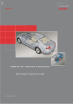
adaptive air suspension
in the Audi A8
Home study program 292
All rights reserved, including the right to
make technical changes
Copyright* 2002 AUDI AG, Ingolstadt
Department I/VK-35
D-85045 Ingolstadt
Fax +49 (0)841/89-36367
000.2811.12.20
Technically correct as at 007/02
Printed in Germany
For internal company use only
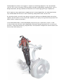
The development of the running gear is subject to conflicting objectives. For now, besides
"classic" aims such as function, driving safety, strength and durability, requirements such as
weight reduction, driving comfort and acoustics are increasingly gaining in importance.
At first glance, many requirements appear to be in mutual opposition. A car designed to be
very comfortable will lose out in terms of driving safety when driven at the limit.
On the other hand, a car with very sporty tuning will achieve considerably higher cornering
speeds, and will reach its limit much later. However, this sporty tuning necessarily entails limitations when it comes to comfort.
In the Audi A8 MY 2003, a newly developed, fully bearing air suspension system is used.
In conjunction with the CDC status-dependent electronic damping control, this ensures that
the main - and partly conflicting - requirements are satisfied in an optimum manner within the
limits of the laws of physics.
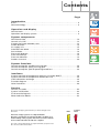
Contents
Page
Introduction
Basics . . . . . . . . . . . . . . . . . . . . . . . . . . . . . . . . . . . . . . . . . . . . . . . . . . . . . . . . . . . . . . 4
New technology. . . . . . . . . . . . . . . . . . . . . . . . . . . . . . . . . . . . . . . . . . . . . . . . . . . . . . 4
Operation and display
Vehicle levels . . . . . . . . . . . . . . . . . . . . . . . . . . . . . . . . . . . . . . . . . . . . . . . . . . . . . . . . 6
Operation and display system . . . . . . . . . . . . . . . . . . . . . . . . . . . . . . . . . . . . . . . . . . 9
System components
Vehicle overview . . . . . . . . . . . . . . . . . . . . . . . . . . . . . . . . . . . . . . . . . . . . . . . . . . . .
Control unit J197 . . . . . . . . . . . . . . . . . . . . . . . . . . . . . . . . . . . . . . . . . . . . . . . . . . . .
Suspension/shock absorber strut . . . . . . . . . . . . . . . . . . . . . . . . . . . . . . . . . . . . . .
Shock absorber . . . . . . . . . . . . . . . . . . . . . . . . . . . . . . . . . . . . . . . . . . . . . . . . . . . . .
Air supply unit . . . . . . . . . . . . . . . . . . . . . . . . . . . . . . . . . . . . . . . . . . . . . . . . . . . . . .
Solenoid valve block . . . . . . . . . . . . . . . . . . . . . . . . . . . . . . . . . . . . . . . . . . . . . . . . .
Accumulator. . . . . . . . . . . . . . . . . . . . . . . . . . . . . . . . . . . . . . . . . . . . . . . . . . . . . . . .
Pneumatic diagram . . . . . . . . . . . . . . . . . . . . . . . . . . . . . . . . . . . . . . . . . . . . . . . . . .
Pressure build-up. . . . . . . . . . . . . . . . . . . . . . . . . . . . . . . . . . . . . . . . . . . . . . . . . . . .
Pressure reduction . . . . . . . . . . . . . . . . . . . . . . . . . . . . . . . . . . . . . . . . . . . . . . . . . .
Senders (sensors) . . . . . . . . . . . . . . . . . . . . . . . . . . . . . . . . . . . . . . . . . . . . . . . . . . .
10
12
13
14
15
16
16
18
19
19
20
System functions
Control concept for standard running gear . . . . . . . . . . . . . . . . . . . . . . . . . . . . . . 26
Control concept for sporty running gear . . . . . . . . . . . . . . . . . . . . . . . . . . . . . . . . 28
Control concept for special operating conditions . . . . . . . . . . . . . . . . . . . . . . . . . 29
Interfaces
System overview of components with bus link (CAN, MOST) . . . . . . . . . . . . . . .
System overview of components without bus link . . . . . . . . . . . . . . . . . . . . . . . .
CAN information exchange . . . . . . . . . . . . . . . . . . . . . . . . . . . . . . . . . . . . . . . . . . .
Function diagram . . . . . . . . . . . . . . . . . . . . . . . . . . . . . . . . . . . . . . . . . . . . . . . . . . .
Other interfaces . . . . . . . . . . . . . . . . . . . . . . . . . . . . . . . . . . . . . . . . . . . . . . . . . . . . .
34
35
36
38
40
Service
Control unit code . . . . . . . . . . . . . . . . . . . . . . . . . . . . . . . . . . . . . . . . . . . . . . . . . . . .
System initialisation . . . . . . . . . . . . . . . . . . . . . . . . . . . . . . . . . . . . . . . . . . . . . . . . .
Final control diagnosis . . . . . . . . . . . . . . . . . . . . . . . . . . . . . . . . . . . . . . . . . . . . . . .
Measured value blocks . . . . . . . . . . . . . . . . . . . . . . . . . . . . . . . . . . . . . . . . . . . . . . .
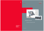
The home study program informs you about designs and
functions.
New!
42
42
43
43
Caution!
Note!
The home study program is not a Repair Manual!
All values stated herein are purely intended to facilitate your
understanding of the program, and are based on the software
version valid at the time the SSP was compiled.
For service and repair work, it is important that you please use
the current technical literature.
3
Introduction
Basics
The basics for understanding air suspension
systems are contained in home study programs 242 and 243 and are of course also
valid for the system to be introduced in the
A8 from model year 2003.
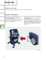
New technology
The new A8 heralds a new system in terms of
technical content and range of functions. It
differs from the known system of the allroad
quattro in the following features:
292_001
CDC instead of PDC damping control:
The control takes account of the current driving status. The wheel movements (unsprung
masses) and body movements (sprung
masses) are recorded.
Within the choice of four programs (modes),
different
damping
characteristics
are
implemented. In this process, each shock
absorber can be controlled independently.
Therefore, in each mode which is selected
(comfortable or sporty), the maximum degree
of comfort and driving safety is ensured (see
description "Shock absorber" in the "System
components" section).
The term "mode" can therefore be understood
to be the well-balanced combination of the
adaptive air suspension program and the
damping map.
Enhanced sensor system:
Three acceleration sensors are employed to
record the body movement.
(See description "Body acceleration sender"
in the "System components" section.)
292_025
4
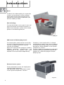
Encased pneumatic springs:
The air bellows are encased in an aluminium
cylinder. The result is a considerable improvement in the response characteristic.
(See description "Pneumatic springs" in the
"System components" section.)
292_003
Operation:
Integration in the MMI means that operation
is user-friendly, logical and easy to learn.
(See description in the "Operation and display" section.)
292_002
Residual pressure retaining valves:
Each suspension strut features residual pressure retaining valves directly at the air connection. This ensures that a minimum pressure of approx. 3.5 bar is maintained in the pneumatic
springs. This practically eliminates the risk of damage during storage and assembly to the
greatest possible extent.
5
Operation and display
Vehicle levels
The A8 comes either with a standard running gear (adaptive air suspension) or a sporty running gear (adaptive air suspension-sport).
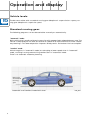
Standard running gear:
The following programs can be selected either manually or automatically:
"automatic" mode:
Basic vehicle level, comfort-oriented suspension with appropriately adapted damper map. The
vehicle is lowered by 25 mm after 30 seconds at speeds of 75 mph (120 km/h) or more ("motorway lowering"). This lowered position improves aerodynamics and reduces fuel consumption.
"comfort" mode:
Vehicle height as in "automatic" mode, less damping at lower speeds than in "automatic"
mode, resulting in even greater driving comfort than in "automatic" mode.
There is no automatic motorway lowering.
Basic level
of standard
running
gear
"automatic" and "comfort" mode: Basic level
6
292_005
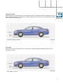
"dynamic" mode:
Vehicle level is 20 mm lower than in "automatic" mode. The damper map is automatically set to
sporty. After 30 seconds at speeds of 75 mph (120 km/h) or more, the car is lowered by another
5 mm ("motorway lowering").
- 20 mm
"dynamic" mode: - 20 mm
292_004
"lift" mode:
Vehicle level is 25 mm higher than in "automatic" mode, comfort-oriented suspension like
"automatic" mode.
+ 25 mm
"lift" mode: + 25 mm
292_006
7
Operation and display
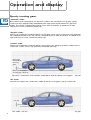
Sporty running gear:
"automatic" mode:
Basic vehicle level corresponds to "dynamic" mode in the standard running gear, sporty
suspension with appropriately adapted damper map (more comfortable than "dynamic"
mode). The vehicle is lowered by another 5 mm after 30 seconds at speeds of 75 mph
(120 km/h) or more ("motorway lowering").
"dynamic" mode:
Level as for "automatic" mode of sporty running gear, hard, sporty suspension with appropriately adapted damper map. The vehicle is lowered by 5 mm after 30 seconds at speeds of 75
mph (120 km/h) or more ("motorway lowering").
"comfort" mode:
Level as for "automatic" mode of sporty running gear, less damping at lower speeds than in
"automatic" mode. There is no automatic motorway lowering.
Basic level
of standard
running
gear
Basic level of sporty
running gear (-20 mm)
"dynamic", "automatic" and "comfort" mode: Basic level for sporty running gear
292_049
"lift" mode:
Level 25 mm higher than "automatic" mode of sporty running gear, sporty suspension.
+ 25 mm
"lift" mode: + 25 mm
8
292_006
Operation and display system
The process of switching from one mode to
another and the display/monitoring of the
system status all form part of the MMI operating system.
The adaptive air suspension menu is opened
directly in the MMI display in the centre console when the "CAR" button is pressed. This
ensures that adaptive air suspension has first
priority. This means that any other functions
already in the display are blanked out in
favour of the adaptive air suspension operating/status display.
Turning the control knob to a different mode
and then pressing the control knob activates
a new mode.
System status information can be requested
and special settings undertaken by pressing
the SETUP button.
(See current Owner’s Manual and "Control
strategy" in the "Special system states" section.)
292_010
With the standard running gear, the
"dynamic" mode (low level) is additionally displayed as driver information by an indicator
lamp in the dash panel insert.
An extremely low or extremely high level is
displayed by the indicator lamp and the warning lamp in the dash panel insert.
(See "Control strategy" in "Special system
states".)
Warning
lamp
292_011
Indicator lamp for
extreme low level
9
System components
Vehicle overview
Dash panel insert
Front operator/display unit
(MMI)
Adaptive air suspension
control unit
Body acceleration
sender
Pneumatic struts, FA
Vehicle level
sender, FA
Solenoid valve block
with pressure sender
Air supply unit
10
Body acceleration sender
Pneumatic struts, RA
Accumulator
Vehicle level sender, RA
292_012
11
System components
Control unit J197
The control unit is the central element of the
system. It is installed in the vehicle in front of
the glove box.
It processes the relevant messages from the
other bus users, and the discreet input signals (see function diagram and CAN information exchange).
The principal result of this processing work
are the signals to actuate the compressor, the
solenoid valves and the shock absorbers.
Because of the differences between the
standard and sporty running gears, the control unit had to be produced in two versions
(software application).
292_013
Hardware
4E0 907 553 C *
4E0 907 553 D *
= Standard running gear
= Sporty running gear
Software
4E0 910 553 C *
4E0 910 553 D *
= Standard running gear
= Sporty running gear
* These numbers are correct as at 06/2002. Changes may be made as a result of further
technical developments.
(See current Repair Manual.)
12
Suspension/shock absorber strut
All four suspension/shock absorber struts are constructed in the same way.
Pneumatic spring
Construction:
The pneumatic spring is encased in an aluminium cylinder. In order to prevent dirt from
getting between the cylinder and the air bellows, the area between the piston and the cylinder is sealed by a sleeve. The sleeve can be
replaced during servicing, but the air bellows
cannot be replaced separately. In the event of
a fault, the entire suspension/shock absorber
strut must be replaced.
In order to provide as much usable space and
loading width in the boot as possible, the
diameter of the rear axle pneumatic springs is
kept to a minimum. However, if demands for
comfort are to be met, a minimum air volume
is required. The solution to this conflict is provided in the form of a reservoir for additional
air, which is connected to the shock absorber.
Aluminium
cylinder
Pneumatic
spring
Suspension/
shock absorber
strut, front axle
292_014
Additional
air volume
Function:
The pneumatic spring not only replaces the
steel spring, it also offers considerable
advantages over the steel version (see
SSP 242). Encasing the pneumatic spring in
an aluminium cylinder enables the wall thickness of the bellows to be reduced. This
results in an even more sensitive response to
bumpy roads.
Suspension/
shock absorber
strut, rear axle
292_015
13
System components
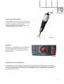
Shock absorber
Construction:
A twin-tube gas-filled shock absorber with
continuous electrical control is used (ccontinuous damping control =CDC shock absorber).
The main damping valve 3 in the piston 1 is
mechanically pre-tensioned by a spring 4. A
solenoid 5 is situated above the valve, and the
connecting cable is routed to the outside
through the hollow piston rod.
Function:
For general information on the function of a
twin-tube gas-filled shock absorber, see
SSP 242.
The damping force is determined to a considerable extent by the flow resistance of the
valves. The greater the flow resistance for the
oil flowing through the valves, the higher the
damping force.
Basic method of operation using bump as an example (= bump absorption):
292_016
The entire piston unit 1 is moved downwards
inside the cylinder tube 2 at speed v.
The oil pressure in the chamber below the
main damping valve 3 increases.
Current flows to the solenoid 5. The magnetic
force FM counteracts the spring force FF and
partially raises it.
If the sum of the magnetic force and the oil
pressure force (FM+FP) exceeds the spring
force FF, the resulting force FR opens the
valve. The amount of magnetic force can be
regulated by adjusting the amount of electrical current. The higher the electrical current,
the lower the flow resistance and thus the
damping force.
Info: The highest damping force is achieved when the solenoid is not electrically actuated.
For the lowest damping force, the solenoid must be receiving a current of approx.
1800 mA.
In emergency running mode, the solenoid is not electrically actuated. In this way, the
damping force is set to maximum, ensuring a dynamically stable driving condition.
14
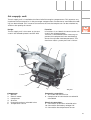
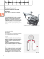
Air supply unit
The air supply unit is installed at the front left of the engine compartment. This prevents any
impairment of the acoustics in the passenger compartment. Furthermore, more effective cooling can be achieved. This increases the amount of time the compressor can be switched on,
and thus the quality of control.
Design:
The air supply unit is the same as the one
used in the allroad quattro (see SSP 243).
10
Function:
It functions in an identical manner to the unit
used in the allroad quattro.
The unit is switched off when necessary to
prevent the compressor from overheating
(excessive cylinder head temperature). The
maximum static system pressure is 16 bar.
1
2
3
9
11
8
5
4
6
Components:
1. Bracket
2. Electric motor
3. Compressor
4. Air drier
5. Pneumatic exhaust solenoid valve
6. Temperature sensor
7
292_017
Pneumatic connections:
7. Air intake and exhaust line
8. Compressed air connection to solenoid
valve block
Electrical connections:
9. Connection to exhaust solenoid valve
10. Connection for battery voltage 12V
11. Connection for temperature sensor
15
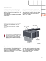
System components
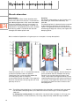
Solenoid valve block
Solenoid valves
The solenoid valve block contains the pressure sender and the valves for actuating the
pneumatic springs and the accumulator. It is
installed in the wheel housing between the
wheel housing liner and the left-hand
A-pillar.
Construction/function:
The construction and function of the solenoid
valves are largely the same as in the allroad
quattro (see SSP 243).
Pressure connection
for compressor
Front right
Front left
Rear left
Accumulator
Rear right
292_018
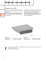
Accumulator
The accumulator is situated between the
floor of the boot and the rear silencer on the
left-hand side of the vehicle.
Construction:
The accumulator is made of aluminium.
It has a volume of 5.8l and a max. operating
pressure of 16 bar.
Function:
The objective in designing this system was to
reliably satisfy functional requirements
whilst keeping energy consumption to a minimum (so that the compressor is on as little
as possible). In order to enable controlled
pressure build-up to be effected solely with
the accumulator, there must be a minimum
difference in pressure of 3 bar between the
accumulator and the pneumatic springs.
16
292_019
Notes
17
System components
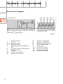
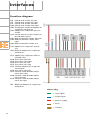
Pneumatic diagram
Air supply unit
Solenoid valve block
292_020
1
Compressor V66
2
Air drier
3a, 3b Non-return valves
4
Exhaust throttle
5
Electrical exhaust solenoid valve
N111
6
Pneumatic exhaust solenoid valve
7
Additional silencer
8
Air filter
9a
Valve for strut FL N148
9b
Valve for strut FR N149
18
9c
9d
10
11
12
13a
13b
13c
13d
Valve for strut RL N150
Valve for strut RR N151
Valve for accumulator N311
Pressure sender G291
Accumulator
Pneumatic spring FL
Pneumatic spring FR
Pneumatic spring RL
Pneumatic spring RR
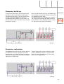
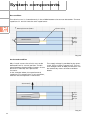
Pressure build-up
The valves 9a, 9b and 9c, 9d are electrically
actuated in pairs (front axle and rear axle).
The compressor takes in the air through the
air filter 8 and the additional silencer 7.
The compressed air flows via the air drier 2,
the non-return valve 3a and the valves 9 to the
pneumatic springs.
When the pneumatic springs are filled by the
accumulator, the valve 10 and the valves 9 for
the appropriate axle open.
The accumulator 12 is filled by the compressor 1 forcing air through the open valve 10.
If the vehicle is on a sideways incline, valves
9a - 9d are also actuated individually.
292_021
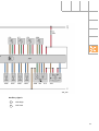
Pressure reduction
The appropriate valves 9a, 9b and 9c, 9d and
the electrical exhaust solenoid valve 5 are
opened. The air can flow through the exhaust
solenoid 5 to open the pneumatic, pilot operated exhaust solenoid 6.
The air leaves the system via exhaust solenoid 6, additional silencer 7 and air filter 8.
When air flows through the air drier 2, the
desiccant is regenerated.
292_022
19
System components
Senders (sensors)
Compressor temperature sender G290
Construction:
An NTC resistor is housed in a small glass
case.
Function:
The sender records the temperature of the
cylinder head compressor.
Its resistance decreases sharply as the temperature rises (NTC: negative temperature
coefficient). This change in resistance is analysed by the control unit. The current temperature calculated in each case determines the
maximum compressor running time. The
sender cannot be replaced separately during
servicing.
Temperature sensor
292_017
Pressure sender G291
Construction:
The sender is cast in the solenoid valve block
and is inaccessible from the outside.
Function:
The pressure sender measures the pressure
of the front and rear axle struts or the accumulator (depending on how the solenoid
valves are actuated, see pneumatic diagram).
The G291 employs a capacitive measuring
technique:
The pressure (p) to be measured causes a
ceramic diaphragm to deflect. This deflection
changes the distance between an electrode
(1) attached to the diaphragm and a stationary counter-electrode (2) on the sender housing.
The electrodes together form a capacitor. The
smaller the distance between the electrodes,
the greater the capacitance of the capacitor.
This capacitance is measured by the integrated electronics and converted to a linear
output signal.
20
P
2
1
292_024
Acceleration sender
In order to achieve optimum damping for
every driving condition, knowledge of the
body movement (sprung mass) and axle components (unsprung mass) characteristic over
time is required.
The acceleration of the body is measured by
three senders.
Two of these are situated on the front axle
MacPherson strut towers, the third in the rear
right wheel housing. The acceleration of the
axle components (unsprung masses) is determined by evaluating the signals from the
vehicle level senders.
Body acceleration senders G341, G342, G343
The senders are bolted to the body with
brackets.
The senders and brackets are crimped
together.
Cable outlet
Tabs for crimp
The crimp must not be tampered with!
During service work, the sender must
always be replaced together with the
bracket. When installed correctly, the
arrow on the sender housing must point
upwards!
Arrow for
installation
position
Bracket
292_025
Construction:
The sender element consists of several layers
of silicon and glass. The middle silicon layer
takes the form of a spring-loaded reed (seismic mass). The sensitivity of the sender is
predominantly determined by the spring rate
and the mass of the reed.
Function:
The metal-coated seismic mass acts as a moving electrode which, together with the upper
and lower counter-electrodes, forms capacitors. The capacitance of these is dependent
upon the electrode surfaces and their distance from one another.
21
System components
Rest condition:
The seismic mass is situated exactly in the middle between the counter-electrodes. The two
capacitors C1 and C2 have the same capacitance.
*
*
Metal-plated electrodes
Seismic mass
Silicon spring
Capacitor C1
Capacitor C2
292_026
Accelerated condition:
Mass inertia causes the seismic mass to be
deflected from its central position. The distance between the electrodes changes. As the
distance is reduced, the capacitance
increases.
In the example below, the capacitance of
capacitor C2 is greater than in rest condition,
whereas that of capacitor C1 decreases.
The supply voltage is provided by the pneumatic spring system’s control unit. The current voltage values of body acceleration can
be read out by means of measured data
blocks.
Acceleration
Capacitor C1
Seismic mass
Capacitor C2
292_027
22
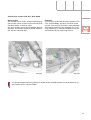
Vehicle level senders G76, G77, G78, G289
Construction:
The sender construction and the PIN designation are the same as those of the allroad quattro (description in SSP no. 243).
The four senders are interchangeable, but the
brackets and coupling rods must be fitted to
the correct side and axle.
292_028
Function:
The senders record the distance between the
links and the body, and thus the level of the
vehicle. The sensing function is now effected
with 800 Hz (200 Hz in the allroad). This scanning frequency is sufficient to determine the
acceleration of the unsprung masses.
292_034
Installing the geometrically identical sender of the allroad quattro in the A8 leads to system failure and is not permitted.
23
System functions
General control concept
Changes in level are effected by axle, with correction of differences in level between the left
and right-hand sides (e.g. caused by one-sided loading of the vehicle)
At vehicle speeds of 22 mph (35 km/h) or less, the accumulator is the preferred energy source.
A prerequisite for this is a pressure difference of at least 3 bar between the accumulator and
the pneumatic springs.
Level change procedure:
Lifting:
First the rear axle is lifted, then the front axle
Lowering:
First the front axle is lowered, then the rear
axle
Lifting
Lowering
292_029
This sequence ensures that oncoming traffic will not be dazzled during levelling operations,
even in the event of failure of the headlight range control.
Headlight range control is only employed in vehicles with Xenon headlights.
24
Notes
25
System functions
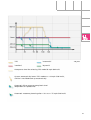
Control concept for standard running gear
"automatic" mode (basic level)
The suspension is oriented towards a more comfortable ride.
Automatic motorway lowering of 25 mm takes place after 30 seconds at speeds of 75 mph
(120 km/h) or more.
The vehicle is automatically lifted back up to basic level once the speed drops below 44 mph
(70 km/h) for 120 seconds or if the speed drops below 22 mph (35 km/h).
"dynamic" mode (-20 mm)
Here, a taut damping map is applied to the vehicle’s entire speed range.
When the vehicle speed exceeds 75 mph (120 km/h) for 30 seconds, the vehicle is automatically lowered by a further 5 mm (motorway).
The vehicle is automatically lifted back to the sporty level once the speed drops below 44 mph
(70 km/h) for 120 seconds or if the speed drops below 22 mph (35 km/h).
"comfort" mode (basic level)
The suspension is even more comfort-oriented than in "automatic" mode, particularly at lower
speeds.
There is no automatic motorway lowering.
"lift" mode (+25 mm)
This mode can only be selected at speeds of less than 50 mph (80 km/h).
The controller automatically leaves this mode at speeds of 63 mph (100 km/h). It then reverts
to the mode which was previously selected ("automatic", "dynamic" or "comfort").
Even if the speed again drops below 50 mph (80 km/h), the "lift" mode is not automatically
adopted.
26
"lift"
"automatic"
"comfort"
"dynamic"
292_053
Acceptance level for selecting "lift" mode 50 mph (80 km/h)
System automatically leaves "lift" mode at v > 63 mph (100 km/h),
vehicle is not lifted back up automatically
Automatic lift to revert to sporty/basic level
(dependent on speed/time)
Automatic motorway lowering after > 30 s at v > 75 mph (120 km/h)
27
System functions
Control concept for sporty running gear
Differences from the standard running gear:
– Different, sporty suspension and damping
– Same levels but different damping maps
for "dynamic", "automatic" and "comfort"
modes at speeds of less than 75 mph
(120 km/h)
– Basic vehicle level 20 mm lower than with
standard running gear
292_052
"lift"
"automatic"
"comfort"
"dynamic"
Basic level of
standard running gear
Acceptance level for selecting "lift" mode 50 mph (80 km/h)
System automatically leaves "lift" mode at v > 63 mph (100 km/h),
vehicle is not lifted back up automatically
Automatic lift to revert to sporty level
(dependent on speed/time)
Automatic motorway lowering after > 30 s at v > 75 mph (120 km/h)
28
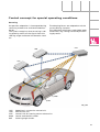
Control concept for special operating conditions
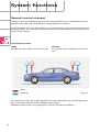
Cornering
Suspension adaptation is interrupted during
cornering manoeuvres and continued afterwards.
The system recognises that cornering is taking place by means of the signals from the
steering angle and lateral acceleration senders.
The damping forces are adapted to suit the
current driving situation.
This effectively eliminates undesirable body
movements (e.g. rolling) caused by the driving dynamics.
J197
J104
J527
G200
G85
292_044
J107
J104
J527
G200
G85
Adaptive air suspension control unit
ESP control unit
Control unit for steering column electronics
Lateral acceleration sender
Steering angle sender
29
System functions
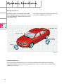
Braking manoeuvres
Damping control is employed, particularly
during ABS/ESP braking manoeuvres. Damping is regulated as a function of the current
braking pressure.
This keeps nose diving, squatting and rolling
of the vehicle body to a minimum.
Longitudinal axis
Transverse axis
Squatting/
nose diving
Rolling
292_033
Starting manoeuvres
During starting manoeuvres, the mass inertia of the body leads above all to squatting.
Appropriate damping forces that are adapted to the current situation restrict these movements to a minimum.
30
Pre-travel and after-run mode
Any difference from the specified height
before driving commences or before ignition
on is corrected.
When the door, boot lid or terminal 15 is
actuated, the system is woken from sleep
mode and goes into pre-travel mode (see section on Interfaces).
Any difference in height caused, for example,
by climbing out of or unloading the vehicle
after switching off the ignition, is corrected in
after-run mode.
Sleep mode
After 60 seconds in after-run mode without
receiving an input signal, the system goes
into the energy-saving sleep mode. The system leaves sleep mode briefly after 2, 5 and
10 hours to check the height level again.
Any difference in height from the specified
value (e.g. due to the cooling of the air in the
pneumatic springs) is corrected by the accumulator.
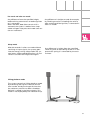
Lifting-platform mode
The system recognises lifting-platform mode
by evaluating the signals from the vehicle
level sender and by the length of time that
the stationary vehicle has been shutdown.
No fault is stored in the fault memory. This
mode is not displayed by the indicator lamp.
292_034
31
System functions
Using a jack (service mode)
There is no automatic recognition.
Adaptive air suspension must be deactivated if a jack is to be used. This is done by actuating
the MMI control knob in the CAR -> SETUP menu.
This mode is deactivated either by resetting in MMI or by driving at a speed of >9 mph
(15 km/h).
Address book
Settings
Setup Car
adaptive air suspension
Manual
Trailer mode
off
Jacking mode
off
TP
TMC Intercom
Tone
292_036
Trailer mode
Trailer mode is recognised automatically when the trailer is electrically connected to the towing vehicle.
The system status (trailer mode on or off) can be requested by means of the SETUP button
and activated if necessary using the MMI control knob.
In the standard running gear, "dynamic" mode cannot be selected in trailer mode.
Address book
Settings
Setup Car
adaptive air suspension
Manual
32
Trailer mode
off
Jacking mode
off
TP
TP
TMC Intercom
Tone
292_035
Extreme low level
Extreme low level (65 mm or more below normal level) is shown by the low level indicator
lamp and the warning lamp flashing. Extreme
low level can occur after the vehicle has been
at a standstill for a very long period.
292_045
Extreme high level
Extreme high level (50 mm or more above
normal level) is shown by the warning lamp
flashing. Extreme high level may occur briefly
when heavy objects are unloaded.
292_046
Emergency running function
If a failure of system components or signals
is detected, the full functional reliability of
the system is generally no longer guaranteed.
Therefore, depending on the severity of the
fault, an emergency running program is
started.
Faults are stored in the fault memory.
The warning lamp in the dash panel insert
comes on.
The premise for emergency running mode is
the maintenance of driving stability. Excessively soft suspension is prevented. In the
event of complete failure of the system control, the damper actuation is de-energized
and the system is set to hard suspension.
(See "Shock absorber" description in the "System components" section)
33
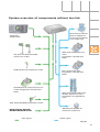
Interfaces
System overview of components with bus link (CAN, MOST)
J197 Adaptive air
suspension control
unit
Diagnosis
J533 Gateway
J285 Control unit with
display unit in dash
panel insert
J345 Trailer
recognition control
unit
J220 Motronic control
unit
J518 Access and start
authorisation control
unit
CAN drive
CAN multi-function
MOST bus
J104 ESP control unit
CAN comfort
Diagnostic CAN
J523 Control unit for
front operating and
display unit
J431 Control unit for
headlight range
control
J527 Control unit for
steering column
electronics, G85
steering angle sender
34
292_038
System overview of components without bus link
N111 Exhaust solenoid
valve for adaptive air
suspension (integrated
in air supply unit)
CAR button
SETUP button
G76, G77, G78, G289 FA and RA
vehicle level senders
G290 Compressor temperature sender
G291 Adaptive air suspension pressure
sender (integrated in solenoid valve
block)
N148, N149, N150, N151 Strut
valves
(integrated in solenoid valve
block)
N311 Accumulator valve
(integrated in solenoid valve
block)
N336, N337, N338, N339 Shock
absorber adjustment valves
(integrated in the appropriate
strut)
G341, G342, G343 Body acceleration senders
Ancillary signals: Signal for
door/bonnet/boot lid contact
Input signals
J403 Relay for adaptive air
suspension compressor
Output signals
292_050
35
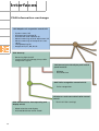
Interfaces
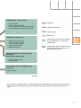
CAN information exchange
J197 Adaptive air suspension control unit
–
–
–
–
–
System status (all)
Actuate warning lamp (5)
Actuate low level indicator (5)
Advance warning of level adjustment (4)
Advance warning of compressor startup (4)
– Lifting/lowering (4)
– Height of FR, FL, RR, RL (4)
J533 Gateway
– Reversing light On/Off
– Current status of mileage, time, trailer
recognition signals
J285 Control unit with display unit in dash
panel insert (5)
– Mileage
– Date and time
J345 Trailer recognition control unit (6)
– Trailer recognition
J518 Access and start authorisation control
unit (7)
J523 Control unit for front operating and
display unit (8)
– Mode selection and display
– Activate/deactivate trailer mode
36
– Terminal X (for starting)
J220 Motronic control unit (1)
–
–
–
–
Engine speed
Driver’s desired torque
Current position of brake light switch
Current position of brake test switch
CAN drive
CAN multi-function
CAN comfort
MOST bus
J104 ESP control unit (2)
–
–
–
–
–
Information which is transmitted
by the adaptive air suspension
control unit
ABS braking activated
ESP override activated
Current vehicle speed
Lateral acceleration
Braking pressure
Information which is received and
evaluated by the adaptive air suspension control unit
J527 Control unit for steering column
electronics
G85 Steering angle sender
– Steering wheel angle
– System status
J431 Control unit for headlight range
control (4)
(receiver only)
292_038
The numbers in brackets after the message content designate the control unit that processes
the information in question: e.g.: Activate warning lamp is processed by control unit no. 5,
J285.
37
Interfaces
Function diagram
G76
G77
G78
G289
G290
G291
J393
G341
G342
G343
Vehicle level sender, rear left
Vehicle level sender, rear right
Vehicle level sender, front left
Vehicle level sender, front right
Temperature sender for adaptive air
suspension compressor
Adaptive air suspension pressure
sender
Central control unit for comfort system (for door signal)
Body acceleration sender, front left
Body acceleration sender, front
right
Body acceleration sender, rear
J197 Adaptive air suspension control
unit
J403 Relay for adaptive air suspension
compressor
N111 Adaptive air suspension exhaust
solenoid valve
N148 Strut valve, front left
N149 Strut valve, front right
N150 Strut valve, rear left
N151 Strut valve, rear right
N311 Valve for adaptive air suspension
accumulator
N336 Strut valve, front left
N337 Valve for shock absorber adjustment, front right
N338 Valve for shock absorber adjustment, rear left
N339 Valve for shock absorber adjustment, rear right
V66
Motor for adaptive air suspension
compressor
Colour coding
= input signal
= output signal
= positive supply
= earth
= CAN bus
38
8
292_051
Ancillary signals
1
CAN High
2
CAN Low
39
Interfaces
Other interfaces
The wake-up signal
to wake the adaptive air suspension control
unit from sleep mode is transmitted by the
comfort system central control unit J393.
It uses a pulse-width-modulated signal.
The duration of the signal pulse varies
depending on whether the doors and/or boot
lid are opened or closed.
J393 transmits a signal even if terminal 15 is
detected but the doors and/or boot lid are
not opened or closed.
292_047
40
The signal for headlight range control
The adaptive air suspension control unit
sends the headlight range control unit a CAN
message about the momentary body level on
all four wheels.
The headlight range control unit uses this
information to calculate the required headlight setting in each case.
The terminal X signal
Loads that consume a lot of power are briefly
switched off during the starting process. This
applies to the compressor of the adaptive air
suspension system.
Information about terminals 15 and 50 is sent
to the access and start authorisation control
unit J518 via discrete lines from the access
and start authorisation switch E415.
The J518 transmits the terminal X message
via CAN bus to the adaptive air suspension
control unit.
This then prevents the compressor from running whilst the terminal 15/terminal 50 message is valid.
41
Service
Control unit code
The code for both the standard and the sporty running gear is 15500.
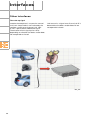
System initialisation
The system initialisation process includes calibration of the vehicle level senders.
This is required whenever a sender or the
control unit is replaced.
System initialisation is performed using diagnostic tester VAS 5051(address word: 34 –
adaptive air suspension).
The height of each wheel is measured from
the centre of the wheel to the lower edge of
the wheel housing.
The measured values are transmitted one
after the other to the control unit by means of
function 10, "Adaptation". The specified
dimensions are stored in the control unit. The
correction factors can be determined by comparing the specified values with the measured values.
292_041
42
Final control diagnosis
Final control diagnosis checks the function of
the compressor, the solenoid valves and the
struts/shock absorbers.
Diagnosis is executed automatically in three
steps.
Final control diagnosis is implemented when
the vehicle is stationary and the ignition is on.
The engine may be running. During final control diagnosis, the yellow warning lamp in the
dash panel insert flashes.
1. Test of each individual strut by lowering it
20 mm below its current level for a period
of 30 seconds
2. Charge and empty the accumulator
3. Variation of electrical currents to actuate
the shock absorbers
Each of the three steps may be selected separately (selective final control diagnosis).
Measured value blocks
The most important information about the
system status are stored in the measured
value blocks.
Detailed information on system initialisation,
final control diagnosis, measured value
blocks and control unit coding can be found
in the fault finding guide.
43
Notes
44
292
292
Service
adaptive air suspension
in the Audi A8
Home study program 292
All rights reserved, including the right to
make technical changes
Copyright* 2002 AUDI AG, Ingolstadt
Department I/VK-35
D-85045 Ingolstadt
Fax +49 (0)841/89-36367
000.2811.12.20
Technically correct as at 007/02
Printed in Germany
For internal company use only