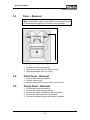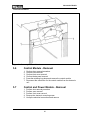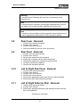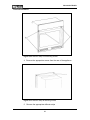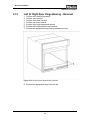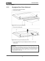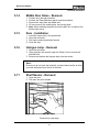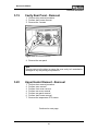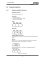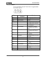
1
Novotronic Models
Technical Information
TECHNICAL INFORMATION
H350, H373 &H387 Ovens
© 2004 Miele
1
Novotronic Models
Technical Information
Table of Contents – H350, H373 & H387 Ovens
010 – Construction and Design
1
Unit Overview H350
2
Unit overview H373/H387
3
Data Tag Information
5
6
7
020 – Installation Information
1
Electrical Information
10
030 – Commissioning and Operation
1
Before Using For the First Time
2
Controls – Basic Overview
3
Cooking Using Default Temperatures
4
Rapid Heat
5
Turning Off Rapid Heat
6
Selector Switch
11
12
14
15
15
16
040 – Function and Description
1
Cooling Fan Run-On
2
Catalyser System
3
Pyrolitic/ Self- Cleaning
4
Catalyser
5
Door Lock Mechanism
6
Safety Cut-Out
7
Rapid Heat
8
Door Switch
9
Temperature Sensor
10
Automatic Door Lock
11
Door Contact Switch
12
Control and Power Electronic
18
19
20
22
24
25
25
26
26
26
26
27
2
Novotronic Models
Technical Information
Table of Contents – Continued
050 – Service and Maintenance
1
Layout of Electrical Components
2
Service
5.2
Door Removal
5.3
Oven Removal
5.4
Front Cover Removal
5.5
Fascia Panel Removal
5.6
Control Module Removal
5.7
Control and Power Module Removal
5.8
Rear Cover Removal
5.9
Rear Panel Removal
5.10
Left or Right Side Panel Removal
5.11
Left or Right Deflector Strip Removal
5.12
Left or Right Hinge Bearing Removal
5.13
Cleanglass Door Panel Removal
5.14
Middle Door Glass Removal
5.15
Door Installation
5.16
Halogen Lamp Removal
5.17
Shelf Runner Removal
5.18
Reflector and Glass Cover Removal
5.19
Cavity Rear Panel Removal
5.20
Upper Heating Element Removal
5.21
Lower Heating Element Removal
5.22
Oven Temperature Sensor Removal
5.23
Temperature Regulator Removal
5.24
Convection Heating Element Removal
5.25
Convection Heating Fan Removal
5.26
Fumes Extractor Removal
5.27
Cooling Fan Removal
5.28
Catalyser Removal
5.29
Catalyser Temperature Sensor Removal
5.30
Door Latch Release
5.31
Door Lock Cable Removal
5.32
Door Switch Removal
5.33
Door Locking Device Removal
5.34
Pyrolitic Temperature Regulator Removal
5.35
Door Lock Manual Override
3
29
34
34
35
35
35
36
36
37
37
37
37
39
40
41
41
41
41
42
43
43
45
45
46
47
48
48
48
49
49
50
50
51
51
52
53
Novotronic Models
Technical Information
Table of Contents – Continued
060 – Fault Diagnosis
1
Service Modes
2
Fault Codes
6.2.1
Fault Code F3
6.2.2
Fault Code F4
6.2.3
Fault Code F5
6.2.4
Fault Code F6
6.2.5
Fault Code F9
6.2.6
Fault Code F13
6.2.7
Fault Code F14
6.2.8
Fault Code F15
6.2.9
Fault Code F16
6.2.10 Fault Code F17
3
Fault Repair
6.3.1
Excessive Noise During Fan Operation
6.3.2
Selected Temperature Exceeded
6.3.3
Excessive Noise During Cooling Fan Operation
6.3.4
Misting of Interior Door Panel
6.3.5
Misting Behind Display
6.3.6
Unit Does Not Heat
6.3.7
Self Cleaning (Pyrolitic Mode) Cannot be Switched Off
6.3.8
Programming Operating Parameter, Voltage and Frequency
6.3.9
Programming Model Variant Display
6.3.10 Electronic Version Display
6.3.11 Cooling Fan Activation Hi
6.3.12 Cooling Fan Activation Low
6.3.13 Convection Fan Activation Max
6.3.14 Convection Fan Activation Min
6.3.15 Oven Lights Activation
6.3.16 Display Check
6.3.17 Buzzer Activation
6.3.18 Roast Probe Temperature
6.3.19 Cooling Fan Activation at Pyrolitic Cleaning Speed
6.3.20 Door Lock Activation
6.3.21 Demonstration Mode Activation
6.3.22 Demonstration Mode Deactivation
6.3.23 Fault Codes Retrieval and Deletion
6.3.24 Operating Hours (Fan Heat and Auto Roast)
6.3.25 Operating Hours (Convection Heating)
6.3.26 Operating Hours (Heating Elements)
6.3.27 Regulator Parameter
6.3.28 Supply Power frequency Setting
4
Programming Mode
6.4.1
Programming mode Summary
6.4.2
Locking Function Off
6.4.3
Locking Function On
6.4.4
Oven Light Activated When Operating Mode is Selected
6.4.5
Oven Light Activated When Door is Open in All Settings
6.4.6
Temperature Display – Time (12 or 24 Hour Clock)
6.4.7
Oven Light Settings
6.4.8
Rapid Heat Settings
6.4.9
Clock Display Settings
6.4.10 Buzzer Settings
6.4.11 Buzzer Off
4
55
57
57
57
58
58
58
59
59
60
61
61
62
62
63
64
64
65
66
67
68
70
71
72
73
74
75
76
77
78
79
80
81
82
83
84
85
86
87
88
89
91
91
93
94
95
96
97
98
99
100
101
102
Novotronic Models
Technical Information
1.0
1.1
Construction and Design
Unit Overview – H 350
1. Program Selector
2. Oven Display
3. Oven Push Buttons
4. +/- Adjust Buttons
5. Upper Heating Element
6. Convection Fan
7. Roast Probe Socket
8. Runners
9. Hinge
10. Oven Door
Figure 1-1: Unit Overview
5
Novotronic Models
Technical Information
1.2
Unit Overview – H 373, H387
1.
2.
3.
4.
5.
6.
7.
Program Selector
Oven Display and Push Buttons
8. Roast Probe Socket
Clock/Timer Display and Push Buttons
9. Convection Fan
+/- Adjust Buttons
10. Runners
Door Contact Switch**
11. Oven Door
Upper Heating Element & Safety Guard
Rotisserie Motors
Figure 1-2: Unit Overview
6
Novotronic Models
Technical Information
1.3
Data Tag
Location
The Data Tag is located on the bottom right edge of the front of the oven.
To view the Data Tag you must open the oven door.
Electrical Data
Serial Number
Model
Certification
Figure 1-3: Data Tag Information Applicable To H 350, H 373 & H387 Models
7
Novotronic Models
Technical Information
This page intentionally left blank
8
Novotronic Models
Technical Information
2.0
Installation
Refer to the Installation Manual
Figure 2-1: Installation Manual (Cover)
9
Novotronic Models
Technical Information
2.1
Electrical Information
Power Requirements:
120/208-240 VAC, 60 Hz, 30 Amp breaker**
Oven is equipped with a 6-foot flexible shielded power cord.
**
See Special Information section below regarding
input voltage to the oven
Electrical connections:
Black Wire: Connect to L1
Red Wire:
Connect to L2
White Wire: Connect to N (Neutral)
Green Wire: Connect to GND (Ground)
A dedicated circuit consisting of a dedicated breaker, supply line and
junction box must be used on all oven installations.
Connection details are given on the diagram located on the top of the
oven. The electrical supply should be checked against the diagram to
ensure all electrical and safety requirements are met prior to electrical
connection
Special Information:
Ovens can be special ordered or converted to 120/208 VAC 60 Hz supply
voltage. The 208 VAC ovens are equipped with an additional label
indicating the oven has been converted. Special care should be taken to
ensure ovens converted to 208 VAC are not connected to higher
voltages. Always check wall voltage before installation.
10
Novotronic Models
Technical Information
3.0
3.1
Commissioning and Operation
Before using for the first time
New ovens may have a slight odor during the first few uses. To eliminate
the odor quickly, operate the oven at a high temperature for 2 hours.
Make sure the room is well ventilated during this process
Before heating the oven remove all accessories from the oven.
Use a soft cloth or sponge to wipe out the interior using a solution of
warm water and non-abrasive detergent. Dry the interior with a soft cloth
Turn the program to “convection”
Set the temperature to 480 ° F / 250 ° C using the “+” button while the
indicator light between the “+” and “-“ buttons is lit.
Set the timer by pressing the “Cook” button on H350 models, the “Timer”
button on H373 & H387 models.
“0:00” will appear in the display and the “+/-“ indicator will illuminate.
While the light between the “+/-“ is lit enter 2 hours using the “+” button.
The oven will begin to heat as soon as the indicator light between the “+/-“
goes out.
11
Novotronic Models
Technical Information
3.2 Controls-Basic Overview
The oven controls consist of the program selector and push buttons. The
program selector can be turned either way.
Each push button has a matching symbol in the oven display.
H350 Models
H 373 & H3837 Models
Button
Controls
Temp
Cook (H350)
Oven temperature
Settings
Core temperature
Settings
Cooking Timer
Timer (H373 & H387)
Cooking Timer
Probe
Symbol
Table 3-1: Explanation of Oven Symbols
Continued on next page.
12
z
G
x
w
Novotronic Models
Technical Information
Controls-Basic Overview (Continued)
Time/Temperature button
All time and temperature selections are made using the “+” or “-". To
make changes press one button at a time. For rapid advancement hold in
the button.
-
Oven temperatures are 10 ° F / 5 ° C increments
-
Core temperatures are in 2 ° F / 1 ° C increments
When the light between “+” and “-“ buttons is illuminated, time and
temperatures can be entered or changed.
When the light goes out your entry is accepted.
13
Novotronic Models
Technical Information
3.3
3.3.1
Using The Oven
Cooking Using Default Temperatures
Turn the program selector knob to the desired program
H350
H373/H387
The default oven temperature will appear in the display. The indicator
between the “+/-“ buttons will illuminate
The oven will start to heat as soon as the indicator between the “+/-“
buttons goes out.
•
Adjust the default temperature if needed
•
Allow the oven to preheat if necessary. The oven
temperature can be monitored in the display
•
Place food in the oven
•
Enter the cooking time
At the end of the cooking time:
A tone will sound for 5 seconds and the → symbol flashes
To turn off the tone and the flashing symbol:
•
Press the “Cook” button (H350) “Timer” (H373. H387)
•
Turn the program selector to “O”
14
Novotronic Models
Technical Information
3.4
Rapid Heat
The rapid heat feature activates the heating elements at maximum
power to heat the oven rapidly. With the “Convection”, “Auto Roast”,
or “Surround” programs the “Rapid heat” feature activates
automatically if the selected temperature is:
3.4.1
•
At least 280° F / 140°C in “Auto Roast”
•
At least 300° F / 150° C in “Surround”
•
A flashing “F” or “C” besides the temperature indicates “Rapid
heat” is on
Turning Off “Rapid Heat”
For some dishes it may be desirable to turn off “Rapid heat” (cookies,
small cakes)
•
Select the oven program and temperature
•
As soon as the actual temperature appears in the display, “Rapid
heat” can be turned off
•
Press the “-“ button and hold until the “F” / “C” in the display stops
flashing
•
Once the program selector has been turned to “0”, “Rapid heat”
will be available for the next use
15
Novotronic Models
Technical Information
3.4.2
Selector Switch
Convection:
Convection heating element and convection fan are activated
Intensive:
Lower heating element and convection fan are activated
Surround:
The oven automatically starts Rapid heat mode (see 3.4.5). The upper
and lower heating elements are activated
Top Heat:
The outer top-heating element is activated
Bottom Heat:
The bottom-heating element is activated
Auto Roast:
The oven automatically starts Rapid heat mode. The convection fan and
heating element are then activated
Broil:
The inner top element is activated
Maxi Broil:
Both Top Elements Are Activated
Fan Broil:
The inner top element and convection fan are activated
Defrost:
The convection fan and heating element are activated
16
Novotronic Models
Technical Information
4.0
Function and Description
Figure 4-1: Cooling and Venting Air Paths – Novatronic Ovens H350/H373
1.
2.
3.
4.
5.
6.
7.
8.
9.
Air Outlet
Air Duct
Air Intake At Deflector Strips
Air Intake
Air Openings At Rear
Oven Fan
Vapor Outlet Connection
Cooling Fan
Air Guide Duct
Continued on next page.
17
Novotronic Models
Technical Information
Cooling Air Intake Path
1.
2.
3.
4.
5.
Refer to Figure 4-1
Via the deflector strips (3)
Via the air intake under the door (4)
Via the air openings at the rear of the unit (5)
Function: To cool the appliance and it’s electrical components
Cooling Air Path
1.
2.
3.
4.
Refer to Figure 4-1
Via the cooling fan (8)
Via the air duct (9)
Function: Cool air is mixed across the cooling duct with vapors
removed from the oven via the vapor outlet connection
Cooling Air Discharge
1. Refer to Figure 4-1
2. The cool air and vapor mixture is discharged at the air outlet between
the door handle and fascia panel
4.0.1
Cooling Fan Run-On
The cooling will run during the cooling down cycle until a temperature of
approximately 160 ° F is reached. This will prevent damage caused by
condensation collecting in the appliance. During this cycle the cooling fan
operates at the lowest speed. The length of the run on time is determined
by the temperature inside the oven cavity and may be more then one
hour. Opening the door can terminate the run-on.
18
Novotronic Models
Technical Information
4.1 Catalyser System (H387 Models)
Figure 4-2: Cooling and Venting Air Paths – Novatronic Ovens With Self-Clean (H387)
1. Refer to figure 4-2
2. The catalyser (3) removes grease particles from expelled air to
reduce odors
3. Grease particles and substances producing odors are converted
to water and carbon dioxide.
4. The water and carbon dioxide are removed by the cooling fan (2)
and expelled via the vent duct (1)
19
Novotronic Models
Technical Information
4.1.2
Pyrolitic or Self-Cleaning (H387 Models)
The Miele pyrolitic or self-cleaning system is a thermal process for
cleaning the oven (self-cleaning). At a temperature of approximately 900°
F solid residues are converted to a gaseous state. The catalyser
minimizes smoke and odor development.
Heating: During pyrolitic or self- cleaning, the pyrolitic or self-cleaning
heater element (outer element) is constantly activated. The grill (inner
heater element) and convection fan elements are activated alternately.
Door Lock: The oven door is locked immediately after the start of the
function and only releases after the cycle is complete and the
temperature has dropped below approximately 390° F
Pyrolitic or Self-Cleaning Duration: The duration of the pyrolitic or selfcleaning cycle ranges based upon the cleanliness of the oven. The
cleaner the oven the shorter the time required to clean and vice versa.
Refer to Figures 4-3 and Figure 4-4.
Figure 4-3: Minimum Duration With Light Oven Soiling
A
B
Oven temperature
Time
20
Novotronic Models
Technical Information
Figure 4-4:
Maximum Duration With Heavy Oven Soiling,
Gentle Start
A
B
Oven temperature
Time
Gentle start: With heavy soiling heating is carried out in stages (Figure
4-4). The gentle start helps to ensure smoke and odors are kept to a
minimum and is controlled by the PT 1000 sensor in the. Smoke and
odors are treated by the catalyser, temperature in the catalyser can rise
sharply. If this occurs the pyrolitic heating is switched off until the
temperature has dropped. Heating will then resume until excessive
smoke development or a rapid temperature rise causes the pyrolitic
system to shut off until is cools. This process will continue until the
proper temperature is reached.
Pyrolitic or self-cleaning interruption: If the proper temperature has not
been reached after 120 minutes, the feature will switch off automatically.
The fault code F15 is then displayed. See section 6 of this manual for
further details regarding fault codes.
21
Novotronic Models
Technical Information
4.1.3
Catalyser (H387 Models)
Figure 4-5: Catalyser
1.
2.
3.
4.
Pyrolitic temperature sensor PT 1000 –
Insulated housing
Platinum coated ceramic honeycombs
Heater element
During exhaust air cleaning, the catalyser heater element (Fig 4-5) heats
up the two platinum coated ceramic honeycombs (Fig 4-5) to a
temperature of 930° F.
Note
The catalyser is only activated in modes with heating
22
Novotronic Models
Technical Information
Figure 4-6: Catalyser Assembly – Components (H387)
1. PT 1000 Sensor
2. Insulating Cover
3. Insulating Material
4. Fumes Extractor
5. Catalyser Insert
6. Spring
7. Catalyser Insert
8. Catalyser Seal
9. Heater Element
10. Insulating Material
11. Filter
12. Catalyser Seal
23
Novotronic Models
Technical Information
1
2
3
4
5
6
7
8
9
10
Figure 4-7: Door Lock Mechanism
1.
2.
3.
4.
5.
Drive Locking Device
Switch
Springs
Wire Bracket
Door Lock Cable
6.
7.
8.
9.
10.
24
Bracket
Spring
Door Latch
Bracket
Bushing
Novotronic Models
Technical Information
4.1.4
Safety Cut-Out
After a predetermined period of time passes, based upon the operating
mode, the oven will be switched off automatically (see table 4-1). If the
safety cutout is activated an “F6” fault code will appear in the temperature
display. For further information on fault codes refer to section 6 of this
manual.
Operating
Mode
Recommended
temperature
(Degrees F)
Setting
Range
(Degrees F)
Light
Max.
duration
before
safety cutout (hours)
6
-
-
Defrost
12
-
90-120
Convection
12
320
90-480
Auto Roast
12
320
210-440
Intensive
6
340
120-480
Surround
12
370
90-510
Top Heat
12
370
90-480
Bottom Heat
12
370
210-480
Fan Broil
6
390
120-470
Broil
6
460
390-570
Maxi Broil
6
460
390-570
Table 4-1: Safety Cutout Temperatures
4.1.5
Rapid Heat
During the operating modes “Fan Heat” and “Auto Roast” all heating
elements are activated at the same time to heat up the oven as quickly as
possible. If desired the Rapid heat function can be de-activated see 3.5.1
for further information.
25
Novotronic Models
Technical Information
4.1.6
Door Switch
If the door of the oven is opened during cooking, the door switch sends a
signal to the electronic control unit. The electronic control unit effects the
following measures.
4.1.7
•
It turns off the convection fan
•
It turns off the applicable heater(s)
•
It reduces the cooling fan speed to the lowest speed (run-out speed),
as long as the oven temperature remains above approximately 160° F
Temperature Sensor
The temperature sensor is a platinum sensor. It resistance rises
proportionately as the oven temperature rises.
4.1.8
Automatic Door Lock
After the start of the pyrolitic (self cleaning) process the door is
mechanically locked with a door latch operated by a locking device. The
door can only be opened after the pyrolitic cycle is complete and the oven
temperature has dropped below approximately 390° F
4.1.9
Door Contact Switch
If the door is opened during cooking, the electronic registers this via the
door contact switch and the following occurs:
•
The convection fan is switched off
•
Heating is switched off
•
The cooling fan speed is reduced to run-on speed as long as the oven
temperature remains above approximately 130° F
26
Novotronic Models
Technical Information
4.1.10
Control And Power Electronic Unit
On this appliance the control and power electronics are combined into a
single unit
The Electronic Monitors The Following Components:
1. All temperature sensors
2. Control display electronic unit
3. Door contact switch
4. Selector switch
It Controls The Following Components
1. All heater elements
2. All fans
3. Oven light
4. Rotisserie motor
27
Novotronic Models
Technical Information
This page intentionally left blank
28
Novotronic Models
Technical Information
5.0
Service And Maintenance
5.1
Lay Out Of Electrical Components
H-350 Layout
Figure 5-1: H-350 Overview
1.
2.
3.
4.
5.
6.
7.
8.
9.
Interference Suppressor Capacitor
Temperature Limiter
Transformer
Temp sensor, Oven
Cooling Fan
Heater Element, Top Heat
Heater Element, Grill
Electronic Display
Door Switch
29
10.
11.
12.
13.
14.
15.
16.
17.
Lamp
Lamp
Heater Element, Bottom Heat
Heater Element, Convection
Motor, Convection Fan
Selector Switch
Electronic Unit
Terminal Block
Novotronic Models
Technical Information
H-373 Layout
Figure 5-2: H-373 Overview
1.
2.
3.
4.
5.
6.
7.
8.
9.
10.
11.
12.
13.
14.
15.
16.
17.
18.
19.
20.
21.
Lamp
22. Switch Pyrolitic
Heater Element, Pyrolitic
Positioning
Heater Element, Floor
23. Switch Pyrolitic
Heater Element, Convection
Positioning
Convection Fan
24. Motor, Door Lock
Motor, Rotisserie
25. Switch, Door Contact
Switch, Rotisserie Motor
26. Cooling Fan
Selector Switch
27. Heater Element, Roof
Electronic Unit EPL 712
28. Heater Element, Grill
Main Power Terminal Board
29. Electronic Unit
Heater Element, Catalyser
30. Lamp
Relay
31. Socket, Roast Probe
Plug, Radio Controlled Clock
32. Roast Probe
Plug, MIC (Miele Information Control)
Interference Suppressor Capacitor
Temp Monitor, Operating Modes
Temp Sensor, Catalyser
Transformer
Temp Sensor, Oven
Temp Monitor, Pyrolitic
Temp Monitor, Door Lock
Figure 5-2: H-373 Overview
1.
2.
3.
4.
5.
6.
7.
8.
9.
10.
Interference Suppressor Capacitor
Temperature Limiter
Transformer
Temp sensor, Oven
Cooling Fan
Heater Element, Top Heat
Heater Element, Grill
Electronic Display
Door Switch
Lamp
30
11.
12.
13.
14.
15.
16.
17.
18.
19.
20.
Roast Probe Socket
Roast Probe
Lamp
Heater Element, Bottom Heat
Heater Element, Convection
Motor, Convection Fan
Motor, rotisserie
Selector Switch
Electronic Unit
Terminal Block
Novotronic Models
Technical Information
H-387 Layout
Figure 5-3: H-387 Overview
1.
2.
3.
4.
5.
6.
7.
8.
9.
10.
11.
12.
13.
14.
15.
16.
Lamp
Heater Element, Pyrolitic
Heater Element, Floor
Selector switch
Motor, Convection Fan
Heater Element, Convection Fan
Motor, Rotisserie
Selector Switch
Electronic Unit
Terminal Block
Catalyser
Relay
Plug, Radio Controlled Clock
Plug, (Miele information Center)
Interference Suppressor Capacitor
Temperature Limiter
17.
18.
19.
20.
21.
22.
23.
24.
25.
26.
27.
28.
29.
30.
31.
32.
31
Temp Sensor Catalyser
Transformer
Temp Sensor, Oven
Temp Sensor, Pyrolitic Mode
Temp Limiter
Temp Limiter Pyrolitic
Temp Monitor Door Lock
Motor Door Lock
Switch, Door Contact
Cooling Fan
Heater Element, Roof
Heater Element, Grill
Digital Display
Lamp
Roast Probe Socket
Roast Probe
Novotronic Models
Technical Information
Figure 5-4: Inner Cabinet Components (Non-Pyrolitic or Self-Clean Model Shown)
1.
2.
3.
4.
5.
6.
7.
8.
9.
Reflector
Glass Cover
Light Bulb
Fumes Extractor (Not On Pyrolitic Models)
Cover
Electrical Socket
Temperature Limiter
Roast Probe Socket
Roast Probe
32
Novotronic Models
Technical Information
Figure 5-5: Heating Components Layout
1.
2.
3.
4.
5.
6.
7.
Motor, Rotisserie
Motor, Convection Fan
Temp Sensor, Oven PT 1000
Element, Upper Heating
Convection Heating Element
Impeller, Convection
Element, Lower Heating
33
Novotronic Models
Technical Information
5.2
Door - Removal
Note It is advisable to remove any drawer or front panel that may be fitted
below the appliance to avoid the risk of damage
Figure 5-6: Releasing the Door Hinge
1. Fully open the door
2. Fold down the retaining brackets on each hinge
Figure 5-7: Removing the Front Door
3. Close the door beyond the point where resistance is felt and remove
the door
34
Novotronic Models
Technical Information
5.3
Oven – Removal
Note It is advisable to remove any drawer or front panel that may
be fitted below the appliance to avoid the risk of damage
1
Figure 5-8: Removing the Mounting Screws
1. Perform door removal procedure
2. Remove the screws from the deflector strips
3. Slide the appliance from it’s housing
5.4
Front Cover - Removal
1. Perform door removal procedure
2. Perform oven removal
3. Remove screws from the front cover, remove cover
5.5
Fascia Panel - Removal
1. Perform door removal procedure
2. Remove the ovens mounting screws
3. Remove the knobs (if applicable) with a lid opener
4. Remove the fascia panel mounting screws
5. Pull the fascia panel forward and remove it upwards
35
Novotronic Models
Technical Information
Figure 5-9: Removing the Fascia Panel
5.6
Control Module - Removal
1.
2.
3.
4.
6.
7.
5.7
Perform door removal procedure
Perform oven removal
Perform front cover removal
Perform fascia panel removal
Press the retaining lugs down and remove the control module
Disconnect the connection for the control module from the electronic
unit
Control and Power Module - Removal
1.
2.
3.
4.
5.
Perform door removal procedure
Perform oven removal
Perform front cover removal
Remove the electronic mounting screw
Unclip the electrical connections and remove
36
Novotronic Models
Technical Information
Warning!
To avoid the risk of damage don’t touch any components on the
electronic unit
Note
To avoid the risk of incorrectly connecting the electronics do a one for
one swap of the connectors when replacing the electronic unit
Note
To avoid an incorrect display or faulty operation the new electronic unit
must be programmed (See section 6 of this manual for details)
5.8
Rear Cover - Removal
1. Perform door removal procedure
2. Perform oven removal
3. Perform front cover removal
4. Remove screws from the rear cover and remove
5.9
Rear Panel - Removal
1.
2.
3.
4.
5.
6.
7.
5.10
Perform door removal procedure
Perform oven removal
Remove the screws from the rear panel
Unplug the connections at the main terminal strip
Remove the interference suppressor retaining screw
Unclip the interference capacitor
Remove the rear panel upwards
Left Or Right Side Panel - Removal
1.
2.
3.
4.
5.
Perform door removal procedure
Perform oven removal
Perform front cover removal
Perform rear cover removal
Remove the appropriate screws from the left or right side panel
6. Remove the left or right side panel upwards
5.11
Left Or Right Deflector Strip - Removal
1. Perform door removal procedure
2. Perform oven removal
3. Remove the appropriate deflector strip attachment screw from the
front of the appliance
Continued on next page.
37
Novotronic Models
Technical Information
Figure 5-10: Deflector Strip Front Mounting Screws
4. Remove the appropriate screws from the rear of the appliance
Figure 5-11: Deflector Strip Aft Mounting Screws
5. Remove the appropriate deflector strips
38
Novotronic Models
Technical Information
5.12
Left Or Right Door Hinge Bearing - Removal
1.
2.
3.
4.
5.
6.
Perform door removal procedure
Perform oven removal
Perform front cover removal
Perform rear cover removal
Perform left or right side paned removal
Perform left or right deflector strip removal
7. Remove the appropriate hinge bearing attachment screw
Figure 5-12: Removing the Hinge Mounting Screws
8. Remove the appropriate hinge from the rear
39
Novotronic Models
Technical Information
5.13
Cleanglass Door Panel -Removal
1. Perform door removal procedure
2. Remove the screws
Figure 5-13: Removing the Holding Strip
3. Remove the holding strip
Figure 5-14: Removing the CleanGlass Door Panel
4. Lift the CleanGlass door panel slightly and slide it out of the top
holding strip
Warning
When fitting the CleanGlass door panel, the loose sealing strips on the
door inner panel must not slide out of position. The correct positioning of
the sealing strips ensures no steam gets between the panes of glass
during operation of the oven
40
Novotronic Models
Technical Information
5.14
Middle Door Glass - Removal
1.
2.
3.
4.
Perform door removal procedure
Perform the CleanGlass door panel removal procedure
Remove the seals from the middle door
Lift one corner of the middle glass, remove the glass
5. Note: When installing the panel ensure the Mat. No. is visible at the
bottom right corner
5.15
Door - Installation
1. Insert the hinges fully in the guide holes
2. Open the door wide
3. Fold up the retaining brackets forward
4. Close the door
5.16
Halogen Lamp - Removal
1. Open the door wide
2. Using a plastic tool carefully open the Glass Cover to access the
affected bulb
3. Remove and replace the halogen lamp from the socket
Note:
Ensure you do not touch the bulb with your bare hands as the oil from
your skin will detract from the life of the bulb
5.17
Shelf Runner - Removal
1. Open the door
2. Pull open the quick release
Figure 5-15: Removal of Quick Release
Continued on next page.
41
Novotronic Models
Technical Information
Shelf Runner - Removal (continued)
3. Remove the shelf runner
Figure 5-16: Removing the Shelf Runner
5.18
Reflector and Glass Cover - Removal
1.
2.
3.
4.
5.
6.
7.
8.
Perform door removal procedure
Perform oven removal
Perform front cover removal
Perform rear cover removal
Perform left or right side paned removal
Perform left or right shelf runner removal
Press in the retaining springs and push them into the cabinet
Remove the reflector upwards and disconnect the electrical
connections
9. Remove the glass cover from the interior of the cabinet
Figure 5-17: Reflector and Electrical Connection
42
Novotronic Models
Technical Information
5.19
Cavity Rear Panel - Removal
1. Perform door removal procedure
2. Perform shelf runner removal
3. Remove the 2 screws
Figure 5-18: Rear Panel Removal
4. Remove the rear panel
Note
Extreme care must be taken to ensure the oven cavity isn’t scratched or
damaged in any way during this procedure
5.20
Upper Heater Element - Removal
1.
2.
3.
4.
5.
6.
Perform door removal procedure
Perform oven removal
Perform front cover removal
Perform rear cover removal
Perform rear panel removal
Perform shelf runner removal
7. Remove the temperature PTC sensor
Continued on next page.
43
Novotronic Models
Technical Information
Upper Heater Element - Removal (continued)
Figure 5-19: Rear View of Oven (H350 shown)
8. Disconnect the electrical connections from the roof/grill heater
element
9. Remove the 2 nuts securing the element
10. Release the upper heater element retainer and tilt the roof/grill heater
element down
11. Remove the upper heating element at a downward angle
Figure 5-20: Releasing the Upper Heating Element Retainer
Continued on next page.
44
Novotronic Models
Technical Information
Figure 5-21: Removing the Upper Heating Element
Note: When installing the temperature PTC sensor ensure it’s pushed
fully into its slot on the roof/grill heater element
12. Install the new element in the reverse order of the removal steps
5.21
Lower Heater Element - Removal
1. Perform door removal procedure
2. Perform oven removal
3. Perform rear panel removal
4. Disconnect the electrical connections from the floor heating element
at the rear
5. Remove the floor heating element mounting screw
6. Remove the insulation and floor heating element
7. Install the new element in the reverse order of the removal steps
Note
After installing the element the insulation must be re-installed
5.22
Oven Temperature Sensor - Removal
1.
2.
3.
4.
5.
6.
7.
Perform door removal procedure
Perform oven removal
Perform front cover removal
Perform rear cover removal
Perform rear panel removal
Remove the sensor with its cap
Disconnect wiring from the PTC sensor
Note
When installing the PTC sensor ensure it is fully pushed into its socket
45
Novotronic Models
Technical Information
5.23
Temperature Regulator – Removal
1. Perform door removal procedure
2. Perform oven removal
3. Perform rear panel removal
4. Remove the retaining screws from temperature regulator
5. Remove the temperature regulator and disconnect its wiring
Figure 5-22: Rear View of the Oven (H350 Shown)
46
Novotronic Models
Technical Information
5.24
Convection Heating Element - Removal
1.
2.
3.
4.
5.
6.
Perform door removal procedure
Perform oven removal
Perform rear panel removal
Perform shelf runner removal
Perform enamel rear panel removal
Remove the convection heating element retaining screw from the
oven cavity
7. Disconnect the electrical connections from the fan element at the rear
8. Remove the insulation strips
9. Remove the element
Figure 5-22: Convection Heating Element and Fan
47
Novotronic Models
Technical Information
5.25
Convection Heating Fan - Removal
1.
2.
3.
4.
5.
Perform door removal procedure
Perform oven removal
Perform rear panel removal
Perform shelf runner removal
Perform enamel rear panel removal
Note:
The impeller nut has left handed threads
6.
7.
8.
9.
Remove the impeller nut
Remove the impeller and its washer
Disconnect the fans electrical connections at the rear of the unit
Remove the fans retaining screws
10. Remove the fan
5.26
Fumes Extractor - Removal
1.
2.
3.
4.
5.
6.
7.
8.
Perform door removal procedure
Perform oven removal
Perform front cover removal
Perform rear cover removal
Remove the air guide duct mounting screws
Remove the air guide duct
Remove the outlet connection
Remove the fumes extractor mounting screws from the cavity
9. Remove the fumes extractor upwards
5.27
Cooling Fan - Removal
1.
2.
3.
4.
Perform oven removal
Perform front cover removal
Perform rear cover removal
Remove the vent duct retaining screw from the catalyser cover or
supporting bracket for models without catalyser
5. Remove the cooling fans mounting screws
6. Disconnect the cooling fans electrical connections
7. Lift the vent duct slightly and remove fan
48
Novotronic Models
Technical Information
5.28
Catalyser - Removal (Pyrolytic/Self-Cleaning
Models)
1.
2.
3.
4.
5.
6.
Perform door removal procedure
Perform oven removal
Perform front cover removal
Perform rear cover removal
Remove the control module mounting screw
Unclip the control module and slide it forwards slightly so that the vent
duct retaining screw is accessible
7. Remove the vent duct retaining screw
8. Remove the vent duct
9. Remove the catalyser Pt 1000 temperature sensor mounting screw
10. Remove the catalyser Pt 1000 temperature sensor
11. Perform shelf runner removal
12. Remove the roof/grill heater element retainer and tilt the roof/grill
heating element downwards
13. Remove the catalyser mounting nuts from the interior of the oven
14. Disconnect the catalyser heating element
15. Remove the catalyser upwards
5.29
Catalyser Temperature Sensor - Removal
(Pyrolytic/Self-Cleaning Models)
1.
2.
3.
4.
5.
6.
Perform door removal procedure
Perform oven removal
Perform front cover removal
Perform rear cover removal
Remove the catalyser PT 1000 temperature sensor mounting screw
Remove the catalyser PT 1000 temperature sensor
7. Disconnect the Pt 1000 temperature sensor connections at the
electronic unit
Note:
Cut through the wiring harness ties. New wiring harness ties are
supplied with a new Pt 1000 sensor
49
Novotronic Models
Technical Information
5.30
Door Latch - Release (Pyrolytic/Self-Cleaning
Models)
1.
2.
3.
4.
5.
Perform door removal procedure
Perform oven removal
Perform front cover removal
Perform rear cover removal
Perform left or right side paned removal
Warning:
Do not remove the mounting screw for the spring
6. Partially unscrew the spring mounting screw until the lock
can be pulled out
Warning:
When tightening the screw during the install procedure ensure
it engages properly in the cable thread.
5.31
Door Lock Cable – Removal (Pyrolytic/SelfCleaning Models)
1.
2.
3.
4.
5.
6.
7.
8.
Perform door removal procedure
Perform oven removal
Perform front cover removal
Perform rear cover removal
Perform left or right side paned removal
Perform door lock release removal
Unscrew the locking device retaining screws
Unscrew the door lock cable mounting screw from the underside of
the locking device
9. Loosen the door lock cable counter nut on the underside of the
locking device
10. Remove the door lock cable from the first guide
11. Loosen the second door lock cable counter nut
12. Remove the door lock Cable from the second guide
50
Novotronic Models
Technical Information
5.32
Door Switch - Removal
1.
2.
3.
4.
5.
6.
7.
8.
5.33
Perform door removal procedure
Perform oven removal
Perform front cover removal
Perform rear cover removal
Perform left or right side paned removal
Remove the door contact switch connections
Remove the door contact switch retaining screws
Remove the door contact switch
Door Locking Device – Removal
(Pyrolytic/Self-Cleaning Models)
1.
2.
3.
4.
5.
Perform door removal procedure
Perform oven removal
Perform front cover removal
Perform rear cover removal
Perform left or right side paned removal
6. Perform door contact switch removal
7. Disconnect the electrical connections
8. Unscrew the Door lock cable mounting screw from the underside of
the locking device
9. Loosen the Door lock cable counter nut on the underside of the
locking device
10. Remove the Door lock cable from the first guide
11. Remove the locking device
51
Novotronic Models
Technical Information
5.34
Temperature Regulator - Removal
(Pyrolytic/Self-Cleaning Models)
1.
2.
3.
4.
Perform door removal procedure
Perform oven removal
Perform front cover removal
Perform rear panel removal
5. Disconnect the pyrolitic temperature regulator connections
6. Remove the pyrolitic temperature regulator retaining screws
7. Remove the pyrolitic temperature regulator
Figure 5-24: Temperature Regulators
Warning
When installing, the temperature regulator sensor must rest on the oven
cavity. The sensor must not be inserted in the insulation
52
Novotronic Models
Technical Information
5.35
Door Lock Manual Override
Danger!
Risk of burning! Only override the door lock after the appliance is cooled
Note
With the oven door closed use a long Torx screwdriver to remove the
screw as shown in Fig 5-24 (1)
Figure 5-25: Screw Removal
1. Remove the screw
Figure 5-26: Manually Activating the Door Latch
2. Insert a small screwdriver through the screw hole of the screw you
just removed. Press in the door latch.
Note
By pressing the door latch the door lock is raised and the door can be
opened
3. With the door latch pressed, open the door
53
Novotronic Models
Technical Information
This page intentionally left blank
54
Novotronic Models
Technical Information
6.0
Fault Diagnosis
6.1
Service Modes
Initial requirements
Turn the selector switch to “O”
Accessing
1. Open the door fully
2. Turn the selector switch to Defrost
3. For H350 models Press the “Cook” button 3 times within 2 seconds
4. For H373/H387 Models press the “Timer” button 3 times within 2
seconds
Acknowledgement indicator
The display shows --00
Procedures
1. Wait approximately 10 seconds
2. Press the – or + buttons as appropriate to the desired service mode
position in accordance with table 6-1 and 6-2
Note
The service mode will be cancelled automatically after it has operated for
5 minutes or if a power loss occurs for more then 1 second
Continued on next page.
55
Novotronic Models
Technical Information
Position
0
1
--00
e.g. H 01
2
3
4
5
6
7
8
e.g. -001
--03
--04
--05
--06
--07
--08
9
--09
10
--10
11
--11
12
13
14
15
16
17
18
19
20
21
--12
88:88
--14
--15
e.g. 65 C –shown if roast
probe not connected
--17
--18
--19
--20
--21
22
--22
23
FREI
T bl 6 1 S
Display
i
M d P
24
--24
25
26
27
--25
FREI
e.g. 0012
ii
(C
i
Machine Response
None
Programmed model
variant displayed see
Table 6-1
Electronic version
Vacant
Vacant
Vacant
Vacant
Vacant
Cooling fan at baking
speed
(Hi)
Cooling fan at run-on
speed
(Low)
Convection fan at max
speed
(Max)
Convection fan at min
speed
Oven lights on
Display test
Buzzer on
Vacant
Actual temp detected by
roast probe
Vacant
Vacant
Vacant
Vacant
Cooling fan activated at
pyrolitic cleaning speed
(since electronic version
ID 377)
Door Lock (H387BP KAT
only)
Vacant
d
T bl 6 2)
Demonstration mode
activated
Fault Code retrieval
Vacant
Operating hours for Fan
Heat and Auto Roast
Table 6-2: Service Mode Positions (Continued on Table 6-2)
56
Novotronic Models
Technical Information
28
e.g. 0045
29
e.g. 0009
30
31
FREI
--31
32
e.g. P 01
33
e.g. 60 F
Operating hours for
Convection Heating
Operating hours for Grill 1
and Grill 2
Vacant
Model, regulator
programming and
frequency programming
Regulator parameter
display
Power Frequency
(Set to 60 Hz on all US
Models)
Table 6-2: Service Mode Positions (Continued from Table 6-1)
Save and quit service mode
Press and hold the “Cook” or “Timer” button (depending on your
model) for more then 3 seconds
6.2
Fault Codes
Access the fault codes by entering service mode and proceed to step 25
as per table 6
6.2.1
Fault Code F3
Cause
Roast probe short-circuited
Remedy
Replace the Roast probe
6.2.2
Fault Code F4
Cause
Oven PTC temperature sensor open-circuited
Remedy
Replace the PTC sensor
57
Novotronic Models
Technical Information
6.2.3
Fault Code F5
Cause
Oven PTC temperature short-circuited
Remedy
Replace the PTC sensor
6.2.4
Fault Code F6
Cause
Safety cutouts tripped
Remedy
Turn the selector switch to “O” to reset the cutout.
6.2.5
Fault Code F9
Cause
The electronic temperature is too high (Temp > 175 degrees F) because
of insufficient cooling air or lack of proper ventilation
Remedy
Check the cooling air and vapor paths.
Ensure the cabinet that houses the oven allows for proper ventilation
(refer to operating instructions)
Cause
The electronic temperature is too high (Temp > 175 degrees F) because
the cooling fan is defective.
Remedy
Replace the cooling fan
58
Novotronic Models
Technical Information
6.2.6
Fault Code F13
Cause:
The door-locking device (Pyrolitic) does not close because its drive is
defective
Remedy:
Replace locking device
Cause:
The door-locking device (Pyrolitic) does not close because the door cable
is defective
Remedy:
Replace the door lock cable
Cause:
The door-locking device (Pyrolitic) does not close because the door
temperature regulator is defective
Remedy:
Replace the door temperature regulator
6.2.7
Fault Code F14
Cause:
The door-locking device (Pyrolitic) does not close because its drive is
defective
Remedy:
Perform door lock manual override
Replace locking device
Cause:
The door-locking device (Pyrolitic) does not close because the door cable
is defective
Remedy:
Perform door lock manual override
Replace the door lock cable
Continued on next page.
59
Novotronic Models
Technical Information
Fault Code F14 (Continued)
Cause:
The door-locking device (Pyrolitic) does not close because the door
temperature regulator is defective
Remedy:
Perform door lock manual override
Replace the door temperature regulator
6.2.8
Fault Code F15
Cause:
The correct pyrolitic temperature has not been reached after 120 minutes
because the level of soiling is too high or food was left in the oven
Remedy:
Clean the oven or remove food from it
Cause:
The correct pyrolitic temperature has not been reached after 120 minutes
because the grill heater element is defective
Remedy:
Replace the roof/grill heater element
Cause:
The correct pyrolitic temperature has not been reached after 120 minutes
because the convection heater element is defective
Remedy
Replace the convection heating element
Cause:
The correct pyrolitic temperature has not been reached after 120 minutes
because the catalyser is defective
Remedy:
Replace the catalyser
Cause:
The correct pyrolitic temperature has not been reached after 120 minutes
because the catalyser Pt 1000 sensor is defective
Remedy:
Replace the catalyser Pt 1000 sensor
60
Novotronic Models
Technical Information
6.2.9
Fault Code F16
Cause
Identity lost, programmed model variant has been deleted
Remedy
Reprogram the model variant
6.2.10
Fault Code F17
Cause
The catalyser temperature sensor Pt 1000 is open-circuited or its
resistance is too great
Remedy
Replace the Pt 1000 sensor
61
Novotronic Models
Technical Information
6.3
Fault Repair
6.3.1
Excessive Noise During Convection Fan Operation
Cause
Convection heating element defective
Note
To check the convection element, insert a screwdriver opening to used to
hold the grease filter and press lightly on the element while the
convection fan is running. If the noise stops replace the convection
element
Parts required
Quantity
Material Number
Nomenclature
1
04986670
Fan oven element (ring)
Remedy
Replace the convection heating element
Cause
The fan axel has too much play
Remedy
Replace the convection heating fan
62
Novotronic Models
Technical Information
6.3.2
Selected Temperature Exceeded
Symptom
The unit heats up to a higher temperature then selected. The selecting
operating mode and temperature registered by the electronic unit and
heating takes place to the desired temperature. If a software fault were to
occur the electronic will increase the temperature until the safety
thermostat activates to cut off the heat. The increased temperature will
be displayed.
Cause
Software fault in the electronic unit EPL 710-712
Parts required
Quantity
Material Number
Nomenclature
1
04996455
Electronic unit EPL 710
1
05290132
Electronic unit EPL 712
Remedy
Replace applicable electronic and program
63
Novotronic Models
Technical Information
6.3.3
Excessive Noise During Cooling Fan Operation
Symptom
Loud operational noises with 220-240 Volt fans
Cause
Unknown
Series modification
Since machine no. 00/27407544 a modified fan has been fitted.
Parts required
Quantity
Material Number
Nomenclature
1
05079491
Cooling fan
Remedy
Install the new fan
6.3.4
Misting of Interior Door Panel
Symptom
Door steams up between glass door panels
Cause
Moist ambient air containing grease, dust particles and residual moisture
settle on the glass panels
Series modification
Since machine no. XX/28227847 the doors have been modified with
spacers and seals
Parts required
Quantity
1
Material Number
05750480
Nomenclature
Conversion kit for
–2 and –3 panel doors
Remedy
On models up to XX/28227847 install the conversion kit
64
Novotronic Models
Technical Information
6.3.5
Misting Behind Display
Symptom
The timer and digital display are misted up on the inside
Cause
Condensation forms behind the fascia panel from the moisture content of
food
Series modification
Since machine no. XX/28227847 the doors have been modified with
spacers and seals
Parts required
Quantity
1
1
Material Number
05150680
05418400
Nomenclature
Sealing strip
Ventilation panel
Remedy
Install sealing strip
Install ventilation panel
Ensure the hinges are not bent. The door must close properly so
the seal makes contact all around the door
65
Novotronic Models
Technical Information
6.3.6
Unit - Does Not Heat
Symptom
The oven does not heat up and the fan doesn’t operate
Cause
The door contact switch is not activated
The door contact switch actuator slips against the inner door panel and
does not activate the switch
Parts required
Quantity
1
1
1
Material Number
04891660
04780890
00034676
Nomenclature
Actuator
Bushing
Spring washer
Remedy
•
Ensure the switch mounting plate is seated correctly
•
Install the aforementioned items under the parts required list
Note:
If the oven doesn’t heat ensure it isn’t in Demonstration Mode.
Refer to Chart 6-2 to determine if the oven is in demonstration
Mode
66
Novotronic Models
Technical Information
6.3.7
Self Cleaning (Pyrolitic Mode) Can’t Be Switched Off
Symptom
After pyrolitic cleaning the unit cannot be switched off and a different
operating mode cannot be selected. “PYRO” remains in the display
Cause
Software fault in the electronic unit EPL 712
Parts required
Quantity
1
Material Number
05290132
Nomenclature
Electronic unit EPL 712
Remedy
Replace the Electronic unit
Note:
The unit can be used again after switching the main power off and on or
by resetting the clock. It can then be used normally until the next pyrolytic
cleaning cycle.
67
Novotronic Models
Technical Information
6.3.8
Model Number, Operating Parameter and Frequency
Supply Voltage Programming
To avoid incorrect display or faulty operation, a new electronic unit must
be programmed
Note:
If a new electronic is not properly programmed the following will occur:
1. H 00 is displayed as the model type in service mode 1
2. Service mode 1 is automatically cancelled if position 31 isn’t selected
within 13 seconds
3. All functions will be based on model variant H01
Initial Requirements
Turn the selector switch to “O”
Accessing
1. Open the door fully
2. Turn the selector switch to “Defrost”
3. Press the “Cook” or “Timer” button depending on the model 3 times
within 2 seconds
Acknowledgement Indicator
Model Number Programming
1. The display shows --00
2. Wait approximately 10 seconds (optical interface check)
3. Press the “-“ or “+” button as appropriate to advance to position 31
4. Press and hold the “Probe” button until a model variant is displayed
e.g. H 01
5. Press the “-“ or “+” buttons as appropriate to select the desired
model variant as per Table 6-3
Warning!
If the model variant H 06 is programmed with a single oven (not a double
oven), any further reprogramming will not be possible
68
Novotronic Models
Technical Information
Model Programmed Value
H 01
H 02
H 03
H 04
H 05
H 06
H 07
H 08
Models
H 370, H 373
N/A
N/A
H 387
B 2 top oven (not selectable
since electronic unit ID 377)
B 2 bottom oven (not selectable
since electronic unit ID 377)
H 350
N/A
Table 6-3: Model Programmed Values
Operating Parameters
1. Press and hold the “Cook” or “Time” button for more then 3 seconds
2. The model variant is now saved and the service mode advances to
the regulator parameter position. The regulator parameter matches
the oven temperature control to the model version
3. Press the “-“ or “+” button as appropriate to select the desired
regulator parameter
Regulator Parameter
P 01
P 02
P 03
P 04
Model Version
50/60 cm model, grill
70 cm model
70 cm model for USA pyrolysis
60 cm model with pyrolysis
(EPL 712)
Table 6-4: Regulator Parameters
Supply Voltage Frequency
1. Press and hold the “Cook” or “Time” button for more then 3
seconds
2. The regulator parameter is then saved and the service mode
advances to the electrical frequency position
3. Press the “-“ or “+” button as appropriate to select the desired
electrical frequency
Power Frequency
50 hz
60 hz
Applicable Country
Not Used on USA Models
All USA Models
Table 6-5: Power Frequency
Save and Quit
1. Press and hold the “Cook” or “Time” button for more then 3 seconds
2. Disconnect electrical power for approximately 10 seconds
69
Novotronic Models
Technical Information
6.3.9
Programmed Model Variant Display
Initial Requirements
Turn the selector switch to “O”
Accessing
1. Open the door fully
2. Turn the selector to “Defrost”
3. Press the “Cook” or “Timer” button depending on the model 3 times
within 2 seconds
Acknowledgement Indicator
The display shows --00
Options
Note:
The service mode will be cancelled automatically after 5 minutes
or there is a power loss of more then 1 second
1.
2.
3.
Wait approximately 10 seconds (optical interface check)
Press the “-“ or “+” button as appropriate to advance to service mode
position 1
The display shows the programmed variant, e.g. H 01
Save and Quit
Press and hold the “Cook” or “Time” button for more then 3 Seconds
70
Novotronic Models
Technical Information
6.3.10
Electronic Version - Display
Initial requirements
Turn the selector switch to “O”
Accessing
1. Open the door fully
2. Turn the selector to “Defrost”
3. Press the “Cook” or “Timer” button depending on the model 3 times
within 2 seconds
Acknowledgement indicator
The display shows --00
Options
Note:
The service mode will be cancelled automatically after 5 minutes
or there is a power loss of more then 1 second
1. Wait approximately 10 seconds (optical interface check)
2. Press the “-“ or “+” button as appropriate to advance to service mode
position 2
3. The display shows the software version --001
Save and Quit
Press and hold the “Cook” or “Time” button for more then 3 seconds
71
Novotronic Models
Technical Information
6.3.11
Cooling Fan - Activation (Baking Speed) Hi
Initial Requirements
Turn the selector switch to “O”
Accessing
1. Open the door fully
2. Turn the selector to “Defrost”
3. Press the “Cook” or “Timer” button depending on the model 3 times
within 2 seconds
Acknowledgement indicator
The display shows --00
Options
Note:
The service mode will be cancelled automatically after 5 minutes
or there is a power loss of more then 1 second
1. Wait approximately 10 seconds (optical interface check)
2. Press the “-“ or “+” button as appropriate to advance to service mode
position 8
3. The display shows --08. The cooling fan is activated at baking speed
Save and Quit
1. Press and hold the “Cook” or “Time” button for more then 3
seconds
2. Disconnect power from the oven for approximately 10 seconds to
reset the electronic
72
Novotronic Models
Technical Information
6.3.12
Cooling Fan - Activation (Run-On Speed) Low
Initial Requirements
Turn the selector switch to “O”
Accessing
1. Open the door fully
2. Turn the selector to “Defrost”
3. Press the “Cook” or “Timer” button depending on the model 3 times
within 2 seconds
Acknowledgement Indicator
The display shows --00
Options
Note:
The service mode will be cancelled automatically after 5 minutes
or there is a power loss of more then 1 second
1. Wait approximately 10 seconds (optical interface check)
2. Press the “-“ or “+” button as appropriate to advance to service mode
position 9
3. The display shows --09. The cooling fan is activated at run-on speed
Save and Quit
1. Press and hold the “Cook” or “Time” button for more then 3
seconds
2. Disconnect power from the oven for approximately 10 seconds to
reset the electronic
73
Novotronic Models
Technical Information
6.3.13
Convection Fan - Activation (Max Speed)
Initial Requirements
Turn the selector switch to “O”
Accessing
1. Open the door fully
2. Turn the selector to “Defrost”
3. Press the “Cook” or “Timer” button depending on the model 3 times
within 2 seconds
Acknowledgement Indicator
The display shows --00
Options
Note:
The service mode will be cancelled automatically after 5 minutes
or there is a power loss of more then 1 second
1. Wait approximately 10 seconds (optical interface check)
2. Press the “-“ or “+” button as appropriate to advance to service mode
position 10
3. The display shows --10. The oven fan is activated at max speed
Save and Quit
1. Press and hold the “Cook” or “Time” button for more then 3
seconds
2. Disconnect power from the oven for approximately 10 seconds to
reset the electronic
74
Novotronic Models
Technical Information
6.3.14
Convection Fan - Activation (Min Speed)
Initial requirements
Turn the selector switch to “O”
Accessing
1. Open the door fully
2. Turn the selector to “Defrost”
3. Press the “Cook” or “Timer” button depending on the model 3 times
within 2 seconds
Acknowledgement Indicator
The display shows --00
Options
Note:
The service mode will be cancelled automatically after 5 minutes
or there is a power loss of more then 1 second
1. Wait approximately 10 seconds (optical interface check)
2. Press the “-“ or “+” button as appropriate to advance to service mode
position 11
3. The display shows --11. The oven fan is activated at min speed
Save and Quit
1. Press and hold the “Cook” or “Time” button for more then 3
seconds
2. Disconnect power from the oven for approximately 10 seconds to
reset the electronic
75
Novotronic Models
Technical Information
6.3.15
Oven Lights - Activation
Initial Requirements
Turn the selector switch to “O”
Accessing
1. Open the door fully
2. Turn the selector to “Defrost”
3. Press the “Cook” or “Timer” button depending on the model 3 times
within 2 seconds
Acknowledgement Indicator
The display shows --00
Options
Note:
The service mode will be cancelled automatically after 5 minutes
or there is a power loss of more then 1 second
1. Wait approximately 10 seconds (optical interface check)
2. Press the “-“ or “+” button as appropriate to advance to service mode
position 12
3. The display shows --12. The oven lights are activated
Save and Quit
1. Press and hold the “Cook” or “Time” button for more then 3
seconds
2. Disconnect power from the oven for approximately 10 seconds to
reset the electronic
76
Novotronic Models
Technical Information
6.3.16
Display Check
Initial Requirements
Turn the selector switch to “O”
Accessing
1. Open the door fully
2. Turn the selector to “Defrost”
3. Press the “Cook” or “Timer” button depending on the model 3 times
within 2 seconds
Acknowledgement Indicator
The display shows --00
Options
Note:
The service mode will be cancelled automatically after 5 minutes
or there is a power loss of more then 1 second
1. Wait approximately 10 seconds (optical interface check)
2. Press the “-“ or “+” button as appropriate to advance to service mode
position 13
3. The display shows 88:88. All displays and all segments are activated
Save and Quit
1. Press and hold the “Cook” or “Time” button for more then 3
seconds
2. Disconnect power from the oven for approximately 10 seconds to
reset the electronic
77
Novotronic Models
Technical Information
6.3.17
Buzzer Activation
Initial Requirements
Turn the selector switch to “O”
Accessing
1. Open the door fully
2. Turn the selector to “Defrost”
3. Press the “Cook” or “Timer” button depending on the model 3 times
within 2 seconds
Acknowledgement Indicator
The display shows --00
Options
Note:
The service mode will be cancelled automatically after 5 minutes
or there is a power loss of more then 1 second
1. Wait approximately 10 seconds (optical interface check)
2. Press the “-“ or “+” button as appropriate to advance to service mode
position 14
3. The display shows --14. The buzzer is activated
Save and Quit
1. Press and hold the “Cook” or “Time” button for more then 3
seconds
2. Disconnect power from the oven for approximately 10 seconds to
reset the electronic
78
Novotronic Models
Technical Information
6.3.18
Roast Probe Temperature
Initial Requirements
Turn the selector switch to “O”
Accessing
1. Open the door fully
2. Turn the selector to “Defrost”
3. Press the “Cook” or “Timer” button depending on the model 3 times
within 2 seconds
Acknowledgement Indicator
The display shows --00
Options
Note:
The service mode will be cancelled automatically after 5 minutes
or there is a power loss of more then 1 second
1. Wait approximately 10 seconds (optical interface check)
2. Press the “-“ or “+” button as appropriate to advance to service mode
position 16
3. The display shows --16. The display shows the actual temperature of
the roast probe. If not connected -- appears in the display.
Save and Quit
1. Press and hold the “Cook” or “Time” button for more then 3
seconds
2. Disconnect power from the oven for approximately 10 seconds to
reset the electronic
79
Novotronic Models
Technical Information
6.3.19
Cooling Fan Activation at (Pyrolytic Cleaning)
Initial Requirements
Turn the selector switch to “O”
Accessing
1. Open the door fully
2. Turn the selector to “Defrost”
3. Press the “Cook” or “Timer” button depending on the model 3 times
within 2 seconds
Acknowledgement Indicator
The display shows --00
Options
Note:
The service mode will be cancelled automatically after 5 minutes
or there is a power loss of more then 1 second
1. Wait approximately 10 seconds (optical interface check)
Note:
Position 21 is only accessible with pyrolitic models since electronic
version ID 377
2. Press the “-“ or “+” button as appropriate to advance to service mode
position 21
3. The display shows --21. The cooling fan is activated at pyrolitic
cleaning speed
Save and Quit
1. Press and hold the “Cook” or “Time” button for more then 3
seconds
2. Disconnect power from the oven for approximately 10 seconds to
reset the electronic
80
Novotronic Models
Technical Information
6.3.20
Door Lock - Activation
Initial Requirements
Turn the selector switch to “O”
Accessing
1. Open the door fully\
2. Turn the selector to “Defrost”
3. Press the “Cook” or “Timer” button depending on the model 3 times
within 2 seconds
Acknowledgement Indicator
The display shows --00
Options
Note:
The service mode will be cancelled automatically after 5 minutes
or there is a power loss of more then 1 second
1. Wait approximately 10 seconds (optical interface check)
2. Press the “-“ or “+” button as appropriate to advance to service mode
position 22
3. The display shows --22. The door lock motor is activated
Save and Quit
1. Press and hold the “Cook” or “Time” button for more then 3
seconds
2. Disconnect power from the oven for approximately 10 seconds to
reset the electronic
81
Novotronic Models
Technical Information
6.3.21
Demonstration Mode - Activation
Initial Requirements
Turn the selector switch to “O”
Accessing
1. Open the door fully
2. Turn the selector to “Defrost”
3. Press the “Cook” or “Timer” button depending on the model 3 times
within 2 seconds
Acknowledgement Indicator
The display shows --00
Options
Note:
The service mode will be cancelled automatically after 5 minutes
or there is a power loss of more then 1 second
1. Wait approximately 10 seconds (optical interface check)
2. Press the “-“ or “+” button as appropriate to advance to service mode
position 24
3. The display shows --24. The demonstration mode is activated
(heating elements cannot be turned on)
Save and Quit
Press and hold the “Cook” or “Time” button for more then 3 seconds
82
Novotronic Models
Technical Information
6.3.22
Demonstration Mode - Deactivation
Initial Requirements
Turn the selector switch to “O”
Accessing
1. Open the door fully
2. Turn the selector to “Defrost”
3. Press the “Cook” or “Timer” button depending on the model 3 times
within 2 seconds
Acknowledgement Indicator
The display shows --00
Options
Note:
The service mode will be cancelled automatically after 5 minutes
or there is a power loss of more then 1 second
Wait approximately 10 seconds (optical interface check)
Save and Quit
Press and hold the “Cook” or “Time” button for more then 3
seconds. The demonstration mode is deactivated
83
Novotronic Models
Technical Information
6.3.23
Fault Codes – Retrieval and Deletion
Initial Requirements
Turn the selector switch to “O”
Accessing
1. Open the door fully
2. Turn the selector to “Defrost”
3. Press the “Cook” or “Timer” button depending on the model 3 times
within 2 seconds
Acknowledgement Indicator
The display shows --00
Options
Note:
The service mode will be cancelled automatically after 5 minutes
or there is a power loss of more then 1 second
1. Wait approximately 10 seconds (optical interface check)
2. Press the “-“ or “+” button as appropriate to advance to service mode
position 25
3. The display shows --25. The child-safety feature is activated: all
activated rings are switched off
4. All faults detected are displayed in coded form, e.g. --F8
CORR is displayed when no fault is registered.
Save and Quit
1. Press and hold the “Cook” or “Time” button for more then 3
seconds
2. Disconnect power from the oven for approximately 10 seconds to
reset the electronic
84
Novotronic Models
Technical Information
6.3.24
Operating Hours (Fan Heat and Auto Roast)
Initial Requirements
Turn the selector switch to “O”
Accessing
1. Open the door fully
2. Turn the selector to “Defrost”
3. Press the “Cook” or “Timer” button depending on the model 3 times
within 2 seconds
Acknowledgement Indicator
The display shows --00
Options
Note:
The service mode will be cancelled automatically after 5 minutes
or there is a power loss of more then 1 second
1. Wait approximately 10 seconds (optical interface check)
2. Press the “-“ or “+” button as appropriate to advance to service mode
position 27
3. The display shows the operating hours for “Fan Heat” and “Auto
Roast”
Save and Quit
Press and hold the “Cook” or “Time” button for more then 3 seconds
85
Novotronic Models
Technical Information
6.3.25
Operating Hours (Convection Heating)
Initial Requirements
Turn the selector switch to “O”
Accessing
1. Open the door fully
2. Turn the selector to “Defrost”
3. Press the “Cook” or “Timer” button depending on the model 3 times
within 2 seconds
Acknowledgement Indicator
The display shows --00
Options
Note:
The service mode will be cancelled automatically after 5 minutes
or there is a power loss of more then 1 second
1. Wait approximately 10 seconds (optical interface check)
2. Press the “-“ or “+” button as appropriate to advance to service mode
position 28
3. The display shows the operating hours for “Convection Heating”
Save and Quit
Press and hold the “Cook” or “Time” button for more then 3 seconds
86
Novotronic Models
Technical Information
6.3.26
Operation Hours For Heating Elements
Initial Requirements
Turn the selector switch to “O”
Accessing
1. Open the door fully
2. Turn the selector to “Defrost”
3. Press the “Cook” or “Timer” button depending on the model 3 times
within 2 seconds
Acknowledgement Indicator
The display shows --00
Options
Note:
The service mode will be cancelled automatically after 5 minutes
or there is a power loss of more then 1 second
1. Wait approximately 10 seconds (optical interface check)
2. Press the “-“ or “+” button as appropriate to advance to service mode
position 29
3. The display shows --29. The child-safety feature is activated: all
activated rings are switched off
Save and Quit
Press and hold the “Cook” or “Time” button for more then 3 seconds
87
Novotronic Models
Technical Information
6.3.27
Regulator Parameter
Initial Requirements
Turn the selector switch to “O”
Accessing
1. Open the door fully
2. Turn the selector to “Defrost”
3. Press the “Cook” or “Timer” button depending on the model 3 times
within 2 seconds
Acknowledgement Indicator
The display shows --00
Options
Note:
The service mode will be cancelled automatically after 5 minutes
or there is a power loss of more then 1 second
1. Wait approximately 10 seconds (optical interface check)
2. Press the “-“ or “+” button as appropriate to advance to service mode
position 32
3. The display shows the regulator parameter, e.g. P01
Note:
The regulator parameter can only be modified via service mode 31
Save and Quit
Press and hold the “Cook” or “Time” button for more then 3seconds
88
Novotronic Models
Technical Information
6.3.28
Supply Power Frequency Setting
Initial Requirements
Turn the selector switch to “O”
Accessing
1. Open the door fully
2. Turn the selector to “Defrost”
3. Press the “Cook” or “Timer” button depending on the model 3 times
within 2 seconds
Acknowledgement Indicator
The display shows --00
Options
Note:
The service mode will be cancelled automatically after 5 minutes
or there is a power loss of more then 1 second
1. Wait approximately 10 seconds (optical interface check)
2. Press the “-“ or “+” button as appropriate to advance to service mode
position 33
3. The display shows the electrical frequency
Note:
The electrical frequency can only be modified via service mode 31, see
par 6.3.3
Save and Quit
Press and hold the “Cook” or “Time” button for more then 3 seconds
89
Novotronic Models
Technical Information
This page intentionally left blank
90
Novotronic Models
Technical Information
6.4 Programming Mode
6.4.1
Programming Mode Summary
Initial Requirements
Turn the selector switch to “O”
Accessing
1. Open the door fully
2. Turn the selector switch to “Light”
3. Press the “Temp” button
H 350
H373/H387
Acknowledgement Indicator
The indicator shows 01:00 or the most recently modified programmable
function
Options
Press the “-“ or “+” buttons as appropriate to advance to the desired
programmable function. Refer to table 6-1 for options.
On the H350 press the “Cook” button to toggle between the
available options
Continued on next page.
91
Novotronic Models
Technical Information
On the H373/H387 press the “Timer” button to toggle between
the available options
Option
01:0
01:1
02:0
02:1
03:0
Activated or not
Activated
Not activated
Activated
Not activated
Activated
Not activated
03:1
Activated
04:0
Not activated
04:1
Activated
05:0
Not activated
05:1
Activated
06:0
06:1
07:0
Not activated
Activated
Not activated
07:1
Activated
08:0
Not activated
08:1
Activated
09:0
09:1
Not activated
Activated
Table 6-6: Programming Mode Positions
92
Result
Locking function off
Locking function on
Vacant
Vacant
Oven light activated when
operating mode is selected
Oven light activated when
door is opened
Temperature in Celsius,
timer display with 24-hour
clock
Temperature in Fahrenheit,
timer display with 24-hour
clock
Oven light switched off after
15 seconds
Oven light always on during
operation
Rapid heat on
Rapid heat off
Clock display shows current
time
Clock display advanced by
one hour
Clock display shows current
time
Clock display turned back by
one hour
Buzzer on
Buzzer off
Novotronic Models
Technical Information
6.4.2
Locking Function - Off
Standard setting. The selected operating mode and temperature can be
modified at any time.
Initial Requirements
Turn the selector switch to "0"
Accessing
1. Open the door fully
2. Turn the selector switch to "Light"
3. Press the “Temp” button
Acknowledgement Indicator
The display shows 01:0 or the most recently modified
programmable function
Options
1. Press the “-“or “+” buttons as appropriate to advance to
programmable function 01
2. Press the “Cook” or “Timer” button depending on the model to select
option 0
3. The display shows 01:0
Save and Quit
Turn the selector switch to "0"
93
Novotronic Models
Technical Information
6.4.3
Locking Function - On
After the operating mode and temperature have been selected and the
control lamps of the “-“ and “+” buttons have switched off, the set
operating mode can no longer be altered and the set temperature can
only be reduced. Changes to the desired operating mode, temperature
and possible cooking time programming can then only be made after the
selector switch has been turned to "0".
Initial Requirements
Turn the selector switch to "0"
Accessing
1. Open the door fully
2. Turn the selector switch to "Light"
3. Press the “Temp” button
Acknowledgement Indicator
The display shows 01:0 or the most recently modified programmable
function
Options
1. Press the “-“or “+” buttons as appropriate to advance to
programmable function 01
2. Press the “Cook” or “Timer” button depending on the model to select
option 0
3. The display shows 01:0
Save and Quit
Turn the selector switch to "0"
94
Novotronic Models
Technical Information
6.4.4
Oven Light Activated When Operating Mode is
Selected
Standard setting
Initial Requirements
Turn the selector switch to "0"
Accessing
1. Open the door fully
2. Turn the selector switch to "Light"
3. Press the “Temp” button
Acknowledgement Indicator
The display shows 01:0 or the most recently modified programmable
function
Options
1. Press the “-“or “+” buttons as appropriate to advance to
programmable function 03
2. Press the “Cook” or “Timer” button depending on the model to select
option 0
3. The display shows 03:0
Save and Quit
Turn the selector switch to "0"
95
Novotronic Models
Technical Information
6.4.5
Oven Light Activated When Door is Open in All
Settings
The oven light is on when the door is opened even if the selector switch is
turned to “O”
Initial Requirements
Turn the selector switch to "0"
Accessing
1. Open the door fully
2. Turn the selector switch to "Light"
3. Press the “Temp” button
Acknowledgement Indicator
The display shows 01:0 or the most recently modified programmable
function
Options
1. Press the “-“or “+” buttons as appropriate to advance to
programmable function 03
2. Press the “Cook” or “Timer” button depending on the model to select
option 1
3. The display shows 03:1
Save and Quit
Turn the selector switch to "0"
96
Novotronic Models
Technical Information
6.4.6
Temperature Display - Time (12 or 24 Hour Clock)
Standard setting
Initial Requirements
Turn the selector switch to "0"
Accessing
1. Open the door fully
2. Turn the selector switch to "Light"
3. Press the “Temp” button
Acknowledgement Indicator
The display shows 01:0 or the most recently modified programmable
function
Options
1. Press the “-“or “+” buttons as appropriate to advance to
programmable function 04
2. Press the “Cook” or “Timer” button depending on the model to select
option 0 for 24 hour clock option 1 for 12 hour clock
3. The display shows 04:0 or 04:1
Save and Quit
Turn the selector switch to "0"
97
Novotronic Models
Technical Information
6.4.7
Oven Light - Settings
Standard setting
With the oven in operation, the oven light turns off after 15 seconds. The
light can be turned on again by pressing any button.
Optional setting
When the oven is in operation the light remains on.
Initial Requirements
Turn the selector switch to "0"
Accessing
1. Open the door fully
2. Turn the selector switch to "Light"
3. Press the “Temp” button
Acknowledgement Indicator
The display shows 01:0 or the most recently modified programmable
function
Options
1. Press the “-“or “+” buttons as appropriate to advance to
programmable function 05
2. Press the “Cook” or “Timer” button depending on the model to select
option 0 for the standard setting option 1 for the optional setting
3. The display shows 05:0 or 05:1
Save and Quit
1. Turn the selector switch to "0"
98
Novotronic Models
Technical Information
6.4.8
Rapid Heat - Settings
Standard setting, rapid heat on. See par 3.4.5 for further information on
rapid heat
Optional setting, rapid heat off.
Initial Requirements
Turn the selector switch to "0"
Accessing
1. Open the door fully
2. Turn the selector switch to "Light"
3. Press the “Temp” button
Acknowledgement Indicator
The display shows 01:0 or the most recently modified programmable
function
Options
1. Press the “-“or “+” buttons as appropriate to advance to
programmable function 06
2. Press the “Cook” or “Timer” button depending on the model to
select option 0 for the standard setting option 1 for the optional setting
3. The display shows 06:0 or 06:1
Save and Quit
Turn the selector switch to "0"
99
Novotronic Models
Technical Information
6.4.9
Clock Display - Settings
Initial Requirements
Turn the selector switch to "0"
Accessing
1. Open the door fully
2. Turn the selector switch to "Light"
3. Press the “Temp” button
Acknowledgement Indicator
The display shows 01:0 or the most recently modified programmable
function
Options
1. Press the “-“or “+” buttons as appropriate to advance to
programmable function 08
2. Press the “Cook” or “Timer” button depending on the model to
select option 1 to advance the clock in 1-hour increments option 2 to
set back the clock in 1-hour increments
3. The display shows 08:0 or 08:1
Save and Quit
Turn the selector switch to "0"
100
Novotronic Models
Technical Information
6.4.10
Buzzer - Settings
Standard setting buzzer on. At the end of a cooking cycle an audible
signal is activated
Optional setting buzzer off.
Initial Requirements
Turn the selector switch to "0"
Accessing
1. Open the door fully
2. Turn the selector switch to "Light"
3. Press the “Temp” button
Acknowledgement Indicator
The display shows 01:0 or the most recently modified programmable
function
Options
1. Press the “-“or “+” buttons as appropriate to advance to
programmable function 09
2. Press the “Cook” or “Timer” button depending on the model to select
option 0 for the standard setting option 1 for the optional setting
3. The display shows 09:0 or 09:1
Save and Quit
Turn the selector switch to "0"
101
Novotronic Models
Technical Information
6.4.11
Buzzer Off
At the end of a cooking cycle there is no audible signal
Initial Requirements
Turn the selector switch to "0"
Accessing
1. Open the door fully
2. Turn the selector switch to "Light"
3. Press the “Temp” button
Acknowledgement Indicator
The display shows 01:0 or the most recently modified programmable
function
Options
1. Press the “-“or “+” buttons as appropriate to advance to
programmable function 09
2. Press the “Cook” or “Timer” button depending on the model to
select option 1
3. The display shows 09:1
Save and Quit
Turn the selector switch to "0"
102