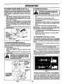
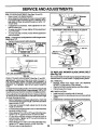
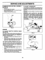
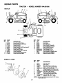
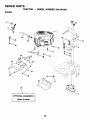
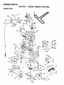
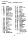
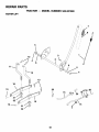
1
SEARS
OWNER'S
MANUAL
MODEL NO.
944.601880
(RRFTSMRWJ
Caution:
Read and follow
all Safety Rules
and
Instructions
Before Operating
Th,s Equipment
20.0 HP
ELECTRIC START
42" MOWER
AUTOMATIC
LAWN TRACTOR
•
•
•
•
•
Assembly
Operation
Customer Responsibilities
Service and Adjustments
Repair Parts
Sears Canada,
Inc., Toronto, Ontario M5B 2B8
Z_
SAFETY RULES
Safe Operation
Practices
for Ride-On
Mowers
Z_
41_
IMPORTANT: THIS CUTTING MACHINE IS CAPABLE OF AMPUTATING HANDS AND FEET ANO THROWING OBJECTS.
FAILURE TO OBSERVE THE FOLLOWING SAFETY INSTRUCTIONS COULD RESULT IN SERIOUS INJURY OR DEATH.
DO NOT:
I. GENERALOPERATION
•
Read, understand, and follow all instructions in the
manual and on the machine before starting.
•
Only allow responsible adults, who are familiar with the
instructions, to operate the machine.
•
Clear the area ofobjects such as recks, toys, wire, etc.,
which could be picked up and thrown by the blade.
•
Be surethe areais clearof other people before mowing.
Stop machine if anyone enters the area.
•
Never carry passengers.
•
Do not mow in reverse unless absolutely necessary.
Always lookdown and behind before and while backing.
•
Be aware of the mower discharge direction and do not
point it at anyone. Do not operate the mower without
either the entire grass catcher or the guard in place.
•
Slowdown beforetuming.
•
Neverleavearunningmachineunattended. Alwaystum
off blades, set parking brake, stop engine, and remove
keys before dismounting.
•
Turn off blades when not mowing.
•
Stop engine before removing grass catcher or unclogging chute.
•
Mow only in daylight or good artificial light.
•
Do notoperate the machine while under the influence of
alcohol or drugs.
•
Watch for traffic when operating near or crossing readways.
•
Use extra care when loading or unloading the machine
into a trailer or truck.
•
Data indicates that operators, age 60 years and above,
are involved in a large percentage of riding mowerrelated injuries. These operators should evaluate their
ability to operate the riding mower safely enough to
protect themselves and others from serious injury.
n. SLOPE OPERATION
Slopes are a rna or factor relatedto loss-of-controland tipover
accidents,whichcan result in severe injuryor death. All slopes
requireextracaution. Ifyoucannotbackup theslopeor ifyoufeel
uneasyon it, do not mow it.
DO:
•
Mow up and down slopes, not across.
•
Remove obstacles such as recks, tree limbs, etc.
•
Watch for holes, ruts, or bumps. Uneven terrain could
overturn the machine. Tafl grass can hide obstacles.
•
Use slow speed. Choose a low gear so that you willnot
have to stop or shift while on the slope.
•
Follow the manufacturer's recommendations for wheel
weights or counterweights to improve stability.
•
Use extra care with grass catchers or other attachments. These can change the stability of the machine.
•
Keep all movementon the slopesslowand gradual. Do not
make suddenchanges in speed or direction.
Avoidstartingor stoppingon a slope. If tires lose traction,
disengagethe bladesand proceedslowlystraightdownthe
slope.
•
Do not turn on slopes unless necessary, and then, turn
slowly and gradually downhill, if possible.
•
Do not mow near drop-offs, ditches, or embankments.
:
The mower couldsuddenlytum over ifawheelis over the
edge of a cliff or ditch, or if an edge caves in.
•
Donotmowonwetgrass.Reducedtractioncouldcause
sliding.
•
Do not try to stabilize the machine by putting your foot
on the ground.
•
Do not use grass catcher on steep slopes.
III. CHILDREN
Tragic accidents can occur if the operator is not alert to the
presence of children. Children are often attracted to the
machine and the mowing activity. Never assume that
children will remain where you last saw them.
•
Keep children out of the mowing area and under the
watchful care of another responsible adult.
•
Be alert and turn machine off if children enter the area.
•
Before and when backing, look behind and down for
small children.
•
Nevercarrychildren. Theymayfalloffandbeseriously
injured or interfere with safe machine operation.
•
Never allow children to operate the machine.
•
Usa extrs care when approaching blindcomers, shrubs,
trees, or other objects that may obscure vision.
IV. SERVICE
•
•
•
•
•
•
•
•
•
•
2
Use extra care in handling gasoline and other fuels.
They are flammable and vapors are explosive.
- Use only an approved container.
- Never remove gas cap or add fuel with the engine
running. Allow engine to coolbefore refueling. Do not
smoke.
- Never refuel the machine indoors.
- Never store the machine or fuel container insidewhere
there is an open flame, such as a water heater.
Never run a machine inside a closed area.
Keep nuts and bolts, especially blade attachment bolts,
tight and keep equipment in good condition.
Never tamper with safety devices. Check their proper
operation regularly.
Keep machine free of grass, leaves, or other dabds
build-up, Clean oilor fuel spillage. Allow machine to coot
before storing.
Stop and inspect the equipment ifyou strike an object.
Repair, if necessary, before restarting.
Never make adjustments or repairs with the engine
running.
Grass catcher components are subject to wear, damage, and deterioration,which couldexpose moving parts
or allowobjects to be threwn. Frequently check components and replace with manufacturer's recommended
parts, when necessary.
Mower blades are sharp and can cut. Wrap the blade(s)
or wear gloves, and use extra caution when servicing
them.
Check brake operation frequently. Adjust and service
as required.
SAFETY RULES
&
Safe Operation
Practices
for Ride-On
Be sure the area is clear of other people before mowing. Stop
machine if anyone enters the area.
Never carry passengers or children even with the blades off.
Do not mow in reverse unless absolutely necessary. Always
look down and behind before and while backing.
Never carry children. They may fall off and be seriously
injured or interfere with safe machine operation.
Keep children out of the mowing area and under the watchful
care of another responsible adult.
Be alert and tum machine off if children enter the area.
Before and when backing, look behind and down for small
children.
Mowers
&
Look for this symbol to point out important
safety precautions.
It means CAUTION]!!
BECOME ALERT!!!
YOUR SAFETY IS INVOLVED.
CAUTION:
Do not coast down a hill in
neutral, you may lose control of the tractor.
Mow up and down slopes (15 ° Max), not across.
Remove obstacles such as rocks, tree limbs, etc.
Watch for holes, ruts, or bumps. Uneven terrain could overturn the machine. Tall grass can hide obstacles.
Use slow speed. Choose a low gear so that you will not have
to stop or shift while on the slope.
&
Avoid starting or stopping on a slope. If tires lose traction,
disengage the blades and proceed slowly straight down the
slope.
If machine stops while going uphill, disengage blades, shift
into reverse and back down slowly.
Do not turn on slopes unless necessary, and then, turn slowly
and gradually downhill, if possible.
CAUTION: Tow only the attachments that
are recommended
by and comply with
specifications of the manufacturer of your
tractor. Use common sense when towing.
Operate only at the lowest possible speed
when on a slope. Too heavy of a load, while
on a slope, is dangerous. TIres can lose
traction with the ground and cause you to
lose control of your tractor.
CAUTION: in order to prevent accidental
starting when setting up, transporting, adjusting or making repairs, always disconnect spark plug wire and place wire where
it cannot contact spark plug.
TABLE OF CONTENTS
SAFETY RULES ...........................................................
2
PRODUCT SPECIFICATIONS .......................................
4
WARRANTY ..................................................................
4
CUSTOMER RESPONSIBILITIES ...................... 4, 15-18
ASSEMBLY ................................................................
6-8
OPERATION .............................................................
9-14
MAINTENANCE SCHEDULE .......................................
15
SERVICE AND ADJUSTMENTS ............................. 19-23
STORAGE ...................................................................
24
TROUBLESHOOTING .............................................
25-26
REPAIR PARTS - TRACTOR .................................. 28-45
REPAIR PARTS - ENGINE ...................................... 46-50
PARTS ORDERING/SERVICE ................. BACK COVER
3
PRODUCT
MAINTENANCE
SPECIFICATIONS
GASOLINE CAPACITY
AND TYPE:
A Sears Maintenance Agreement is available on this preduct. Contact your nearest Sears store for details.
3.5 GALLONS
UNLEADED REGULAR
OIL TYPE (API-SF-SJ):
SAE 30 (above 32°F)
SAE 5W-30 (below 32°F)
SYNTHETIC (below 0°F)
Your tractorwas shippedfrornthe factorywith non-syntheticSAE
=10W-30 motoro .
OIL CAPACITY:
4 PINTS
SPARK PLUG:
(GAP: .030")
CHAMPION
VALVE CLEARANCE:
INTAKE:
EXHAUST:
.004" - .006"
.004" - .006"
GROUND SPEED (MPH):
FORWARD:
REVERSE:
5.5
2.4
TIRE PRESSURE:
FRONT:
REAR:
14 PSI
10 PSI
CHARGING SYSTEM:
3 AMPS BATTERY
5 AMPS HEADLIGHTS
BATTERY:
AMP/HR:
MIN. CCA:
CASE SIZE:
BLADE BOLT TORQUE:
27-35 FT. LBS.
I
AGREEMENT
CUSTOMER
•
•
•
RC12YC
RESPONSIBILITIES
Read and observe the safety rules.
Follow a regular schedule in maintaining, cadng for and
using your tractor.
Follow the instructions under "Customer
Responsibilities" and "Storage" sections of this owner's manual.
WARNING: This tractor is equipped with an internal combustion engine and should not be used on or near any
unimproved forest-covered, brush-covered or grass-covered land unless the engine's exhaust system is equipped
with a spark arrester meeting applicable local or state laws
(if any). If a spark arrester is used, it should be maintained
in effective working order by the operator.
A spark arrester for the muffler is available through your
nearest Sears Authorized Service Centre/Department (See
REPAIR PARTS section of this manual),
30
240
UIR
CONGRATULATIONS
on your purchase ofa Sears Tractor. It has been designed, engineered and manufactured to give you
the best possible dependability and performance.
Should you experience any problem you cannot easily remedy, please contact your nearest Sears Authorized Service Centre/
Department. We have competent, well-trained technicians and the proper tools to service or repair this tractor.
Please read and retain this manual. The instructionswill enable you to assemble and maintain your tractor properly. Always
observe the =SAFETY RULES".
WARRANTY
LIMITED
TWO (2) YEAR WARRANTY
ON CRAFTSMAN
TRACTOR
(RIDING
EQUIPMENT)
For two (2) years from date of purchase Sears Canada, Inc. will repair or replace at Sears option free of charge pads which
are defective as a result of matedal or workmanship.
FULL ONE (1) YEAR WARRANTY ON BATTERY
For one (1) year from date of purchase, if any battery included with this dding equipment proves defective in material or
workmanship and our testing determines the battery will not hold a charge, Sears will replace the battery at no charge.
COMMERCIAL OR RENTAL USE
Warranty on Riding Equipment used for commercial or rental purposes is limited to ninety (90) days.
This Warranty does _
cover:
1.
2.
3.
4.
Pre-delivery set-up.
Tire replacement or repair caused by punctures from outside objects (such as nails, thoms, stumps, or glass).
Expendable items which become worn during normal use, such as blades, spark plug, air cleaners and belts.
Repairs necessary because of operator abuse or negligence, including damaged jackshaft or mandrel and the
failure to operate and maintain the equipment according to the instructions contained in the Owner's Manual.
5. In Home service.
Warranty service is available by returning the Craftsman Riding Equipment to the nearest Sears Service Centre/Depadment in
Canada. This warranty applies only while this product is in use in Canada.
This warranty is in addition to any statutory warranty and does not exclude or limit legal rights you may have but shall run
concurrently with applicable provincial legislation. Furthermore, some provinces do NOT allow limitation on how long an
implied warranty will last so the above limitations may not apply to you.
SEARS CANADA, INC., TORONTO, ONTARIO M5B 2B8
4
UNASSEMBLED PARTS
Steering
Wheel
Seat
Wheel
Steering
,
_
, Adapter
(1) Washer
17/32 x 1-3/16 x 12 Gauge
Extension
Shaft
t
Steedng
(1) Knob
Steering
Wheel
O Insert
Baffery
Boot
(1) Lockwasher 3/8
(1) Locknut
5/16-18
(2) Hex Bolts 1/4-20 x 3/4
(2) Keps Nuts 1/4-20
(1) Large Flat
Washer
Keys
(1) Hex Bolt
3/8-16 x 1
Slope Sheet
(2) Keys
(1) Oil Drain Tube
5/16-18 x 1-1/4
(1) Hex Bolt
5
ASSEMBLY
Your new tractor has been assembled at the factory with exception of those parts left unassembled for shipping purposes. To
ensure safe and proper operation of your tractor all parts and hardware you assemble must be tightened securely. Use the
correct tools as necessary to insure proper tightness.
TOOLS
REQUIRED
FOR ASSEMBLY
A socket wrench set will make assembly easier. Standard
wrench sizes are listed.
(1) 9/16" wrench
(2) 7/16" wrenches
(2) 1/2" wrenches
Pliers
Tire pressure gauge
Utility knife
When rightor lefthand is mentioned in this manual, it means
when you are in the operating position (seated behind the
steering wheel).
WHEEL
TO REMOVE TRACTOR FROM CARTON
STEERING
UNPACK
CARTON
•
Remove all accessible loose parts and parts cartons
from carton.
•
Cut, from top to bottom, along lines on all four comers
of carton, and lay panels flat.
•
Check for any additional loose parts or cartons and
remove.
BOOT
d_TABS
ADAPTER.---""
_'_
EXTENSION
BEFORE REMOVING TRACTOR FROM
SKID
ATrACH
STEERING
WHEEL
SHAFT
5/16 HEX BOLT
(See Fig. 1)
ASSEMBLE EXTENSION SHAFT AND BOOT
•
Slide extension shaft onto lower steering shaft. Align
mounting holes in extension and Iowershafts and install
5/16 hex bolt and Iocknut. Tighten securely.
•
Place tabs of steering boot over tab slots in dash and
push down to secure.
I
I
I
I
I
SLOTS
INSTALLSTEERING WHEEL
•
Position front wheels of the tractor so they are pointing
straight forward.
•
Remove steeringwheel adapter from steering wheel and
slide adapter onto steering shaft extension.
•
Position steedng wheel so cross bars are horizontal (left
to right) and slide inside boot and onto adapter.
•
Assemble large flat washer, 3/8 lock washer, 3/8 hex
bolt and tighten securely.
•
Snap steering wheel insertintocenter of steering wheel.
•
Remove protective rnaterials from tractorhood and grill.
IMPORTANT: CHECK FOR AND REMOVE ANY STAPLES
IN SKID THAT MAY PUNCTU RE TIRES WHERE TRACTOR
IS TO ROLL OFF SKID.
FIG. 1
HOW TO SET UP YOUR TRACTOR
CONNECT
_b
BATTERY
(See Fig. 2)
CAUTION: Do not short battery terminals by allowing a wrench or any other
object to contact both terminals at the
sametime. Before connecting battery,
remove metal bracelets, wristwatch
bands, rings, etc.
Positive terminal must be connected
first to prevent sparking from accidental
grounding.
6
ASSEMBLY
•
•
Uft hood to raised position.
Open terminal access doors, remove terminal protective caps and discard.
•
If this battery is put into service after month and year
indicated on label (label located between terminals)
charge battery for minimum of one hour at 6-10 amps.
•
First connect RED battery cable to positive (+) battery
terminal with hex bolt and keps nut as shown. Tighten
securely.
•
Connect BLACK groundingcable to negative (-) battery
terminal with remaining hex bolt and keps nut. Tighten
securely.
•
Close terminal access doors.
Use terminal access doors for:
•
Inspection for secure connections (to tighten har
_ jSEAT
i -_ "_-.._ _'..
%
-_
FLAT WASHER
,o..
KNOB
dware).
•
•
•
•
"" __
._'_
SHOULDER
BOLT
_=_
_'_ _
FIG. 3
Inspection for corrosion.
Testing battery.
Jumping (ifrequired).
Pedodiccharging.
DISCARD
TERMINAL
PROTECTIVE
CAPS
_
_
NOTE: You may now roll or drive your tractor off the sldd.
Follow the appropriata instruction below to remove the
tractor from the skid.
TO ROLL TRACTOR
section for location
KEPS
HEX BOLT
OFF SKID (See Operation
and function
of controls)
•
Press lift lever plunger and raise attachment lift lever to
its highest position.
•
Release parkingbrake by depressingclutch/brake pedal.
•
Place freewheel control in freewheeling position to
disengage transmission (See "TO TRANSPORT" in the
Operation section of this manual).
Roll tractor forward off skid.
POSITIVE
Remove banding holding discharge guard up against
tractor.
(RF.D)CABUE
TO DRIVE TRACTOR
OFF SKID (See Operation section for location and function of con-
NEGATIVE
(BLACK)CABLE
trols)
• kWARNING: Before starting, read, understand and follow
all instructions in the Operation section of this manual. Be
sure tractor is in a well-ventilated area. Be sure the area in
front of tractor is clear of other people and objects.
•
Be sure all the above assembly steps have been
completed.
•
Check engine oil level and fillfuel tank with gasoline.
•
Place freewheel control in "transmissionengaged" position.
FIG. 2
INSTALL SEAT (See Fig. 3)
Adjust seat before tightening adjustment knob.
•
Remove adjustment knoband flat washer securing seat
to cardboard packing and set aside for assembly of seat
to tractor.
•
•
•
•
•
•
•
•
Pivot seat upward and remove from the cardboard
packing. Remove the cardboard packing and discard.
Place seat on seat pan so head of shoulder bolt is
positioned over large slotted hole in pan.
Push down on seat to engage shoulder bolt in slot and
pull seat towards rear of tractor.
Pivot seat and pan forward and assemble adjustment
knob and fiat washer loosely, Do not tighten.
Lower seat into operating position and sit on seat.
Slide seat untila comfortable position is reached which
allows you to press clutch/brake pedal all the way down.
Get off seat without moving its adjusted position.
Raise seat and tighten adjustment knob securely.
•
7
Sit on seat in operating position, depress clutch/brake
pedal and set the parking brake.
•
Place motion control lever in neutral (N) position.
•
Press lift lever plunger and raise attachment liftlever to
its highest position.
•
Startthe engine. Afterengine has started, move throttle
control to idle position.
•
Release parking brake.
•
Slowly move the motion controllever forward and slowly
ddve tractor off skid.
•
Apply breke to stop tractor, set parking brake and place
motion control lever in neutral position.
•
Turn ignition key to 'OFF" position.
Continue with the instructionsthat follow.
ASSEMBLY
INSTALL
MULCHER
CHECK
BELTS
PLATE
(If previously removed) (See Rg. 4)
•
Raise and hold deflector shield in updght position.
•
Place front of mulcher plate over front of mower deck
opening and slide into place, as shown.
•
Hook front latch into hole on front of mower deck.
•
Hook rear latch into hole on back of mower deck.
A
FOR
PROPER
POSITION
OF ALL
See the figures that are shown for replacing motion and
mower blade drive belts in the Service and Adjustments
section of this manual. Verify that the belts are routed
correctly.
CHECK BRAKE SYSTEM
After you leam how to operate your tractor, check to see that
the brake is propedy adjusted. See "TO ADJUST BRAKE"
in the Service and Adjustments section of this manual.
shield from mower. Raise and hold shield
CAUTION:
Do mulcher
not remove
deflector
when attaching
plate and
allow
it to rest on plate while in operation.
,/'CHECKLIST
DEFLECTOR
SHIELD
BEFORE YOU OPERA TE AND ENJO Y YOUR NEW TRACTOR, WE WISH TO ASSURE THAT YOU RECEIVE THE
BEST PERFORMANCE AND SATISFACTION FROM THIS
QUALITY PRODUCT.
MULCHER
PLATE
PLEASE REVIEW THE FOLLOWING CHECKLIST:
/
All assembly instructions have been completed.
J
No remaining loose parts in carton.
,/
Battery is properly prepared and charged. (Minimum 1
hour at 6 amps).
,/ Seat is adjusted comfortably and tightened securely.
/
All tires are properly inflated. (For shipping purposes,
the tires were ovednflated at the factory).
,/ Be sure mower deck is propedy leveled side-to-side/
front-to-rear for best cutting results. (TIres must be
propedy inflated for leveling).
/
Check mower and drive belts. Be sure they are reuted
propedy around pulleys and inside all belt keepers.
,/
Check wiring. See that all connections are still secure
and wires are propedy clamped.
J
Before driving tractor, be sure freewheel control is in
drive position.
LATCH
HOOKS
FIG. 4
TO CONVERT TO BAGGING OR
DISCHARGING
Simply remove mulcher plate and store in a safe place. You r
mower is now ready for discharging or installationofoptional
grass c_tcher accessory.
NOTE: It is not necessary to change blades. The mulcher
blades are designed for discharging and bagging also.
WHILE LEARNING HOW TO USE YOUR TRACTOR, PAY
EXTRA ATTENTION TO THE FOLLOWING IMPORTANT
ITEMS:
CHECK TIRE PRESSURE
The tires on your tractor were ovednflated at the factory for
shipping purposes. Correct tire pressure is important for
best cutting performance.
•
Reduce tire pressure to PSI shown in _PRODUCT
SPECIFICATIONS" section of this manual.
/
,/
•/
CHECK DECK LEVELNESS
/
/
For best cutting results, mower housing should be propedy
leveled. See'q'O LEVEL MOWER HOUSING" in the Service
and Adjustments section of this manual.
8
Engine oil is at proper level
Fuel tank is filled with fresh, clean, regular unleaded
gasoline.
Become familiar with all controls - their location and
function. Operate them before you start the engine.
Be sure brake system is in sate operating condition,
It isimportanttopurge the transmission before operating
your tractor for the first time. Follow proper starting and
transmission purging instructions (See "TO START
ENGINE" and "PURGE TRANSMISSION" in the Operation section of this manual).
OPERATION
These symbols may appear on your tractor or in literature supplied with the product. Learn and understand their meaning.
BA'I-rERY
CAUTION OR
WARNING
REVERSE
FORWARD
FAST
SLOW
ENG,NEON
ENG,NEOFF
O,LPRESSORE
L.G.TSON
0%T_.P
FUEL
r 'l
A'I-rACHMENT
CLUTCH ENGAGED
IGNITION
CHOKE
MOWER HEIGHT
PARKING BRAKE
LOCKED
UNLOCKED
MOWER LIFT
R N H
REVERSE
NEUTRAL
ATTACHMENT
CLUTCH DISENGAGED
HIGH
LOW
KEEP AREA CLEAR
PARKING BRAKE
SLOPE HAZARDS
(SEE SAFETY RULES SECTION)
FREE WHEEL
(Automatic Models only)
DANGER, KEEP HANDS AND FEET AWAY
9
OPERATION
KNOW YOUR TRACTOR
READ THIS OWNER'S
MANUAL
AND SAFETY
RULES
Compare theillustrationswith your tractor to familiarizeyourself
this manual for future reference,
BEFORE
OPERATING
YOUR TRACTOR
with the locations of various controls and adjustments. Save
ATTACHMENT
CLUTCH LEVER
IGNITION
SWITCH
LIGHT
POSITION
AMMETER
CHOKE
CONTROL
LIFT LEVER
PLUNGER
THROTTLE
CONTROL
ATTACHMENT
UFT LEVER
CLUTCH/
BRAKE
PEDAL
MOWER DECK
HEIGHT
ADJUSTMENT
POSITIONS
PARKING
BRAKE
FREE WHEEL
CONTROL
CONTROL
LEVER
FIG. 5
Our tractors conform to the safety standards of the Amedcan National Standards Institute.
ATFACHMENT CLUTCH LEVER: Used to engage the
mower bledes, or other attechments mounted toyour tractor.
LIGHT SWITCH: Tums the headlights on and off.
AMMETER:
Indicates charging (+) or discharging (-) of
battery.
MOTION CONTROL LEVER:
Selects the speed and
direction of tractor.
THROTTLE CONTROL: Used to control engine speed.
CHOKE CONTROL: Used when starting a cold engine.
ATTACHMENT LIFT LEVER: Used to raise, lower, and
adjust the mower deck or other attachments mounted toyour
tractor.
UFT LEVER PLUNGER: Used to release attachment lift
lever when changing its position.
IGNITION SWITCH: Used for starting and stopping the
engine.
CLUTCH/BRAKE PEDAL: Used for declutching and braking the tractor and starting the engine.
PARKING BRAKE: Locks clutch/brake pedal intothe brake
position.
FREEWHEEL CONTROL: Disengages transmission for
pushing or slowly towing the tractor with the engine off.
10
OPERATION
I _1__
r
•
_
GI.ASSr=S
I
JL.
•
The operation of any tractor can result in foreign objects thrown into the eyes, which can
I
result in severe eye damage. Always wear safety glasses or eye shields while operating
your tractor or performing any adjustments or repairs. We recommend a wide vision
I
|
safety mask over spectacles or standard safety glasses.
HOW TO USE YOUR TRACTOR
TO SET PARKING BRAKE (See Fig. 6)
Your tractor isequipped with an operator presence sensing
switch. When engine is running, any attempt by the operator
to leave the seat without first setting the parking brake will
shut off the engine.
•
Depress clutch/brake pedal into full "BRAKE" position
and hold.
•
Place parking brake lever in "ENGAGED" position and
release pressure from clutch/brake pedal. Pedalshould
remain in "BRAKE" position. Make sure parking brake
will hold tractor secure.
ATTACHMENT
CLUTCH
LEVER "ENGAGED"
POSITION
CHOKE
CONTROL
IGNITION
KEY
IMPORTANT: LEAVING THE IGNITION SWITCH IN ANY
POSITION OTHER THAN "OFF" WILL CAUSE THE
BATTERY TO BE DISCHARGED, (DEAD).
NOTE: Under certainconditionswhen tractorisstandingidle
with the engine running, hot engine exhaust gases may
cause '10rowning"of grass. To eliminate this possibility,
always stop engine when stopping tractor on grass areas.
pletely, as described above, before leaving the operator's position; to empty
CAUTION: Always stop tractor comgrass catcher, etc.
TO USE
THRO'n'LE
CONTROL
I
(See Fig. 6)
Always operate engine at full throttle.
•
Operating engine at less than full throttle reduces the
battery charging rate.
•
Full throttle offers the best bagging and mower performance.
TO USE CHOKE CONTROL (See Fig. 6)
CONTROL
Use choke control whenever you are starting a cold engine.
Do not use to start a warm engine.
•
To engage choke control, pull knob out. Slowly push
knob in to disengage.
"BRAKE"
POSITION
TO MOVE FORWARD AND BACKWARD (See
Fig. 6)
CONTROL
LEVER
CLUTCH/BRAKE
PEDAL
"DRIVE" PosmoN
PARKING BRAKE
"DISENGAGED"
POSITION
FIG. 6
STOPPING
(See Fig. 6)
MOWER BLADES•
To stop mower blades,move attachment clutch lever to
"DISENGAGED" position.
GROUND DRIVE•
To stop ground drive, depress clutch/brake pedal into
full "BRAKE" position.
•
Move motion control lever to neutral (N) position.
IMPORTANT:
THE MOTION CONTROL LEVER DOES
NOT RETURN TO NEUTRAL (N) POSITION WHEN THE
CLUTCH/BRAKE PEDAL IS DEPRESSED.
ENGINE•
Move throttle control to slow position.
The direction and speed of movement is controlled by the
motion control lever.
•
•
•
Start tractor with motion control lever in neutral (N)
position.
Release parking brake and clutch/brake pedal.
Slowly move motion control lever to desired position.
TO ADJUST
(See Fig. 6)
MOWER
cu'n'ING
HEIGHT
The position of the attachment lift lever determines the
cuffing height.
•
Grasp lift lever.
•
Press plunger with thumb and move lever to desired
position.
The cuffing height range is approximately 1- 1/2 to 4". The
heights are measured from the ground to the blade tip with
the engine not running. These heights are approximate and
may vary depending upon soil conditions, height of grass
and types of grass being mowed.
NOTE: Failure to move throttle control to slow position and
•
The average lawn should be cutto approximately 2-1/2
allowing engine to idle before stopping may cause engine to
inches during the cool season and to over 3 inches
'1oackfire".
during hot months. For healthier and better looking
•
Tum ignition key to "OFF" position and remove key.
lawns, mow often and after moderate growth.
Always remove key when leaving tractor to prevent
•
For best cutting performance, grass over 6 inches in
unauthorized use.
height should be mowed twice. Make the first cut
11
•
Never use choke to stop engine.
relatively high; the second to desired height.
OPERATION
TO ADJUST
GAUGE
(See
WHEELS
TO OPERATE
Fig. 7)
Gauge wheels are properly adjusted when they are slightly
off the ground when mower is at the desired cutting height in
operating position. Gauge wheels then keep the deck in
proper position to help prevent scalping in most terrain
conditions.
•
Adjust gauge wheels with tractor on a flat level surface.
•
Adjust mower to desired cutting height (See "TO ADJUST MOWER CUq-I'ING HEIGHT" in the Operation
section of this manual).
•
With mower in desired height of cut position, gauge
wheels should be assembled so they are slightly offthe
ground. Install gauge wheel in appropriate hole with
shoulder bolt, 3/8 washer, and 3/8-16 Iocknut and tighten
securely.
•
Repeat for opposite side installing gauge wheel insame
adjustment hole.
with slopes greater than 15 ° and do not
CAUTION:
notslope.
drive up or down hills
drive
acrossDoany
Choose the slowest speed before starting up or down
hills.
•
•
Avoid stopping or changing speed on hills.
If slowing is necessary, move throttle control lever to
slower position.
If stopping is absolutely necessary, push clutch/brake
pedal quickly to brake position and engage parking
brake.
•
•
Move motion control lever to neutral (N) position.
IMPORTANT:
THE MOTION CONTROL LEVER DOES
NOT RETURN TO NEUTRAL (N) POSITION WHEN THE
CLUTCH/BRAKE PEDAL IS DEPRESSED.
3/8-16
•
•
GUAGE WHEEL
MOUNTING
SHOULDER
BOLT
TO OPERATE
MOWER
(See Fig. 8)
Your tractor isequipped with an operator presence sensing
switch. Any attempt by the operator to leave the seat with
the engine running and the attachment clutch engaged will
shut off the engine.
•
Select desired height of cut.
•
Start mower blades by engaging attachment clutch
control.
•
TO STOP MOWER BLADES - disengage attachment
clutch control.
"ENGAGED"
(See
Figs.
5 and 9)
When pushing or towing your tractor, be sure to disengage
transmission by placing freewheel control in freewheeling
position. Free wheel controlis located at the rear drawbar of
tractor.
FIG. 7
I_IL
To restart movement, slowly release parking brake and
clutch/brake pedal.
Slowly move motion control lever to slowest setting.
Make all turns slowly.
TO TRANSPORT
WHEEl,:
wlthout either the enUre grass catcher,
on
mowers Do
so not
equipped,
disCAUTION:
operate or
thethe
mower
charge guard in place.
I
•
•
3/8 WASHF-I =
GAUGE
ON HILLS
•
•
•
•
Raise attachment lift to highest position with attachment lift control.
Pull freewheel control out and down into the slot and
release so it is held in the disengaged position.
Do not push or tow tractor at more than two (2) MPH.
To reengage transmission, reverse above procedure.
NOTE: To protect hood from damage when transporting
your tractor on a truck or a trailer, be sure hood isclosed and
secured to tractor. Use an appropriate means of tying hood
to tractor (rope, cord, etc.).
I
I
POSITION
ATTACHMENT
HIGH POSI-
/:/ TION
./._//
LOW
POSITION
DISCHARGE
GUARD
FIG. 9
TOWING CARTS AND OTHER ATTACHMENTS
CLUTCH LEVER
"DISENGAGED"
Tow only the attachments that are recommended by and
comply with specifications of the manufacturer of your
tractor. Use common sense when towing. Too heavy of a
load, while on a slope, is dangerous. Tires can lose traction
with the ground and cause you to lose control ofyour tractor.
POSITION
FIG. 8
12
OPERATION
BEFORE
STARTING
•
THE ENGINE
CHECK
ENGINE
OIL LEVEL (See Fig. 14)
•
The engine in your tractor has been shipped, from the
factory, already filled with summer weight oil.
•
Check engine oil with tractor on level ground.
•
Remove oil fillcap/dipstick and wipe clean, reinsert the
dipstick and screw cap tight, wait for a few seconds,
remove and read oil level. If necessaP/, add oil until
"FULL" mark on dipstick is reached. Do not overfill.
•
For cold weather operation you should change oil for
easier starting (See =OIL VISCOSITY CHART" in the
Customer Responsibilities section of this manual).
•
Tochange engine oil, seethe Customer Responsibilities
section in this manual.
WARM WEATHER STARTING (50 ° F and above)
•
When engine starts, slowly push choke control in until
the engine begins to run smoothly. If the engine starts
to run roughly,pullthe choke controlout slightlyfor a few
seconds and then continue topush the controlin slowly.
•
The attachments and ground drive can now be used. If
the engine does not accept the load, restart the engine
and allow itto warm up for one minute using the choke
as described above.
COLD WEATHER STARTING (50 ° F and below)
•
When engine starts, slowly push choke control in until
the engine begins to run smoothly. Continue to push the
choke control in small steps allowing the engine to
accept small changes in speed and load, untilthe choke
control is fullyin. Ifthe engine starts to run roughly, pull
the choke controlout slightlyfor a few seconds and then
continue to pushthe control in slowly. This may require
an engine warm-up period from several seconds to
several minutes, depending on the temperature.
AUTOMATIC TRANSMISSION WARM UP
•
Before ddvingthe unit in coldweather, the transmission
should be warmed up as follows:
•
Be sure the tractor is on level ground.
•
Place the motion control lever in neutral. Release
the parking brake and let the clutch/brake
slowly return to operating position.
• Allow one minute for transmission to warm up. This
can be done during the engine warm up pedod.
•
The attachments can be used during the engine warmup period after the transmission has been warmed up
and may require the choke control be pulled out slightly.
NOTE: If at a high altitude (above 3000 feet) or in cold
temperatures (below 32 F) the carburetor fuel mixture may
need to be adjusted for best engine performance. See "TO
ADJUST CARBURETOR" in the Service and Adjustments
section of this manual.
ADD GASOLINE
•
Fill fuel tank. Use fresh, clean, regular unleaded
gasoline with a minimum of 87 octane. (Use of leaded
gasoline will increase carbon and lead oxide deposits
and reduce valve life). Do not mix oil with gasoline.
Purchase fuel in quantities that can be used within 30
days to assure fuel freshness.
IMPORTANT: WHEN OPERATING IN TEMPERATURES
BELOW 32°F(0°C), USE FRESH, CLEAN WINTER GRADE
GASOLINE TO HELP INSURE GOOD COLD WEATHER
STARTING.
WARNING: Experience indicates that alcoholblended fuels
(called gasohol or using ethanol or methanol) can attract
moisture which leads to separation and formation of acids
during storage. Acidic gas can damage the fuel system of
an engine while in storage. To avoid engine problems, the
fuel system should be emptied before storage of 30 days or
longer. Drain the gastank, start the engine and let it rununtil
the fuel lines and carburetor are empty. Use fresh fuel next
season. See Storage Instructionsfor additional information.
Never use engine or carburetor cleaner products in the fuel
tank or permanent damage may occur.
I_IL
filler neck. Do not overfill. Wipe offany
spilled oil or fuel. Do not store, spill or
AUTION:
to an
bottom
gas tank
use
gasoline Fill
near
open of
flame.
Insert key into ignition and tum key clockwise to
"START" position and release key as soon as engine
starts. Do not run starter continuously for more than
fifteen seconds per minute, if the engine does not start
after several attempts, push choke controlin, wait a few
minutes and try again. If engine still does not start, pull
the choke control out and retry.
I
I
PURGE TRANSMISSION
TO START ENGINE (See Fig, 5)
When starting the engine forthe firsttime or ifthe engine has
run out of fuel, it will take extra cranking time to move fuel
from the tank to the engine.
•
Be sure freewheelcontml isinthetransmission engaged
position.
•
Sit on seat in operating position, depress clutch/brake
pedal and set parking brake.
•
Place motion control lever in neutral (N) position.
•
Move attachment clutch to =DISENGAGED" position.
•
Move throttle control to fast position
•
Pullchoke control out for acold engine start attempt. For
a warm engine start attempt the choke control may not
be needed.
I_k
NOTE: Before starting, read the warm and cold starting
procedures below.
13
freewheel lever while the engine is runAUTION: Neverengageordisengage
ning.
J
To ensure proper operation and performance, it is recommended that the transmission be purged before operating
tractor for the first time. This procedure will remove any
trapped air inside the transmission which may have developed during shipping of your tractor.
IMPORTANT: SHOULDYOURTRANSMISSION REQUIRE
REMOVAL FOR SERVICE OR REPLACEMENT,
IT
SHOULD BE PURGED AFTER REINSTALLATION BEFORE
OPERATING THE TRACTOR.
•
Place tractor safely on level surface with engine off and
parking brake set.
•
Disengage transmission by placingfreewheel controlin
freewheeling position (See -TO TRANSPORT" in this
section of manual).
OPERATION
•
Sifting in the tractor seat, start engine. After the engine
is running, move throttle control to slow position. With
motion control lever in neutral (N) position, slowly
disengage clutch/brake pedal.
Move motion control lever to full forward position and
hold for five (5) seconds. Move lever to full reverse
position and hold for five (5) seconds. Repeat this
procedure three (3) times.
•
t
NOTE: During this procedure there will be no movement of
drive wheels. The air is being removed from hydraulic drive
system.
•
Move motion control lever to neutral (N) position. Shutoff engine and set parking brake.
•
Engage transmission by placing freewheel control in
driving position (See "TO TRANSPORT" in this section
of manual).
•
Sitting in the tractor seat, start engine. After the engine
is running, move throttle controlto half ( 1/2) speed. With
motion control lever in neutral (N) position, slowly
disengage clutch/brake pedal.
•
Slowly move motion control lever forward, after the
tractor moves approximately five (5) feet, slowly move
motion control lever to reverse position.After the tractor
moves approximately five (5) feet return the motion
control lever to the neutral (N) position. Repeat this
procedure with the motion control leverthree (3) times.
•
Your tractor is now purged and now ready for normal
operation.
J
FIG. 10
MULCHING
•
•
•
•
•
•
•
TIPS
IMPORTANT: FOR BEST PERFORMANCE, KEEP MOWER
HOUSING FREE OF BUILT-UP GRASS AND TRASH.
CLEAN AFTER EACH USE.
•
The special mulching blade willrecutthe grass clippings
many times and reduce them in size so that as they fall
ontothe lawn they will disperse intothe grass and not be
noticed. Also, the mulched grass will biodegrade
quickly to provide nutrients for the lawn. Always mulch
with your highest engine (blade) speed as this will
provide the best recutting action of the blades.
•
Avoid cutting your lawn when it iswet. Wet grass tends
to form clumps and interferes with the mulching action.
The best time to mow your lawn is the early afternoon.
At this time the grass has dried and the newly cut area
will not be exposed to the direct sun.
•
For best results, adjust the mower cutting height so that
the mower cuts off only the top one-third of the grass
blades (See Fig. 11). For extremely heavy mulching,
reduce your width of cut on each pass and mow slowly.
•
Certain types of grass and grass conditionsmay require
that an area be mulched a second time to completely
hide the clippings. When doing a second cut, mow
across or perpendicular to the first cut path.
•
Change your cutting pattern from week to week. Mow
north to southone week then change to east to west the
next week. This will help prevent matting and graining
of the lawn.
MOWING TIPS
•
MOWING
Mower should be properly leveled for best mowing
performance. See "TO LEVEL MOWER HOUSING" in
the Service and Adjustments section of this manual.
The lefthand side of mower shouldbe used for trimming.
Drive so that clippings are discharged ontothe areathat
has been cut. Have the cut area to the right of the
machine. This will result in a more even distribution of
clippings and more uniform cutting.
When mowinglarge areas, start bytumingtothe dght so
that clippings will discharge away from shrubs, fences,
driveways, etc. After one or two rounds, mow in the
opposite direction making left hand tums until finished
(See Fig. 10).
If grass is extremely tall, it should be mowed twice to
reduce load and possible fire hazard from dried clippings. Make first cut relatively high; the second to the
desired height.
Do not mow grass when it is wet. Wet grass will plug
mower and leave undesirableclumps. Allowgrass todry
before mowing.
Always operate engine at full throttle when mowing
to assure better mowing performance and proper discharge ofmaterial. Regulate ground speed by selecting
a low enough gear to give the mower cutting performance as well as the quality of cut desired.
When operating attachments, select a ground speed
that willsuit the terrain and give best performance ofthe
attachment being used.
MAX 1_
FIG. 11
14
CUSTOMER RESPONSIBILITIES
.A,NTENANCE
SC.EOU'E
"
AS YOU COMPLETE
REGUlaR
SERV,CE
Yf
Check Tire
BrakePressure
Operation
Check
Check Operator
T
, SERV'CE
......
DATES
_
Presence
and
Interlock
Check forSystems
Loose Fasteners
11_7
Lubrication Chart
T
A
R
Check
Battery Level
SharperVReplace
Mower Blades
Clean Battery and Terminals
_4
Check Transaxle
V'
V'5
Adjust Motion Drive Belt(s) Tension
I_'s
Engine Oil Level
Change
N
Cooling
Adjust Blade Belt(s) Tension
Check
E
V'
Clean
Engine
_
I1_
Oil
Air Filter
11_2
J Clean Air Screen
G
Inspect Muffler/Spark
NI
Replace
E
Clean Engine Cooling
V =
_1,2,3
I
_2
An'ester
Ii_
Oil Filter (If equipped)
_1,2
V=2
Fins
Replace Spark Plug
Replace Air Filter Paper Cartridge
Replace
12 3 4 -
_/_2
Fuel Filter
V #
Change more often when operating under a heavy load or in high ambient temperatures,
Service more often when operating in dirty or dusty conditions.
if equipped with oil fl_er, change oil every 50 hours,
Replace b_ades more often when mowing in sandy soil.
5 - If equipped wi_ adjustable system.
6 - Not requ_rad if equipped with maintenance-free baser/,
7 - "llghten front axle pivot bolt to 35 fL-Ibs, maximum,
Do not overtlghten.
LUBRICATION
GENERAL
CHART
RECOMMENDATIONS
ZERK
The warranty on this tractor does not cover items that have
been subjected tooperator abuse or negligence. To receive
fullvalue from the warranty, operator must maintain tractor
as instructed in this manual.
(1)FRONT
BEARING
ZERK
ZERK
"(_)FRONTWHEEL
BEARING ZERK
Some adjustments will need to be made periodically to
properly maintain your tractor.
All adjustments in the Service and Adjustments section of
this manual should be checked at least once each season.
•
Once a yearyou should replace the spark plug, clean or
replace air filter, and check blades and belts for wear. A
new spark plugand clean air filter assure proper air-fuel
mixtureand help your engine run better and last longer.
BEFORE
•
•
•
•
•
EACH
USE
Check engine oil level.
Check brakeoperation.
Check tire pressure,
Check operator presence and
interlock systems for proper operation.
Check for loose fasteners.
L'DGENERAL PURPOSE GREASE
_)REFER TO CUSTOMER RESPONSIBILITIES
SECTION
15
"ENGINE"
IMPORTANT:
DO NOT OIL OR GREASE THE PIVOT POINTS
WHICH HAVE SPECIAL NYLON BEARINGS.
VISCOUS LUBRICANTS WILL ATTRACT DUST AND DIRT THAT WILL SHORTEN
THE LIFE OF THE SELF-LUBRICATING
BEARINGS.
IF YOU
FEEL THEY MUST BE LUBRICATED,
USE ONLY A DRY, POWDERED GRAPHITE
TYPE LUBRICANT
SPARINGLY.
CUSTOMER
RESPONSIBILITIES
TRACTOR
TRA|LtNG
"uP
Always observe safety rules when performing any maintenance.
BRAKE
BLADE
CENTER
HOLE
OPERATION
If tractor requiras more than six (6) feet stopping distance at
high speed in highest gear, then brake must be adjusted.
(See "TO ADJUST BRAKE" in the Service and Adjustrnents
section of this manual).
LOCK WASHER
•
•
f
Maintain proper air pressure in alltires (See"PRODUCT
SPECIFICATIONS" section of this manual).
Keep tires free of gasoline, oil, or insect control chemicals which can harm rubber.
Avoid stumps, stones, deep ruts, sharp objects and
other hazards that may cause tire damage.
FLAT WASHER
HEX BOLT (GRADE 8)*
*A GRADE 8 HEAT TREATED BOLT CAN BE
IDENTIFIED BY SIX LINES ON THE BOLT HEAD.
FIG. 12
TO SHARPEN
NOTE: To seal tire punctures and prevent flat tires due to
slow leaks, tire sealant may be purchased from your local
parts dealer. Tire sealant also prevents tire dry rot and
corrosion.
OPERATOR
PRESENCE
BLADE
(See
Fig. 13)
NOTE: We do not recommend sharpening blade - but ifyou
do, be sure the blade is balanced.
Care should be taken to keep the blade balanced. An
unbalanced blade will cause excessive vibration and eventual damage to mower and engine.
•
The blade can be sharpened with a file or on a grinding
wheel. Do not attempt to sharpen while on the mower.
•
To check blade balance, you will need a 5/8" diameter
steel bolt, pin, or a cone balancer. (When using a cone
balancer, follow the Instructions supplied with balancer).
SYSTEM
Be sure operator presence and interlock systems are working properly. If your tractor does not function as described,
repair the problem immediately.
•
The engine should not start unless the clutch/brake
pedal isfully depressed and attachement clutch control
is in the disengaged position.
•
When the engine is running, any attempt bythe operator
to leave the seat without first setting the parking brake
should shut off the engine.
•
When the engineis running and the attachment clutchis
engaged, any attempt by the operator to leave the seat
should shut off the engine.
•
The attachment clutch shouldnever operate unless the
operator is in the seat.
NOTE: Do not use a nail for balancing blade. The lobes of
the center hole may appear to be centered, but are not.
•
Slide blade on to an unthreaded portion of the steel bolt
or pin and hold the bolt or pin parallel with the ground. If
blade is balanced, it should remain in a horizontal
position. If either end of the blade moves downward,
sharpen the heavy end until the blade is balanced.
CENTER
BLADE
MANDREL
ASSEMBLY
TIRES
•
STAR
HOLE
/
/
CARE
For best results mower blades must be kept sharp. Replace
bent or damaged blades.
5/8" BOLT_
BLADE
REMOVAL
(See Fig. 12)
•
Raise mower to highest position to allow access to
blades.
•
Removehexbolt,
blade.
•
Install new or resharpaned blade with trailing edge up
towards deck as shown.
BLADE
OR PIN _
leckwasherandflatwashersecudng
FIG. 13
BATTERY
Your tractor has a battery charging system which is sufficient for normal use. However, periodic charging of the
battery with an automotive charger will extend its life.
•
Keep battery and terminals clean.
•
Keep battery bolts tight.
•
Keep small vent holes open.
•
Recharge at 6-10 amperes for 1 hour.
IMPORTANT: TO ENSURE PROPER ASSEMBLY, CENTER
HOLE IN BLADE MUST ALIGN WITH STAR ON MANDREL
ASSEMBLY.
•
Reassemble hex bolt, lock washer and flat washer in
exact order as shown.
•
Tighten bolt securely (27-35 Ft. Lbs. torque).
IMPORTANT: BLADE BOLT IS GRADE 8 HEAT TREATED.
16
NOTE: The odginal equipment battery on your tractor is
maintenance free. Do not attemptto open or remove caps or
covers. Adding or checking level of electrolyte is not
necessary.
CUSTOMER
RESPONSIBILITIES
* CAUTION: Air cooled engines run hotter than automotive
engines. The use of non-synthetic multi-viscosityoils(5W30,
t 0W30 etc.) in temperatures above 40 ° F (4° C) will result in
higher than normal oil consumption. When using a multiviscosity oil, check oil level more frequently.
TO CLEAN BATTERY AND TERMINALS
Corrosion and dirton the battery and terminals can cause the
battery to "leak" power.
•
Open battery box door.
•
Disconnect BLACKbatterycable first then RED battery
cable and remove battery from tractor.
•
Rinse the battery with plain water and dry.
•
Clean terminals and battery cable ends with wire brush
until bdght.
•
Coat terminals with grease or petroleum jelly.
• Reinstall battery (See "CONNECT BATFERY" in the
Assembly section of this manual).
** CAUTION: SAE 30 oil, ifused below40 ° F (4° C), willresult
In hard starting and possible engine bore damage due to
inadequate lubrication.
Q
certification mark and API service symbol(shown
NOTE: Synthetic oil meeting ILSAC GF-2, API
at left) with "SJ/CF ENERGY CONSERVING" or
V-BELTS
O
Use of synthetic oil does not alter required oil
higher,
an acceptable oil at all temperatures.
change is
Intervals.
Check V-belts for deterioration and wear after t 00 hours of
operation and replace if necessary. The belts are not
adjustable. Replace belts if they begin to slip from wear.
Change the oil after every 25 hours of operation or at least
once a year ifthe tractor is not used for 25 hours in one year.
TRANSAXLE
Check the crankcase oil level before startingthe engine and
after each eight (8) hours of operation. Tighten oil fill cap/
dipstick securely each time you check the oil level.
COOLING
The transmission fan and cooling fins should be kept clean
to assure proper cooling.
TO CHANGE ENGINE OIL (See Fig. 14 and 15)
Determine temperature range expected before oil change.
All oil must meet API service classification SF-SJ.
•
Be sure tractor is on level surface.
Do not attempt to clean fan or transmission while engine is
running or while the transmission is hot.To prevent possible
damage to seals, do not use high pressure water or steam
to clean transaxle.
•
inspect cooling fan to be sure fan blades are intact and
clean.
•
Inspect cooling fins for dirt, grass clippings and other
materials. To prevent damage to seals, do not use
compressed air or high pressuresprayer toclean cooling
fins.
TRANSAXLE
PUMP
•
•
Oil will drain more freely when warm.
Catch oil in a suitable container.
*
Remove oil fillcap/dipstick. Be careful not to allow dirt
to enter the engine when changing oil.
Remove cap from bottom fitting of drain valve and install
the drain tube onto the fitting.
Unlock drain valve by pushing inward and turning counterclockwise.
•
•
FLUID
.
•
The transaxle was sealed at the factory and fluid maintenance is not required forthe life of the transaxle. Should the
transaxle ever leak or require servicing,contact your nearest
authorized service center/department.
•
ENGINE
•
LUBRICATION
Only use high quality detergent oil rated with API service
classification SF-SJ. Select the oil's SAE viscosity grade
according to your expected operating temperature. When
operating in temperatures below 0 ° F (-18 ° C) synthetic oil
must be used.
•
To open, pull out on the drain valve.
After oil has drained completely, close and lock the drain
valve by pushing inward and turning clockwise until the
pin is in the locked posiUon as shown.
Remove the drain tube and replace the cap onto to the
bottom fitting of the drain valve.
Refill engine with oil through oil fill dipstick tube. Pour
slowly. Do not overfill. For approximate capacity see
"PRODUCT SPECIFICATIONS" sectionofthis manual.
Use gauge on oil fill cap/dipsUck for checking level. Be
sure dipstick cap is tightened securely for accurate
reading. Keep oil at "FULL" line on dipstick.
OIL DRAIN VALVE
SAEVISCOSI'rYGRADES
CLOSED
•"m
"ttj _li['..ll[oll;
e_il]lill|ti
POSITION
[([I
rq
F -20
c -_o
. ?
-2o
20
-_b
STARTING'tEMPERATURE
32
o
4p
_b
60
_o
_
_o
170
_o
RANGE ANTICIPATED BEFORE NEXT OIL CHANGE
TUBE
FIG. 14
17
FIG. 15
CUSTOMER
CLEAN
RESPONSIBILITIES
AIR SCREEN
IMPORTANT:
PETROLEUM
SOLVENTS,
SUCH AS
KEROSENE,
ARE NOT TO BE USED TO CLEAN THE
CARTRIDGE.
THEY MAY CAUSE DETERIORATION
OF
THE CARTRIDGE.
DO NOT OIL CARTRIDGE.
DO NOT
USE PRESSU RIZED AIR TO CLEAN OR DRY CARTRIDGE.
Air screen must be kept free of dirt and chaff to prevent
engine damage from overheating. Clean with a wire brush or
compressed airto remove dirtand stubbom dried gum fibers.
CLEAN
AIR INTAKE/COOLING
AREAS
MUFFLER
To insure proper cooling, make sure the grass screen,
cooling fins, and other external surfaces of the engine are
kept clean at all times.
Inspect and replace corroded muffler and spark arrester (if
equipped) as it could create a fire hazard and/or damage.
Every 100 hours of operation (more often under extremely
dusty, dirty conditions), remove the blower housing and
other cooling shrouds. Clean the cooling fins and external
surfaces as necessary. Make sure the cooling shrouds are
reinstalled.
SPARK
Replace spark plugs at the beginning of each mowing
season or after every 100 hours of operation, whichever
occurs first. Spark plug type and gap setting are shown in
"PRODUCT SPECIFICATIONS" section of this manual.
NOTE: Operating the engine with a blocked grass screen,
dirtyor plugged cooling fins,and/orcooling shroudsremoved
will cause engine damage due to overheating.
AIR
FILTER
IN-LINE
(See Fig. 16)
Service air cleaner more often under dusty conditions.
•
Remove knobs and cover.
TO SERVICE PRE-CLEANER
FILTER
(See Fig. 17)
•
With engine cool, remove filter and plug fuel line sections.
•
Place new fuel filter in position in fuel line with arrow
pointingtowardscarburetor.
•
Be sure there are no fuel line leaks and clamps are
propedy positioned.
Immediately wipe up any spilled gasoline.
•
•
•
•
Wash it in liquid detergent and water.
Squeeze it dry in a clean cloth.
Saturateitinengineoil. Wrapitinclean, absorbentcloth
and squeeze to remove excess oil.
•
If very dirty or damaged, replace pre-cleaner.
TO SERVICE CARTRIDGE
•
FUEL
The fuel filter should be replaced once each season. If fuel
filter becomes clogged, obstructing fuel flow to carburetor,
replacement is required.
Your engine will not run properly using a dirtyair filter. Clean
the foam pre-cleaner after every 25 hours of operation or
every season. Service paper cartridge every 100 hours of
operation or every season, whichever occurs first.
•
PLUGS
CLAMP
CLAMP
Clean cartddge by tapping gently on flat surface. If very
dirty or damaged, replace cartridge.
Reinstall precleaner cartridge, cover and secure with
knobs.
FUEL
FILTER
_
°
/
FIG. 17
CLEANING
_
•
Clean engine, battery, seat, finish, etc. of all foreign
matter.
•
Keep finished surfaces and wheels free of all gasoline,
oil, etc.
•
Protect painted surfaces with automotive type wax.
We do not recommend using a garden hose to clean your
tractor unless the electrical system, muffler, air filter and
carburetor are covered to keep water out. Water in engine
can result in a shortened engine life.
CARTRIDGE
;OE; LEA"E
FIG. 16
18
SERVICE AND ADJUSTMENTS
CAUTION: BEFORE PERFORMING ANY SERVICE OR ADJUSTMENTS:
•
•
•
Depress clutch/brake pedal fully and set parking brake.
Place motion control lever In neutral (N) position.
Place attachment clutch in "DISENGAGED" position.
•
•
Turn ignitlon key "OFF" and remove key.
Make sure the blades and all moving parts have completely stopped.
•
Disconnect spark plug wire from spark plug and place wire where it cannot come In contact
with plug.
TRACTOR
TO INSTALL MOWER (See Fig. 19)
TO REMOVE MOWER (See Fig. 18)
•
•
Raise attachment lift lever to its highest position.
Slide mower under trector with discharge guard to dght
side of tractor.
•
•
Lower lift lever to its lowest position.
Install mower in reverse order of removal instructions.
Mower will be easier to remove from the right side oftractor.
•
Place attachment clutch in "DISENGAGED" position.
•
Move attachment liftlever forward to lower mower to its
lowest position.
•
Roll belt off engine pulley.
•
Remove small retainer spring, and lift clutch spring off
pulley bolt.
•
Remove large retainer spnng, slide collar off and push
housing guide out of bracket.
•
Disconnect anti-swaybar from chassis bracket by removing retainer spdng.
•
Disconnect suspension arms from rear deck brackets
by removing retainer springs.
•
Disconnect front links from deck by removing retainer
spnngs.
•
Raise lift lever to raise suspension arms. Slide mower
out from under tractor.
IMPORTANT:
MOWER DECK
REMOVE THE
SPRING INTO
TO LEVEL MOWER
HOUSING
Adjust the mower white tractor is parked on level ground or
driveway. Make sure tires are properlyinflated (See "PRODUCT SPECIFtCATIONS" section ofthis manual). Iftires are
over or undednflated, you will not properly adjust your
mower,
IF AN ATTACHMENT
OTHER THAN THE
IS TO BE MOUNTED ON THE TRACTOR,
FRONT LINKS AND HOOK THE CLUTCH
SQUARE HOLE IN FRAME.
SMALL
CLUTCH
SUSPENSION ARMS
SPRING_
PULLEY
FRONT
LINK
ANTI-SWAY
RETAINER SPRINGS
(BOTH SIDES)
COLLAR_
HOUSING
GUIDE
LARGE RETAINER
SPRING
BRACKET
Fig. 18
19
SERVICE AND ADJUSTMENTS
SIDE-TO-SIDE ADJUSTMENT (See Figs. 19 and 20)
•
Raise mower to its highest position.
•
At the midpoint of both sides of mower, measure height
from bottom edge of mower to ground, Distance"A" on
both sides of mower should be the same or within 1/4"
of each other.
•
If adjustment is necessary, make adjustment on one
side of mower only.
•
To raise one side of mower, tighten lift link adjustment
nut on that side.
•
To lower one side of mower, loosen lift link adjustment
nut on that side.
FIG. 21
BOTH FRONT LINKS MUST BE EQUAL IN LENGTH
NOTE: Three fulltums of adjustment nut willchange mower
height about 1/8".
Recheck measurements after adjusting.
BOTTOM EDGE
OF MOWER
F----n
_
K---_
BOTTOM EDGE
OF MOWER
TRUNNION
FIG. 19
FRONT
UNKS
FIG. 22
LIFT
TO REPLACE
(See Fig. 23)
FIG. 20
FRONT-TO-BACK ADJUSTMENT (See Figs. 21 and 22)
IMPORTANT: DECK MUST BE LEVEL SIDE-TO-SIDE. IF
THE FOLLOWING FRONT-TO-BACK ADJUSTMENT IS
NECESSARY, BE SURE TO ADJUST BOTH FRONT LINKS
EQUALLY SO MOWER WILL STAY LEVEL SIDE-TOSIDE.
MOWER
BLADE
DRIVE
BELT
The mower blade drive belt may be replaced without tools.
Park the tractor on level surface. Engage parking brake.
BELT REMOVAL •
Remove mower from tractor (See "TO REMOVE
MOWER" in this section of this manual).
•
Work belt off both mandrel pulleys and idler pulleys,
•
Pull belt away from mower.
To obtain the best cutting results, the mower housing should
be adjusted so that the front is approximately 1/8" to 112"
BELT INSTALLATION lower than the rear when the mower is in its highest position.
•
Install new belt in reverse order of removal.
Check adjustment on rightside of tractor, Measure distance
•
Make sure belt is in all pulley grooves and inside all belt
"D" directly in front and behind the mandrel at bottom edge
guides.
of mower housing as shown.
Install mower in reverse order of removal instructions,
•
Before making any necessary adjustments, check that
both front linksare equal in length. Both links should be
IDLER
PULLEYS
approximately t 0-3/8".
•
If links are not equal in length, adjust one link to same
length as other link.
•
To lower front ofmower Ioosan nut "E"on beth front links
an equal number of turns.
•
When distance"D" is 1/8' to 1/2" Iowerat front than rear,
tighten nuts "P against trunnion on both front links.
•
To raise front of mower, loosen nut"P from trunnion on
both front links. Tighten nut "E" on both front links an
equal number of turns.
PULLEYS
•
When distance "D" is 1/8" to 1/2" lower at front than rear,
tighten nut "P against trunnion on both front links.
20
FIG. 23
•
Recheck side-to-side adjustment.
i
SERVICE AND ADJUSTMENTS
TO ADJUST
BRAKE
(See
Fig. 24)
ENGINE_
PULLEY
Your tractor is equipped with an adjustable brake system
which is mounted on the side of the transaxle.
CLUTCHING-IDLER
Iftractor requires more than six (6) feet stopping distance at
high speed in highest gear, then brake must be adjusted.
•
Depress clutch/brake pedal and engage parking brake.
•
Measure distance between brake operating arm and nut
"A" on brake rod.
•
Ifdistanceis other than 1-9/16", loosen jam nut and turn
nut =A" until distance becomes 1-9/16". Retighten jam
nut against nut "A".
•
Road test tractor for proper stopping distance as stated
above. Readjust if necessary. If stopping distance is
still greater than six (6) feet in highest gear, further
maintenance is necessary. Contact your nearest authorized service center/department.
STATIONARY
IDLER --
TRANSMISSION
INPUT PULLEY
0
WITH PARKING BRAKE "ENGAGED"
NUT
0
NUT
FIG. 25
TRANSAXLE
MOTION
CONTROL
NEUTRAL ADJUSTMENT(See
The motion control lever has been preset at the factory and
adjustment should not be necessary.
•
Loosen adjustment bolt in front of the right rear wheel,
and lightly tighten.
•
Start engine and move motion control lever untiltractor
does not move forward or backward.
ARM
DO NOT TOUCH THIS NUT. IF FURTHER BRAKE ADJUSTMENT |S NECESSARY CONTACT YOUR NEAREST
AUTHORIZED
SERVICE CENTER/DEPARTMENT
MOTION
DRIVE
•
Hold motioncontrollever in that positionand turn engine
off.
•
While holding motion control lever in place, loosen the
adjustment bolt.
Move motion control lever to the neutral (N) (lock gate)
position.
Tighten adjustment bolt securely.
•
FIG. 24
TO REPLACE
LEVER
Fig. 26)
BELT
•
(See Fig. 25)
NOTE: Ifadditionalciearance isneededtoget toadjustment
bolt, move mower deck height to the lowest position.
Park the tractoron level surface. Engage parkingbrake. For
assistance, there isa belt installation guide decal on bottom
side of left footrest.
•
Remove mower (See "TO REMOVE MOWER" in this
section of this manual.)
•
Remove belt from stationary idler and clutching idler.
•
Pull belt slack toward rear of tractor. Carefully remove
belt upwards from transmission input pulley and over
cooling fan blades.
•
Pull belt toward front of tractor and remove downward
from around engine pulley.
•
install new belt by reversing above procedure.
After above adjustment is made, if the tractor still creeps
forward or backward while motion control lever is in neutral
position, follow these steps:
•
Loosen the adjustment bolt.
•
Move the motion control lever 1/4 to 1/2 inch in the
direction it is trying to creep.
•
Tighten adjustment bolt securely.
•
Start engine and test.
•
If tractor stillcreeps, repeat above steps until satisfied.
MOTION
LEVER
CONTROL
NEUTRAL
GATE
.........
kDJUSTMENT
BOLT
'
21
FIG. 26
SERVICE AND ADJUSTMENTS
TRANSMISSION
REMOVAL/REPLACEMENT
IMPORTANT:YOURTRACTORISEQUIPPEDWITHA12
VOLT NEGATIVE
GROUNDED
SYSTEM.
THE OTHER
VEHICLE
MUST ALSO BE A 12 VOLT NEGATIVE
GROUNDED
SYSTEM.
DO NOT USE YOUR TRACTOR
BATTERY TO START OTHER VEHICLES.
Should your transmission require removal for service or
replacement, it should be purged after reinstallation and
before operating the tractor. See "PURGE TRANSMISSION" in the Operation section of this manual.
TO ADJUST
STEERING
WHEEL
TO ATTACH JUMPER CABLES ,
Connect each end ofthe RED cable tothe POSITIVE (+)
:
terminal ofeach battery, taking care not to short against
chassis.
•
Connect one end of the BLACKcable tothe NEGATIVE
(-) terminal of fully charged battery.
•
Connect the other end of the BLACK cable to good
CHASSIS GROUND, away from fuel tank and battery.
ALIGNMENT
If steering wheel crossbars are not horizontal (left to right)
when wheels are positioned straightforward, remove steering wheel and reassemble per instructionsin the Assembly
section of this manual.
FRONT WHEEL TOE-IN/CAMBER
The frontwheel toe-in and camber are not adjustable on you r
tractor. Ifdamage has occurred to affect the front wheel toein or camber, contact your nearest authorized service
center/department.
TO
REMOVE
WHEEL
FOR
TO REMOVE CABLES, REVERSE ORDER •
BLACK cable first from chassis and then from the fully
charged battery.
•
RED cable last from both batteries.
REPAIRS
(See Fig. 27)
•
Block up axle securely.
•
Remove axle cover, retaining ringand washersto allow
wheel removal (rearwheel containsa square key - Do not
lose).
•
Repair tire and reassemble.
•
Onrearwheelsonly: aligngroovesinrearwheelhuband
axle. Insert square key.
•
Replace washers and snap retainingringsecurely in axle
groove.
•
Replace axle cover.
NOTE: To seal tire punctures and prevent flat tires due to
slow leaks, tire sealant may be purchased from your local
parts dealer. Tire sealant also prevents tire dry rot and
corrosion.
"POS|T|VE"
_GAT|VE"
FIG. 28
TO REPLACE
•
Raise heed.
•
•
WASHERS
RET.,.,HQ
•
COVER
_=_'_SQUARE
WHEEL
HEADLIGHT
BULB
Pull bulb holder outof the hole inthe backside ofthe gdU.
Replace bulb in holder and push bulb holder securely
back into the hole in the backside of the grill.
Close hood.
INTERLOCKS
AXLE
(-)
AND RELAYS
Loose or damaged wiring may cause your tractor to run
poorly, stop running, or prevent it from starting.
•
Check wiring. See electrical widng diagram inthe Repair
Parts section.
KEY(REAR
ONLY)
FIG. 27
TO
TO START ENGINE WITH A WEAK BAI-rERY
(See Fig. 28)
REPLACE
FUSE
Replace with 20 amp automoUve-type plug-infuse, The fuse
holder is located behind the dash.
CAUTION: Lead-acid batteries generate
explosive gases. Keep sparks, flame
and smoking materials away from batteries. Always wear eye protection when
around batteries.
If your battery is too weak to start the engine, it should be
recharged. It "jumper cables" are used for emergency
starting, follow this procedure:
22
SERVICE AND ADJUSTMENTS
TO
REMOVE
HOOD
AND
GRILL
ASSEMBLY
TO ADJUST
(See Fig. 29)
•
Raise hood.
•
•
Your carburetor is not adjustable. If your engine does not
operate properlydue tosuspected carburetor problems, take
your tractor to an authorized service center for repair and/or
adjustment.
Unsnap headlight wire connector.
Stand in front of tractor. Grasp hoed at sides, tilt toward
engine and lift off of tractor.
To replace, reverse above procedure.
•
CARBURETOR
High speed stop isfactory adjusted. Do not adjust - damage
may result.
IMPORTANT:
NEVER
TAMPER
WITH THE ENGINE
GOVERNOR,
WHICH IS FACTORY SET FOR PROPER
ENGINE SPEED. OVERSPEEDING
THE ENGINE ABOVE
THE
FACTORY
HIGH
SPEED
SETTING
CAN BE
DANGEROUS.
IF YOU THINK THE ENGINE-GOVERNED
HIGH SPEED NEEDS ADJUSTING,
CONTACT
YOUR
NEAREST
AUTHORIZED
SERVICE
CENTER/
DEPARTMENT,
WHICH HAS PROPER EQUIPMENT AND
EXPERIENCE
TO
MAKE
ANY
NECESSARY
ADJUSTMENTS.
\
HOOD
STOP
HEADLIGHT
WIRE
CONNECTOR
FIG. 29
ENGINE
TO
ADJUST
(See
THRO'I'rLE
CONTROL
SWIVEL
CABLE
Fig. 30)
FIG. 30
The throttle control has been preset at the factory and
adjustment should not be necessary. Check adjustment as
described below before loosening cable. If adjustment is
necessary, proceed as follows:
•
With engine not running, move throttle control lever to
fast position.
•
Check that swivel is against stop. If it is not, loosen
cable clamp screw and pull cable back until swivel is
against stop. Tighten cable clamp screw securely.
TO ADJUST
CHOKE
CONTROL
(See Fig. 31)
The choke control has been preset at the factory and
adjustment should not be necessary. Check adjustment as
described below before loosening cable. If adjustment is
necessary, proceed as follows:
•
With engine not running,move choke control(located on
dash panel) to full choke position.
•
Loosen knob and remove cover assembly from air
cleaner.
•
•
CLAMP
SCREW
CLAMP
Choke should be closed. Ifit isnot, loosen casing clamp
screw and move choke cable until choke is completely
closed. Tighten casing clamp screw securely.
Replace air cleaner cover assembly and tighten knob.
SCREW
FIG.31
23
STORAGE
Immediately prepare your tractorfor storage at the end of the
season or if the tractor will not be used for 30 days or more.
•
CAUTION: Never store the tractor with
gasoline in the tank Inside a building
where fumes may reach an open flame
or spark.
Allow the engine to cool
before storing in any enclosure.
ENGINE
FUEL SYSTEM
IMPORTANT:
IT IS IMPORTANT
TO PREVENT
GUM
DEPOSITS FROM FORMING IN ESSENTIAL FUEL SYSTEM
PARTS SUCH AS CARBURETOR,
FUEL FILTER, FUEL
HOSE,
OR TANK
DURING
STORAGE.
ALSO,
EXPERIENCE
INDICATES
THAT ALCOHOL
BLENDED
FUELS (CALLED GASOHOL OR USING ETHANOL OR
METHANOL)
CAN ATTRACT MOISTURE WHICH LEADS
TO SEPARATION
AND FORMATION OF ACIDS DURING
STORAGE.
ACIDIC
GAS CAN DAMAGE
THE FUEL
SYSTEM OF AN ENGINE WHILE iN STORAGE.
•
Drain the fuel tank.
TRACTOR
Remove mower from tractorfor winterstorage. When mower
is to be stored for a period of time, clean it thoroughly,
remove all dirt, grease, leaves, etc. Store in a clean, dry
area.
•
Clean entire tractor (See =CLEANING" in the Customer
Responsibilities section of this manual).
•
Inspect and replace belts, if necessary (See belt replacement instructions in the Service and Adjustments
section of this manual).
•
Lubricate as shown in the Customer Responsibilities
section of this manual.
•
•
•
•
•
Start the engine and let it run until the fuel lines and
carburetor are empty.
•
Never usa engine or carburetor cleaner products in the
fuel tank or permanent damage may occur.
Use fresh fuel next season.
•
NOTE:
Fuel stabilizer is an acceptable alternative in
minimizing the formation of fuel gum deposits during storage. Add stabilizer to gasoline in fuel tank or storage
container. Always follow the mix ratio found on stabilizer
container. Run engine at least 10 minutes after adding
stabilizer to allow the stabilizer to reach the carburetor. Do
not drain the gas tank and carburetor if using fuel stabilizer.
Be sure that all nuts, bolts and screws are securely
fastened. Inspect moving parts for damage, breakage
and wear. Replace if necessary.
Touch up all rusted or chipped paint surfaces; sand
lightlybefore painting.
BATTERY
•
•
If battery is removed from tractor for storage, do not
store battery directly on concrete or damp surfaces,
ENGINE
Fully charge the battery for storage.
After a period of time in storage, battery may require
recharging.
To halp preventcorrosionand powerleakage during long
periods of storage, battery cables should be disconnected and battery cleaned thoroughly (see 'TO CLEAN
BAI-I'ERY AND TERMINALS" inthe Customer Responsibilities section of this manual).
After cleaning, leave cables disconnected and place
cables where they cannot come in contact with battery
terminals.
OIL
Drain oil(withengine warm) and replace withclean engine oil.
(See =ENGINE" in the Customer Responsibilities section of
this manual).
CYLINDER(S)
•
•
•
•
Remove spark plug(s).
Pour one ounce of oil through spark plug hole(s) into
cylinder(s).
Turn ignitionkey to =START" position for a few seconds
to distdbute oil.
Replace with new spark plug(s).
OTHER
•
•
Do not store gasoline from one season to another.
Replace your gasoline can if your can starts to rust.
Rust and/or dirt in your gasoline will cause problems.
•
If possible, store your tractor indoors and cover itto give
protection from dust and dirt.
•
Cover your tractor with a suitable protective cover that
does not retain moisture. Do not use plastic. Plastic
cannot breathe which allows condensation to form and
will cause your tractor to rust.
IMPORTANT: NEVER COVER TRACTOR WHILE ENGINE
AND EXHAUST AREAS ARE STILL WARM.
24
TROUBLESHOOTING
POINTS
CORRECTION
PROBLEM
CAUSE
Will not start
t.
Out of fuel.
1.
Fill fuel tank.
2.
3.
4.
5.
6.
7,
Engine not =CHOKED" properly.
Engine flooded.
Bad spark plug.
Dirty air filter.
Dirty fuel filter.
Water in fuel.
2.
3.
4.
5.
6.
7.
See "TO START ENGINE" in Operation section.
Wait several minutes before attempting to start.
Replace spark plug,
Clean/replace air filter.
Replace fuel filter.
Drain fuel tank and carburetor, refill tank with fresh
8.
9.
Loose or damaged wiring.
Carburetorout of adjustmenL
8.
9.
gasoline and replace fuel filter.
Check all widng.
See "To Adjust Carburetor" in Service Adjustments
section,
10.
Engine valves out of adjusl_,ent.
10.
Hard to start
Contact an authorized service center/departmeut.
1.
2.
3.
4.
5.
6,
7.
Dirty air filter.
Bad spark plug.
Weak or dead battery.
Dirty fuel filter.
Stale or dirty fuel.
Loose or damaged widng,
Carburetor out of adlustrnanL
1.
2.
3.
4.
Clean/replace air filter.
Replace spark plug.
Recharge or replace battery.
Replace fuel filter.
5,
6.
7.
Drain fuel tank and refill with fresh gasoline.
Check all widng,
See "To Adjust Carburetor" in Service Adjus_nents
section.
8.
Enginevanes outof adjustment.
8.
Contact an authorized service centar/department.
Engine will not turn over
1.
2.
3,
4.
5.
6.
7.
8.
9.
Clutch/brake pedal nut depressed.
Attachment clutch is engaged.
Weak or dead battery.
Blown fuse.
Corroded battery terminals.
Loose or damaged wiring.
Faulty ignition switch.
Faulty solenoid or starter.
Faulty operator presence switch(es),
1.
2.
3.
4,
5.
6.
7.
8.
g.
Depress clutch/brake pedal.
Disengage attachment clutch,
Recharge or replace battery.
Replace fuse.
Clean battery terminals.
Check all wiring.
Check/replace ignition switch.
Chesk/replase solenoid or starter.
Contact an authorized service center/dedartment.
Engine clicks but will no1
start
1.
2.
3.
4.
Weak or dead battery.
Corroded battery terminals.
Looseor damaged widng.
Faulty solenoidor starter.
1.
2.
3.
4,
Recharge or replace battery.
Clean battery terrrdnals.
Check all widng.
Check/replace solenoid or starter.
Loss of power
1.
2.
3.
4.
5,
6,
7.
8.
9.
Cutting too much grass/too fast.
Throttle in =CHOKE" position.
Build-up of grass, leaves and trash under mower,
Dirty air filter.
Low oil level/dirty oil,
Faulty spark plug.
Dirty fuel filter.
Stale or dirty fuel.
Water in fuel.
1.
2.
3.
4.
Set in "Higher Cut" posifion/reduce speed,
Adjust throttle control,
Clean underside of mower housing.
Clean/replace air filter.
5.
6.
7.
8,
9,
Check oil level/change oil.
Clean and regap or change spark plug.
Replace fuel filter.
Drain fuel tank and refill with fresh gasoline.
Drain fuel tank and carburetor, refill tank with fresh
Excessive
vibration
10,
11.
12.
13.
14.
Spark plug wire loose.
Dirty engine air screerv_ns.
Dirty/clogged muffler.
Loose or damaged widng.
Carburetor out of adjustmenL
10.
11.
12.
13,
14,
15,
Engine valves out of adjustment.
15.
1.
2.
3.
Wom, bent or loose blade.
Bent blade mandrel.
Loose/damagad part(s).
1.
2.
3.
25
gasoline and replace fuel filter,
Connect and tighten spark plug wire,
Clean engine air screen/fins.
Clean/replace muffler.
Check all winng,
See "To Adjust Carburetor" in Service Adjustments
section.
Contact an authorized service center/department.
Replace blade. Tighten blade bolt.
Replace blade mandrel.
Tighten loose part(s). Replace damaged parts,
TROUBLESHOOTING
PROBLEM
Engine continues to run
when operator leaves
seat with attachment
clutch
Poor
CAUSE
POINTS
CORRECTION
1.
Faulty operator-safetypresence control system.
1.
Check wiring,switches and connections, if not
corrected,contactan authorizedservice center/
department.
1.
2.
Wom, bent or loose blade.
Mower deck not level,
3.
4.
Buildup of grass, leaves, and trash under mower.
Bent blade mandrel.
5.
Clogged mower deck vent holes from buildup of
grass, leaves, and trash around mandrels.
1.
2,
3.
4.
5.
Replace blade. Tightenblade bolt.
Level mower deck.
Clean undemldeof mower housing.
Replaceblade mandrel.
Clean around mandrelsto open vent holes.
1.
2.
Obstruction in clutch mechanism.
Worn/damaged mower drive belt.
3.
4.
Frozen idler pulley.
Frozen blade mandrel.
1.
2.
3.
4.
Remove obstruction.
Replace mower drive belt.
Replace idlerpulley.
Replace blade mandrel.
1.
2,
3.
4,
Engine speed too slow.
Travel speed too fast.
Wet grass.
Mower deck not level.
I,
2,
3.
4.
Place throttle control in =FAST" position.
Shift to slower speed.
Allow grass to dry before mowing.
Level mower deck.
5.
6.
Low/uneven tire air pressure.
Worn, bent or loose blade,
7.
8.
Buildup of grass, leaves and trash under mower.
Mower drive belt worn.
9.
10.
11.
Blades impmperiy installed.
Improper blades used.
Clogged mower deck vent holes from buildup of
grass, leaves, and trash around mandrels.
engaged
cut
- unevelrl
Mower blades will not
rotate
Poor grass discharge
5.
6.
7.
8,
9.
10.
11,
Check tires for proper air pressure.
Replace/sharpen blade. Tighten blade belt.
Clean underside of mower housing.
Replace mower drive belt.
Reinstall blades sharp edge dawn,
Replace with blades listed in this manual.
Clean around mandrels to open vent holes.
Headlight(s)
not working
(if so equipped)
1.
2.
3.
4.
5.
Switch is _OFF".
Bulb(s) burned out.
Faulty light switch.
Loose or damaged wiring.
Blown fuse.
1.
Turn switch _ON'.
2.
3.
4.
5.
Replace bulb(s),
Check/replace light switch,
Check wiring and connections.
Replace fuse.
Battery will not charge
t.
2.
3.
4.
Bad battery cell(s).
Poor cable connections.
Faultyregulator(if so equipped).
Faulty alternator.
t.
2.
Replace battery.
Check/clean all connections.
3.
4.
Replace regulator.
Replace aifemator.
1.
2.
3.
Freewheel control in =disengaged' position,
Motion drive belt wom, damaged, or broken.
Air trapped in transmission dunng shipment
or sewicing.
1.
2.
3.
Place freewheel contml in =engaged' position.
Replace motion drive belt.
Purge transmission.
Engine throttle control not set at _SLOW"
position for 30 seconds before stopping engine.
1,
Move throttle control to "SLOW* position and allow
to idle for 30 seconds before stopping engine.
Loss of drive
Engine "backfires"
when turning engine
"OFF"
26
TRACTOR - - MODEL NUMBER 944.601880
SCHEMATIC
BATFERY
R_
__G
IGNITION
SWITCH
• =u_ :---/_
Z_NE',
I
CHARGING SYSTB_40UI_UT
3 AMP DC O 3600 RPM
I
FUEL SHUT-OFF SOLENOID
(IF SO EQUIPPED)
ORANGE
28 VOLTS AC M_N. O 3600 RPM
(CHARGING SYSTEM DISCONNECTED)
RED
ILIGHI1NGSYSTEMOUT]PUT
DIODE
5 AMp AC O 3600 RPM
: ALTERNATOR
=
I
(_14
NOTE
YOUR TRACTOR IS
EQUIPPED WITH A SPECIAL
ALTERNATOR SYSTEM.
THE LIGHTS ARE NOT
CONNECTED TO THE
BATFERY, BUT HAVE THEIR
OWN ELECTRICAL SOURCE.
BECAUSE OF THIS, THE
BRIGHTNESS OF THE LIGHTS
WILL CHANGE WITH ENGINE
SPEED. AT IDLE THE LIGHTS
WILL DIM. AS THE ENGINE IS
SPEEDED UP, THE LIGHTS
WILL BECOME THEIR BRIGHTEST.
CIRCUIT
OFF
M+G+A1
RUN/LIGHT
B+A1
RUN
START
B+A1
B + S + A1
NONE
NONE
3600 RPM (LIGHTS OFF)
SROWN
HEADLIGHTS
NON-REMOVABLE
CONNECTIONS
REMOVABLE
CONNECTIONS
"MAKE"
NONE
A2+L
AC MIN.O
©
IGNITION SWITCH
POSITION
VOLTS
WIRING INSULATED CLIPS
NOTE: IF WIRING INSULATED CLIPS WERE REMOVED FOR
SERVICING OF UNIT, THEY SHOULD BE REPLACED TO
PROPERLY SECURE YOUR WIRING.
27
REPAIR PARTS
TRACTOR
--
MODEL
NUMBER
944.601880
ELECTRICAL
22
I
J
I
42
41
\I
26
2i
/
I
16
I
I
".
I
/
\
I
l
I
I
"2
i
I
16 i
I
I
/
-- I
I
I
/
/
\
I
\
I
ii
I
/
I
I
I
I
I
I
I
I
I
I
I
I
I
28
REPAIR PARTS
TRACTOR
- - MODEL
NUMBER
944.601880
ELECTRICAL
KEY
NO.
1
2
8
10
11
12
16
21
22
24
25
26
27
28
29
30
33
40
41
42
43
45
52
55
NOTE:
PART
NO.
163465
74760412
7603.1
145211
150109
145769
153664
175688
4152J
4799J
146148
175158
73510400
145491
121305X
175566
140403
170217
71110408
131563
175141
121433X
141940
17490508
DESCRIPTION
Battery 12 Volt 28 Amp
Bolt Hex Hd 1/4-20unc X 3/4
Tray Battery
Bolt Btr Frt 1/4-20 x 7.5 Zinc
Holddown Battery Mount
Nut Push Nylon 1/4" Battery Frt
Switch Interlock Push-In
Harness Asm Light W/4152J
Bulb Light #1156
Cable Battery 6 Ga 11 'red
Cable Battery 6 Ga w/16 ire,red
Fuse
Nut Keps Hex 1/4-20 Unc
Cable Ground 6 Ga 21 • black
Switch Plunger Nc Gray
Switch Ign 3
Key Ign
Harness Ign
Bolt BIk Fin Hex 1/4-20unc X 1/2
CoverTerminal Red
Solenoid
Ammeter
Protection Wire Loop (Hourrneter)
Screw Thdrol 5/16-18 x 1/2
All component dimensions give in U.S.
1 inch = 25.4 mm.
29
inches
REPAIR PARTS
TRACTOR
CHASSIS
AND
--
MODEL
NUMBER
944.601880
ENCLOSURES
28
58
2O8
2O7
2O7
6O
37
3
74
3O
166
REPAIR PARTS
TRACTOR
CHASSIS
- - MODEL
NUMBER
944.601'880
AND ENCLOSURES
KEY
NO.
1
2
3
5
9
10
11
13
17
18
20
23
25
26
28
29
30
31
37
38
39
58
60
64
74
142
143
144
145
159
166
206
207
208
212
--
PART
NO.
169830
176554
17060612
155272
168337)(011
STD533710
155927
172107X010
174330X558
126938X
1564.37
124028X
19131312
S'1"D541437
174331X558
174332X559
164919X558
139976
17490508
159834
174714
174930
SrD533707
154798
STD541437
165867
154966
154207
156524
155123X428
164863
170165
17670508
17670608
175143
5479J
DESCRIPTION
Chassis Stl Stamping
Drawbar, Stretch
Screw 3/8-16x3/4
Bumper Hood/Dash
Dash P/L
Bolt Carriage 3/8-16 x 1
Panel Dash Lh
Panel Dash Rh
Hood
BumperHood
Plate Mtg. Battery Fuel Tank
Bushing
Washer 1 3/32 X 13/16 X 12 Ga
Nut Lock Hex W/Ins 3/8-16 Uric
Grille/Lens Asm
Lens
Fender Footrest STLT Pnt
Bracket Support Fender
Screw Thdrol 5/16-18 X1/2
Bracket Asm. Pivot Mower Rear
Bracket Pivot Laser LT
Air Duct P/L
Bolt Rdhd Sqnk 3/8-16unc x 3/4
Dash Lower STLT
Nut Cmwnlock 3/8-16 Unc
Plate Reinforcement STLT
Bracket Swaybar Chassis
Bracket Pnt Footrest STLT
Rod Pivot Chassis/Hood
Cupholder
Screw HWHD Hi-Lo #13-16 x 3/4
Bolt Shoulder 5/16-18 "l-r
Screw Thdrol 5/16-18 x 1/2
Screw Thdrot 3/8-16 x 1/2
Insert Lens Reflective
Plug Button
NOTE: All component dimensions given in U.S. inches
1 inch = 25.4 mm
31
REPAIR PARTS
TRACTOR - - MODEL NUMBER 944.601880
DRIVE
36
61
32
REPAIR PARTS
TRACTOR
- - MODEL
NUMBER
944.601880
DRIVE
KEY PART
NO. NO.
1
8
10
14
15
16
19
21
22
24
25
26
27
28
29
30
32
34
35
36
37
38
39
40
41
42
47
48
49
50
51
52
53
55
56
57
59
61
62
63
64
65
165866
STD561210
10040800
744.90544
STD541431
STD541437
130564
169498
STD541273
106888X
STD551037
STD561210
145204
71673
169592
STD523107
155071
120183X
STD551062
STD571816
131494
74760644
4470J
165838
19131312
127783
154407
123205X
STD523715
STD541437
STD541431
105710X
105709X
STD523712
140294
169691
17060612
8883R
140186
71170764
SrD551143
DESCRIPTION
Transaxle (See Breakdown)
Hydro Gear Model 314-0510
Rod Shift
PinCotter 1/8xl CAD
Washer Lock Hvy. Helical
Bolt, Hex FLGHD 5/16-18 Gr. 5
Nut Lock Hex W/Ins 5/16-18 Unc P
Nut Lock Hex W/Wsh 3/8-16 Unc
nob, Deluxe 1/2-13
Rod, Brake Hydro
Nut
Spdng, Brake Rod
Washer
Pin Cotter 1/8 x 3/4 CAD.
ROd, Parking Brake
Cap, Parking Brake
Bracket, Transaxle
Bolt Hex Hd 5/16-18 Uric x 3/4
Shaft, Foot Pedal
Bearing, Nylon
Washer
Pin, Roll
Pulley, Idler, Flat
Bolt Fin Hex 3/8-16unc x 2-3/4
Spacer, Split
Keeper, Belt Retainer
Washer 13/32 x 13/16 x 12 Gauge
Pulley, Idler, V-Groove
Bellcrank Clutch Grad Dry STL
Retainer, Belt
Bolt
NutCrownlock 3/8-16UNC
NutCrownlock 5/16-18UNC
Link, Clutch
Spdng, Return, Clutch
Bolt Fin Hex 3/8-16 UNC x 1-1/4
V-Belt, Ground Ddve
Keeper, Center Span
Screw 3/8-16x3/4
Cover, Pedal
Pulley, Engine
Bolt, Hex
Washer
KEY PART
NO. NO.
DESCRIPTION
66
70
71
73
74
75
76
77
78
81
82
83
84
89
90
95
96
116
120
146
147
150
151
156
158
159
161
162
163
164
165
166
168
169
197
198
199
200
202
212
Keeper Belt Engine
Keeper Belt Engine
Strap Torque Lh Hydro
Strap Torque Rh Hydro
Spacer, Split
Washer 25/32 x 1-1/4 x 16 Gauge
E-Ring
Key, Square
Washer 25/32 x 1-5/8 x 16 Gauge
Shaft Asm. Cross
SpdngTorsion
Washer 17/32 x 3/4 x 16 Ga.
Link, Transaxle
Console, Shift
Nut Self Thd Wsh-Hd 1/4 Zinc
Control Asm Bypass Hydro
Retainer Spdng 1"Zinc/Cad
Bolt Rdhd Bq. Neck 3/8-16 x 1
Nut Lock Fig 3/8-16 UNC
Bolt Hex Flghd 5/16-18 x 2-1/4
Bolt Hex Flghd 5/16-18 x 1-1/2
Bushing Bellcrank Grd Drive
Washer 13/32 x 2 x 10 Ga.
Washer Srrted 5/16 ID x 1 x .125
Bracket Shift Mount
Hub Tapered Flange Shift LT
Bolt Rdhd Sqnk 1/4-20 x 3/4 Gr. 5
Nut Crownlock 1/4-20 Unc
Bolt Hex Fin 1/4-20 Uric x 1 Gr. 5
Washer 5/8 x .281 x 10 Ga.
Bracket Pivot Lever
Screw 5/16-18 x 5/8
Bolt Shoulder 5/16-18 x .561
Plate Fastening LT
Nyliner Snap-In 5/8" ID
Washer Nyl 7/8" ID x .105"
Bolt Shoulder 5/16-18 Unc
Bolt Rdhd Sqnk 5/16-18 Unc x 1
Bolt Cart Sh 3/8-16 x 1-1/2 Gr. 5
Nut Hex Flange Lock
154778
134683
169183
169182
137057
121749X
STD581075
123583X
121748X
165596
165711
19171216
169594
164890X428
124346X
170201
SrD624003
72140608
73900600
74490536
74490524
165850
19133210
166002
165589
165494
72140406
73680400
74780416
19091010
165623
166880
165492
165580
169613
169593
169612
72140508
72110612
145212
NOTE: All component dimensions given in U.S. inches
1 inch = 25.4 mm
33
REPAIR PARTS
TRACTOR
STEERING
- - MODEL
NUMBER
944.601880
ASSEMBLY
r
._
i i --------_
1
_41
6_Z
27
117
118
68
I
8_
6_
40
68
2S
2'g
/
15
34
67
13
11
15
47
67
67
_
REPAIR PARTS
TRACTOR
STEERING
- - MODEL
NUMBER
944.601880
ASSEMBLY
KEY PART
NO. NO.
DESCRIPTION
1
2
3
4
5
6
7
8
9
10
11
13
15
17
18
19
22
23
25
26
27
28
29
30
32
36
37
38
39
40
41
42
43
44
46
47
51
54
62
63
65
66
67
68
79
80
82
85
Wheel Steering
Axle Asm STMP Dropped STL
Spindle Asm LH
Spindle Asm RH
Bearing RaceThrust Harden
Washer 25/32 X 1-5/8 X 16 Ga
Washer 27/32 X 1-1/4 X 16 Ga
Ring Klip#t5304-75
Bearing Col Strg BIk
Link Drag Extended Stamp
Washer Lock Hvy HIcl Spr 3/8
Bearing Axle STLT/GT
Nut Hax Flange Lock
Shaft Asm Strg
Washer Thrust 515x 750x 033
Support Shaft
Screw Hex WshHd Torx
Shaft Asm Pittman
Bracket Steering
Bushing Unk Drag BIk LR
GearSector
Washer 13/32 X 7/8 X 16 Ga
Screw Thdrol 3/8-16x3/4
Pin Cotter 1/8 X 3/4 Cad
Rod Tie Wire Form 19 75 Mech
Bushing Strg
Screw
Insert Cap Strg Wh Au
Washer 13/32 X 2-3/8 X 12 Ga
Lock nut
Adaptor Wheel Strg
Boot Steering Shaft
Washer 25/32 X 1 1/4 X 16 Ga
Extension Steering Shaft LR/LT
Cap Spindle Fr Top BIk
Fitting Grease
Nut Lock Hex w/Ins 5/16-18
Bolt Fin Hex 5/16-18 Uric x 1-1/4
Kit, Steering Assembly Svc
Bolt Fin Hex 3/8-16unc x 1 Gr. 5
Spacer Axle
Bearing Arm Pittman
Bolt Rdhd Sq 3/8-16 Unc x 2-1/4
Axle, Brace
Washer 13/32 x 1-1/4 x 12 Ga.
Bolt Hex Nylon 3/8-16 x 3/4
Bracket Susp. Chassis Front
Fastener Christmas Tree
139768
154427
169840
169839
6266H
121748X
19272016
12OO0O29
3366R
1698,.32
STD551137
136518
145212
156546
57079
160395
165857
165851
154406
126847X
136874
19131416
17060612
STD561210
13O465
155O99
152927
139769
19133812
STD541537
100711L
145054X428
121749X
153720
121232X
6855M
STD541431
STD523112
167902
SrD523710
160367
1544O4
72140618
169827
19132012
74950612
169835
133835
NOTE: All component dimensions given in U.S. inches
1 inch = 25.4 mm
35
REPAIR PARTS
TRACTOR
SEAT
- - MODEL
NUMBER
944.601880
ASSEMBLY
5
21
25
11
KEY
NO.
PART
NO.
DESCRIPTION
1
2
3
4
5
6
7
8
9
10
11
12
14O123
140551
71110616
19131610
145OO6
STD541437
124181X
17OO0616
19131614
174894
166369
121246X
Seat
Bracket Pivot Seat 8 720
Bolt Fin Hex 3/8-16unc X 1
Washer 13/32 X 1 X 10 Ga
Clip Push-In
Nut Hex w/Ins. 3/8-16 Unc
Spdng Seat Cprsn 2 250 BIk Zi
Screw 3/8-16 X 1-1/2
Washer 13/32 X 1 X 14 Ga.
Pan Seat
Knob Seaat 1/2-13 Unc BIk
Bracket Mounting Switch
KEY
NO.
PART
NO.
DESCRIPTION
13
14
15
16
17
21
22
24
25
121248X
72050412
134300
121250X
123976X
171852
STD541431
19171912
127018X
Bushing Snap BIk Nyl 50 Id
Bolt Rdhd Sqnk 1/4-20xl -1/2
Spacer Split 28x 96 Yel Zinc
Spdng Cprsn 1 27 BIk Pnt
Nut Lock 1/4 Lge Fig Gr 5 Zinc
Bolt Shoulder 5/16-18 Unc
Nut Hex Lock W/Ins 5/16-18
Washer 17/32 X 1-3/16 X 12 Ga.
Bolt Shoulder 5/16-18 X 62
NOTE: All component dimensions given in U.S. inches
1 inch -- 25.4 mm
36
REPAIR PARTS
TRACTOR - - MODEL NUMBER 944.601880
DECALS
15
3
7
11
11
4
5
7
10
9
8
2
5
13
2O
16
14,
12
KEY
NO.
PART
NO.
1
2
3
4
5
6
7
8
9
10
11
157032
138047
177278
177279
163205
165407
177284
170563
163204
157140
177253
WHEELS
KEY
NO.
DESCRIPTION
12
13
14
15
16
20
------
Decal Fend STLT Oper
Decal Battery Diehard Sears
Decal Hood RH
Decal Hood LH
Decal Fend SD WriT ROd Auto/42"
Decal HP Engine
Decal Dash Pnl B&S
Decal Warning Mult-Language
Decal Craftsman
Decal Fender Danger Eng/Fr
Decal Hood Side Panel
PART
NO.
172331
169210
160396
172268
146046
149517
165800X428
165799X428
138311
177331
177332
DESCRIPTION
Decal Deck
Decal By Pass
Decal V-Belt Schematic
Decal Replacement Parts
Decal V-Belt Drive Sch
Decal Bat Dan/Psn
Pad Footrest LH STLT
Pad Footrest RH STLT
Decal Handle Lft Height Adjust
Manual Owner's (English)
Manual Owner's (French)
& TIRES
KEY
NO.
1_._.__._._
DESCRIPTION
1
59192
Cap Valve Tire
2
65139
Stem Valve
3
106222X
Tire F Ts 15 X 6 0 - 6 Service
4
59904
Tube Front (Service Item Only)
5
106732X427 Rim Asm 6"front Service
6
27811
Fitting Grease (Front Wheel Only)
7
904O14
Bearing Flange (Front Wheel Only)
8
106108X427 Rim Asm 8"rear Service
9
122082X
Tire R Ts 20x10-8 C Service
10
7152J
Tube Rear (Service Item Only)
11
104757)(428 Cap Axle BIk 1 50 X 1 00
-144334
Sealant, Tire ( 10 oz. Tube)
NOTE: All component dimensions given in U.S. inches
1 inch = 25,4 mm
4,10
/
2 -_O_,8
PART
NO,
3,9
/'i
37
REPAIR PARTS
TRACTOR
- - MODEL
NUMBER
944.601680
ENGINE
2_
13
25
14
38
I0
32
31
37
39
33
23
29
J OPTIONAL
EQUIPMENT
Spark Arrester
38
REPAIR PARTS
TRACTOR
- - MODEL
NUMBER
944,601880
ENGINE
KEY
NO.
PART
NO.
1
2
3
170546
17720410
4
5
6
8
10
11
12
13
14
16
17
23
25
26
29
31
32
33
34
37
38
38
45
62
72
81
149723
159955
16O589
171877
162797
STD551125
STD522507
165391
148456
STD551237
17490624
169837
145996
7392O6OO
137180
157103
161696
123487X
106082X
8543R
148315
109227X
17000612
10040500
71070512
73510400
NOTE:
DESCRIPTION
Control Throt Paddle
Screw Hex Thd Cut 1/4-20x5/8 T
Engine (See Breakdown)
B&S Model407777-0119-E3
Muffler Exhaust
Exhaust Asm. Left
Exhaust Asm. Right
Bolt 5/16-18unc x 3/4
Heat Shield Lt
Washer Lock Hvy. Helical 1/4
Bolt Fin Hex 1/4-20 x 3/4
Gasket Muffler
Tube Drain Oil Easy
Washer Lock Ext Tooth 3/8
ScrewThdrol 3/8-16xl -1/2 Tytt
Shield BRN/DBR Guard
Control Choke
Nut Keps 3/8-24 UNF
Arrestor Spark
Tank Fuel 3.5 STL W/O Sensor
Cap Fuel Gauge
Clamp Hose BIk
Strip Foam
Line Fuel
Plug Drain Oil Easy
Pad Spacer
Screw Hex Wsh Thdrol 3/8-16 x 3/4
Washer Lock Hvy HLCI Spr 5/16
Screw Hex Hd Cap 5/16-18 x 3/4
Nut Keps Hex 1/4-20 Unc
All component dimensions given in U.S. inches
1 inch = 25.4 mm
39
REPAIR PARTS
TRACTOR
MOWER
- - MODEL
NUMBER
944.601880
DECK
;146
f.
_47 142
103 105
102
/
106
lOl
102 _
|
21
113 111 1!
22
/ 23
24
_.116
25
26
119
27
40
REPAIR PARTS
TRACTOR - - MODEL NUMBER 944.601880
MOWER DECK
KEY
NO.
PART
NO.
1
2
3
165892
S'rD533107
138017
4
5
6
8
9
10
11
16546O
STD624008
130832
850857
STD551137
140296
134149
138498
139775
138971
13
137645
14
15
16
18
19
20
21
22
23
24
25
26
27
28
29
30
31
32
33
34
35
36
37
40
44
45
46
48
49
50
51
128774
110485X
174493
72140505
132827
159770
SrD541431
134753
131267
105304X
123713)(
110452X
130968X428
19111016
131491
157722
129963
153535
137266
STD533717
133835
131494
S'rD551037
STD541437
140O88
SrD624003
137729
133944
174284
131340
STD541410
KEY
NO.
DESCRIPTION
Mower Deck Assembly, 42"
Bolt
Bracket Assembly,Sway Bar,
Front
Bracket Sway Bar 38142" Deck
Retainer Spdng
Arm, Suspension, Rear
Bolt, Hex 3/8-24 x 1.25 Gr. 8
Washer, Look
Washer, Hardened
Blade, Mulching 42" Std
(Odginallyequippedwith)
Blade Mower 42" Hi-Lift Std (For
better bagging, especially in wet
conditions)
Blade Mulching 42" Premium (For
betterwear when mulching)
Blade Mower42" Hi-Lift Premium
(For better wear when bagging in
heavy or wet conditions)
Shaft Assembly, Mandrel,
Vented
Housing, Mandrel, Vented
Bearing, Ball, Mandrel
Stripper, Vented Mower Deck
Bolt, Carriage 5/16-18 x 5/8
Bolt, Shoulder
Baffle, Vortex
Nut Crownlock 5/16-18 UNC
Stiffener Bracket
Bracket, Deflector
Cap, Sleeve
Spdng, Torsion, Deflector
Nut, Push
Shield, Deflector
Washer 11/32 x 5/8 x16 Ga.
Rod, Hinge
Screw Thdrol Washer Head
Washer, Spacer
Pulley, Mandrel
Nut, Toplock, Flanged
Bolt
Fastner, Christmas Tree
Pulley, Idler, Flat
Washer 13/32 x 13/16 x 16 Gauge
Nut Crownlock 3/8-16 UNC
Guard, Mandrel, L.H.
Retainer
Screw, Thd. Roll 1/4-20 x 5/8
Washer, Hardened
Roller Assembly, Cam Follower
Bolt, Shoulder #10-24 Grade 5
Locknut
PART
NO.
52
53
54
139888
131845
133943
55
56
59
67
155046
165723
141043
149846
68
92
101
102
103
104
105
106
111
112
144959
STD541437
136420
71081010
19061216
STD551110
160793
2029J
155197
155198
113
114
115
116
17060514
S'I'D541431
72110504
48981-1
117
118
119
121
129
130
131
142
143
144
145
146
165746
73930600
STD551037
143723
19131312
8TD523710
SrD533710
165890
167109
158634
165888
171977
147
148
149
150
151
152
153
154
131335
169022
165898
19091216
169670
169676
169674
169675
155
156
157
158
169671
169672
169669
17720410
159
--
72140614
130794
--
169583
DESCRIPTION
Bolt, Shoulder 5/16-18 UNC
Arm Assembly, Pad, Brake
Washer, Hardened
Arm, Idler
Spacer, Retainer
Guard, TUV Idler
Knob Custom Oval
V-Belt
Nut
Mulcher Cover
Screw
Washer #10
Washer, Lock
Latch Assembly, Bagger
Nut, Weld
Bracket, Gauge, Wheel L.H.
Bracket, Gauge, Wheel R.H.
Screw 5/16-18 x 3/4
Nut, Hex, Keps 5/16-18 UNC
Bolt, Carriage 5/16 UNC x 1/2
Bolt, Shoulder
Wheel, Gauge
Nut, Centerlock 3/8-16
Washer 3/8 x 7/8 x 14 Gauge
Bracket
Washer 13/32 x 13/16 x 12 Ga.
Bolt, Fin Hex 3/8-16 UNC x I Gr. 5
Bolt, Rdhd Sqnk 3/8-16UNC x 1
Arm Spring Brake Mower
Bracket Arm Idler 42"
Keeper Belt 42" Clutch Cable
Pulley Idler Flat
Bolt Carriage Idler
Spdng Extension
Spring Retum Idler
Retainer Spring YellowZinc
Washer 9/32 x 3/4 x 16 Ga.
Bracket Clutch
Cable Clutch 42 In
Washer Flat 3/8" Type B
Spring Retainer
Spring Retention Lever
Spacer
Red Clutch
Screw Hex Thd Cut 1/4-20 x 5/8
Bolt Rdhd Sqn 3/8-16 Unc x 1-3/4
Mandrel Assembly (Includes Key
Numbers 8-10, 13-15,31 and 32)
Mower Deck, Complete (Standard
Deck, Order Separately Mulcher Plate
and Gauge Wheel Components, Key
Nos. 101-106 and 111-121)
NOTE: All component dimensions given in U.S. inches
1 inch = 25.4 mm
41
REPAIR PARTS
TRACTOR
MOWER
- - MODEL
NUMBER
944.601880
LIFT
7
5
3
2
13
19
42
REPAIR PARTS
TRACTOR
MOWER
--
MODEL
NUMBER
944.601880
LIFT
KEY
NO.
1
2
3
4
5
6
7
8
11
12
13
15
16
17
18
19
2O
31
32
NOTE:
PART
NO.
159460
159471
105767X
STD581062
19211621
120183X
125631X
122365X
139865
139866
STD624008
173288
73350800
130171
73800800
139868
163552
169865
7354O6OO
DESCRIPTION
Wire Asm Inner W/Plunge5r
Shaft Asm Lift
Pin Groove
E Ring #5133-62
Washer 29/32 x 1-1/4 x 21 Ga.
Bearing Nylon BIk .629 ID
Grip Handle Fluted
Button, Plunger
Link Lift Lh Fixed Length
Link Lift Rh Fixed Length
Retainer Spring
Link Front
Nut Jam Hex 1/2-13 Unc
Trunnion BIk Zinc
Nut Lock w/Wsh 1/2-13 Unc
Arm Suspension Rear
Spring Retainer
Bearing Pvt. Lift
Nut Lock 3/8-24
All component dimensions given in U.S. inches
1 inch = 25.4 mm
43
=
122-
o!
119-
120"
88
m
I
mo
|
I-
=
0
900
81
73
79
_=_
=.==
=.
77 18
o
19
rrl
_0
_57
16
\127
32
Co
CO
0
64
93
\
107
60
_
63
69 66
O)
0
58
REPAIR PARTS
TRACTOR
HYDRO
GEAR
KEY PART
NO. NO.
1
2
3
4
5
6
7
8
9
10
11
12
13
14
170351
170352
170353
170354
169898
170355
170356
170357
170358
170359
170360
169870
170361
169869
16
170362
17
18
19
23
24
27
28
29
30
31
32
170363
170364
150771
170365
170366
170367
170368
170369
170370
170371
170389
33
34
35
36
37
38
39
40
41
42
43
44
45
46
47
48
49
50
51
52
142991
170390
170391
170392
150792
150793
1508O9
170393
170394
170395
170396
150797
170397
170398
170999
170400
170401
170202
170403
170404
53
54
55
56
57
58
170405
170406
142977
142978
150798
170407
TRANSAXLE
- - MODEL
- MODEL
NUMBER
NUMBER
314-0510
KEY PART
NO. NO.
DESCRIPTION
Main Housing, Assembly
Side Housing, Assembly
Canter Section, Assembly
Swashplate,Trunion Machined
Block - Assembly
Sealant 10.50z
Hex Flange Screw 1/4-20 X 1.25
Stud, 5/1 6-24 Hex Double End
Shaft, Input
Ring-Retaining
Spacer
Ring- Retaining
Seal, Lip .67 X 1.58 X .276
Ball Brg 17mm Id X 40ram Od X
12mm
Hex Flange Head Screw 5/1624)(0.75
Lip Seal 18 X 32 X 7
Arm, Control
Bearing, 30x52x13 Thrust
Check Plug Assembly, Washer
Shaft, Motor
Gear- Pinion, 13t
10t/48t Gear
Gear, 10t Jackshaft
60t Bull Gear
Sleeve Beadng .75 X 1.575 X .625
SleeveBearing(Outboard)
.75xl.750x.625
Washer, 3/4 Id X 1-1/20d X .13 Thk
Lip Seal Axle Seal
Shaft, Axle .75 X 11.39 (Key, R.H.)
Shaft, Axle .75 X 16.99 (Key, L.H.)
Miter Gear (Splined)
Miter Gear 15t (0.5 Id)
Shaft
Ring, Spiral Retaining
Pin, Jeckshaft
Magnet, Ring
Spring, Bypass
Hydro Mtg Screw 3/8-24 X 2.5 Long
Filter
Base, Filter
Actuator, Bypass
Rod, Bypass Actuator
Arm, Bypass
Retaining Ring .250 External
Seal, Lip .741 X .250 X .250 Tc
Flat Washer, 5/8 Id X 1.00d X .05
Thk
Retaining Ring
Bearing, Center Block
Spring - Helical Compression
Washer
20w-50 Oil
BrakeYoke
944.601880
59
60
61
62
63
170408
142883
142881
142887
170410
64
65
66
67
68
69
70
71
72
73
74
75
142892
170411
170412
170413
170414
170415
170416
170417
170418
142884
170419
170420
76
77
78
79
80
170421
170422
142969
142980
150778
81
82
170423
170424
83 161162
84 170425
85 170426
86 170427
87 170424
88 170429
90 170430
93 170431
107 170432
108 170433
109
111
112
113
116
119
120
121
122
123
124
170434
170435
170436
170437
170438
170439
170440
170441
170442
170443
170444
125
126
127
128
.900
170445
170446
170447
173165
166768
DESCRIPTION
Rotor, Brake
Brake Puck
Puck Plate
Brake Actuating Pin
Hfhcs 1/4-20x2 W/
Patch,SpecialFlange
Bolt, 1/4-20 X 1 W/Patch
Spacer
Spdng, Brake Arm Bias
Sq. Hd. Bolt 5/16-24-Ribbed
Arm, Brake
Slotted Hex Nut 5/16-24
Cotter Pin 3/32 X 3/4
Compression Spdng Brake Anti-Drag
Washer, Ht .5 LD. X 10.D. X .032
Flat - Washer 11/32 I.D. X 7/80.D
Oil Seal .625 X 1.0 X .25
Check Plug Assembly, .027,
Washer
Stud, 5/16-24 Friction Pack
Puck, .330 X 1.50 X .0975
Spring, Helical Comp
Spacer
Hex Lock Nut 5/16-24Unjf(Nyion
Insert)
Wedge, Friction Pack
Clip, Washer .316xl .50x. 1046
(Plated)
Pin, Standard Headless
Fitting, 5/16 Sae 5/32 Tube
Hose, Expansion Tank
Expansion Tank
Cap - Poppet Valve
Bolt, Self Tapping 10-32 X 1/2
Puck, Inner Wedge
Spdng Clip - Housing Thrust
Deflector
Washer, Motor Shaft
.71 idx1.15odx.030thk
Plug, Sae #6
O-Ring .07 X .301 I.D.
Shield, Vent
Bracket, Support Expansion Tank
Silicon Sponge
Fan, 7 In.
Pulley
Hex Lock Nut 1/2-20 (Nylon Insert)
Washer, Belleville
Belt Keeper
Center Section-Filter-Bypass
Assembly
Filter Assembly
Fan - Pulley Service Assembly
Seal - O-Ring Kit
Kit, Expansion Tank
Transaxle Complete
NOTE: All component dimensions given in U.S. inches
1 inch = 25.4 mm
45
REPAIR PARTS
TRACTOR
BRIGGS
& STRATTON
ENGINE
- - MODEL
- MODEL
NUMBER
NUMBER
407777,
944.601880
TYPE NUMBER
0119-E3
11
213__
265
,\
-k REQUIRES SPECIALTOOLS
TO INSTALL SEE REPAIR
INSTRUCTION MANUAL.
265
267
718
I 1019 LABEL KIT J
703
865
447
447A
1035 _
256
220
750
I 1058 OWNER'S MANUAL
I
I 1,.8EM,SS.ONS
LABEL
I
1022
46
REPAIR PARTS
TRACTOR
- - MODEL
NUMBER
944.601880
BRIGGS & STRA'I-I'ON ENGINE - MODEL NUMBER 407777, TYPE NUMBER 0119-E3
209_
"
24+ ,_
628
_363• 121 CARBURETOR
918
KIT
47
, _,
21 2_
* REQUIRES
TO INSTALLSPEClALTOOLS
SEE REPAIR
INSTRUCTION MANUAL
REPAIR PARTS
TRACTOR
BRIGGS
& STRATTON
ENGINE
- - MODEL
- MODEL
NUMBER
NUMBER
944.601880
407777,
TYPE NUMBER
0119-E3
7,,
1005 t_
878"_
_8=_ ,,41__._
8771
_75_
19
334_
48
358 GASKET SET
8_
7
2o_
51
276
9_
I
51A_
9_ Q
2_
8o2_
868 _)
177_@
691
1081 _
0
8822
_
462
10
579
Y
801
697
48
REPAIR PARTS
TRACTOR
BRIGGS
& STRATrON
KEY
NO.
PART
NO.
1
2
3
4
5
5A
7
8
9
10
11
12
13
15
16
20
23
24
25
690231
499585
690926
690069
499587
499595
690962
499601
690937
690960
690942
690945
690360
690946
691046
690947
691054
690974
499588
499589
499590
499591
499604
499605
499606
499607
690975
499582
499583
690976
499596
499597
690963
690963
690964
499586
690977
690978
692714
690948
690949
690950
690951
690953
691055
691057
691056
690238
690718
499802
690984
690985
690986
690232
690989
499811
690952
499804
690993
26
27
28
29
32
33
34
35
36
40
42
45
46
48
50
51
51A
53
54
73
74
75
89
95
98
104
105
108
117
121
122
125
130
ENGINE
--
MODEL
- MODEL
NUMBER
NUMBER
KEY
NO.
DESCRIPTION
Cylinder Assembly
Bushing-Cylinder
Yr Seal-Oil
Sump-Engine
Head-Cylinder No. 1
Head-Cylinder No. 2
_ Gasket-CylinderHead
Breather Assembly
_ Gasket-Breather
Screw (Breather Assy.)
Tube-Breather
* Gasket-Crankcase
Screw (Cylinder Head)
Plug-Oil Drain
Crankshaft
* SeaI-Oil(PTOSide)
Flywheel
Key-Flywheel
Piston Assembly (Std.)
Piston Assembly (,010 "O.S.)
Piston Assembly (.020" O.S.)
Piston Assembly (.030" O.S.)
Ring Set-Piston (Std.)
Ring Set-Piston (.010 "O.S.)
Ring Set-Piston (.020 =O.S.)
Ring Set-Piston (.030 "O.S.)
Lock-Piston Pin
Pin-Piston
Rod-Connecting
Screw (Connecting Rod)
Valve-Exhaust
Valve-Intake
Spring-Valve (Intake)
Spring-Valve (Exhaust)
Retainer-Valve
Keeper-Vaive
Valve Tappet
Cam Shaft
Short Block
Manifold-Intake
_O_rGasket-lntake
41,O_rGasket-lntake
Stud (Carburetor)
Screw (Intake Manifold)
Screen-Rotating
Screw (Rotating Screen)
Washer (Rywheel)
Plug-Oil
Screw (Throttle Valve)
Idle Speed Kit
Q Pin-FloatHinge
• Valve-FloatNeedle
Valve-Choke
• Jet-Main(Standard)
Jet-Main High Altitude)
CarburetorOverhaul Kit
Spacer-Carburetor
Carburetor
Valve-Throttle
407777,
944.601880
TYPE NUMBER
PART
NO.
0119-E3
DESCRIPTION
Throttle Shaft Kit
Roat-Carburetor
Fuel Transfer Tube
Gasket-Float Bowl
Choke Shaft Kit
•
Nozzle-Carburetor
Key-Timing
Gasket-Nozzle
Retainer-Solenoid
¢* Gasket-Air Cleaner
"/r O-Ring Seal (Dipstick)
Line-Fuel (Cutto Required Length)
Une-Fuel
Screw (Control Bracket)
Adjuster-Rocker Arm
Spring-Governor
Spdng-Govemed Idle
Link-Throttle
Bracket-Choke Control
Link-Choke
Gear-Govemor
Washer (Govemor Lever)
Bracket-Control
Control Lever-Governor
Screw (Choke Valve)
Filter-Fuel
Element-Breather
Retainer-Element
Screw (Engine Sump)
Clamp-Casing
Screw (Casing Clamp)
O_'_rSeeling Washer
Washer (Gov. Control Lever)
Screw (Dipstick Tube)
Housing-Blower
Screw (Blower Housing)
Motor-Starter
Bolt-Starter Motor
Brush Set
Nut (Flywheel)
Armature-Magneto
Screw (Armature)
Spark Plug
Gasket Set
Flywheel Puller
Wrench-Spark Plug
Screw (Fuel Pump)
Pump-Fuel
Washer (Govemor Crank)
Low Speed: 1900-2100
High Speed: 3000-3200
Included in Gasket Set, Ref. No. 358
Included in Gasket Set, Ref. No. 121
Included in Gasket Set, Ref. No. 977
Included in Gasket Set, Ref. No. 1033
131
499805
133
499806
135
499803
137
690994
141
499807
142
499808
146
94388
150
281767
160
690996
163
691001
177
691031
187
691050
187A 691049
188
690960
192
690083
209
690018
211
690019
212
691020
213
691021
216
691022
219
394348
220
690412
222
691023
227
691048
231
690718
240
691035
252
690956
256
690957
258
690308
265
691024
267
95348
276
690997
278
690097
287
690960
304
691004
305
691005
309
691262
310
691263
311
691264
332
690059
333
691060
334
691061
337
691043
358
499889
363
691062
383
690966
385
690960
387
691034
404
690442
RPM Settings:
•
•
$
NOTE: All component dimensions given in U.S. inches
1 inch = 25.4 mm
49
REPAIR PARTS
TRACTOR
BRIGGS & STRATrON
KEY PART
NO. NO.
405 690960
445 691007
447 691003
447A 690960
462 691261
474 691063
505 691029
510 497606
513 692024
523 691036
525 691037
544
5,52 690552
552A 690553
562 690311
573 691009
579 691029
601 691038
615 690317
616 691045
628 690960
633 690998
635 691210
654 690958
668 691215
691 690657
697 690372
703 690010
718 690959
726 499612
741 690980
742 690328
750 691033
783 693058
788 691039
789 694209
797 693167
798 690967
801 691283
802 691286
803
847 499602
851 691234
855 691011
865 691012
865A 691014
865B 691015
868 690968
871 690969
877 399916
878 691237
881 690999
- - MODEL
NUMBER
944.601880
ENGINE - MODEL NUMBER 407777, TYPE NUMBER 0119-E3
KEY
NO.
DESCRIPTION
Screw (Back Plate)
Filter-AirCleaner Cartridge
Screw (Air Guide Cover)
Screw (Air Guide Cover)
Knob-AirCleaner
Alternator
Nut (Gov. Control Lever)
Drive-Starter
Clutch-Drive
Dipstick
DipsUck Tube
Armature-Starter (Service with
691262 Starter Motor)
Bushing-GovernorCrank
Bushing-GovemorCrank
Bolt (Gov. Control Lever)
Plate-Back
Nut(StarterCable)
Clamp-Hose
Retainer-GovemorShaft
Crank-Govemor
Screw (Fuel Pump Bracket)
_ SeaI-ChokeShaft
Boot-SparkPlug
Nut(Carburetor)
Spacer
* Governor Shaft Seal
Screw(DriveCap)
Clip
Pin-Locator
Gear-Ring
Gear-riming
E-Ring Retainer
Screw (Oil Pump Cover)
Gear-Pinion
Fuel Pump Bracket
Harness-Wiring
Screw(Brush Retainer)
Screw(RockerArm)
Cap-Drive
Cap-End
Housing-Starter(Servicewith
691262 Starter Motor)
Dipstick/Tube Assembly
Terminal-Cable
Adapter-Air
Cover-AirGuide
Cover-Air Guide
Cover-Air Guide
?_ Seal-Valve
Bushing-Guide
Altemator Connector/Wire
Harness-Alternator
Plate-Cover
:
PART
NO.
DESCRIPTION
883
690970 _* Gasket-Exhaust
914
690960
Screw (RockerCover)
Hose-Vacuum
918
691040
929
691003
Screw (Choke Control Bracket)
934
691058
Screw (Fan Retainer)
943
690589
* O-Ring Seal (Oil Pump Cover)
Solenoid-Fuel
947
499809
965
499613
Oil Pump Cover
967
691016
Filter-Pre-Cleaner
Cover-Air Cleaner
968
499788
BowI-Roat
975
499810
Gasket Set-Carburetor
977
499812
Seal-Throttle Shaft
987
691000
993
690234 44 Gasket-Plate
1005
691243
Fan-Flywheel
Retainer-Fan
1006
691247
1013
690954
Nipple-Oil Filter
1017
690770
Oil Pump Screen
Label Kit
1019
690103
1022
690971 _r Gasket-Rocker Cover
1023
499599
Cover-Rocker (Cyl. No. 1)
1023A 499600
Cover-Rocker (Cyl. No. 2)
1024
499054
Pump-Oil
1026
690981
Rod-Push (Steel)
1026A 690982
Rod-Push (Aluminum)
Filter-Oil
1027
690041
1029
690972
Rocker Arm
Valve Overhaul Kit
1033
499890
1035
691042
Shaft-Pump
1036
499783
Emissions Label
1051
691265
Ring-Retaining
Owner's Manual
1058
273694
1081
691032
_r O-Ring Seal (Dipstick Tube)
Retainer-Brush
1090
691293
1100
690973
Rocker Arm Pivot
1119
93621
Screw (Alternator)
1123
690987
O-Ring Seal (Solenoid Retainer)
1124
690988
O-Ring SeaI-FuelTransfer Tube
1125
690990
• Screw (Cover Plate)
1126
690991
Screw (Fuel Transfer Tube
1127
690992
Screw (Float Bowl)
1128
690990
• Screw (Carburetor Nozzle)
--407777-0027-E1 Replacement Engine
RPM Settings: LowSpeed: 1900-2100
High Speed: 3000-3200
*
•
Included
Included
Included
Included
in Gasket
in Gasket
in Gasket
in Gasket
Set,
Set,
Set,
Set,
Ref.
Ref.
Ref.
Ref.
No.
No.
No.
No.
358
121
977
1033
NOTE: All component dimensions given in
U.S.inches 1 inch = 25.4 mm
50
SUGGESTED
GUIDE FOR SIGHTING SLOPES FOR SAFE OPERATION
ONLY RIDE UP AND DOWN HILL,
NOT ACROSS HILL
SIGHTING
""
"-.. _CUT
r Ts
SIGHT AND HOLD THIS LEVEL WITH
SKY LINE OR TREE.
O1
15 ° MAX.
I
I_
greater than 15°), never across the face. Make turns gradually to prevent tipping or loss of control. Exercise extreme
Operate when
your Tractor
and downonthe
face of slopes (not
caution
changingup direction
slopes.
I
I
I SEARS
HomeCentral"
]
Get it fixed, at your home or ours!
1-800-4-MY-HOME®
(1-800-469-4663)
Call 24 hours a day, 7 days a week
www.sears.ca
For Parts call
1-800-4-MY-HOME®
(1-800-4694663)
Call 24 hours a day, 7 days a week
To purchase or inquire about a Sears Maintenance Agreement:
1-800-361-6665
Mon. to Sat.
Pour service en francais:
1-887-LE-FOYER®
(1-877-533-6937)
I CentredufoyeL1
SF.AJ $J
177331
Re,.,. 1 12.20.00
JH
PRINTED IN U.S.A.