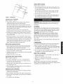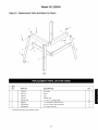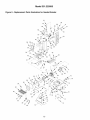
1
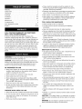
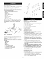
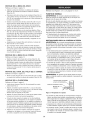
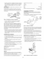
Operator's Manual
CRAFTSMAN+
6 x 48" Belt
9" Disc
SANDER/GRINDER
WITH STAND
Model No.
351.225950
CAUTION:
Read and follow
all Safety Rules and Operating
Instructions before First Use
of this Product.
Sears, Roebuck and Co., Hoffman
2087.00 Draft (06/30/98)
Estates, IL 60179 U.S.A.
Warranty .......................................
2
Safety Rules ....................................
2
Unpacking
.....................................
3-4
4-5
Operation ....................................
Maintenance ....................................
5-7
7
Espa_ol ....................................
• Extension cords should have a grounding prong and the three
wires of the extension cord should be of the correct gauge.
3
Assembly .....................................
Installation ....................................
Troubleshooting .................................
Parts Illustration and List ........................
• Proper electrical receptacle should be available for tool.
Three prong plug should be plugged directly into properly
grounded, three-prong receptacle.
• Keep visitors at a safe distance from work area.
• Keep children out of workplace. Make workshop childproof.
Use padlocks, master switches or remove switch keys to
prevent any unintentional use of power tools.
TOOL SHOULD BE MAINTAINED
8
9-11
• Always unplug tool prior to inspection.
12-19
• Consult manual for specific maintaining
procedures.
and adjusting
• Keep tool lubricated and clean for safest operation.
• Remove adjusting tools. Form habit of checking to see that
adjusting tools are removed before switching machine on.
FULL ONE YEAR WARRANTY
ON CRAFTSMAN
BELT & DISC SANDER/GRINDER
• Keep all parts in working order. Check to determine that the
guard or other parts will operate properly and perform their
intended function.
If within one full year from the date of purchase, this
Craftsman sander/grinder fails due to a defect in material or
workmanship, Sears will repair it free of charge. Warranty service is available by contacting Sears in-home major brand
repair service.This warranty gives you specific legal rights and
you may also have other rights which vary from state to state.
• Check for damaged parts. Check for alignment of moving
parts, binding, breakage, mounting and any other condition
that may affect a tool's operation.
• A guard or other part that is damaged should be properly
repaired or replaced. Do not perform makeshift repairs.
(Use parts list provided to order replacement parts.)
If this sander/grinder is used for commercial purposes, this
warranty applies for only 90 days from the date of purchase.
Sears, Roebuck and Co., Dept. 817WA, Hoffman Estates, IL
60179
KNOW
HOW TO USE TOOL
• Use right tool for job. Do not force tool or attachment to do
a job for which it was not designed.
• Disconnect tool when changing belt or abrasive disc.
WARNING:
For your own safety, read all of the instructions
and precautions before operating tool.
• Avoid accidental start-up. Make sure that the tool is in the
"OFF" position before plugging in.
CAUTION:
Always follow proper operating procedures as
defined in this manual even if you are familiar with use of this
or similar tools. Remember that being careless for even a
fraction of a second can result in severe personal injury.
• Do not force tool. It will work most efficiently at the rate for
which it was designed.
BE PREPARED
• Keep hands away from moving parts and sanding surfaces.
• Never leave tool running unattended. Turn the power off
and do not leave tool until it comes to a complete stop.
FOR JOB
• Do not overreach. Keep proper footing and balance.
• Wear proper apparel. Do not wear loose clothing, gloves,
neckties, rings, bracelets or other jewelry which may get
caught in moving parts of machine.
• Never stand on tool. Serious injury could occur if tool is
tipped or if belt or disc are unintentionally contacted.
• Know your tool. Learn the tool's operation, application and
specific limitations.
• Wear protective hair covering to contain long hair.
• Wear safety shoes with non-slip soles.
• Use recommended accessories (refer to page 11). Use of
improper accessories may cause risk of injury to persons.
• Wear safety glasses complying with United States ANSI
Z87.1. Everyday glasses have only impact resistant lenses.
They are NOT safety glasses.
• Handle the workpiece correctly. Protect hands from possible injury.
• Wear face mask or dust mask if operation is dusty.
• Be alert and think clearly. Never operate power tools when
tired, intoxicated or when taking medications that cause
drowsiness.
• Turn machine off if it jams. Belt jams when it digs too
deeply into workpiece. (Motor force keeps it stuck in the
work.)
PREPARE
• Support workpiece with miter gauge, belt platen or work
table.
WORK
AREA
FOR JOB
, Keep work area clean. Cluttered work areas invite accidents.
• Maintain 1/16"maximum clearance between table and sanding belt or disc.
, Do not use power tools in dangerous environments. Do not
use power tools in damp or wet locations. Do not expose
power tools to rain.
CAUTION:
Think safety? Safety is a combination of operator
common sense and alertness at all times when tool is being
used.
, Work area should be properly lighted.
WARNING:
Do not attempt to operate tool until it is completely assembled according to the instructions.
2
Refer to Figures 1 and 2.
Check for shipping damage. If damage has occurred, a claim
must be filled with carrier. Check for completeness.
Immediately report missing parts to dealer.
The grinder comes assembled as one unit. Additional parts
which need to be fastened to grinder, should be located and
accounted for before assembling.
A Abrasive and aluminum disc with set screw
B Disc guard
C Disc dust chute
D Disc with attached trunnions
E Work stop
5
F Belt table assembly
G Belt dust chute
Figure 2 - Unpacking
6
7
8
Stand
H Miter gauge assembly
Parts bag includes: two handles, three 1A-20 x W' washer
head screws, one 10-1.50 x 25mm socket head bolt, three
lOmm flat washers, and four #10-24 x 3/8"washer head
screws.
CAUTION: Do not attempt assembly if parts are missing.
Use this manual to order replacement parts.
TOOLS
NEEDED
While sanding or adjusting your belt and disc sander/grinder,
you will need the following tools:
• 10 and 17mm Wrench
• 2.5, 3, 4, 5, 6 and 8mm Hex wrenches
G
• Combination
B
Square
• Phillips screwdriver
ASSEMBLE
DISC TABLE
Refer to figure 9, page 10.
• Attach disc guard to end shield (Key No. 23) using three
washer head screws (Key No. 27).
H
Figure 1 - Unpacking
• Remove tape from key and armature (Key Nos. 21 and 20).
Slide aluminum disc with abrasive (Key Nos. 29 and 30)
onto armature with groove in disc aligned with key in armature.
Sander
The stand comes unassembled and packed along with the
sander in the same box. Locate and identify all parts before
attempting assembly (Refer to Figure 2).
• Slide disc dust chute (Key No. 28) onto disc guard from
below the 9" disc with exhaust port to rear of tool. Secure
dust chute to disc guard with two washer head screws (Key
CAUTION:
Do not attempt assembly if parts are missing.
Follow assembly instructions. Use parts list to order replacement parts.
No. 25).
2
Brace (4)
3
Leg (4)
• Slide disc table with attached trunnions (Key Nos. 32
through 35) onto the raised bosses on each side of disc
guard. Mount two handles and flat washers (Key Nos. 36
and 37) through trunnions into threaded holes on each side
of disc guard.
4
Rubber foot (4)
• Locate table in desired position and secure with handles.
5
8/18-18V2" Carriage bolt (24)
• Be sure the gap between the disc and disc table is 1A8"or less.
6
8/18"-18Washer Head Hex nut (24)
7
8-1.25 x 50mm Hex head bolts (4)
8
8-1.25mm Hex nuts (4)
• If an adjustment is necessary, loosen set screw (Key No.
31) in aluminum disc through the opening at top-rear of
disc guard. Position disc 1/1_"or less from edge of table.
Secure disc with set screw.
1 Top Frame (4)
ASSEMBLE
BELT TABLE
Refer to figure 9, page 10.
• Slide belt table assembly (Key No. 46) into trunnion groove
in pivot bracket (Key No. 38). Mount using socket head bolt
and flat washer (Key Nos. 41 and 37). Locate table in
desired position. Be sure that gap between belt table and
belt is 1/18"or less. Tighten bolt securely.
3
ASSEMBLE
BELT DUST
CHUTE
Refer to figure 9, page 10.
Properly Grounded Outlet __=_i}
Grounding Prong.
• Mount belt dust chute (Key No. 40) to platen using two
washer head screws (Key No. 25).
ASSEMBLE STAND
3-Prong Plug __'__
Refer to Figure 8, page 9.
Figure 3 - 3-Prong Receptacle
Install rubber foot (Key No. 4) by pressing onto all four legs
(Key No. 3).
• Plug must be plugged into matching outlet that is properly
installed and grounded in accordance with all local codes
and ordinances. Do not modify plug provided. If it will not fit
in outlet, have proper outlet installed by a qualified
electrician.
Attach one top frame (Key No. 1) to one pair of legs (Key
No. 3) using carriage bolts and hex nuts (Key Nos. 5 and
6). Repeat for second pair of legs.
Attach one brace (Key No. 2) to each pair of legs using carriage bolts and hex nuts.)
• Inspect tool cords periodically, and if damaged, have
repaired by an authorized service facility.
Connect the two leg sets with the two remaining top
frames. Make sure that the square holes in the legs align
with the square holes in the top frame. Also make sure that
the slots on top of the frame members are aligned at each
corner. Secure frames to legs using carriage bolts and hex
nuts.
• Green (or green and yellow) conductor in cord is the
grounding wire. If repair or replacement of the electric cord
or plug is necessary, do not connect the green (or green
and yellow) wire to a live terminal.
• Where a 2-prong wall receptacle is encountered, it must be
replaced with a properly grounded 3-prong receptacle
installed in accordance with National Electric Code and
local codes and ordinances.
Attach the two remaining braces by aligning the square
holes in the legs and the braces. Insert carriage bolts and
secure with hex nuts.
WARNING:
electrician.
A temporary 3-prong to 2-prong grounding adapter (see
Figure 4) is available for connecting plugs to a two pole outlet
if it is properly grounded.
Refer to Figures 3, 4, 5, 6, and 8, page 4, 5 and 9.
POWER
This work should be performed by a qualified
SOURCE
Grounding Lug.
WARNING:
Do not connect grinder to the power source until
all assembly steps have been completed.
Adapter ..._%_
The motor is designed for operation on the voltage and frequency specified. Normal loads will be handled safely on voltages not more than 10% above or below specified voltage.
Running the unit on voltages which are not within range may
cause overheating and motor burn-out. Heavy loads require
that voltage at motor terminals be no less than the voltage
specified on nameplate.
•
3-Prong Plug_
Make Sure
This Is
Connected
_
To A Known
Ground
2-Prong
Receptacle
Figure 4 - 2-Prong Receptacle
with Adapter
• Do not use a 3-prong to 2-prong grounding adapter unless
permitted by local and national codes and ordinances.
Power supply to the motor is controlled by a single pole
locking rocker switch. Remove the key to prevent unauthorized use.
GROUNDING
_
(A 3-prong to 2-prong grounding adapter is not permitted in
Canada.) Where permitted, the rigid green tab or terminal on
the side of the adapter must be securely connected to a
permanent electrical ground such as a properly grounded
water pipe, a properly grounded outlet box or a properly
grounded wire system.
INSTRUCTIONS
WARNING:
Improper connection of equipment grounding
conductor can result in the risk of electrical shock. Equipment
should be grounded while in use to protect operator from
electrical shock.
• Many cover plate screws, water pipes and outlet boxes are
not properly grounded. To ensure proper ground, grounding
means must be tested by a qualified electrician.
• Check with a qualified electrician if grounding instructions
are not understood or if in doubt as to whether the tool is
properly grounded.
EXTENSION
• This tool is equipped with an approved 3-conductor cord
rated at 150V and a 3-prong grounding type plug (Figure 3)
for your protection against shock hazards.
CORDS
• The use of any extension cord will cause some drop in voltage and loss of power.
• Wires of the extension cord must be of sufficient size to
• Grounding plug should be plugged directly into a properly
installed and grounded 3-prong grounding-type receptacle,
as shown (Figure 3).
carry the current and maintain adequate voltage.
• Use the table to determine the minimum wire size (A.W.G.)
extension cord.
• Do not remove or alter grounding prong in any manner. In
the event of a malfunction or breakdown, grounding provides a path of least resistance for electrical shock.
• Use only 3-wire extension cords having 3-prong grounding
type plugs and 3-pole receptacles which accept the tool
plug.
WARNING:
Do not permit fingers to touch the terminals of
plug when installing or removing from outlet.
• If the extension cord is worn, cut, or damaged in any way,
replace it immediately.
4
Extension Cord Length
Wire Size ..................................
A.W.G.
Up to 25 ft.....................................
18
NOTE: Using extension cords over 25 ft. long is not
recommended.
MOTOR
The sander/grinder is assembled with motor and wiring
installed as an integral part of the tool. The electrical wiring
schematic is shown in Figure 5.
The 120 Volt AC permanently split capacitor motor has the following specifications:
Horsepower (Maximum Developed) .................
11/2
Voltage ......................................
120
Amperes .....................................
Hertz ........................................
8.0
60
Phase .....................................
RPM .......................................
Figure 6 - Mounting Sander
to Stand
Single
3450
Rotation (viewed from left side) ...............
Clockwise
Refer to Figures 7 and 9, pages 6 and 10.
ELECTRICAL
CONNECTIONS
WARNING:
Make sure unit is off and disconnected from
DESCRIPTION
Craftsman 6" Belt and 9" Disc Sander is constructed of
power source before inspecting any wiring.
rugged die cast aluminum and cast iron providing stability and
vibration-free operation. The 6 x 48" belt and 9" diameter disc
are used to sand, deburr, bevel and grind large workpieces of
wood, plastic and metal.
The motor is installed and wiring connected as illustrated in
the wiring schematic (see Figure 5).
Switch_i_
Black
-o.....\
Relay
-_
ToPower
"Green \,._____/_"_
The 6 x 48" belt housing can be pivoted from vertical to horizontal for sanding large, straight workpieces. The belt assembly includes a tilting, cast iron table with miter gauge and dust
collection chute.
The 9" diameter disc can be used to sand or bevel surfaces
with the use of 0 to 45 ° scaled aluminum table. The 9" diam-
FTo Motor
_
_
S
Capacitor
eter disc assembly includes a tilting table with miter gauge
slot and dust collection chute.
The 3" diameter idler drum permits the sanding of contoured
shapes and finishes by positioning the adjustable platen from
a horizontal to vertical position.
I
Figure 5 - Wiring Schematic
The two collection chutes with adaptable exhaust ports allow
for quick removal of dust. The adjustable miter gauge can be
used on both the belt and disc tables for guiding the workpiece at a desired angle while sanding.
The motor is assembled with an approved three conductor
cord to be used on 120 volts as indicated. The power supply
to the motor is controlled by a single pole locking rocker
switch.
SPECIFICATIONS
The power lines are inserted directly onto the switch. The
green ground line must remain securely fastened to the frame
to properly protect against electrical shock.
• Remove the key to prevent unauthorized
MOUNTING
SANDER
Belt size .............................
6 x 48", 80 grit
Belt platen area ..........................
Belt table dimensions .......................
use.
Belt table tilts ..............................
TO STAND
0 to 60 °
Belt dust chute diameter .........................
Refer to Figures 6 and 8, pages 5 and 9.
Install sander on the stand.
Align mounting holes on sander with slots on top frame
(Fig. 8, Key No. 1).
2700 FPM
Disc diameter ............................
Disc table dimensions ......................
9", 80 grit
57/8x 117/8''
0 to 45 °
Disc dust chute diameter ........................
Disc speed ..............................
Base dimensions ........................
Switch ...................
Motor ......
13/4"
3450 RPM
131/2x 138/8''
120 Volts, SP, Locking rocker
11/2HP(max. developed) 3450 RPM, 8.0 AMPS
Weight ....................................
5
21/2''
Belt speed ..............................
Disc table tilts ..............................
Secure sander to stand on all four corners using hex head
bolts and hex nuts (Fig. 8, Key Nos. 8 and 9).
71/8x 167/8''
57/8x 97/8''
105 Ibs
WARNING:
Operation of any power tool can result in foreign
objects being thrown into the eyes, which can result in severe
eye damage. Always wear safety goggles complying with
United States ANSI Z87.1 (shown on package) before commencing power tool operation. Safety goggles are available at
Sears retail stores or catalog.
CAUTION:
SAFETY
Rotate belt by hand to check tracking. Belt should ride centered on drive and idler drums. Adjust thumb nut (Key No.
75) as needed to center belt on drums. Tighten hex nut
(Key No. 39). If adjustment of thumb nut does not provide
desirable tracking, adjust the stud (Key No. 72) using an
allen wrench. To adjust stud, loosen hex nut (Key No. 39)
and turn stud counterclockwise to move belt to the right or
clockwise to move belt to the left until belt rides centered
Always observe following safety precautions.
PRECAUTIONS
on drive and idler drums. Tighten hex nut while holding the
stud in place.
• Whenever adjusting or replacing any parts on the tool, turn
switch OFF and remove the plug from power source.
Mount belt dust chute using washer head screws.
Recheck table handles. They must be tightened securely.
ADJUSTING
Make sure all guards are properly attached. All guards
should be securely fastened.
Refer to Figure 9, page 10.
• Loosen socket head bolt (Key No. 54) that is threaded
pivot bracket (Key No. 38).
Make sure all fasteners are tight and have not vibrated
loose.
into
• Tilt belt assembly to desired position (from horizontal to
vertical). Secure belt assembly position by tightening socket
head bolt in pivot bracket.
With power disconnected, test operation by hand for clearance and adjust if necessary.
Always wear eye protection or face shield.
ADJUSTING
Make sure abrasive belt always tracks properly. Correct
tracking gives optimum performance.
BELT TABLE
Refer to Figure 9, page 10.
• To adjust belt table angle, loosen socket head bolt
(Key No. 41 ).
After turning switch on, always allow belt to come up to full
speed before sanding or grinding.
Be sure motor runs clockwise on disc side. Abrasive belt
must travel down.
• Tilt belt table to desired position. Adjust for 1/1_"maximum
clearance between the belt and the table. Secure by tightening socket head bolt.
Avoid kickback by sanding in accordance with the directional arrows.
HORIZONTAL
Keep your hands clear of abrasive belt, disc and all moving
parts.
BELT SANDING
Refer to Figure 9, page 10.
• The belt platen can be tilted from a vertical to a horizontal
position.
For optimum performance, do not stall motor or reduce
speed. Do not force the work into the abrasive.
• Remove the belt table by removing the socket head bolt
and flat washer (Key Nos. 41 and 37). Loosen the socket
head bolt (Key No. 54); tilt the belt platen assembly to the
horizontal position and tighten the socket head bolt to
secure position.
• Idler drum can be used as a contact drum to sand surfaces.
Support workpiece with belt table when sanding with belt,
with disc table when sanding with disc.
Never push a sharp corner of the workpiece rapidly against
the belt or disc. Abrasive backing may tear.
Replace abrasives when they become loaded (glazed) or
frayed.
When grinding metal, move workpiece across abrasive to
prevent heat built up.
WORK STOP
Refer to Figure 9, page 10.
Never attempt wet sanding. If the workpiece becomes too
hot to handle, cool it in water.
ABRASIVE
POSITION
Sanding belt assembly can be adjusted from horizontal to vertical position.
Make sure all moving parts are free and clear of any
interference.
REPLACING
BELT ASSEMBLY
The work stop (Key No 42) can be used instead of the belt
table.
BELT
• Remove socket head bolt and flat washer (Key Nos. 41 and
37) holding belt table on pivot bracket. Remove belt table.
Refer to Figure 9, page10.
• Sanding belt should be replaced when worn, torn, or
glazed. Remove belt dust chute (Key No. 40) by removing
two washer head screws (Key No. 25).
• Mount work stop to pivot bracket using the socket head bolt
and washer (Key Nos. 41 and 37).
• Release belt tension by pushing tension lever (Key No. 63)
toward idler drum. Slide old belt off the drive and idler
Refer to Figure 7, page 7.
SHARPENING
Adjust belt table to desired sharpening angle and tighten
securely. Use belt sander/grinder to notch the back of an
auxiliary piece of wood.
drums (Key Nos. 52 and 66).
NOTE: There may be an arrow on the inside of the belt. The
arrow should point down toward the belt table to ensure that
the splice in the belt will not come apart.
Using a C-clamp, attach auxiliary piece of wood to table. It
acts as a support while sharpening (see Figure 7).
• Slide new belt over the drive and idler drums; center belt on
drums.
Top edge of wood should be less than 1/1_"from abrasive
belt.
• Push tension lever towards drive drum to tension belt.
6
USING
MITER
GAUGE
Refer to Figure 9, page 10.
• The miter gauge is used on both belt and disc tables. Use
the miter gauge for securing the work and holding the proper angle while sanding.
• Adjust angle by repositioning the miter gauge scale (Key
No. 78) and locking it into place with knob (Key No. 79).
• Check accuracy of miter gauge scale.
• Use a combination square to adjust miter gauge square to
disc. Indicator should be at zero. Loosen screw (Key No.
80) and reposition indicator if necessary.
Figure 7 - Sharpening
ABRASIVE BELT FINISHING
Refer to Figure 9, page 10.
•
WARNING:
Finishing flat surfaces: Hold workpiece firmly with both
hands; keep fingers away from abrasive belt.
Use work stop. Work stop is used to position and secure
work being sanded. Keep end butted against work stop and
move work evenly across abrasive belt. Use extra caution
when finishing very thin pieces.
Keep machine and workshop clean. Do not allow sawdust to
accumulate on the tool. Keep the drums clean. Dirt on drums
will cause poor tracking and belt slippage. Operate tool with
dust collector to keep dust from accumulating.
Finishing curved edges: Finish outside curves on flat portion of abrasive belt. Finish inside curves on idler drum portion of abrasive belt.
WARNING:
After sanding wood or nonmetallic material,
always clean dust collector and guards of sawdust before
grinding metal. Sparks could ignite debris and cause a fire.
Finishing end grain: It is more convenient to finish ends of
long workpieces with the abrasive belt in a vertical position.
Be certain motor is kept clean and is frequently vacuumed
free of dust.
Position table on belt side of sander. Lock into position with
socket head bolt and washer (Key Nos. 41 and 37). Move
work evenly across abrasive belt. For accuracy, use miter
gauge. Table may be tilted for beveled work.
ABRASIVE
Use soap and water to clean painted parts, rubber parts and
plastic guards.
LUBRICATION
The shielded ball bearings in this tool are permanently lubricated at the factory. They require no further lubrication.
DISC
• Remove disc table and dust chute. Remove old abrasive
disc by peeling it from the aluminum disc. Removing aluminum disc from motor shaft is not necessary.
• When operation seems stiff, a light coat of automobile-type
wax applied to the belt table and disc table will make it easier to feed the work while finishing.
• Clean aluminum disc if necessary. Select the proper abrasive disc and apply to aluminum disc.
• Do not apply wax to the belt platen. Belt could pick up wax
and deposit it on wheels causing belt to slip.
• Additional abrasive discs are available (See Recommended
Accessories, page 11).
KEEP TOOL
• Replace dust chute and disc table.
ADJUSTING
DISC TABLE
from
CLEANING
Finishing long pieces: remove work stop. Apply only
enough pressure to allow abrasive belt to remove material.
REPLACING
Make certain that the unit is disconnected
power source before attempting to service or remove any
component.
IN REPAIR
• If power cord is worn, cut, or damaged in any way, have it
replaced immediately.
ANGLE
• Replace worn abrasives when needed.
Refer to Figure 9, page 10.
Disc table is adjustable from 0 to 45 ° for beveled work.
• Replace any damaged or missing parts. Use parts list to
order parts.
To adjust the disc table, loosen the two handles (Key No.
36) and pivot to the desired angle.
Use the scale on disc table trunnions to set table from 0 to
45 ° from abrasive disc.
Any attempt to repair motor may create a hazard unless
repair is done by a qualified service technician. Repair service
is available at your nearest Sears store.
When disc table is at desired angle, lock it into position by
securely tightening the handles.
ABRASIVE
DISC FINISHING
Abrasive disc sanding is well suited for finishing small flat
surfaces and convex edges
Move workpiece across down side (right) of abrasive disc.
Abrasive disc moves fastest and removes more material at
outer edge.
For accuracy, use miter gauge.
7
SYMPTOM
Motor will not start
POSSIBLE
CAUSE(S)
CORRECTIVE
ACTION
1. Low voltage
1. Check power line for proper voltage
2. Open circuit in motor or loose
connections
2. Inspect all lead connections on motor for loose or
open connection
Motor will not start;
fuses blown or circuit
1. Short circuit in line cord or plug
1. Inspect line cord or plug for damaged insulation and
shorted wires
breakers are tripped
2. Short circuit in motor or loose
connections
3. Incorrect fuses or circuit breakers in
2. Inspect all lead connections on motor for loose or
shorted terminals or worn insulation on wires
3. Install correct fuses or circuit breakers
power line
Motor fails to develop full
power (power output of
motor decreases rapidly
with decrease in voltage
at motor terminals)
1. Power line overloaded with lights,
appliances and other motors
2. Undersize wires or circuits too long
3. General overloading of power
company's facilities
3. Request a voltage check from the power company
Motor overheats
Motor overloaded
Reduce load on motor
Motor stalls
(resulting in blown
fuses or tripped circuit
breakers)
1. Short circuit in motor or loose
connections
1. Inspect connections in motor for loose or shorted
terminals or worn insulation on lead wires.
2. Low voltage
3. Incorrect fuses or circuit breakers in
power line
4. Motor overload
2. Correct the low line voltage conditions
3. Install correct fuses or circuit breakers
Machine slows down
while operating
Applying too much pressure to workpiece
Ease up on pressure
Abrasive belt runs off top
wheel
Not tracking properly
See operation "Replacing Abrasive Belt"
8
1. Reduce the load on the power line
2. Increase wire sizes, or reduce length of wiring
4. Reduce load on motor
Model 351.225950
Figure 8 - Replacement Parts Illustration for Stand
1
\
6
;
3
KEY
NO.
PART NO.
DESCRIPTION
1
1264.00
2
1265.00
Top frame
Brace
3
1266.00
4
1267.00
5
STD533105
6
8428.00
5/1_'-18x W' Carraige bolt*
5/1_"-18Washer Head Hex Nut
7
STD835050
8-1.25 x 50mm Hex head bolts*
4
8
STD840812
8-1.25mm Hex nuts*
4
QTY.
4
Leg
Rubber foot
Standard hardware item available locally
9
4
4
32
32
Model 351.225950
Figure 9 - Replacement Parts Illustration for Sander/Grinder
51
12
16
23
5
1
37!
14
i
33
12
37
36
74
10
3
KEY
NO.
KEY
NO.
PART NO.
DESCRIPTION
46
47
8387.01
8658.00
Belt Table Asm. (Key Nos. 43-45)
Motor Fan
1
1
48
49
50
51
8114.00
8388.00
8389.00
8390.00
Relay Bracket
Indicator
6 x 12mm Dowel Pin
1
1
1
1
2
Forming Screw
Capacitor
Capacitor Cap
52
53
54
8391.00
8392.00
1822.00
Pivot Stop Bracket
Drive Drum
Platen
8-1.25 x 20mm Socket Head Bolt
1
1
1
6
1
2
55
56
STD852008
8393.00
8mm Lock Washer*
5
Capacitor Clamp
#10-24 x _A"Washer Head Screw
#10 Serrated Washer*
Base Cover
1
8
1
1
57
58
59
0316.00
8394.00
8395.00
Platen Stop Bracket
8-1.25 x 12mm Set Screw
1
7
Stop Rod
1
1
Switch with Key
Strain Relief Plate
Strain Relief
Line Cord
1
1
1
1
8396.02
8397.02
6182.00
1
1
Switch Plate
60
61
62
Bumper
Idler Drum Bracket
Spring
6-1.0 x 30mm Socket Head Bolt
1
1
63
64
65
8398.00
8399.00
STD851006
Tension Lever
Handle
6mm Flat Washer*
1
1
1
Armature
1
2
2
Bearing 6201ZZ
Idler Drum Shaft
2
1
8370.01
Bearing 6205ZZ
End Shield
8400.00
0520.00
8401.00
1
1
66
67
68
Idler Drum
5x5x25mmKey
24
25
928015
1477.00
Abrasive Belt
#10-24 x 3/8"Washer Head Screw
1
7
69
70
71
0519.00
8402.00
8403.00
3-AM1-12 Retaining Ring
Rubber Bushing
Collar
2
2
2
26
27
8371.01
6403.00
8412.00
STD852006
Stud
6mm Lockwasher*
1
1
8372.00
8373.00
1732.00
1
6
1
72
73
28
29
30
Disc Guard
_A-20 x 1/2"Washer Head Screw
Disc Dust Chute
8411.00
8413.00
8410.00
Miter Gauge Asm. (Nos. 75-80)
Thumb Nut
Indicator
1
2
1
1210.00
8374.00
8375.00
1
1
3
74
75
76
31
32
33
Aluminum Disc
Abrasive Disc
5-0.8 x 5mm Set Screw
Disc Table
Left Trunnion
1
1
1
1
8376.00
8655.00
8378.00
Right Trunnion
6-1.0 x 15mm Flat Head Screw
Handle
1
4
2
8407.00
8408.00
8409.00
STD510802
Miter Gauge Bar
Miter Gauge Scale
34
35
36
77
78
79
80
Knob (Ext. Threads)
#8-32 x W' Pan Head Screw*
1
1
A
2087.00
Operator's Manual
1
37
38
39
STD851010
8379.01
5153.00
40
41
42
8380.01
1002.00
8381.00
10mm Flat Washer*
Pivot Bracket
6 x 1.0mm Fiber Hex Nut
Belt Dust Chute
3
1
1
1
Recommended
10-1.5 x 25mm Socket Head Bolt
1
A
Abrasive Belts 6 x 48" (Fine) 120 Grit
928014
43
44
45
8382.00
8383.00
8384.00
Work Stop
Belt Table
Belt Table Trunnion
1
1
1
A
Abrasive Belts 6 x 48" (Coarse) 50 Grit
928016
A
Abrasive Disc 9" (Fine) 150 Grit
928239
4 x 10mm Spring Pin
2
A
Abrasive Disc 9" (Medium) 100 Grit
928240
A
Abrasive Disc 9" (Coarse) 60 Grit
928241
A
Steel Stand
922250
A
Abrasive Cleaner
922744
PART NO.
DESCRIPTION
1
2
8366.02
1058.00
3
4
5
6
8367.01
STD512510
STD551125
STD541025
Stator with Housing
Grommet
Base
7
8
8187.00
0358.00
Relay
#8-16 x 11/2"Thread
9
10
0295.00
1607.00
11
12
13
9567.00
1605.00
STD551210
14
15
16
8178.00
8173.00
8066.00
17
18
19
8172.00
1601.00
0067.00
20
21
22
8368.01
0975.00
2443.00
23
*
A
1A-20 x 1" Pan Head Screw*
1A" Lock Washer*
W'-20 Hex Nut*
QTY.
1
1
1
12
12
4
Standard hardware item available locally
Not shown
11
QTY.
Accessories
LIJADORA/ESIVlERILADORA
CON PLATAFORIVlA
•
Use una cubierta
protectora
para el cabello,
para sujetar el
cabello largo.
•
Use zapatos
•
Use galas de seguridad que cumplan con ANSI Z87.1 de
Estados Unidos. Los anteojos corrientes tienen solamente
Correa de 15,2 × 121,9 cm
de seguridad
lentes resistentes
con suelas antideslizantes.
NO son anteojos
de seguridad.
Disco de 22,9 cm
•
Use una mascara para la cara o una mascara
si la operaci6n de lijado produce polvo.
para el polvo,
Modelo No.
351.225950
•
Est6 alerta y piense claramente.
herramientas
PRECAUCION:
Lea este manual y siga las
Reglas de Seguridad y las Instrucciones
de
Operacidn,
antes de usar este producto por
primera vez.
PREPARACION
TRABAJO
Ingles .............................................
2-8
Ilustraci6n y Lista de Partes ............................
•
No use herramientas
mec_.nicas en ambientes peligrosos. No
use herramientas
mec_tnicas en lugares hQmedos o mojados.
13-14
Instalaci6n ........................................
14-15
Operaci6n ........................................
16-18
Identificaci6n
.......................................
de Problemas
debe estar iluminada
a la Iluvia.
El Area de trabajo
•
Tiene que haber disponible un recept_tculo electrico adecuado
para la herramienta.
El enchufe de tres puntas se tiene que
•
•
Los cordones
de tres puntas
deben
tener una punta de co-
nexi6n a tierra y los tres alambres
deben ser del calibre correcto.
del cord6n de extensi6n
Mantenga
de extensi6n
adecuadamente.
a los visitantes
a una distancia
prudente
del Area
de trabajo.
18
.............................
mec_.nicas
enchufar directamente
en un recept_.culo
conectado a tierra correctamente.
13
Montaje ..........................................
las herramientas
•
12-13
........................................
DEL AREA PARA EJECUTAR EL
Mantenga el _trea limpia. Las _.reas de trabajo desordenadas
atraen accidentes.
12
Reglas de Seguridad ................................
est6
•
9-11
Garantia ............................................
Mantenimiento
Nunca opere
mec_.nicas cuando est6 cansado, intoxicado o cuando
tomando medicamentos
que causan somnolencia.
No exponga
Desempaque
al impacto.
•
19
Mantenga a los ni_os fuera del lugar de trabajo. Haga que
su taller sea a prueba de niSos. Use candados, interruptores
principales o remueva las Ilaves del interruptor para evitar el
uso no intencional de las herramientas
mec_.nicas.
ES IMPORTANTE
UN ANO COMPLETO
ESMERILADORA
Siesta
DE GARANTIA
DE CORREA
lijadora/esmeriladora
PARA
Y DISCO
Craftsman
CRAFTSMAN
falla debido a un defecto
en el material o en la mano de obra dentro de un aSo completo
a partir de la fecha de compra, devuelvala al centro de servicio
de Sears m_.s cercano y Sears la reparar_, gratis. Si esta lijadora/
esmeriladora
se usa para prop6sitos comerciales,
esta garantia
ser_. v_.lida por 90 dias solamente,
Esta garantia
le da derechos
puede tener otros derechos
•
Desenchufe
•
Consulte el manual para informarse sobre los procedimientos
de mantenimiento
y ajuste especificos.
•
Mantenga
la herramienta
operaci6n
m_.s segura.
•
a partir de la fecha de compra.
legales
especificos
Hoffman
•
Estates, IL 60179
siempre
la herramienta
antes de encender
Mantenga todas las partes
determinar que el protector
mente y har_.n el trabajo
•
ADVERTENClA:
instrucciones
Para su propia seguridad,
y las precauciones
antes de operar la herramienta.
•
que, si no se tiene cuidado
de segundo,
personales
Use ropa apropiada.
No use ropa suelta,
anillos, pulseras u otras joyas que puedan
las partes m6viles de la m_.quina.
guantes,
quedar
graves.
Si hay una protecci6n
o cualquier otra condici6n
de la herramienta.
o cualquier
otra parte da_ada,
que
tiene
las partes de repuesto.)
EL OPERADOR
HERRAMIENTA
corbatas,
cogidas
la m_.quina.
listas para funcionar. Revise para
u otras partes operar_.n correcta-
Revise para verificar si hay partes daSadas. Revise para
verificar el alineamiento
de las partes movibles, si hay atas-
para ordenar
ESTE PREPARADO PARA EL TRABAJO
•
una
que repararse correctamente
o cambiarse. No haga reparaciones provisorias. (Use la lista de partes que viene incluida
por aunque sea una fracci6n
se pueden producir lesiones
y limpia para obtener
especifico.
camiento, roturas y montaje
pudiera afectar la operaci6n
lea todas las
PRECAUClON:
Siempre siga los procedimientos
de operaci6n
correctos, tal como se definen en este manual, aun cuando est6
familiarizado con el uso de esta o de otras herramientas similares.
Recuerde
lubricada
antes de inspeccionarla.
Remueva las herramientas
de ajuste. F6rmese el h_.bito de
revisar para verificar si las herramientas
de ajuste se han
removido
y tambien
que varian de estado a estado.
Sears, Roebuck and Co., Dept. 817WA,
MANTENER LAS HERRAMIENTAS
LA LIJADORA/
•
Use la herramienta
correcta para el trabajo. No fuerce la
herramienta,
o el accesorio, ni los use para un trabajo para
el cual no han sido diseSados.
•
Desconecte
en
la herramienta
disco abrasivo.
12
DEBE SABER COMO USAR LA
cuando
cambie
la correa
o el
•
•
Evite el arranque
por accidentes.
de la herramienta
enchufarla.
est,. en la posici6n
No fuerce
la herramienta.
a la velocidad
AsegOrese
que el interruptor
OFF (apagado)
Trabajarb, en la forma
antes de
m_.s eficiente
para la cual se dise56.
las manos alejadas
G
•
Mantenga
de las partes m6viles.
•
Nunca deje que una herramienta funcione sola. Descon_ctela
y no se vaya hasta que se detenga completamente.
•
No trate de alcanzar
demasiado
lejos. Mantengase
B
firme y
equilibrado.
•
Nunca se pare en la herramienta. Se pueden producir lesiones
graves si la herramienta se inclina, o si se toca el disco o la
correa
•
•
Conozca su herramienta. Aprenda la operaci6n
mienta, aplicaci6n y limitaciones especificas.
Use los accesorios
que se recomienda.
Si se usan accesorios incorrectos,
riesgo de lesiones personales.
•
Figura 1 - Desempaque
de la herra-
PRECAUCION:
Consulte
la p_.gina 11.
E
Protejalas
de la lijadora
No trate de montarla
Siga las instrucciones
del montaje.
ordenar las partes de repuesto.
se puede producir
Deje las manos libres para operar la m_.quina.
posibles
•
I
H
pot accidente.
de
lesiones.
1
Bastidor
superior
2
Soporte
(4)
si hay partes que faltan.
Use la lista de partes
(4)
3
Pata (4)
Desconecte
la m_.quina si se atasca. La cortadora se atasca
cuando penetra muy profundamente
en la pieza de trabajo.
4
Pie de goma (4)
(La fuerza del motor la mantiene
5
Perno de coche,
8/18-18W', (24)
6
Tuerca hexagonal
con cabeza
de arandela,
7
Pernos de cabeza
hexagonal,
8-1,25 x 50 mm, (4)
8
Tuercas
pegada a la pieza de trabajo.)
•
Soporte la pieza de trabajo con la guia de ingletes,
de la correa o la mesa de trabajo.
•
Mantenga
la platina
un espacio libre m_.ximo de 1,6 mm entre la mesa
y la correa
para
hexagonales,
8/18"-18, (24)
8-1,25 mm, (4)
o el disco para lijar.
PRECAUClON:
iPiense en la seguridad! La seguridad es una
combinaci6n
de sentido comQn del operador y de estar alerta
en todo momento cuando se estb, usando la herramienta.
ADVERTENClA:
No trate de operar la herramienta
hasta que
este completamente
montada segun las instrucciones.
Refierase
Verifique
alas
Figuras
si han ocurrido
1 y 2.
daSos durante
el envio. Si ha ocurrido
algQn daSo, se debe entablar un reclamo con la compaSia
transportes. Verifique que la orden est6 completa. Informe
inmediatamente
al distribuidor
de
si hay partes que faltan.
La lijadora/esmeriladora
viene montada como una unidad. Se
deben encontrar las partes adicionales
que se van a fijar a la
lijadora y asegurarse
montaje.
que no falte ninguna
A
Disco abrasivo
B
Protecci6n
y de aluminio
C
Canal del polvo del disco
con tornillo
el
de fijaci6n
Figura 2 - Desempaque
de la plataforma
del disco
D
Disco con los muSones
E
Tope del trabajo
F
Conjunto
G
Canal del polvo de la correa
H Conjunto
antes de efectuar
adjuntos
PRECAUCION:
Use este manual
de la mesa de la correa
HERRAMIENTAS
de la guia de ingletes
La bolsa con las partes incluye:
No trate de montarlo si hay partes que faltan.
para ordenar partes de repuesto.
dos mangos,
tres tornillos
de
NECESARIAS
Cuando lije o ajuste la lijadora/esmeriladora
necesitar_, las herramientas
siguientes:
cabeza de arandela de 1A-20 x W', un perno de cabeza hueca de
10-1,50 x 25 mm, tres arandelas planas de 10 mm y cuatro torniIlos de cabeza de arandela #10-24 x 3/8".
•
Llave de 10 y 17 mm
•
Llaves hexagonales
La plataforma viene desmontada y empacada junto con la lijadora en la misma caja. Encuentre e identifique todas las partes
•
Escuadra
antes de tratar de montarla
•
Destornillador
(Refierase
a la Figura 2).
13
de disco y correa
de 2,5, 3, 4, 5, 6 y 8 mm
de combinaci6n
Phillips
MONTAJE DE LA MESA DEL DISCO
Refierase
•
a la Figura 9, p_.gina 10.
Adjunte la protecci6n del disco a la defensa del extremo
(Clave No. 23) usando tres tornillos de cabeza de arandela
Refierase
(Clave No. 27).
•
Deslice
con la ranura en el disco alineada
ADVERTENCIA:
con
El motor ha sido diseSado
el canal del polvo del disco (Clave No. 28) en la pro-
la mesa del disco con los muSones
adjuntos
•
•
la mesa en la posici6n
deseada
y asegQrela
sean menos que el voltaje especificado.
•
Remueva
INSTRUCClONES
AsegQrese que el espacio libre entre el disco y la mesa del
disco sea de 1,6 mm o menos.
ADVERTENClA:
hacer ajustes,
suelte el tornillo
de fijaci6n
el disco a 1,6 mm, o menos,
con el tornillo de fijaci6n.
•
del borde de la mesa. AsegQrelo
•
38). M6ntelo usando el perno de cabeza hueca y la arandela
plana (Clave Nos. 41 y 37). Ubique la mesa en la posici6n
•
deseada. AsegQrese que el espacio libre entre la mesa de la
correa y la correa sea de 1,6 mm o menos. Apriete el perno
•
en forma segura.
a la Figura 9, p_.gina 10.
de cabeza
Si las instrucciones
Esta herramienta
a la Figura 8, p_.gina 9.
•
contra
de conexi6n
el pie de goma (Clave No. 4) presionando
(Clave No. 25).
las cuatro
de choque
a tierra e instalado
electrico.
correctamente,
directamente
a tierra de 3 puntas, conectado
como se muestra
(Figura 3).
No remueva ni altere la punta de conexi6n a tierra de ninguna
manera. En el caso de una falla o de una descarga disruptiva,
el camino
de menor
resisten-
No permita que los dedos toquen los termicuando se est_.n instalando o removiendo del
Punta de conexi6n
a
Enchufe de
3apuntas
tierra
t__
Figura 3 - Recept_culo
•
hexagonales.
de 3 puntas
Conecte los dos conjuntos de patas con los dos bastidores
superiores restantes. Asegurese
que los agujeros cuadrados
•
•
hexagonales.
con las tuercas
Inspeccione
los cordones
si est_n da_ados
Adjunte los dos soportes restantes, alineando los agujeros
cuadrados en las patas yen los soportes. Inserte los pernos
de coche y asegQrelos
se debe enchufar
en el tomacorriente
correspon
fique el enchufe que se proporciona
Si no calza en el tomaco
rriente haga que un electricista calificado instale uno correcto
parte superior de los miembros del bastidor queden alineadas
en cada esquina. Asegure los bastidores en las patas usando
los pernos de coche y las tuercas
El enchufe
diente que debe estar instalado correctamente
y conectado a
tierra segtJn todos los cddigos y reglamentos locales No modi
en las patas queden alineados con los agujeros cuadrados en
el bastidor superior. Tambien asegQrese que las ranuras en la
•
de 3 conduc-
(Clave No. 2) a cada par de patas usando
los pernos de coche y las tuercas
•
con un cord6n
a
tomacorriente.
onales (Claves Nos. 5 y 6). Repita el procedimiento para el segundo par de patas.
un soporte
un choque
a tierra no se entienden
a tierra se debe enchufar
de conexi6n
Adjunte un bastidor superior (Clave No. 1) a un par de patas
(Clave No. 3) usando los pernos de coche y las tuercas hexag-
Adjunte
los peligros
en un recept_.culo
patas (Clave No. 3).
•
contra
Tomacorriente
conectado
correctamente.
Refierase
•
viene equipada
El enchufe
MONTAJE DE LA PLATAFORMA
Instale
al operador
para la conexi6n
protecci6n
ADVERTENClA:
nales o el enchufe
(Clave No. 40) a la plati-
de arandela
para proteger
la conexi6n a tierra proporciona
cia al choque electrico.
MONTAJE DEL CANAL DEL POLVO DE LA CORREA
dos tornillos
el conductor
tores aprobado, con capacidad de 150 V y con un enchufe
de 3 puntas del tipo de conexi6n a tierra (Figura 3) para su
Deslice el conjunto de la mesa de la correa (Clave No. 46)
dentro de la ranura del mu56n en el puntal pivote (Clave No.
na usando
incorrectamente
o si se tienen dudas de que la herramienta
est6 conectada
tierra correctamente,
consulte a un electricista calificado.
a la Figura 9, p_.gina 10.
Monte el canal del polvo de la correa
PARA LA CONEXION A TIERRA
de conexi6n a tierra del equipo, se puede producir un riesgo de
choque electrico. El equipo debe estar conectado a tierra mientras se est,. usando,
electrico.
Refierase
el uso no autorizado.
Si se conecta
(Clave No. 31) en el disco de aluminio a trav_s de la abertura
en la parte superior trasera de la protecci6n del disco. Ponga
Refierase
•
la Ilave para impedir
con los
MONTAJE DE LA MESA DE LA CORREA
•
El abastecimiento
de energia que va al motor est,. controlado con un interruptor oscilante de enclavamiento
unipolar.
mangos.
Si es necesario
para operar con el voltaje y la frecuen-
un calentamiento
excesivo y quemarse el motor. Las cargas
pesadas exigen que el voltaje en los terminales del motor no
(Clave
planas (Clave Nos. 36 y 37) a trav_s de los muSones en los
agujeros roscados en cada lado de la protecci6n del disco.
Ubique
a la
de que se hayan com-
debajo del voltaje especificado. Si se hace funcionar la unidad
con voltajes que no est6n dentro de la gama, se puede producir
Nos. 32 a 35) en las protuberancias
elevadas en cada lado de
la protecci6n del disco. Monte los dos mangos y las arandelas
•
la lijadora/esmeriladora
cia especificados.
Las cargas normales se pueden manejar con
seguridad con voltajes de no m_.s de 10% por encima o por
Asegure el canal del polvo a la protecci6n del disco con dos
tornillos de cabeza de arandela (Clave No. 25).
Deslice
No conecte
fuente de energia sino hasta despues
pletado todos los pasos del montaje.
tecci6n del disco desde debajo del disco de 22,9 cm con el
orificio de escape hacia la parte trasera de la herramienta.
•
Figuras 3, 4, 5, 6, y 8, p_.ginas 14, 15 y 9.
FUENTE DE ENERGIA
Remueva la cinta de la cuSa y de la armadura (Clave Nos. 21
y 20). Deslice el disco de aluminio con el abrasivo (Clave Nos.
29 y 30) en la armadura
la cuSa en la armadura.
•
alas
El conductor
de conexidn
h_galos
de la herramienta
reparar
14
y
autorizado
verde (o verde y amarillo) del corddn es el cable
a tierra Si es necesario reparar o cambiar el cor
ddn electrico o el enchufe no conecte
y amarillo) a un terminal cargado
hexagonales.
periddicamente
por un servicio
el cable verde
(o verde
•
Cuando
se encuentra
un receptb.culo
de pared de 2 puntas,
se
Caballos
de fuerza
(al m_.ximo) .......................
Voltaje .........................................
120
reglamentos
locales.
Amperios ........................................
8,0
Hertz
del National
ADVERTENOIA:
tricista calificado.
Electric
Este trabajo
Code y con los c6digos
debe ser ejecutado
...........................................
por un elec-
bipolar,
Tal6n de tierra.
Adaptador
Enchufe
si est,. conectado
_
.--......_._
de \
U±_ II
\\\
30unt s
Figura 4 - Recept_culo
Rotaci6n
a tierra
CONEXIONES
ELECTRICAS
aUna
conexi6ntierra
El motor se instala y el cableado se conecta segOn la ilustraci6n
en el diagrama de cableado (vea la Figura 5).
desconectada
cualquier
conocida
Aseg_rese
de la fuente
y
antes de inspeccionar
cableado.
A la
fuente de
Negro
Recept_.culo
de 2 puntas
_o_\
de 2 puntas con adaptador
Rele --_
r_egro
energia
o _)
_
M k_----_
locales y nacionales.
Bla_k
-_
Figura 5 - Diagrama
permanente,
tal como una tuberia de agua conectada a tierra
correctamente,
una caja de tomacorriente
conectada a tierra
correctamente
o un sistema de cables conectado a tierra
correctamente.
de los tornillos
de la plancha
de cubierta,
Capacitor
de cableado
El motor se monta con un cord6n
de tres conductores
aprobado
para usarse con 120 voltios, tal como se indica. El abastecimiento de energia que va al motor esta controlado pot un interruptor
oscilante
las tuberias
de enclavamiento
unipolar.
de agua y las cajas de tomacorriente
no estb, n conectados a
tierra correctamente.
Para asegurar una conexi6n a tierra co-
Las lineas de energ[a electrica se insertan directamente
en el
interruptor. La linea de conexi6n a tierra verde debe permanecer
rrecta, un electricista
conexJdn a tierra.
firmemente sujeta al bastidor para ofrecer
da en contra del choque electrico.
calificado
debe probar los medios
de
,, Remueva
CORDONES DE EXTENSION
•
El uso de cualquier cord6n de extensi6n
de voltaje y p_rdida de energ[a.
•
Los cables del cord6n
de extensi6n
suficiente como para conducir
adecuado.
Use la tabla para determinar
de extensidn
tJenen que set del tama_o
corriente
el tama_o
y mantener
minimo
el voltaje
Longitud
del cord6n
TamaSo del cable
del cord6n
cortado
alas
,, Instale
la lijadora
Figuras 6 y 8, pb,ginas 15 y 9.
en la plataforma.
,, Asegure
la lijadora
en la plataforma
en las cuatro
usando los pernos de cabeza hexagonal
nales (Fig. 8, Claves Nos. 8 y 9).
usar cordones
A.W.G.
18
de extensi6n
de mas
de large.
MOTOR
La lijadora/esmeriladora
se monta con el motor y el cableado
instalado como una parte integral de la herramienta.
del cableado electrico se muestra en la Figura 5.
El motor de capacitor
de corriente
permanentemente
El diagrama
dividJdo de 120 voltios
alterna tiene las especificaciones
Figura 6 - Montaje de la lijadora en la plataforma
siguientes:
15
esquinas
y las tuercas
de extensi6n
..............................
No se recomienda
de 7,62 metres
Refierase
o da_ado
Hasta 7,62 m .....................................
AVlSO:
el uso no autorizado.
de la unidad.
Si el cord6n de extensidn est& desgastado,
en alguna forma, cb.mbielo inmediatamente.
adecua-
,, Alinee los agujeros de montaje en la lijadora con las ranuras
en el bastidor superior (Fig. 8, Clave No. 1).
(A.W.G).
el enchufe
la Ilave para impedir
la protecci6n
MONTAJE DE LA LIJADORA EN LA PLATAFORMA
producir_, cierta caida
Use cordones de extensidn de 3 cables, con enchufes del tJpo
de conexi6n a tierra de tres puntas y recept_.culos tripolares
que acepten
•
que la unidad este apagada
de energia
Interruptor
g_Qetaverde rigida o el terminal en el lado del adaptador debe
estar conectado firmemente a una conexJ6n a tierra electrica
•
En el sentJdo de las
manillas del reloj
AsegOrese
que est6
conectado a
(En Canada no se permite usar un adaptador de conexJ6n a
tierra de 3 puntas a 2 puntas.) En donde estb. permJtido, la len-
•
....
ADVERTENCIA:
No use un adaptador de conexi6n a tierra de 3 puntas a
2 puntas a menos que sea permitido pot los cddigos y
Muchos
3450
(visto desde el lado izquierdo)
N
•
Monof_.sico
RPM ..........................................
enchufes a un tomacorriente
correctamente.
reglamentos
60
Fase .....................................
Se puede obtener un adaptador de conexi6n a tierra provisorio de 3 puntas a 2 puntas (vea la Figura 4) para conectar los
•
11/2
debe reemplazar pot un recept_.culo de 3 puntas conectado a
tierra correctamente
e Jnstalado de acuerdo con los c6digos y
hexago-
•
AsegL_rese que todas las protecciones
tamente
Refierase
La lijadora
AsegL_rese que todas las partes movibles
ninguna interferencia.
•
AsegL_rese que todos los sujetadores
no se hayan soltado
de correa de 15,2 cm y disco de 9" de Craftsman
ha
sido fabricada de aluminio fundido resistente y de hierro fundido
para ofrecer estabilidad y una operaci6n sin vibraci6n. La correa
de 15,2 x 121,9 cm y el disco de 9" de di_.metro se usan para
lijar, quitar las rebabas, biselar y esmerilar piezas de trabajo
grandes
de madera,
Siempre
AsegL_rese que la correa
abrasiva
est6 alineada
correcta.
6ptimo.
El alineamiento
correcto
le entrega
Despues
de encender
•
El tambor Ioco de 7,62 cm permite lijar formas con contorno y
acabados cambiando
la platina ajustable de la posici6n horizontal
a la vertical.
Evite el contragolpe
direcci6n.
•
Mantenga las manos alejadas
y las partes en movimiento.
•
Para obtener
•
•
15,2 x 121,9 cm, grano 80
18,1 x 42,9 cm
Dimensiones
14,9 x 25,1 cm
de la mesa de la correa
Inclinaci6n
de la mesa de la correa
.........
.................
0 a 60 °
Di_.metro del canal del polvo de la correa ...............
Velocidad
21/2"
de la correa .........................
Di_.metro del disco
Dimensiones
de la mesa del disco
del disco
Dimensiones
Interruptor
...................
Motor
............
oscilante
Cuando
•
de todas las herramientas
observe
las siguientes
mec_.-
Vuelva a revisar
apretados
los mangos
en forma
se carga (se pone lustrosa)
Si la pieza de trabajo se calienta
enfriela
en agua.
cualquier
a la Figura 9, p_.gina 10.
La correa
lijadora se tiene que cambiar
cuando
est6 desgas-
(Clave No. 25).
Alivie la tensi6n de la correa empujando la palanca de tensi6n
(Clave No. 63) hacia el tambor Ioco. Deslice la correa vieja
AVlSO:
impulsor
y del tambor
Ioco (Claves
Nos. 52
Puede que haya una flecha en el interior de la correa.
La
flecha tiene que seSalar hacia abajo hacia la mesa de la correa
para estar seguro que su uni6n no se va a separar.
•
Deslice
la correa
nueva sobre el tambor
Ioco; centre la correa
•
Empuje la palanca
tensar la correa.
•
Rote la correa
precauciones
impulsor
y el tambor
en los tambores.
de tensi6n
manualmente
hacia el tambor
para revisar
impulsor
la alineaci6n.
para
La co-
rrea debe moverse centrada en el tambor impulsor yen el
Ioco. Ajuste la tuerca de mariposa (Clave No. 75) segen se
DE SEGURIDAD
coloque el interruptor en la posici6n
el enchufe de la fuente de energia.
•
cuando
como para manejarala,
fuera del tambor
y 66).
47,6 kg
se ajuste o cambie
r_tpi-
Nunca trate de lijar mojado.
de arandela
de seguridad
de seguridad.
•
afilada de la pieza de trabajo
•
34,3 x 34 cm
unipolar,
operaci6n de las herramientas mec_tnicas. Las galas de seguridad est_.n disponibles en las tiendas Sears yen el cat_.logo.
PRECAUCIONES
una esquina
se lije
tada, desgarrada
o vidriada. Retire el canal del polvo de la
correa (Clave No. 40) removiendo los dos tornillos de cabeza
dad que cumplan con los requisitos de ANSI Z87.1 de Estados
Unidos (se muestran en el paquete) antes de comenzar con la
Siempre
cuando
y con la mesa del disco cuando
Cuando esmerile el metal, mueva la pieza de trabajo a trav6s
de la parte abrasiva para evitar la acumulaci6n
de calor.
•
nicas puede hacer que objetos extraSos le entren a los ojos y le
produzcan daSos visuales graves. Siempre use galas de seguri-
PRECAUClON:
Nunca empuje
Refierase
13/4"
Peso ........................................
La operaci6n
de la parte
•
11/2 HP (al m_.ximo) 3450 RPM, 8,0 AMPS
ADVERTENClA:
no haga parar el motor
No fuerce el trabajo dentro
Cambie la parte abrasiva
o se deshilacha.
3450 RPM
de la base .....................
120 voltios,
el disco
CAMBIO DE LA CORREA ABRASIVA
0 a 45 °
..........................
........
6ptimo
abrasiva,
la pieza de trabajo con la mesa de la correa
demasiado
14,9 x 30,2 cm
Di_.metro del canal del polvo del disco .................
Velocidad
de la parte
de
9% grano 80
de la mesa del disco ............
Inclinaci6n
de las maabrasiva
•
823 MPM
.........................
en el sentido
damente en contra de la correa o del disco. La parte trasera
abrasiva puede desgarrarse.
ESPECIFICACIONES
.............
deje que la
antes de lijar o
segL_n Io indican las flechas
el rendimiento
la velocidad.
se lije con la correa,
con el disco.
se lija.
Area de la platina de la correa ...............
Soporte
lijando
en forma
el rendimiento
siempre
completa
•
ingletes ajustable se puede usar tanto en la mesa de la correa
como en la del disco para guiar la pieza de trabajo en el _.ngulo
TamaSo de la correa
el interruptor,
AsegL_rese que el motor funcione
ni reduzca
abrasiva.
Los dos canales colectores con orificios de escape ajustables
permiten que el polvo se remueva con rapidez. La guia de
cuando
para los ojos o la cara.
nillas del reloj, en el lado del disco. La correa
tiene que avanzar hacia abajo.
de polvo.
deseado
use protecci6n
correa Ilegue a una velocidad
esmerilar.
El conjunto del disco de 9" de di_.metro incluye una mesa de
inclinaci6n con una ranura para la guia de ingletes y el canal
y que
•
El disco de 9" de di_.metro se puede usar para lijar o biselar las
superficies usando una tabla de aluminio con escala de 0 a 45 °.
colector
est6n apretados
con la vibraci6n.
•
•
de polvo.
est6n libres y sin
Con la energia desconectada,
pruebe la operaci6n manualmente para verificar el espacio libre y ajL_stelo si es necesario.
grandes y rectas. El conjunto de la correa incluye una mesa
de inclinaci6n de hierro fundido, con guia de ingletes y un canal
colector
correc-
•
pl_.stico y metal.
La caja de la correa de 15,2 x 121,9 cm puede pivotarse de
la posici6n vertical a la horizontal para lijar piezas de trabajo
est6n adjuntas
en forma segura.
•
a las Figuras 7 y 9, p_.ginas 17 y 10.
DESCRIPClON
y sujetas
parte en la herramienta,
OFF (apagado)
de la mesa. Tienen
necesite para centrar la correa en los tambores. Apriete la
tuerca hexagonal (Clave No. 39). Si el ajuste de la tuerca de
y remueva
mariposa
prisionero
que estar
no produce la alineaci6n deseada, ajuste el perno
(Clave No. 72) con una Ilave Allen. Para ajustar el
perno prisionero,
segura.
16
suelte
la tuerca hexagonal
(Clave No. 39) y
gire el perno prisionero
en el sentido
contrario
alas
manillas
del reloj para mover la correa a la derecha yen el sentido de
las manillas del reloj para moverla a la izquierda, hasta que
avance centrada en el tambor impulsor yen el Ioco. Apriete
tuerca hexagonal al mismo tiempo que se sujeta el perno
prisionero
en su lugar.
Monte el canal del polvo de la correa
de arandela.
con tornillos
AJUSTE DE LA POSICION DEL CONJUNTO
Refierase
la
de cabeza
DE LA CORREA
a la Figura 9, p_.gina 10.
El conjunto de la correa lijadora se puede ajustar desde la posici6n horizontal a la vertical.
Figura 7 - Afilado
•
ACABADO
Suelte
el perno de cabeza
roscado
•
hueca (Clave No. 54) que est,.
en el puntal pivote (Clave No. 38).
Refierase
incline el conjunto a la posici6n deseada (desde la horizontal
a la vertical). Asegure la posici6n del conjunto de la correa
apretando
el perno de cabeza
hueca en el puntal pivote.
Use el tope funcional, el que se usa para colocar y estabilizar
el trabajo. Mantenga el extremo apoyado contra el tope fun-
a la Figura 9, p_.gina 10.
,, Ajuste el _.ngulo de la mesa de la correa,
de cabeza
•
soltando
cional y mueva el trabajo uniformemente
abrasiva. Tenga mucho cuidado cuando
el perno
hueca (Clave No. 41).
entre la correa y la mesa. AsegQrela
cabeza hueca.
apretando
Acabado de las piezas largas: remueva el tope funcional.
Aplique solamente la presi6n suficiente para permitir que
la correa abrasiva remueva el material.
el perno de
•
Refierase
•
•
•
DE LA CORREA
HORIZONTAL
Remueva
la mesa de la correa
•
ver-
removiendo
el perno
posici6n
de cabeza
exteriores
en la
interiores
Ioco de la correa abrasiva.
del contrahilo:
Es m&s convenJente
mos de las piezas de trabajo
acabar
largas con la correa
los extre-
abrasiva
en
vertical.
la platina de la correa a la posici6n horizontal y aprJete el
perno de cabeza hueca para asegurarlo en su posici6n.
(Clave No. 41 y 37). Mueva el trabajo uniformemente
a trav6s
de la correa abrasiva. La mesa se puede inclinar para hacer el
El tambor
trabajo de biselado.
Ioco se puede usar como un tambor
de contacto
curvas.
,, Remueva
a la Figura 9, pb.gina 10.
,, Si es necesario,
disco abrasivo
limpie el disco de aluminio.
adecuado
y apliquelo
el
,, Vuelva a colocar
Seleccione
el
al disco de aluminJo.
,, Hay discos abrasivos adJcionales disponibles
Recomendados,
en la pb.gina 11).
la mesa de la correa.
Monte el tope de trabajo en el puntal pivote usando el perno
de cabeza hueca y la arandela (Clave Nos. 41 y 37).
(yea Accesorios
el canal del polvo y la mesa del disco.
AJUSTE DEL ANGULO DE LA MESA DEL DISCO
AFILADO
Refierase
la mesa del disco y el canal del polvo. Remueva
disco abrasivo viejo despegb, ndolo del disco de aluminio. No
es necesarJo remover el disco de aluminio del eje del motor.
,, Remueva el perno de cabeza hueca y la arandela plana
(Clave Nos. 41 y 37) que sujeta la mesa de la correa en el
puntal pivote. Remueva
de la IJjadora. Asehueca y la arandela
CAMBIO DEL DISCO ABRASIVO
El tope de trabajo (Clave No. 42) se puede usar en vez de la
mesa de la correa.
Refierase
a la FJgura 7.
Ajuste la mesa de la correa al b.ngulo de afilamJento deseado
y apri6tela en forma segura. Use la lijadora!esmeriladora
de
correa para muescar
auxiliar.
la parte trasera de una pieza de madera
Con una abrazadera
C, adjunte
a la Figura 9, p_.gina 10.
•
La mesa del disco se puede ajustar desde 0 a 45 ° para el
trabajo biselado.
•
Para ajustar la mesa del disco, suelte los dos mangos
No. 36) y pivot6ela
la mesa. ActQa como soporte
Figura 7).
•
Acabado
las curvas
Acabe las curvas
Coloque la mesa en el lado de la correa
gure la posici6n con el perno de cabeza
Refierase
•
curvos: Acabe
en la parte del tambor
inclinar desde la posici6n
TOPE DE TRABAJO
•
de bordes
hueca y la arandela plana (Clave Nos. 41 y 37). Suelte el
perno de cabeza hueca (Clave No. 54); incline el conjunto de
para lijar las superficies
•
Acabado
parte plana de la correa abrasiva.
a la Figura 9, p_.gina 10.
La platina de la correa se puede
tical a la horizontal.
a trav6s de la correa
este acabando piezas
muy delgadas.
Incline la mesa de la correa a la posici6n deseada. AjQstela
de modo que se obtenga el espacio libre m&xJmo de 1,6 mm
LIJADO
ABRASIVA
,, Acabado de las superficies
planas: Sujete firmemente la pieza
de trabajo con ambas manos, mantenga los dedos alejados de
la correa abrasiva.
AJUSTE DE LA MESA DE LA CORREA
Refierase
DE LA CORREA
a la Figura 9, p_.gina 10.
El borde superior de la madera
1,6 mm de la correa abrasiva.
la pieza auxiliar de madera
cuando
se est,. afilando
•
a
(vea la
Use la escala en los muSones de la mesa del disco para
ajustarla desde 0 a 45 ° con respecto al disco abrasivo.
,, Cuando
la mesa del disco este en el &ngulo deseado,
asegQrela
tiene que estar a menos de
segura.
17
(Clave
al _.ngulo deseado.
en su posici6n
apretando
los mangos
en forma
ACABADO DE DISCO ABRASIVO
MANTENGA
,, El lijado del disco abrasivo se adapta bien cuando hay que
acabar superficies
planas peque_as y bordes convexos.
•
Si el corddn electrico est,. desgastado,
c_.mbielo inmediatamente.
•
•
Cambie
los abrasivos
•
Cambie
cualquier
•
•
Mueva la pieza de trabajo a trav_s del lado de abajo (derecho)
del disco abrasivo.
El disco abrasivo se mueve m_.s r_.pido y remueve
rial en el borde externo.
Para obtener
precisi6n,
m_.s mate-
partes cuando
•
use la guia de ingletes.
a la Figura 9, p_.gina 10.
•
cuando
se lija.
Ajuste el &ngulo volviendo a colocar la escala de la guia de
ingletes (Clave No. 78) y asegur_.ndolo
en su lugar con la
manilla
(Clave No. 79).
•
Revise la precisi6n
•
Use una escuadra de combinaci6n
para ajustar la cuadratura
de la guia de ingletes con respecto al disco. El indicador
de la escala de la guia de ingletes.
deberia estar en cero. Suelte el tornillo (Clave No. 80) y vuelva
a colocar el indicador en el caso de que sea necesario.
ADVERTENClA:
AsegL_rese que la unidad est,. desconectada
de la fuente de energia antes de intentar
de remover cualquier componente.
hacerle
el servicio
o
LIMPIEZA
Mantenga la m_.quina y el taller limpios. No permita que el aserrin se acumule en la herramienta.
Mantenga las ruedas limpias.
La mugre en las ruedas producir_, mala alineaci6n y deslizamiento de la correa. Opere la herramienta
con el colector de polvo
para evitar que se acumule
ADVERTENClA:
co, siempre
Despues
limpie el aserrin
el polvo.
de lijar madera
del colector
antes de esmerilar el metal. Las chispas
desperdicios
y producir un incendio.
o material
encender
AsegL_rese de mantener el motor limpio y de pasarle
ra frecuentemente
para sacar el polvo.
Use agua y jab6n para limpiar las partes
goma y las protecciones
de pl_.stico.
no met_.li-
y de las protecciones
pueden
pintadas,
los
la aspirado-
las partes de
LUBRICACION
Los rodamientos de bola protegidos que tiene esta lijadora han
sido lubricados permanentemente
en la f_.brica. No necesitan
lubricaci6n adicional.
•
Cuando la operaci6n parece dura, si se aplica una capa liviana
de cera del tipo para autom6viles
a la mesa de la correa y a
la del disco, se facilitar_, la alimentaci6n
acabado.
•
No aplique
la cera a la platina
recoger la cera y depositarla
resbalar.
del trabajo
de la correa.
durante
La correa
sobre las ruedas,
cortado
cuando
o da_ado,
sea necesario.
parte daSada o que falte. Use la lista de
las ordene.
El servicio de reparacidn
m_.s cercana.
La guia de ingletes se usa tanto en la mesa de la correa como
en la del disco. Use la guia de ingletes para asegurar el trabajo y sujetar el _.ngulo adecuado
desgastados
EN BUEN ESTADO
Todo intento de reparar el motor puede crear un peligro, a menos que la reparacidn la haga un t6cnico de servicio calificado.
USO DE LA GUIA DE INGLETES
Refierase
LA HERRAMIENTA
el
puede
haciendola
18
est,. disponible
en su tienda Sears
SINTOMA
CAUSA(S)
El motor no arranca
1. Voltaje bajo
1. Revise la energia para ver si tiene el voltaje
apropiado
2. Hay un circuito abierto en el motor
o hay conexiones sueltas
2. Inspeccione todas las conexiones de entrada en el
motor para verificar si hay alguna suelta o abierta
1. Hay un cortocircuito
el enchufe
1. Inspeccione el cord6n de la linea o el enchufe
para ver si hay aislamientos daSados y cables en
cortocircuito
El motor no arranca; los
fusibles estan quemados
o los interruptores de circuito se han disparado
POSIBLE(S)
MEDIDAS
en el cord6n o
2. Hay un cortocircuito en el motor
o hay conexiones sueltas
3,
Hay fusibles o interruptores de circuito
incorrectos en la linea de energia
CORRECTIVAS
2,
Inspeccione todas las conexiones de entrada en el
motor para verificar si hay terminales sueltos o con
cortocircuito o si los aisladores en los cables estan
desgastados
3,
Instale los fusibles o los interruptores
correctos
de circuito
El motor no Ilega a
potencia completa (la
salida de potencia del
motor disminuye rdtpidamente cuando disminuye
el voltaje en los terminales del motor)
1. La linea de energia esta sobrecargada
con artefactos, luces y con otros
motores
2. Los cables son de un tamaSo
demasiado pequeSo o los circuitos
son muy largos
1. Reduzca la carga en la linea el_ctrica
3. Sobrecarga de energia general de
los servicios de la compaSia
3. Solicite a la compaSia de electricidad
revisi6n del voltaje
El motor se calienta
demasiado
El motor tiene una carga excesiva
Reduzca la carga del motor
El motor se para (los
fusibles se queman
o se disparan los interruptores de circuito)
1. Cortocircuito en el motor o hay
conexiones sueltas
1. Inspeccione las conexiones del motor para verificar
si hay terminales sueltos o con cortocircuito o si el
aislamiento de los cables de entrada esta desgastado
2. Voltaje bajo
3. Hay fusibles o interruptores de circuito
incorrectos en la linea de energia
4. El motor tiene carga excesiva
2. Corrija las condiciones de voltaje bajo en la linea
3. Instale los fusibles o los interruptores de circuito
correctos
Se esta aplicando demasiada presi6n
en la pieza de trabajo
Alivie la presi6n
El alineamiento
Vea la secci6n de operaci6n "Alineamiento
Abrasiva"
La maquina empieza a
andar mas lento cuando
2. Aumente los tamaSos de los cables o reduzca la
Iongitud del cableado
que haga una
4. Reduzca la carga del motor
se opera
La correa abrasiva se
sale de la rueda superior
no esta correcto
19
de la Correa
For the repair or replacement
parts you need
delivered directly to your home
Call 7 am - 7 pm, 7 days a week
1-800-366-PART
(1-800-366-7278)
Para ordenar piezas con entrega
domicillo - 1-800-659-7084
a
For in-home major brand repair service
Call 24 hours a day, 7 days a week
1-800-4-REPAIR
(1-800-473-7247)
Para pedir servicio de reparacion
domicillo - 1-800-659-7084
For the location
a
of a Sears Parts and
Repair Center in your area
Call 24 hours a day, 7 days a week
mmmmmm
mmmmmm
1-800-488-1222
When requesting service or ordering
parts, always provide the following
information:
•
•
Product Type
Model Number
•
•
Part Number
Part Description
SEARS
America's
Repair Specialists