1
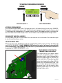
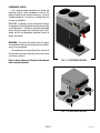
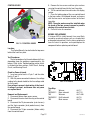
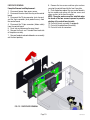
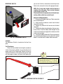
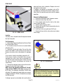
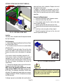
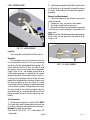
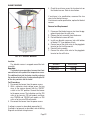
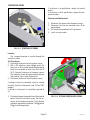
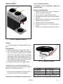
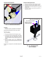
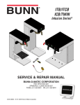
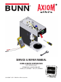
SERVICE & REPAIR MANUAL
BUNN-O-MATIC CORPORATION
POST OFFICE BOX 3227
SPRINGFIELD, ILLINOIS 62708-3227
PHONE: (217) 529-6601 FAX: (217) 529-6644
39132.0000E 04/12 ©2008 Bunn-O-Matic Corporation
BUNN-O-MATIC COMMERCIAL PRODUCT WARRANTY
Bunn-O-Matic Corp. (“BUNN”) warrants equipment manufactured by it as follows:
1) Airpots, thermal carafes, decanters, GPR servers, iced tea/coffee dispensers, MCP/MCA pod brewers thermal
servers and Thermofresh servers (mechanical and digital)- 1 year parts and 1 year labor.
2) All other equipment - 2 years parts and 1 year labor plus added warranties as specified below:
a) Electronic circuit and/or control boards - parts and labor for 3 years.
b) Compressors on refrigeration equipment - 5 years parts and 1 year labor.
c) Grinding burrs on coffee grinding equipment to grind coffee to meet original factory screen sieve analysis
- parts and labor for 4 years or 40,000 pounds of coffee, whichever comes first.
These warranty periods run from the date of installation BUNN warrants that the equipment manufactured by
it will be commercially free of defects in material and workmanship existing at the time of manufacture and appearing within the applicable warranty period. This warranty does not apply to any equipment, component or
part that was not manufactured by BUNN or that, in BUNN’s judgment, has been affected by misuse, neglect,
alteration, improper installation or operation, improper maintenance or repair, non periodic cleaning and descaling, equipment failures related to poor water quality, damage or casualty. In addition, the warranty does not
apply to replacement of items subject to normal use including but not limited to user replaceable parts such as
seals and gaskets. This warranty is conditioned on the Buyer 1) giving BUNN prompt notice of any claim to be
made under this warranty by telephone at (217) 529-6601 or by writing to Post Office Box 3227, Springfield,
Illinois 62708-3227; 2) if requested by BUNN, shipping the defective equipment prepaid to an authorized BUNN
service location; and 3) receiving prior authorization from BUNN that the defective equipment is under warranty.
THE FOREGOING WARRANTY IS EXCLUSIVE AND IS IN LIEU OF ANY OTHER WARRANTY, WRITTEN OR
ORAL, EXPRESS OR IMPLIED, INCLUDING, BUT NOT LIMITED TO, ANY IMPLIED WARRANTY OF EITHER
MERCHANTABILITY OR FITNESS FOR A PARTICULAR PURPOSE. The agents, dealers or employees of BUNN
are not authorized to make modifications to this warranty or to make additional warranties that are binding on
BUNN. Accordingly, statements by such individuals, whether oral or written, do not constitute warranties and
should not be relied upon.
If BUNN determines in its sole discretion that the equipment does not conform to the warranty, BUNN, at its
exclusive option while the equipment is under warranty, shall either 1) provide at no charge replacement parts
and/or labor (during the applicable parts and labor warranty periods specified above) to repair the defective
components, provided that this repair is done by a BUNN Authorized Service Representative; or 2) shall replace
the equipment or refund the purchase price for the equipment.
THE BUYER’S REMEDY AGAINST BUNN FOR THE BREACH OF ANY OBLIGATION ARISING OUT OF THE SALE
OF THIS EQUIPMENT, WHETHER DERIVED FROM WARRANTY OR OTHERWISE, SHALL BE LIMITED, AT
BUNN’S SOLE OPTION AS SPECIFIED HEREIN, TO REPAIR, REPLACEMENT OR REFUND.
In no event shall BUNN be liable for any other damage or loss, including, but not limited to, lost profits, lost
sales, loss of use of equipment, claims of Buyer’s customers, cost of capital, cost of down time, cost of substitute equipment, facilities or services, or any other special, incidental or consequential damages.
392, AutoPOD, AXIOM, BrewLOGIC, BrewMETER, Brew Better Not Bitter, BrewWISE, BrewWIZARD, BUNN
Espress, BUNN Family Gourmet, BUNN Gourmet, BUNN Pour-O-Matic, BUNN, BUNN with the stylized red line,
BUNNlink, Bunn-OMatic, Bunn-O-Matic, BUNNserve, BUNNSERVE with the stylized wrench design, Cool Froth,
DBC, Dr. Brew stylized Dr. design, Dual, Easy Pour, EasyClear, EasyGard, FlavorGard, Gourmet Ice, Gourmet
Juice, High Intensity, iMIX, Infusion Series, Intellisteam, My Café, Phase Brew, PowerLogic, Quality Beverage
Equipment Worldwide, Respect Earth, Respect Earth with the stylized leaf and coffee cherry design, SafetyFresh, savemycoffee.com, Scale-Pro, Silver Series, Single, Smart Funnel, Smart Hopper, SmartWAVE, Soft Heat,
SplashGard, The Mark of Quality in Beverage Equipment Worldwide, ThermoFresh, Titan, trifecta, Velocity Brew,
A Partner You Can Count On, Air Brew, Air Infusion, Beverage Bar Creator, Beverage Profit Calculator, Brew
better, not bitter., BUNNSource, Coffee At Its Best, Cyclonic Heating System, Daypart, Digital Brewer Control,
Nothing Brews Like a BUNN, Pouring Profits, Signature Series, Tea At Its Best, The Horizontal Red Line, Ultra
are either trademarks or registered trademarks of Bunn-O-Matic Corporation.
Page 2
39132 030912
INTRODUCTION
This equipment will brew a half-gallon batch of coffee into an awaiting dispenser. It can be easily configured for
120V 15 amp, 120/208V 20 amp or 120/240V 20 amp. The brewer may have a hot water faucet for allied beverage use.
It is only for indoor use on a sturdy counter or shelf.
CONTENTS
Troubleshooting ..................................................................................................4
Diagnostics .........................................................................................................9
Technician Programming Reminders ................................................................10
Access ..............................................................................................................11
Control Board....................................................................................................12
Face Plate ..........................................................................................................13
Membrane Switch .............................................................................................13
Brew Valve ........................................................................................................14
Optional Brew Valve ..........................................................................................15
Level Probes .....................................................................................................16
Early Refill Valve ...............................................................................................17
Later Refill Valve ...............................................................................................18
Tank Heaters .....................................................................................................20
Limit Thermostat...............................................................................................21
Thermal Cut Off.................................................................................................21
Blanket Warmer ................................................................................................22
Temperature Probe............................................................................................23
Warmer Elements..............................................................................................24
Voltage Selector Switch ....................................................................................25
Power Switch ....................................................................................................26
Programming Level 3........................................................................................27
Programming Level 4........................................................................................29
Wiring Diagrams .............................................................................................. 30
Schematics .......................................................................................................34
Page 3
39132 062309
TROUBLESHOOTING
A troubleshooting guide is provided to suggest probable causes and remedies for the most likely problems
encountered. If the problem remains after exhausting the troubleshooting steps, contact the Bunn-O-Matic
Technical Service Department.
•
•
•
•
•
•
•
Inspection, testing, and repair of electrical equipment should be performed only by qualified service personnel.
All electronic components have ac line voltage and some have low voltage dc potential on their terminals.
Shorting of terminals or the application of external voltages may result in board failure.
Intermittent operation of electronic circuit boards is unlikely. Board failure will normally be permanent. If
an intermittent condition is encountered, the cause will likely be a switch contact or a loose connection at a
terminal or crimp.
Solenoid removal requires interrupting the water supply to the valve. Damage may result if solenoids are
energized for more than ten minutes without a supply of water.
The use of two wrenches is recommended whenever plumbing fittings are tightened or loosened. This will
help to avoid twists and kinks in the tubing.
Make certain that all plumbing connections are sealed and electrical connections tight and isolated.
This brewer is heated at all times. Keep away from combustibles.
WARNING
• Exercise extreme caution when servicing electrical equipment.
• Unplug the brewer when servicing, except when electrical tests are specified.
• Follow recommended service procedures.
• Replace all protective shields or safety notices.
Before assuming a faulty control board, check for the following:
Control Boards
1. Make sure ribbon cable is properly attached to the control board (ALL PINS INSERTED INTO PLUG).
2. Make sure there is a nylon insulating washer under each screw head that holds the control board to the
plastic front end cap. This is important for proper operation.
3. Make sure, before servicing brewer that voltage is present at control board.
4. Press any warmer switch (if equipped) or observe if any indicator lights are glowing on the control panel.
If so, proceed with testing. If not, check for voltage across pins 1 & 2 of the ten pin J1 connector (black and
white wires). If voltage is present, replace the control board. If voltage is not present, check wiring and voltage
across terminal block (black and white on 120 & 120/240 models, or black and red on A models). Correct the
problem and retest before proceeding with testing.
Page 4
39132 062309
TROUBLESHOOTING (cont.)
REFILL CIRCUIT
PROBLEM
PROBABLE CAUSE
REMEDY
Will not refill
1. Power off to brewer
Press OFF/ON switch on control
panel to determine if power is ON.
2. Water shut off
Make sure water is ON.
3. Error Message
Brewer has shut down due to malfunction (See Diagnostic Section in
this manual).
4.ON/OFF Switch
(If equipped)
Make sure ON/OFF Switch is "ON"
and indicator is lit.
5. Lime build up on Probe(s)
Remove the Level Probe(s) and
check for lime deposit on tip. Clean
and reinstall.
6. Refill Valve or Control Board
Refer to page 19
1. Lime build up on probe
Remove Level Probe and check
for lime deposits on tip. Clean and
reinstall.
2. Water Level Sensing System
Replace control board
Refill does not shut off
Power "ON"
3. Refill valve or control board
Check valve. Page 19
1. Refill valve
Clean or replace valve as needed.
Page 19
Refill does not shut off
Power "OFF"
Page 5
39132 080409
TROUBLESHOOTING (cont.)
HEATING CIRCUIT
PROBLEM
PROBABLE CAUSE
REMEDY
Water does not heat to proper
temperature
1. Display's error message
Brewer has shut down due to malfunction. See Diagnostics.
2. Water not touching main (short)
level probe
Remove level probe and grommet.
Look into hole on tank lid. Water
must be within approximately one
inch from top of tank.
3. Water Level Probe Sensing
System
Check refill circuit. Heaters will not
turn on if water is not grounding
level probe.
4. Temperature Probe
Check/replace
5. Limit Thermostat or TCO
Check/replace
6. Tank Heater
Check/replace
1. Lime build up on temperature
probe, tank or tank heater
Inspect probe and tank assembly
for excessive lime deposits. Delime
as required.
2. Temperature Probe
Check/replace
3. Control Board
Check/replace
1. Plumbing lines
Plumbing lines should not rest on
the counter top.
2. Water supply
The brewer must be connected to
a cold water supply.
3. Lime build up
Remove the tank lid and clean inside of tank with a deliming agent,
if necessary.
IMPORTANT: Make sure no temperature tests are taken before
the display reads ready. Tank temperature must be stabilized before
readings are taken.
Spitting or excessive steaming
(cont.)
Brewer is making unusual noises
Page 6
39132 041708
TROUBLESHOOTING (cont.)
BREWING CIRCUIT
PROBLEM
Brew cycle will not start
PROBABLE CAUSE
1. Display's error message
REMEDY
Brewer has shut down due to malfunction. See Diagnostics.
2. No water
Water lines and valves to the brewer
must be open.
3. No power or incorrect voltage to
the brewer
Check for voltage across the terminals at the terminal block.
4. ON/OFF switch not in the "ON"
position
The indicator lamp must be lit
5. Low water temperature (Brew
lockout is enabled)
Allow brewer to heat until ready, or
disable the brew lockout feature.
6. Water not touching refill probe
inside tank
Water must be in contact with refill
probe before brew cycle will start.
Check/replace
7. Membrane Switch
Check/replace
8. Dispense valve
Check/replace
9. Control board
Consistently low beverage level in
the dispenser or beverage overflows
dispenser
1. Brew volume
NOTE: Volume adjustments must be
made with sprayhead installed.
2. Lime build up
Inspect the dispense valve and
sprayhead for excessive lime deposits. Delime as required.
Remove dispense valve and clear
any obstructions. Rebuild or replace
valve if necessary. (See page 24)
Check/replace
3. Dispense Valve
Delime as required.
1. Level probes shorted
Brew cycle starts, then aborts and
returns to Main screen after 20
seconds (SB 153)
Ensure mylar shield(s) are installed
on top cover
Instruct operator to use one procedure but not both
2. On pour over models, the operator poured in water and pressed the
start button
Page 7
39132 061809
TROUBLESHOOTING (cont.)
BREWING CIRCUIT (cont.)
PROBLEM
PROBABLE CAUSE
REMEDY
Dripping from sprayhead
1. Lime build up
Inspect the tank assembly for
excessive lime deposits. Delime
as required.
2. Dispense valve
Check/replace
1. Sprayhead
A clean sprayhead must be used
for proper extraction.
2. Water temperature
Place an empty brew funnel
on an empty decanter beneath
the sprayhead. Initiate brew
cycle and check the water temperature immediately below the
sprayhead with a thermometer.
The reading must not be less
than 195°F (91°C). Adjust the
temperature setting to increase
the water temperature. Refer to
Initial Set-up instructions.
3. Filter type
BUNN® paper filters must be
used for proper extraction.
4. Coffee grind
A fine drip or grind must be used
for proper extraction.
5. Funnel loading
The BUNN® paper filter must
be centered in the funnel and
the bed of grounds leveled by
shaking gently.
1. Sprayhead
Make sure sprayhead is present and holes are clear and
unobstructed.
2. Funnel loading
The BUNN® paper filter must
be centered in the funnel and
the bed of grounds leveled by
shaking gently.
1. Warmer
Check/replace
2. Thermal server/AirPot not
preheated before brew cycle
Preheat server
Weak beverage
Dry coffee grounds remain in
the funnel
Low beverage serving temperature
Page 8
39132 041708
DIAGNOSTICS
MESSAGE
PROBABLE CAUSE
REMEDY
"CHECK SPRAYHEAD FOR LIME" "CHECK FITTINGS FOR LIME"
1. Lime buildup in sprayhead
Clean sprayhead
2. Lime buildup in brew valve
Clean valve
3. Lime buildup in brew tank
Clean tank
1. Lime buildup in sprayhead
Clean sprayhead
2. Lime buildup in brew valve
Clean valve
3. Lime buildup in brew tank
Clean tank
1. Lime buildup in sprayhead
Clean sprayhead
2. Lime buildup in brew valve
Clean valve
3. Lime buildup in brew tank
Clean tank
1. Water temperature in the tank
does not meet the ready temperature.
A) Wait for the brewer to heat to
the proper temperature.
"WARNING INACCURATE FLOW"
- "TOO MUCH LIME PLEASE REPAIR"
"WARNING VERY LOW FLOW" "PLEASE REPAIR"
Temperature Too Low
B) Disable the BREW LOCKOUT
function. Refer to programming
section for procedure.
Heating Time Too Long
1. Tank Heater failure.
Replace or repair as needed
2. Control Board/Thermistor failure
Replace or repair as needed
1. Water shut off to brewer
Check water supply shut-off
2. Supply line too small or obstructed
Replace or repair as needed
3. Inlet Solenoid failure
Replace or repair as needed
4. Control Board Failure
Replace or repair as needed
5. ON/OFF switch is OFF
Turn switch ON
Temp Sensor Out Of Range, Check
For Bad Connections
1. Temperature Sensor Probe
open
Replace or repair as needed
Temp Sensor Out Of Range, Check
Wire For Shorts
1. Temperature Sensor Probe
wire(s) shorted
Page 9
Replace or repair as needed
Fill Time Too Long
39132 041708
TECHNICIAN PROGRAMMING REMINDERS
REVERSE
FORWARD
AXIOM
VERSION
VIEW ASSET/SERIAL #
##.##
ENTER PROGRAMMING
ACCESSING PROGRAM MODES
Press and hold the right hidden switch. The longer you press it, the higher the level you can access. EXAMPLE:
Pressing for a couple seconds enters Level 1. Continuing to press for approximately 5 seconds will access Level
2. Continue pressing for approximately 15 seconds to access Level 3. During program modes, use the right hidden switch to advance forward through screens. Use left hidden switch to step backwards through screens.
VIEWING ASSET AND SERIAL NUMBERS
Press left hidden switch to view Asset number. Press and release to view serial number. Press and release again
to view the installed software version.
FACTORY BLOWOUT MODE
When in the main screen, DO NOT press both left and right hidden switches at the same time. The display will
read "FACTORY BLOWOUT" "ON/OFF". WARNING: NEVER activate this mode. It will open the brew and refill
valves simultaneously. THIS IS FOR FACTORY USE ONLY! If you accidentally enter this screen, exit out of it
by pressing the "ENABLE BREW ON/OFF" switch.
PROGRAMMING LOCKOUT SWITCH
(Mounted on main control board)
This switch can be set to prevent access
to Level 2. Turn "OFF" the switch to access
Technician (Level 2). Once all the correct brew
settings are programmed, the Technician can
set the switch to the "ON" position to prohibit
anyone from changing the settings. With the
switch in the "ON" position, only Level 1 can
be accessed by store personnel. Technicians
can access Level 1 with the switch in either
position. To enter Levels 2, 3, & 4, press and
hold right hidden switch.
Page 10
39132 062309
COMPONENT ACCESS
This section provides procedures for testing and
replacing various major components used in this
brewer should service become necessary. Refer to
Troubleshooting for assistance in determining the
cause of any problem.
WARNING - Inspection, testing, and repair of electrical equipment should be performed only by qualified
service personnel. The brewer should be unplugged
when servicing, except when electrical tests are required and the test procedure specifically states to
plug in the brewer.
WARNING - Disconnect the brewer from the power
source before the removal of any panel or the replacement of any component.
All components are accessible by the removal of
the top cover or warmer housing, front access panel
and warmer plate(s).
Refer to wiring diagrams at the back of this manual
when reconnecting wires.
FIG. 11-1 COMPONENT ACCESS
FIG. 11-2 COMPONENT ACCESS
Page 11
39132 062309
5. Remove the two screws and two nylon washers
securing the control board to the front face plate.
6. Tilt the control board inward to clear the display
section.
7. Place the bottom edge of the new control board
in the two cradles, tilt the board forward, and secure
with the two screws and nylon washers to the front
face plate.
NOTE: The nylon washers must be installed under
the heads of the two screws to prevent a possible
shorting of the control board circuits.
8. Re-install wires & connectors.
CONTROL BOARD
BEFORE REPLACEMENT:
If a triac or MOV is visibly burned, it was most likely
caused by an external sources such as a shorted wire
or damaged solenoid coil. Use the triac map below to
trace the circuit in question, and repair/replace the
component before replacing control board.
FIG. 12-1 CONTROL BOARD
Location:
The Control Board is located inside the top cover
behind the front face plate.
Test Procedures:
The test procedures for the control board will vary
depending upon the problems experienced by the
brewer. Refer to the Troubleshooting section which
is divided into three sections, Refill Circuit, Heating
Circuit, and Brewing Circuit.
Removal and Replacement:
1. Disconnect brewer from power source.
2. Disconnect the wires from the relay on the control
board.
3. Disconnect the 10-pin connector (main harness)
and the 3-pin connector (level probe harness) from
the control board.
4. Disconnect the 10-pin connector (ribbon cable)
from the control board.
Page 12
MOV2
MOV1
Check for Power to board:
1. Insert one meter lead in J1-pin 1 and the other
lead in J1-pin 2.
2. With the power connected to brewer, the voltage
reading to the board should be the line voltage rated
for that model.
If no voltage is present, check wiring to the board.
If voltage is present, and brewer does not power
on, replace board.
TH5
TH4
TH3
TH2
TH1
FIG. 12-2 TRIACS
Triac Map:
TH1
TH2/MOV-1
TH3
TH4/MOV-2
TH5
Warmer
Brew solenoid
Warmers
Refill solenoid
Main warmer
@ J1-7
@ J1-10
@ J1-4&8
@ J1-5
@ J1-6
39132 041708
FACEPLATE REMOVAL
Faceplate Removal and Replacement:
1. Disconnect brewer from power source.
2. Disconnect the wires from the relay on the control
board.
3. Disconnect the 10-pin connector (main harness)
and the 3-pin connector (level probe harness) from
the control board.
4. Disconnect the 10-pin connector (ribbon cable)
from the control board.
5. Drain tank and disconnect/remove faucet.
6. Remove the 3 nuts and 1 standoff from back side
of faceplate assembly.
7. Remove faceplate and control board as an assembly
out the front opening.
8. Remove the two screws and two nylon washers
securing the control board to the front face plate.
9. Place the bottom edge of the new control board in
the two cradles and secure with the two screws and
nylon washers to the front face plate.
NOTE: The nylon washers must be installed under
the heads of the two screws to prevent a possible
shorting of the control board circuits.
10. Re-install faucet assembly (if equipped).
11. Re-install faceplate/board assembly.
12. Re-install wires & connectors.
FIG. 13-1 FACEPLATE REMOVAL
Page 13
39132 061809
you can test it with an ohmmeter or continuity tester.
Refer to the schematic to trace the appropriate pins.
MEMBRANE SWITCH
NOTE: Pin 1 is the static shield & will not provide a
reading to the other pins. There are two commons
in this circuit, pins 9 & 10.
Disconnect brewer from power source before disconnecting ribbon cable from control board.
FIG. 14-1 MEMBRANE SWITCH
Removal and Replacement:
1. Disconnect the ribbon cable from 10-pin connector
on the control board.
2. Gently peel the membrane switch from the front
face plate assembly.
4 Remove any adhesive that remains on the front
face plate.
5. Remove the adhesive backing from the new membrane switch. Insert the ribbon cable through the slot
in the front face plate and apply the membrane switch
to the front face plate.
6. Connect the ribbon cable to the 10-pin connector on
the control board making sure every pin on the control
board is inserted into the ribbon cable connector.
Location:
The Membrane Switch is located on the front face
plate.
Test Procedures:
There are two methods for testing the membrane
switch. The easiest method is to use the built in test
mode. Refer to the Programing Section for Service
Tools/Test Switches. If for some reason you can't get
into the program modes, or brewer won't power up,
Helpful
Hint
Wrap a thin paper clip around each meter lead
and extend past the tip by ¼" - ½". You may
need to sand off the clear coating on some clips!
FIG. 14-2 MEMBRANE SWITCH CONTINUITY
Page 14
39132 100609
BREW VALVE
observed, brew valve is defective. Replace valve and
test again to verify repair.
If voltage is not present as described, refer to Wiring Diagrams and check the brewer wiring harness.
Also check the control board and switch for proper
operation.
Removal and Replacement:
1. Disconnect the brewer from the power source.
2. Disconnect wires from the valve.
3. Drain enough water from the tank so the water
level is below the outlet.
4. Remove hoses from the valve.
5. Remove the two #8-32 nuts securing the valve to
the sprayhead panel.
6. Install new valve using the two #8-32 nuts.
7. Reconnect hoses to the valve and secure in place
with clamps.
FIG. 15-1 BREW VALVE
Location:
The brew valve is located inside the top cover behind
the front face plate.
Test Procedures:
1. Refer to the Programing Section for Service Tools/
Test Outputs/Brew Valve.
2. Be sure brew funnel & server are in place before
activating valve.
3. Check the valve for coil action. Turn on the valve
with the test mode. Listen carefully in the vicinity of
the brew valve for a click as the coil pulls the plunger
in.
If no sound is heard as described, proceed to #4.
If the sound is heard as described, there may be a
blockage in the valve , hose, tank, or sprayhead. Disconnect the brewer from the power source. Remove
the valve and inspect for blockage, and de-lime all
related areas.
4. Connect the voltmeter leads to the coil terminals.
Turn on the valve with the test mode.
NOTE: Due to the internally rectified coil, the indication will be 120VAC all the time. Set the meter
to DC volts. The indication should be 170VDC when
activated. If the polarity of meter leads are reversed,
reading will indicate -170VDC. (Double these readings
for 240 volt coils)
FIG. 15-2 BREW VALVE
Due to the internally rectified coil, do not attempt to
test this type of coil with an ohmmeter. The reading
will be open or very high resistance, depending
on the polarity of your meter leads.
If voltage is present as described, but no coil action is
Page 15
39132 041708
OPTIONAL BREW VALVE (ON SELECT MODELS)
observed, brew valve is defective. Replace valve and
test again to verify repair.
If voltage is not present as described, refer to Wiring Diagrams and check the brewer wiring harness.
Also check the control board and switch for proper
operation.
Removal and Replacement:
1. Disconnect the brewer from the power source.
2. Disconnect wires from the valve.
3. Drain enough water from the tank so the water
level is below the outlet.
4. Remove sprayhead and hose from the valve.
5. Remove the nut securing the valve to the sprayhead
panel.
6. Install new valve using the nut from step 5.
7. Reinstall sprayhead and hose to the valve and
secure in place with clamps.
FIG. 16-1 OPTIONAL BREW VALVE
Location:
The brew valve is located inside the top cover behind
the front face plate.
Test Procedures:
1. Refer to the Programing Section for Service Tools/
Test Outputs/Brew Valve.
2. Be sure brew funnel & server are in place before
activating valve.
3. Check the valve for coil action. Turn on the valve
with the test mode. Listen carefully in the vicinity of
the brew valve for a click as the coil pulls the plunger
in.
If no sound is heard as described, proceed to #4.
If the sound is heard as described, there may be a
blockage in the valve , hose, tank, or sprayhead. Disconnect the brewer from the power source. Remove
the valve and inspect for blockage, and de-lime all
related areas.
4. Connect the voltmeter leads to the coil terminals.
Turn on the valve with the test mode.
NOTE: Due to the internally rectified coil, the indication will be 120VAC all the time. Set the meter
to DC volts. The indication should be 170VDC when
activated. If the polarity of meter leads are reversed,
reading will indicate -170VDC. (Double these readings
for 240 volt coils)
FIG. 16-2 OPTIONAL BREW VALVE
Due to the internally rectified coil, do not attempt to
test this type of coil with an ohmmeter. The reading
will be open or very high resistance, depending on
the polarity of your meter leads.
If voltage is present as described, but no coil action is
Page 16
39132 041708
LEVEL PROBE SYSTEM
2. A high reading (approximately 255) indicates water
is not touching, or not conductive enough to ground
the circuit. A low reading (0-2) indicates the probe is
grounded.
Removal and Replacement:
1. Disconnect the brewer from the power source and
allow tank to cool.
2. Remove nut, wire, and washers from probe.
3. Pull probe straight up from grommet.
4. When reinstalling, ensure long probe is connected
to the blue wire, and short probe is connected to the
brown wire.
NOTE: Heavy mineral build up on probes could indicate
that the tank, lid, and grommets may need to be de
limed as well.
FIG. 17-1 LEVEL PROBES
Location:
The level probes are located inside the tank lid.
Operation:
The level probes sense the water level in the tank
by the conductive minerals in the water grounding
out the very low AC voltage applied to the probes. The
circuit monitors the time it takes the water to drop
the distance from the short probe to the long probe.
Proper "initial set up", and keeping mineral build up
off the probes/grommets, is required for this system
to operate properly. A brew abort feature is "built in".
In the event that the drop in water level from the short
probe to the long probe takes too long, the brew cycle
will abort and return to the main screen. This could
be caused by: Mineral build up on probes/grommets
(very hard water); probes shorting to top cover (verify
the mylar shield(s) are installed; plugged outlet (ie:
sprayhead limed up); incorrect operator use with the
pour over model (ie: pour in water and pressing "start"
button)
Test Procedures:
1. Enter programming level 2, scroll to "Refill". NOTE:
This screen only reads the long probe (blue wire) and
is used for setting the refill conductance threshold.
Alternate: Scroll to "Service Tools".
Then scroll to "LP1 & LP2". LP1 = short probe, LP2
= long probe.
Page 17
FIG. 17-2 LEVEL PROBES
39132 061809
If the sound is not heard as described, proceed to
# 5.
5. Disconnect the brewer from the power source.
6. Check for continuity across the refill valve coil
terminals.
If continuity is not present as described, replace
the refill valve.
If continuity is present as described, there could be
some debris in the valve.
REFILL VALVE - EARLY MODELS
FIG. 18-1 REFILL VALVE
Location:
The refill valve is located inside the front of the
brewer.
Test Procedures:
1. Enter programming level 2, scroll to "Service Tools"
then scroll to "Refill Valve".
2. Briefly activate the refill valve in the test mode.
With a voltmeter, check the voltage across the coil
wires.
3. The indication must be 120 volts ac for two wire 120
volt models and three wire 120/208 -240 volt models
or 230 volts ac for two wire 230 volt models.
If voltage is present, proceed to # 4.
If voltage is not present, refer to Wiring Diagrams
and check main wiring harness. If harness checks
ok, replace control board.
4. Check the refill valve for coil action. Briefly activate
the refill valve in the test mode and listen carefully near
the refill valve for a"clicking" sound as the magnetic
coil pulls the plunger in.
If the sound is heard as described and water will
not pass through the refill valve, there may be a
blockage in the water line before the refill valve or,
the solenoid valve may require inspection for wear,
and removal of waterborne particles.
Page 18
Removal and Replacement:
1. Remove both wires from the refill valve.
2. Verify that the white shutoff clamp between valve
and tank is squeezed shut.
3. Disconnect both water lines at the valve.
4. Remove the two 1/4"-20 screws securing the valve
to the component mounting bracket.
5. Using the two 1/4"-20 screws, install the new valve
to the component mounting bracket.
6. Securely fasten the water lines to the valve.
7. Refer to wiring diagrams when reconnecting the
wires.
8. Install access panels and covers and refer to Initial
Set-up for refill and operation.
FIG. 18-2 REFILL VALVE
39132 041708
REFILL VALVE - LATER MODELS
FIG. 19-1 LATER REFILL VALVE
# 5.
5. Disconnect the brewer from the power source.
6. Check for continuity across the refill valve coil
terminals.
If continuity is not present as described, replace
the refill valve.
If continuity is present as described, there could be
some debris in the valve.
Removal and Replacement:
1. Remove both wires from the refill valve.
2. Verify that the white shutoff clamp between valve
and tank is squeezed shut.
3. Disconnect both water lines at the valve.
4. Remove the two 1/4"-20 screws securing the valve
to the component mounting bracket.
5. Using the two 1/4"-20 screws, install the new valve
to the component mounting bracket.
6. Securely fasten the water lines to the valve.
7. Refer to wiring diagrams when reconnecting the
wires.
8. Install access panels and covers and refer to Initial
Set-up for refill and operation.
Location:
The refill valve is located inside the front of the
brewer.
Test Procedures:
1. Enter programming level 2, scroll to "Service Tools"
then scroll to "Refill Valve".
2. Briefly activate the refill valve in the test mode.
With a voltmeter, check the voltage across the coil
wires.
3. The indication must be 120 volts ac for two wire 120
volt models and three wire 120/208 -240 volt models
or 230 volts ac for two wire 230 volt models.
If voltage is present, proceed to # 4.
If voltage is not present, refer to Wiring Diagrams
and check main wiring harness. If harness checks
ok, replace control board.
4. Check the refill valve for coil action. Briefly activate
the refill valve in the test mode and listen carefully near
the refill valve for a "clicking" sound as the magnetic
coil pulls the plunger in.
If the sound is heard as described and water will
not pass through the refill valve, there may be a
blockage in the water line before the refill valve or,
the solenoid valve may require inspection for wear,
and removal of waterborne particles.
If the sound is not heard as described, proceed to
Page 19
Flow Control Body
Flow Control Washer
Strainer
FIG. 19-2 LATER REFILL VALVE
39132 061809
TANK HEATERS
Location:
The tank heaters are located inside the tank and secured
to the tank bottom.
Test Procedures:
1. With a voltmeter, check voltage across the white
wire (120V Models) or red wire (120/208-240V
Models) from the terminal block and black wire
from the control board. Connect brewer to the
power source. The indication must be 120 volts
ac for two wire 120 volt models or 208-240 volts
ac for three wire 120/208-240 volt models (during
a heating cycle).
2. Disconnect the brewer from the power source.
If voltage is present as described, proceed to #3.
If voltage is not present as described, refer to the
Wiring Diagrams and check wiring harness. If harness
checks ok, replace control board.
3. Disconnect the wires from the tank heater terminals.
4. Check resistance value across tank heater terminals
and compare to chart.
If resistance is present as described, reconnect the
wires, the tank heater is ok.
If resistance is not present as described, replace the
tank heater.
NOTE- If any resistance is read between sheath and
either terminal, remove and inspect heater for cracks
in the sheath.
HEATER
RESISTANCE
1425W-120V
10.10
3500W-240V
16.46
1850W-240V
31.14
3500W-200V
11.43
3000W-240V
19.20
2268W-240V
6.35
TERMINAL TO SHEATH - INFINITE (OPEN)
Page 20
2268W
Large
Dia.
1425W
Small
Dia.
FIG. 20-1 DV TANK HEATERS
Removal and Replacement:
1. Remove the top cover or top warmer housing and
front access panel as previously described.
2. Drain water from the tank.
3. Disconnect all the hoses from the tank.
4. Disconnect the temperature probe from the top of
the tank by pulling the probe from the grommet in
the top of the tank lid.
5. Remove both level probes from their grommets.
6. Disconnect the green wire from the top of the
tank.
7. Disconnect the limit thermostat from the side of
the tank.
8. Disconnect the two white wires from the tank
warmer blanket.
9. Disconnect the wires from tank heater terminals.
10. Remove the four #8-32 nuts securing the tank to
the mounting brackets and remove the tank assembly.
11. Remove the eight #8-32 nuts securing the tank lid
to the tank.
12. Remove the two hex nuts securing the tank heater
to the bottom of the tank. Remove tank heater with
gaskets and discard.
13. Install new tank heater(s) with gaskets to the bottom of the tank and secure with two hex nuts.
14. Install tank assembly onto mounting brackets and
secure in place with four #8-32 nuts.
15. Install tank lid and secure in place with eight #8-32
nuts.
16. Connect the two white wires of the tank warmer
blanket.
39132 041708
LIMIT THERMOSTAT
THERMAL CUT OFF (230V MODELS ONLY)
FIG. 21-1 TCO CHECK
Location:
The TCO's are located under the tank at the heater
connections.
FIG. 21-2 LIMIT THERMOSTAT
Location:
The limit thermostat is located inside the top cover on
the front side of the tank.
Test Procedures:
1. Disconnect the brewer from the power source.
2. Disconnect the wires from the limit thermostat.
3. With an ohmmeter, check for continuity across
the limit thermostat terminals.
Test Procedures:
1. Disconnect the brewer from the power source.
2. Disconnect the TCO from the tank heater.
3. With an ohmmeter, check for continuity across
the TCO as shown above.
If continuity is not present as described, replace the
main harness.
If continuity is present as described, the limit thermostat
is operating properly.
If continuity is not present as described, replace the
limit thermostat.
Removal and Replacement:
1. Remove the wires from limit thermostat terminals.
2. Carefully slide the limit thermostat out from under
the retaining clip and remove limit thermostat.
3. Carefully slide the new limit thermostat into the
retaining clip. Ensure the metal face has good contact
with tank.
Page 21
39132 041708
BLANKET WARMER
4. Check the resistance across the two terminals on
the blanket warmer. Refer to chart below.
If resistance is to specification, reconnect the two
wires to the blanket warmer.
If resistance is not to specification, replace the blanket
warmer.
Removal and Replacement:
1. Disconnect the blanket warmer wire from the piggyback terminal on the refill valve.
2. Remove the tank assembly from the brewer.
3. Peel old blanket warmer off tank.
4. Install new blanket warmer on tank with bottom
of blanket 1½˝ from bottom of tank.
5. Connect one of the white wires to the piggyback
terminal on the limit thermostat.
6. Reinstall tank assembly.
7. Connect the other white wire to the piggyback
terminal on the refill valve.
FIG. 22-1 BLANKET WARMER
Location:
The blanket warmer is wrapped around the tank
assembly.
Operation:
The blanket warmer provides a low consistent heat
around the tank at the point of the temperature sensor.
This additional heat aids the heater circuit by reducing
the number of on/off cycles, thereby extending the life
of the relay contacts and the heater.
WARMER
50W-120V
50W-220V
RESISTANCE
288.0
968.0
Test Procedures:
1. Disconnect the brewer from the power source.
2. With a voltmeter, check voltage across the two
wires at the warmer element with the "ON/OFF"
switch in the "ON" position. Connect the brewer
to the power source. The indication must be 120
volts ac for two wire 120 volt models and three
wire 120/208 and 120/240 volt models, or 230
volts ac for two wire 230 volt models.
3. Disconnect the brewer from the power source.
If voltage is present as described, proceed to #4.
If voltage is not present as described, refer to Wiring
Diagrams and check wiring harness.
Page 22
39132 041708
TEMPERATURE PROBE
If resistance is to specification, replace the control
board.
If resistance is not to specification, replace the temperature probe.
Removal and Replacement:
1. Disconnect the brewer from the power source.
2. Disconnect the two pin connector from J9 on
control board.
3. Pull temperature probe out of it's grommet.
4. Install in reverse order.
FIG. 23-1 TEMPERATURE PROBE
Location:
The temperature probe is inserted through the
tank lid assembly.
Test Procedures:
1. Disconnect the brewer from the power source.
2. With a DC voltmeter, check voltage across the
two wires at J9 on control board (Black probe to
black wire, red probe to white wire. Refer to FIG
18-2). Connect the brewer to the power source.
The indication should be approximately between
4vdc cool to 1vdc at ready temperature.
3. Disconnect the brewer from the power source.
If voltage is present as described, circuit is working
correctly, check limit thermostat (and TCO on 230V
models).
If voltage is not present as described, proceed to
#4.
4. Disconnect temperature probe from J9 on control
board. Check the resistance across the two terminals of the temperature probe. The indication
should be approximately between 10.5K cool to
870 at ready temperature.
Page 23
FIG. 23-2 TESTING TEMPERATURE PROBE
39132 041708
WARMER ELEMENTS
wires to the warmer element.
If resistance is not to specification, replace the
warmer element.
Removal and Replacement:
1. Remove the three #4-40 screws securing the
warmer assembly to the brewer.
2. Lift the warmer assembly from the brewer.
3. Disconnect the two wires from the warmer element
terminals.
4. Remove the two #8-32 nuts securing the warmer
element to the warmer plate.
5. Securely install new warmer element.
6. Reconnect the two wires to warmer element terminals.
7. Securely install warmer assembly on the brewer.
FIG. 24-1 WARMER ELEMENTS
Location:
The warmer element(s) is located under the warmer
plate.
Test Procedures:
1. Disconnect the brewer from the power source.
2. With a voltmeter, check voltage across the two
wires at the warmer element with the "ON/OFF"
switch in the "ON" position. Connect the brewer
to the power source. The indication must be 120
volts ac for two wire 120 volt models and three
wire 120/208 and 120/240 volt models, or 230
volts ac for two wire 230 volt models.
3. Disconnect the brewer from the power source.
If voltage is present as described, proceed to #4.
If voltage is not present as described, refer to Wiring
Diagrams and check wiring harness.
4. Check the resistance across the two terminals on
the warmer element. Refer to chart below.
FIG. 24-2 WARMER ELEMENTS
WARMER
RESISTANCE
100W-120V
144.0
100W-220V
484.0
100W-200V
400.0
TERMINAL TO SHEATH - INFINITE (OPEN)
If resistance is to specification, reconnect the two
Page 24
39132 041708
VOLTAGE SELECTOR SWITCH
Removal and Replacement:
1. Disconnect the brewer from the power source.
2. Disconnect the wires from the power switch.
3. Remove the switch mounting screws from the left
side of trunk.
4. Install new switch in trunk with the two 6-32 x ¼˝
mounting screws.
White to Term. Block-120V Position
Blue to Tank Heater-Common
WHI/VIO to Tank Heater
120/208-240V Position
FIG. 25-1 VOLTAGE SELECTOR SWITCH
Location:
The power switch is located on the component
mounting bracket behind the front access panel.
Test Procedure:
1. Disconnect the brewer from the power source.
2. Disconnect the wires from the selector switch. With
the selector switch in the 120V position, check for
continuity between the two right terminals of the
switch.
3. With the selector switch in the 120/208-240V
position, check for continuity between the two left
terminals.
If continuity is not present as described, replace the
switch.
FIG. 25-2 VOLTAGE SELECTOR
SWITCH TERMINALS
Page 25
39132 041708
MASTER ON/OFF SWITCH
Removal and Replacement:
1. Disconnect the brewer from the power source.
2. Disconnect the wires from the power switch.
3. Remove the switch mounting screws from the left
side of trunk.
4. Install new switch in trunk with the two 6-32 x ¼˝
mounting screws.
FIG. 26-1 MASTER ON/OFF SWITCH
Location:
The rocker switch is located on the left side of
the trunk behind the front access panel on some
earlier models. The toggle switch on later models is
located on the back of the trunk.
Test Procedure:
FIG. 26-2 TOGGLE SWITCH LOCATION
1. Disconnect the brewer from the power source.
2. Disconnect the wires from the power switch. With
the switch in the ON position, check for continuity
between the upper and lower terminals on each
side of the switch.
There should be continuity between the two left terminals and between the two right terminals when ON,
no continuity when OFF.
If continuity is not present as described, replace the
switch.
L2
L1
FIG. 26-3 ROCKER SWITCH
Page 26
39132 052410
PROGRAMMING FUNCTIONS LEVEL 3 - FLOW CHART
ENTERING LEVEL 3
REVERSE
FORWARD
AXIOM
VERSION
CAL TEMPERATURE
%
NO SENSOR? YES
(-)
SPRAY OZ/M:
(-)
DONE
##.#
(+)
##.##
LimeAdjust
DONE
OFF
(+)
CALIBRATE FLOW ?
NO
Page 27
YES
LP1 LP2 OZ 4.50
(-)
DONE
(+)
AXIOM
VERSION
##.##
39132 062309
PROGRAMMING - LEVEL 3
CAL TEMPERATURE
NO SENSOR? YES
Allows technician to calibrate after probe and/or control board replacement. Select "YES".
NOTE: Tank temperature must be within range (192° - 208° F)
VIDEO CLIP: Calibrate Temp Click - >
200°
CAL
200°
(-)
DONE
(+)
%
(-)
LimeAdjust
DONE
OFF
(+)
LP1 LP2 OZ 4.50
(-)
DONE
SPRAY OZ/M:
(-)
DONE
This screen allows adjustment of the lime compensation system when
BrewLOGIC is turned on.
Range: 2 - 50. Default: 10% variation of brewed volume.
The remaining screens in Level 3 are just a convenient shortcut to the
same ones used in previous levels.
(+)
##.#
(+)
CALIBRATE FLOW ?
NO
Insert an accurate thermometer approximately 10˝ into tank. Adjust the
number on the right with +/- until it matches reading of thermometer.
Select "DONE"
YES
VIDEO CLIP: Calibrate sprayhead flow
rate with BrewLogic on Click - >
VIDEO CLIP: Calibrate sprayhead flow
rate with BrewLogic off Click - >
Page 28
39132 032012
PROGRAMMING FUNCTIONS LEVEL 4 - FLOW CHART
ENTERING LEVEL 4
REVERSE
FORWARD
AXIOM
VERSION
SERIAL # TYPE
(-)
AX00
AX00
(+)
(+)
AX00000000
(-)
DONE
AXIOM
AX00000000
SERIAL # TYPE
(-)
##.##
(+)
(-)
DONE
(+)
VERSION
##.##
In case of board replacement, match the Data Plate information.
AX00 - Standard Axiom with warmers
AXAP - Axiom AirPot Server
AXTN - Not used
AXTS - Axiom Thermal Server
EP00 - Engineering Prototype
Scroll down (-) or up (+), to set the serial number of the machine.
NOTE: Starting from the right, each digit will control the next digit,
like an odometer.
Page 29
39132 062309
Page 30
39132 041708
ALL MODELS EXCEPT TWINS
0/6 TWIN
Page 31
39132 041708
4/2 TWIN
Page 32
39132 041708
TWIN APS
Page 33
39132 041708
MAIN ON/OFF SWITCH
(Late 20 & 35
Models only)
BLK-14
BLK Model 20 & 35
LIMIT
THERMOSTAT
BLU-14
BLK-14
WHI-14 Model 20
RED-14 Model 35
TANK HEATER
BLK-14
N
L2
RED Model 35
WHI Model 20
WHI Model 15 & 35
BLK
L1
WHI Model 20
BLK Model 15
SCHEMATIC WIRING DIAGRAM
GREEN
AXIOM
WHI Model 15
"KEEP WARM" HEATER
WHI
WHI
BREW STATION WARMER
WHI/RED (CONTROLLED BY ON/OFF SW)
BLK
WHI
REFILL
WHI/BLU
DISPENSE
#
/
.
4
2
/
,
0
#
"
/
!
2
$
RELAY
BLU-14
BLK-14
J1-1
WHI
BLK
J1-5
J1-10
WHI/GRN
WHI
SOL
WHI
BRN/BLK
VIO
P2
BRN/BLK FRONT WARMER
P3
REAR WARMER
VIO
(NOTE – ALL WARMERS ARE NOT
AVAILABLE ON ALL MODELS!)
YEL
P2
YEL
P3
WHI/VIO
B1
A6
D1
A3
D2
A4
D3
A5
B2
A2
WHI/VIO
FRONT WARMER
REAR WARMER
J9-1
W
H
I
WHI
P1
WHI
P1, P2, &
P3 ARE
PINS OF A
POLARIZED
THREE-PIN
CONNECTOR.
P1
WHI
W
H
I
A1
CONTROL SWITCH ASSY CODES
J2-10
J3-3
WHI
(LEFT WARMER)
CONTROL SWITCH ASSY
STATIC
SHIELD
J2-6
J3-1
WHI
(TOP OR RIGHT WARMERS)
BRN/BLK
WHI/BLU
WHI/RED
YEL
WHI/VIO
VIO
WHI/GRN
J2-1
SOL
BREW STATION
LEFT FRONT
LEFT REAR
TOP FRONT
TOP REAR
RIGHT FRONT
RIGHT REAR
START BREW
LEFT HIDDEN
RIGHT HIDDEN
“DIGITAL”
“BREWER”
“CONTROL”
BRN
GRN
BLU
WHI
BLK
LEVEL PROBE
(SHORT)
to
LEVEL PROBE
(LONG)
2 WARMERS 2 WARMERS 2 WARMERS
ON LEFT
ON TOP
ON RIGHT
A3
A3
A3
A2
A1
A5
A6
A5
A6
A4
A4
A4
B1
B1
B1
B2
B2
B2
D1
D1
D1
D2
D2
D2
D3
D3
D3
OPTIONAL DUAL TOP WARMER ASSY
WHI
3
BLK
BLK 2
1 BRN/BLK
WHI
REAR
WHI
120V AC 2 WIRE
120/208V AC 3 WIRE
120/240V AC 3 WIRE
SINGLE PHASE
3
BLK 2
1 BLU/BLK
WHI
FRONT
29077.0006D 02/09 ©2006 BUNN-O-MATIC CORPORATION
Page 34
39132 052709
Page 35
39132 041708
GRN
N
L2
WHI
BLK
L1
RED
SCHEMATIC WIRING DIAGRAM
AXIOM DV
MAIN ON/OFF SWITCH
(Late Models only)
BLK
BLK-14
SELECTOR
SWITCH
LIMIT
THERMOSTAT
BLU-14
BLK-14
TANK HEATER
BLK-14
WHI-14
BLU-14
WHI
TANK HEATER
WHI/VIO-14
1425W
"KEEP WARM" HEATER
RED-14
2268W
WHI
BREW STATION WARMER
(CONTROLLED
BY ON/OFF SW)
WHI/RED
WHI
REFILL
WHI/BLU
DISPENSE
#
/
.
4
2
/
,
0
#
"
/
!
2
$
RELAY
BLU-14
BLK-14
J1-1
WHI
BLK
J1-5
J1-10
WHI/GRN
WHI
WHI
SOL
WHI
(TOP OR RIGHT WARMERS)
BRN/BLK
BRN/BLK
WHI/BLU
WHI/RED
YEL
WHI/VIO
VIO
WHI/GRN
VIO
P2
BRN/BLK FRONT WARMER
P3
REAR WARMER
VIO
WHI
W
H
I
(LEFT WARMER)
CONTROL SWITCH ASSY
STATIC
SHIELD
J2-1
SOL
(NOTE – ALL WARMERS ARE NOT
AVAILABLE ON ALL MODELS!)
YEL
P2
P3
WHI/VIO
FRONT WARMER
YEL
WHI/VIO
REAR WARMER
WHI
P1
P1, P2, &
P3 ARE
PINS OF A
POLARIZED
THREE-PIN
CONNECTOR.
P1
WHI
WHI
W
H
I
J2-6
B1
A6
D1
A3
D2
A4
D3
A5
B2
A2
A1
J2-10
CONTROL SWITCH ASSY CODES
J3-1
J3-3
J9-1
BRN
GRN
BLU
WHI
BLK
LEVEL PROBE (SHORT)
120V AC 2 WIRE + GND
120/208V AC 3 WIRE + GND
120/240V AC 3 WIRE + GND
SINGLE PHASE
LEVEL PROBE (LONG)
to
29077.0008B
BREW STATION
LEFT FRONT
LEFT REAR
TOP FRONT
TOP REAR
RIGHT FRONT
RIGHT REAR
START BREW
LEFT HIDDEN
RIGHT HIDDEN
“DIGITAL”
“BREWER”
“CONTROL”
2 WARMERS 2 WARMERS 2 WARMERS
ON LEFT
ON TOP
ON RIGHT
A3
A3
A3
A2
A1
A5
A6
A5
A6
A4
A4
A4
B1
B1
B1
B2
B2
B2
D1
D1
D1
D2
D2
D2
D3
D3
D3
01/07 ©2006 BUNN-O-MATIC CORPORATION
Page 36
39132 041708
29077.0012 obsolete, refer to 29077.0022
Page 37
39132 071111
Page 38
39132 041708
"
/
!
2
$
#
/
.
4
2
/
,
0
#
J9
J3
J2
J1
1
2
3
1
10
5
1
10
5
1
COM
N.O.
TRM 1
TRM 2
BLK-18
BLK-14
WHI
BLK
BRN
GRN
BLU
B1
A6
STATIC
SHIELD
WHI/GRN
BLU-14
WHI/GRN
D1
A3
D2
#
/
.
4
2
/
,
0
!
A1
.
%
,
A4
to
D3
A5
B2
REAR
FRONT
HI
W
WHI
WHI
J9
J3
J2
J1
1
2
3
1
10
5
1
10
5
1
COM
N.O.
TRM 1
TRM 2
WHI
BLK
BRN
GRN
BLU
B1
A6
STATIC
SHIELD
VIO
WHI/GRN
BLU-14
D1
A3
D2
A4
to
D3
A5
B2
A2
(NOTE – ALL WARMERS ARE NOT
AVAILABLE ON ALL MODELS!)
#
/
.
4
2
/
,
0
!
A1
.
%
,
WHI/RED
REFILL SOL
BRN/BLK
"KEEP WARM" HEATER
W
HI
WHI
WHI
WHI
WHI
WHI
WHI
(RIGHT SIDE WARMERS)
REAR
O K
V I /B L
N
BR
FRONT
VIO
BREW STATION WARMER
WHI/BLU
DISPENSE SOL
TANK HEATER
WHI/GRN
BLK-14
CONTROL SWITCH ASSY
COUNTER
(OPTIONAL)
BRN/BLK
WHI/BLU
WHI/RED
WHI
BLK
BLU-14
BLK-14
BLK
BLK
WHI
LIMIT
THERMOSTAT
BREW STATION
LEFT FRONT
LEFT REAR
TOP FRONT
TOP REAR
RIGHT FRONT
RIGHT REAR
START BREW
LEFT HIDDEN
RIGHT HIDDEN
“DIGITAL”
“BREWER”
“CONTROL”
CONTROL SWITCH ASSY CODES
2 WARMERS 2 WARMERS 2 WARMERS
ON LEFT
ON TOP
ON RIGHT
A3
A3
A3
A2
A1
A5
A6
A5
A6
A4
A4
A4
B1
B1
B1
B2
B2
B2
D1
D1
D1
D2
D2
D2
D3
D3
D3
LEVEL PROBE (LONG)
"
/
!
2
$
#
/
.
4
2
/
,
0
#
BLK-18
BLK-14
RED-14
WHI-14
Chassis Ground
GRN
Earth Ground
LEVEL PROBE (LONG)
N
LEVEL PROBE (SHORT)
29077.0014C 02/08 ©2007 BUNN-O-MATIC CORPORATION
(LEFT SIDE WARMERS)
/V
W EL
Y
YEL
WHI/VIO
WHI
WHI
WHI
WHI
WHI-14
BLK-14
BLK-18
MAIN ON/OFF SWITCH
(Late Models only)
L2
L1
BLK
LEVEL PROBE (SHORT)
A2
(NOTE – ALL WARMERS ARE NOT
AVAILABLE ON ALL MODELS!)
REFILL SOL
"KEEP WARM" HEATER
RED-14
BREW STATION WARMER
WHI/BLU
DISPENSE SOL
BLK-14 TANK HEATER
CONTROL SWITCH ASSY
COUNTER
(OPTIONAL)
WHI/BLU
RED/BLK
YEL
WHI/VIO
WHI
BLK
BLU-14
BLK-14
BLK
BLK
WHI
LIMIT
THERMOSTAT
120/208V AC 3 WIRE + GND
120/240V AC 3 WIRE + GND
SINGLE PHASE
SCHEMATIC WIRING DIAGRAM AXIOM TWIN 0/6
RED
Page 39
39132 041708
"
/
!
2
$
#
/
.
4
2
/
,
0
#
J9
J3
J2
J1
1
2
3
1
10
5
1
10
5
1
COM
N.O.
TRM 1
TRM 2
BLK-18
BLK-14
WHI
BLK
BRN
GRN
BLU
B1
STATIC
SHIELD
WHI/GRN
BLU-14
D1
A3
D2
A4
to
D3
A5
B2
(NOTE – ALL WARMERS ARE NOT
AVAILABLE ON ALL MODELS!)
SOL
RIGHT
LEFT
P3 P2 P1
!
P1, P2, &
P3 ARE
PINS OF A
POLARIZED
THREE-PIN
CONNECTOR
J9
J3
J2
J1
1
2
3
1
10
5
1
10
5
1
COM
N.O.
TRM 1
TRM 2
WHI
BLK
BRN
GRN
BLU
B1
STATIC
SHIELD
WHI/GRN
BLU-14
BLK-14
D1
A3
D2
A4
to
D3
A5
B2
#
/
.
4
2
/
,
0
!
.
%
,
WHI/RED
WHI/GRN
TANK HEATER
(NOTE – ALL WARMERS ARE NOT
AVAILABLE ON ALL MODELS!)
CONTROL SWITCH ASSY
COUNTER
(OPTIONAL)
WHI/YEL
WHI/BLU
WHI/RED
WHI
BLK
BLU-14
BLK-14
BLK
BLK
WHI
LIMIT
THERMOSTAT
BREW STATION
LEFT FRONT
LEFT REAR
TOP FRONT
TOP REAR
RIGHT FRONT
RIGHT REAR
START BREW
LEFT HIDDEN
RIGHT HIDDEN
“DIGITAL”
“BREWER”
“CONTROL”
CONTROL SWITCH ASSY CODES
SOL
REFILL
BREW STATION WARMER
SOL
WHI/BLU
BREW
!
"KEEP WARM" HEATER
2 WARMERS 2 WARMERS 2 WARMERS
ON LEFT
ON TOP
ON RIGHT
A3
A3
A3
A2
A1
A5
A6
A5
A6
A4
A4
A4
B1
B1
B1
B2
B2
B2
D1
D1
D1
D2
D2
D2
D3
D3
D3
LEVEL PROBE (LONG)
"
/
!
2
$
#
/
.
4
2
/
,
0
#
BLK-18
BLK-14
RED-14
WHI-14
Chassis Ground
GRN
Earth Ground
LEVEL PROBE (SHORT)
N
LEVEL PROBE (LONG)
29077.0015A 06/08 ©2008 BUNN-O-MATIC CORPORATION
WHI
WHI
WHI
WHI
WHI
WHI
(TOP WARMERS)
BREW STATION WARMER
SOL
BREW
WHI/BLU
REFILL
"KEEP WARM" HEATER
RED-14
WHI-14
BLK-14
BLK-18
MAIN ON/OFF SWITCH
(Late Models only)
L2
L1
BLK
LEVEL PROBE (SHORT)
#
/
.
4
2
/
,
0
!
.
%
,
WHI/GRN
BLK-14 TANK HEATER
CONTROL SWITCH ASSY
COUNTER
(OPTIONAL)
YEL
WHI/BLU
RED/BLK
WHI
BLK
BLU-14
BLK-14
BLK
BLK
WHI
LIMIT
THERMOSTAT
120/208V AC 3 WIRE + GND
120/240V AC 3 WIRE + GND
SINGLE PHASE
SCHEMATIC WIRING DIAGRAM AXIOM TWIN 2/2
RED
WHI
WHI
WHI
WHI
WHI
SCHEMATIC WIRING DIAGRAM AXIOM-APS
N
L1
GRN
GRN/YEL
Chassis Ground
Chassis Ground
Earth Ground
RED
BLK
EMI
FILTER
BLK
WHI
MAIN POWER
SWITCH
LIMIT
THERMOSTAT
BLU-14
BLK-14
TANK HEATER
BLK-14
WHI-14
"KEEP WARM" HEATER
WHI
WHI
REFILL
BLK
WHI/BLU
DISPENSE
#
/
.
4
2
/
,
0
#
"
/
!
2
$
RELAY
BLU-14
BLK-14
J1-1
WHI
BLK
J1-5
J1-10
WHI/GRN
SOL
WHI
WHI
SOL
WHI
BRN/BLK
WHI/BLU
WHI/RED
YEL
WHI/VIO
VIO
WHI/GRN
CONTROL SWITCH ASSY
STATIC
SHIELD
J2-1
J2-6
B1
D1
A3
D2
A4
D3
B2
J2-10
CONTROL SWITCH ASSY CODES
J3-1
J3-3
J9-1
BRN
GRN
BLU
WHI
BLK
LEVEL PROBE (SHORT)
LEVEL PROBE (LONG)
to
100V AC
2 WIRE
SINGLE PHASE
BREW STATION
LEFT FRONT
LEFT REAR
TOP FRONT
TOP REAR
RIGHT FRONT
RIGHT REAR
START BREW
LEFT HIDDEN
RIGHT HIDDEN
“DIGITAL”
“BREWER”
“CONTROL”
2 WARMERS 2 WARMERS 2 WARMERS
ON LEFT
ON TOP
ON RIGHT
A3
A3
A3
A2
A1
A5
A6
A5
A6
A4
A4
A4
B1
B1
B1
B2
B2
B2
D1
D1
D1
D2
D2
D2
D3
D3
D3
29077.0016B 11/09 ©2008 BUNN-O-MATIC CORPORATION
Page 40
39132 120309
SCHEMATIC WIRING DIAGRAM AXIOM-APS
L1
L2
GRN/YEL
RED
BLK
EMI
FILTER
WHI
BLK
LIMIT
THERMAL
FUSE
BLU-14
BLK-14
BLK-14
THERMOSTAT
TANK HEATER
THERMAL
FUSE
WHI-14
"KEEP WARM" HEATER
WHI
WHI
WHI
BLK
REFILL
WHI/BLU
DISPENSE
#
/
.
4
2
/
,
0
#
"
/
!
2
$
RELAY
BLU-14
BLK-14
J1-1
WHI
BLK
J1-5
J1-10
WHI/GRN
SOL
WHI
WHI
SOL
WHI
BRN/BLK
WHI/BLU
WHI/RED
YEL
WHI/VIO
VIO
WHI/GRN
CONTROL SWITCH ASSY
STATIC
SHIELD
J2-1
J2-6
B1
D1
A3
D2
A4
D3
B2
J2-10
CONTROL SWITCH ASSY CODES
J3-1
J3-3
J9-1
BRN
GRN
BLU
WHI
BLK
LEVEL PROBE (SHORT)
LEVEL PROBE (LONG)
to
230 VOLTS CE
2 WIRE + GND
SINGLE PHASE
50 HZ
BREW STATION
LEFT FRONT
LEFT REAR
TOP FRONT
TOP REAR
RIGHT FRONT
RIGHT REAR
START BREW
LEFT HIDDEN
RIGHT HIDDEN
“DIGITAL”
“BREWER”
“CONTROL”
2 WARMERS 2 WARMERS 2 WARMERS
ON LEFT
ON TOP
ON RIGHT
A3
A3
A3
A2
A1
A5
A6
A5
A6
A4
A4
A4
B1
B1
B1
B2
B2
B2
D1
D1
D1
D2
D2
D2
D3
D3
D3
29077.0017A 10/08 ©2008 BUNN-O-MATIC CORPORATION
Page 41
39132 041708
GRN
WHI
BLK
SCHEMATIC WIRING DIAGRAM
AXIOM DV-APS/TC
N
L2
RED
L1
Earth Ground
MAIN ON/OFF SWITCH
(Late Models only)
Chassis Ground
BLK
BLK-14
SELECTOR
SWITCH
LIMIT
THERMOSTAT
BLU-14
BLK-14
BLK-14
TANK HEATER
WHI/VIO-14
1425W
"KEEP WARM" HEATER
WHI
WHI-14
BLU-14
TANK HEATER
RED-14
2268W
WHI
REFILL
WHI/BLU
DISPENSE
#
/
.
4
2
/
,
0
#
"
/
!
2
$
RELAY
BLU-14
BLK-14
J1-1
WHI
BLK
J1-5
J1-10
WHI/GRN
SOL
WHI
WHI
SOL
WHI
WHI/BLU
WHI/GRN
CONTROL SWITCH ASSY
STATIC
SHIELD
J2-1
J2-6
B1
D1
A3
D2
A4
D3
B2
J2-10
#
/
.
4
2
/
,
0
!
.
%
,
CONTROL SWITCH ASSY CODES
J3-1
J3-3
J9-1
BRN
GRN
BLU
WHI
BLK
LEVEL PROBE (SHORT)
120V AC 2 WIRE + GND
120/208V AC 3 WIRE + GND
120/240V AC 3 WIRE + GND
SINGLE PHASE
LEVEL PROBE (LONG)
to
BREW STATION
LEFT FRONT
LEFT REAR
TOP FRONT
TOP REAR
RIGHT FRONT
RIGHT REAR
START BREW
LEFT HIDDEN
RIGHT HIDDEN
“DIGITAL”
“BREWER”
“CONTROL”
2 WARMERS 2 WARMERS 2 WARMERS
ON LEFT
ON TOP
ON RIGHT
A3
A3
A3
A2
A1
A5
A6
A5
A6
A4
A4
A4
B1
B1
B1
B2
B2
B2
D1
D1
D1
D2
D2
D2
D3
D3
D3
29077.0018A 11/08 ©2008 BUNN-O-MATIC CORPORATION
Page 42
39132 041708
L1
RED Model 35
WHI Model 20
WHI Model 15 & 35
BLK
MAIN ON/OFF SWITCH
(Late 20 & 35
Models only)
BLK-14
BLK Model 20 & 35
LIMIT
THERMOSTAT
BLU-14
BLK-14
TANK HEATER
BLK-14
N
L2
WHI-14 Model 20
RED-14 Model 35
WHI Model 20
BLK Model 15
SCHEMATIC WIRING DIAGRAM
SINGLE AXIOM - 15, 20 & 35 GREEN
WHI Model 15
"KEEP WARM" HEATER
WHI
WHI
BREW STATION WARMER
WHI/RED (CONTROLLED BY ENABLE BREW SW)
REFILL
BLK
WHI/BLU
DISPENSE
#
/
.
4
2
/
,
0
#
"
/
!
2
$
RELAY
BLU-14
BLK-14
J1-1
WHI
BLK
J1-5
WHI/BLU
WHI/RED
J1-10
WHI/GRN
WHI
WHI
SOL
WHI
SOL
WHI
WHI/GRN
CONTROL SWITCH ASSY
STATIC
SHIELD
J2-1
(NOTE – ALL WARMERS ARE NOT
AVAILABLE ON ALL MODELS!)
J2-6
B1
A6
D1
A3
D2
A4
D3
A5
B2
J2-10
CONTROL SWITCH ASSY CODES
J3-1
J3-3
J9-1
BRN
GRN
BLU
WHI
BLK
LEVEL PROBE
(SHORT)
to
120V AC 2 WIRE
120/208V AC 3 WIRE
120/240V AC 3 WIRE
SINGLE PHASE
29077.0019A
BREW WARMER
HALF
FULL
START BREW
LEFT HIDDEN
RIGHT HIDDEN
“DIGITAL”
“BREWER”
“CONTROL”
A3
A5
A6
A4
B1
B2
D1
D2
D3
LEVEL PROBE
(LONG)
03/09 ©2009 BUNN-O-MATIC CORPORATION
Page 43
39132 041708
6&+(0$7,&:,5,1*',$*5$0$;,20
L1
L2
GRN/YEL
RED
BLK
EMI
FILTER
WHI
BLK
LIMIT
THERMAL
FUSE
BLU-14
BLK-14
TANK HEATER
BLK-14
THERMOSTAT
THERMAL
FUSE
WHI-14
"KEEP WARM" HEATER
WHI
WHI
BREW STATION WARMER
WHI/RED (CONTROLLED BY ON/OFF SW)
BLK
WHI
WHI
REFILL
WHI/BLU
DISPENSE
#
/
.
4
2
/
,
0
#
"
/
!
2
$
RELAY
BLU-14
BLK-14
J1-1
WHI
BLK
J1-5
J1-10
WHI/GRN
WHI
WHI
SOL
WHI
(TOP OR RIGHT WARMERS)
BRN/BLK
BRN/BLK
WHI/BLU
WHI/RED
YEL
WHI/VIO
VIO
WHI/GRN
VIO
P2
P3
BRN/BLK FRONT WARMER
VIO
REAR WARMER
WHI
:
+
,
(LEFT WARMER)
CONTROL SWITCH ASSY
STATIC
SHIELD
J2-1
SOL
(NOTE – ALL WARMERS ARE NOT
AVAILABLE ON ALL MODELS!)
YEL
P2
P3
WHI/VIO
FRONT WARMER
YEL
WHI/VIO
REAR WARMER
WHI
P1
WHI
P1, P2, &
P3 ARE
PINS OF A
POLARIZED
THREE-PIN
CONNECTOR.
P1
WHI
:
+
,
J2-6
B1
A6
D1
A3
D2
A4
D3
A5
B2
A2
A1
J2-10
CONTROL SWITCH ASSY CODES
J3-1
J3-3
J9-1
BRN
GRN
BLU
WHI
BLK
LEVEL PROBE (SHORT)
LEVEL PROBE (LONG)
t°
92/76
:,5(*1'
6,1*/(3+$6(
+=
BREW STATION
LEFT FRONT
LEFT REAR
TOP FRONT
TOP REAR
RIGHT FRONT
RIGHT REAR
START BREW
LEFT HIDDEN
RIGHT HIDDEN
“DIGITAL”
“BREWER”
“CONTROL”
2 WARMERS 2 WARMERS 2 WARMERS
ON LEFT
ON TOP
ON RIGHT
A3
A3
A3
A2
A1
A5
A6
A5
A6
A4
A4
A4
B1
B1
B1
B2
B2
B2
D1
D1
D1
D2
D2
D2
D3
D3
D3
29077.0020B 04/10 ©2009 BUNN-O-MATIC CORPORATION
Page 44
39132 061710
Page 45
39132 061710
0
#
"
/
!
2
$
#
/
.
4
2
/
,
J9
J3
J2
J1
1
2
3
1
10
5
1
10
5
1
COM
N.O.
TRM 1
TRM 2
BLK-18
BLK-14
WHI
BLK
BRN
GRN
BLU
B1
D1
A3
D2
A4
D3
B2
WHI/GRN
t°
WHI/BLU
LEVEL PROBE (LONG)
LEVEL PROBE (SHORT)
#
/
.
4
2
/
,
0
!
.
%
,
SOL
DISPENSE
BLK-14 TANK HEATER
L. Level Harness-p/n 39048.0000
STATIC
SHIELD
WHI/GRN
BLU-14
CONTROL SWITCH ASSY
COUNTER
(OPTIONAL)
WHI/BLU
WHI
BLK
BLU-14
BLK-14
BLK
BLK
WHI
LIMIT
THERMOSTAT
9$&:,5(*1'
9$&:,5(*1'
6,1*/(3+$6(
WHI
WHI
WHI
WHI
Main Harness
p/n 40666.0005
29077.0022A 06/10 ©2010 BUNN-O-MATIC CORPORATION
SOL
REFILL
"KEEP WARM" HEATER
RED-14
WHI-14
BLK-14
BLK-18
MAIN ON/OFF SWITCH
(Late Models only)
Harness, Switch to Term Block
P/N 38920.0002
L2
L1
BLK
N
0
#
"
/
!
2
$
#
/
.
4
2
/
,
J9
J3
J2
J1
1
2
3
1
10
5
1
10
5
1
COM
N.O.
TRM 1
TRM 2
BLK-18
BLK-14
RED-14
WHI-14
BRN
GRN
BLU
B1
D1
A3
D2
A4
D3
B2
t°
LEVEL PROBE (LONG)
LEVEL PROBE (SHORT)
#
/
.
4
2
/
,
0
!
.
%
,
SOL
CONTROL SWITCH ASSY CODES
SOL
REFILL
"KEEP WARM" HEATER
2 WARMERS 2 WARMERS 2 WARMERS
ON LEFT
ON TOP
ON RIGHT
A3
A3
A3
A2
A1
A5
A6
A5
A6
A4
A4
A4
B1
B1
B1
B2
B2
B2
D1
D1
D1
D2
D2
D2
D3
D3
D3
WHI/RED
DISPENSE
TANK HEATER
BREW STATION
LEFT FRONT
LEFT REAR
TOP FRONT
TOP REAR
RIGHT FRONT
RIGHT REAR
START BREW
LEFT HIDDEN
RIGHT HIDDEN
“DIGITAL”
“BREWER”
“CONTROL”
WHI/GRN
BLK-14
CONTROL SWITCH ASSY
BLU-14
L. Level Harness-p/n 39048.0000
STATIC
SHIELD
WHI/GRN
WHI/RED
WHI
BLK
COUNTER
(OPTIONAL)
LIMIT
THERMOSTAT
WHI
BLU-14
BLK-14
BLK
BLK
WHI
BLK
Chassis Ground
GRN
Earth Ground
BREWERS WITH 1 POWER CORD ONLY
6&+(0$7,&:,5,1*',$*5$0$;,207:,1$367&
RED
WHI
WHI
WHI
WHI
SCHEMATIC WIRING DIAGRAM
AXIOM TWIN APS/TC
100-200 VOLTS AC
230 VOLTS AC CE
2 WIRE + GND
SINGLE PHASE 50-60 HZ
L2 or N
CONTROL SWITCH ASSY CODES
Earth Ground
RED
or
WHI
BLK
L1
MAIN ON/OFF SWITCH
OPTIONAL
RED
or
WHI
BLK
GRN or GRN/YEL
Chassis Ground
EMI
FILTER
Chassis Ground
CE ONLY
BLK
BLK
WHI
WHI
LIMIT
THERMOSTAT
LIMIT
THERMOSTAT
BLU-14
WHI
C
O
N
T
R
O
L
J1
P
C
B
O
A
R
D
J2
BLK
BLK
COUNTER
(OPTIONAL)
COM
N.O.
BLU-14
BLK-14
1
WHI
BLK
THERMAL
FUSE
BLK
TRM 1
TRM 2
BLK-14 TANK HEATER
WHI/BLU
10
WHI/GRN
WHI-14
WHI
SOL
C
O
N
T
R
O
L
WHI
DISPENSE
WHI/GRN
SOL
WHI
B1
3
BRN
GRN
BLU
1
2
WHI
BLK
TRM 1
TRM 2
J1
P
C
B
O
A
R
D
CONTROL SWITCH ASSY
J2
D1
A3
D2
A4
D3
10
J9
WHI
BLK
WHI/BLU
STATIC
SHIELD
1
1
WHI
REFILL
5
J3
"KEEP WARM" HEATER
THERMAL
FUSE
WHI
5
BLU-14
BLK-14
B2
C
O
N
T
R
O
L
P
A
N
E
L
BLK
BLK
COUNTER
(OPTIONAL)
COM
N.O.
BLU-14
BLK-14
1
WHI
BLK
5
WHI/RED
10
WHI/GRN
THERMAL
FUSE
BLK-14
2 WARMERS 2 WARMERS 2 WARMERS
ON LEFT
ON TOP
ON RIGHT
A3
A3
A3
A2
A1
A5
A6
A5
A6
A4
A4
A4
B1
B1
B1
B2
B2
B2
D1
D1
D1
D2
D2
D2
D3
D3
D3
BREW STATION
LEFT FRONT
LEFT REAR
TOP FRONT
TOP REAR
RIGHT FRONT
RIGHT REAR
START BREW
LEFT HIDDEN
RIGHT HIDDEN
“DIGITAL”
“BREWER”
“CONTROL”
BLK-14
WHI
SOL
WHI
WHI
DISPENSE
WHI/GRN
SOL
WHI
WHI
CONTROL SWITCH ASSY
B1
D1
A3
D2
A4
D3
10
J9
WHI-14
WHI/RED
STATIC
SHIELD
1
3
BRN
GRN
BLU
1
2
WHI
BLK
1
"KEEP WARM" HEATER
THERMAL
FUSE
REFILL
5
J3
LEVEL PROBE (SHORT)
B2
C
O
N
T
R
O
L
P
A
N
E
L
LEVEL PROBE (SHORT)
LEVEL PROBE (LONG)
t°
TANK HEATER
LEVEL PROBE (LONG)
29077.0023A 11/11 ©2011 BUNN-O-MATIC CORPORATION
Page 46
t°
39132 101310
SCHEMATIC WIRING DIAGRAM AXIOM TS
L1
L2 or N
TERMINAL BLOCK
MAIN ON/OFF SWITCH
GRN/YEL
BLK
BLK
WHI
RED
EMI
FILTER
WHI
BLK
LIMIT
BLU-14
BLK-14
THERMOSTAT
"KEEP WARM" HEATER
WHI
WHI
BLK
C
O
N
T
R
O
L
P
C
B
O
A
R
D
RELAY
BLU-14
BLK-14
J1-1
WHI
BLK
THERMAL
FUSE
BLK-14
THERMAL
FUSE
TANK HEATER
WHI-14
WHI
REFILL
J1-5
WHI/BLU
WHI/BLU
SOL
WHI
DISPENSE
J1-10
WHI/GRN
WHI/GRN
WHI
SOL
CONTROL SWITCH ASSY
STATIC
SHIELD
J2-1
J2-6
D1
B1
A3
D2
A4
D3
A7
B2
A2
A1
J2-10
CONTROL SWITCH ASSY CODES
J3-1
J3-3
BRN
GRN
BLU
J9-1
WHI
BLK
J9-1
RED
BLK
A3
BREW “A”
BREW “B”
BREW “C”
A1
A2
A7
START BREW
LEFT HIDDEN
RIGHT HIDDEN
“DIGITAL”
“BREWER”
“CONTROL”
A4
B1
B2
D1
D2
D3
LEVEL PROBE (SHORT)
+
BEEPER
LEVEL PROBE (LONG)
-
t°
100-200 VOLTS
2 WIRE + GND
SINGLE PHASE
50/60 HZ
ON/OFF
29077.0025A 10/11 ©2011 BUNN-O-MATIC CORPORATION
Page 47
39132 071111
Page 48
39132 021512
"
/
!
2
$
#
/
.
4
2
/
,
0
#
J9
J3
J2
J1
1
2
3
1
10
5
1
10
5
1
COM
N.O.
TRM 1
TRM 2
BLK-18
BLK-14
WHI
BLK
BRN
GRN
BLU
B1
A6
STATIC
SHIELD
WHI/GRN
BLU-14
WHI/GRN
D1
A3
D2
#
/
.
4
2
/
,
0
!
A1
.
%
,
A4
t°
D3
A5
B2
P1, P2, &
P3 ARE
PINS OF A
POLARIZED
THREE-PIN
CONNECTOR
J9
J3
J2
J1
1
2
3
1
10
5
1
10
5
1
COM
N.O.
TRM 1
TRM 2
WHI
BLK
BRN
GRN
BLU
B1
A6
STATIC
SHIELD
VIO
WHI/GRN
BLU-14
D1
A3
D2
A4
t°
D3
A5
B2
A2
(NOTE – ALL WARMERS ARE NOT
AVAILABLE ON ALL MODELS!)
#
/
.
4
2
/
,
0
!
A1
.
%
,
WHI/RED
REFILL SOL
WHI
WHI
WHI
WHI
WHI
WHI
(TOP WARMERS)
REAR
FRONT
P3 P2 P1
"KEEP WARM" HEATER
BREW STATION WARMER
WHI/BLU
DISPENSE SOL
TANK HEATER
WHI/GRN
BLK-14
CONTROL SWITCH ASSY
COUNTER
(OPTIONAL)
BRN/BLK
WHI/BLU
WHI/RED
WHI
BLK
BLU-14
BLK-14
BLK
BLK
WHI
LIMIT
THERMOSTAT
BREW STATION
LEFT FRONT
LEFT REAR
TOP FRONT
TOP REAR
RIGHT FRONT
RIGHT REAR
START BREW
LEFT HIDDEN
RIGHT HIDDEN
“DIGITAL”
“BREWER”
“CONTROL”
CONTROL SWITCH ASSY CODES
2 WARMERS 2 WARMERS 2 WARMERS
ON LEFT
ON TOP
ON RIGHT
A3
A3
A3
A2
A1
A5
A6
A5
A6
A4
A4
A4
B1
B1
B1
B2
B2
B2
D1
D1
D1
D2
D2
D2
D3
D3
D3
LEVEL PROBE (LONG)
"
/
!
2
$
#
/
.
4
2
/
,
0
#
BLK-18
BLK-14
RED-14
WHI-14
Chassis Ground
GRN
Earth Ground
LEVEL PROBE (SHORT)
N
LEVEL PROBE (LONG)
29077.0026A 02/12 ©2012 BUNN-O-MATIC CORPORATION
(TOP WARMERS)
REAR
FRONT
P3 P2 P1
WHI
WHI
WHI
WHI
WHI
WHI
WHI-14
BLK-14
BLK-18
MAIN ON/OFF SWITCH
(Late Models only)
L2
L1
BLK
LEVEL PROBE (SHORT)
A2
(NOTE – ALL WARMERS ARE NOT
AVAILABLE ON ALL MODELS!)
REFILL SOL
"KEEP WARM" HEATER
RED-14
BREW STATION WARMER
WHI/BLU
DISPENSE SOL
BLK-14 TANK HEATER
CONTROL SWITCH ASSY
COUNTER
(OPTIONAL)
WHI/BLU
RED/BLK
YEL
WHI/VIO
WHI
BLK
BLU-14
BLK-14
BLK
BLK
WHI
LIMIT
THERMOSTAT
120/208V AC 3 WIRE + GND
120/240V AC 3 WIRE + GND
SINGLE PHASE
SCHEMATIC WIRING DIAGRAM AXIOM TWIN 4/2
RED
P1, P2, &
P3 ARE
PINS OF A
POLARIZED
THREE-PIN
CONNECTOR