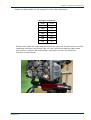
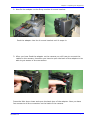
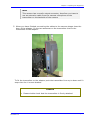
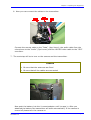
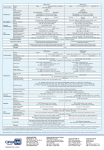
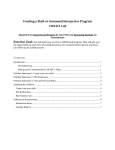
1
REFERENCE GUIDE
CT2020
v.1.3
ENGLISH (UK)
Preposition
ENGLISH (UK)
ITALIANO
Please read this first!
LEGGERE QUESTO AVVISO PER PRIMO!
If you do not understand the contents of this manual:
Do not operate this equipment.
Se non si capisce il contenuto del presente manuale
NON UTILIZZARE L’APPARECCHIATURA.
Also, translation of this manual into any EC official language can be made
available, at your cost.
È anche disponibile la versione italiana di questo manuale, ma il costo è a
carico dell’utente.
SVENSKA
NEDERLANDS
LÄS DETTA FÖRST!
LEES DIT EERST!
Om Ni inte förstår informationen i denna handbok
ARBETA DÅ INTE MED DENNA UTRUSTNING.
Als u de inhoud van deze handleiding niet begrijpt
STEL DEZE APPARATUUR DAN NIET IN WERKING.
En översättning till detta språk av denna handbok kan också
anskaffas, på Er bekostnad.
U kunt tevens, op eigen kosten, een vertaling van deze handleiding
krijgen.
PORTUGUÊS
SUOMI
LEIA O TEXTO ABAIXO ANTES DE MAIS NADA!
LUE ENNEN KÄYTTÖÄ!
Se não compreende o texto deste manual
NÃO UTILIZE O EQUIPAMENTO.
Jos et ymmärrä käsikirjan sisältöä
ÄLÄ KÄYTÄ LAITETTA.
O utilizador poderá também obter uma tradução do manual para o
português à própria custa.
Käsikirja voidaan myös suomentaa asiakkaan kustannuksella.
FRANÇAIS
DANSK
AVANT TOUT, LISEZ CE QUI SUIT!
LÆS DETTE FØRST!
Si vous ne comprenez pas les instructions contenues dans ce
manuel
NE FAITES PAS FONCTIONNER CET APPAREIL.
Udstyret må ikke betjenes
En outre, nous pouvons vous proposer, à vos frais, une version
française de ce manuel.
MEDMINDRE DE TIL FULDE FORSTÅR INDHOLDET AF
DENNE HÅNDBOG.
Vi kan også for Deres regning levere en dansk oversættelse af
denne håndbog.
DEUTSCH
LESEN SIE ZUERST DIESEN HINWEIS!
Sollte Ihnen der Inhalt dieses Handbuches nicht klar verständlich
sein, dann
Bedienen Sie dieses Gerät nicht.
Eine Übersetzung des Handbuches in dieser Sprache ist gegen
Berechnung lieferbar.
ESPAÑOL
LEA ESTE AVISO PRIMERO!
Si no entiende el contenido de este manual
NO OPERE ESTE EQUIPO.
Podemos asimismo suministrarle una traducción de este manual
al (idioma) previo pago de una cantidad adicional que deberá
abonar usted mismo.
Reference Guide: CT2020
November 10
Page ii
Preposition
List of Contents
Chapter 1: Introduction to the CT2020
Gives a general description of the equipment, main features and functions.
Identifies the controls, indicators and connectors on the front and rear
panels.
Chapter 2: Installing the Equipment
Provides a guide to the suitability of an installation and gives detailed
procedures for the preparation and installation of the equipment. Also
details the external connectors and provides important safety
information.
Chapter 3: Operating the Equipment Locally
Describes local control in detail. Provides the power-up/power-down
procedures and other general operating/control/set-up procedures.
Chapter 4: Application note for wireless HD Camera’s
Describes the mounting of the CT2020HD on the Sony 1500 Camera
Annex A: List of Abbreviations
Annex B: Technical Specification
Reference Guide: CT2020
November 10
Page iii
Preposition
Contents
Preposition
List of Contents ........................................................................................ ii
About this Reference Guide ........................................................................vi
Nomenclature...........................................................................................vi
Acknowledgements .................................................................................. vii
General............................................................................................... vii
Registered Trademarks ......................................................................... vii
Trademarks ......................................................................................... vii
Warnings, Cautions and Notes .................................................................. viii
Heed Warnings ................................................................................... viii
Read Instructions ................................................................................ viii
Follow Instructions .............................................................................. viii
Retain Instructions .............................................................................. viii
EMC Compliance ..................................................................................... viii
Contact Information ..................................................................................ix
BMS-Europe Customer Services...............................................................ix
Technical Training ................................................................................. x
Customer Services and Technical Training Postal Address............................ x
Return of Equipment .............................................................................. x
Technical Publications ............................................................................ x
Chapters 1 to 4
1. Introduction to the CT2020HD................................................................10
1.1 Preliminary Remarks .......................................................................10
1.2 Designation and P/N........................................................................10
1.3 Description ....................................................................................11
2. Installing the Equipment .......................................................................12
2.1 Safety instructions ..........................................................................12
2.2 Connectors ....................................................................................13
2.3 Shut-Down.....................................................................................14
3. Operating the Equipment.......................................................................15
3.1 Multifunctional display .....................................................................15
3.2 Menu structure ...............................................................................16
3.3 Frequency input (1).........................................................................17
3.4 Resolution (3) ................................................................................17
3.5 Framerate (4).................................................................................18
3.6 Modulation (5)................................................................................19
3.7 Latency (6) ....................................................................................20
3.8 Audio Select (7)..............................................................................21
Reference Guide: CT2020
November 10
Page iv
Preposition
3.9 Audio L /R Input (8 and 9) ...............................................................22
3.10 Aud L/R Gain (10 and 11)...............................................................23
3.11 Mic Phantom (12 and 13) ...............................................................23
3.12 Data Freq (14) (optional) ...............................................................25
3.13 Output Power (15) ........................................................................26
3.14 Contrast (16)................................................................................26
3.15 Display OFF (17) ...........................................................................27
3.16 Software (18) ...............................................................................27
3.17 Status* (19).................................................................................28
3.18 Encoder FW* (20) .........................................................................28
4. APPLICATION NOTE FOR WIRELESS HD CAMERAS
30
4.1 Introduction.......................................................................................30
4.2 Mounting instructions for CT2020HD on the Sony 1500 camera.................31
Appendix A
List of Abbreviations
Appendix B
Technical Specification
B.1… Compliance .................................................................................. B-1
B.1.1 Safety ................................................................................... B-1
B.1.2 EMC ...................................................................................... B-1
B.1.3 Shock and Vibration ................................................................ B-2
B.1.4 CE Marking ............................................................................. B-2
B.1.5 FCC Marking ............................................................................ B-2
B.2
Technical Specifications ................................................................... B-4
Reference Guide: CT2020
November 10
Page v
Preposition
About this Reference Guide
This Reference Guide provides instructions and information for the
installation and operation of the CT2020.
This Reference Guide should be kept in a safe place for reference for the
life of the equipment. It is not intended that this Reference Guide will be
amended by the issue of individual pages. Any revision will be by a
complete reissue. Further copies of this Reference Guide can be ordered
from the address shown on page ix. If passing the equipment to a third
party, also pass the relevant documentation.
Issues of this Reference Guide are listed below:
Issue
Date
Build Version
Comments
1
March 2008
1.0
Initial release.
2
August 2008
1.1
New chapters integrated
3
March
1.2
Changes CT2020HD to CT2020
4
November 2010
1.3
Changes in Menu Structure
Note…
The Build Version in the table refers to an overall number which
encompasses all the various software/firmware versions of video,
audio, etc in the device.
Reference Guide: CT2020
November 10
Page vi
Preposition
Acknowledgements
General
All best endeavors have been made to acknowledge registered trademarks
and trademarks used throughout this Reference Guide. Any notified
omissions will be rectified in the next issue of this Reference Guide. Some
trademarks may be registered in some countries but not in others.
Registered trademarks and trademarks used are acknowledged below and
marked with their respective symbols. However, they are not marked
within the text of this Reference Guide.
Registered Trademarks
AC-3®, Dolby Digital® and Pro Logic® are registered trademarks of Dolby
Laboratories Licensing Corporation.
Musicam® is a registered trademark of Thomson and Télédiffusion de
France (TDF), Europe, and is a registered trademark of CCS (now Musicam
USA Incorporated), USA.
Ethernet® is a registered trademark of Xerox Corporation.
XILINX® is a registered trademark of Xilinx Inc.
Reference Guide: CT2020
November 10
Page vii
Preposition
Warnings, Cautions and Notes
Heed Warnings
All warnings on the product and in the operating instructions should be
adhered to. The manufacturer can not be held responsible for injuries or
damage where warnings and cautions have been ignored or taken lightly.
Read Instructions
All the safety and operating instructions should be read before this product
is operated.
Follow Instructions
All operating and use instructions should be followed.
Retain Instructions
The safety and operating instructions should be retained for future
reference.
Warnings…
Warnings give information which, if strictly observed, will
prevent personal injury or death, OR DAMAGE TO PERSONAL
PROPERTY OR THE ENVIRONMENT. They are boxed and
shaded for emphasis, as in this example, and are placed
immediately preceding the point at which the reader
requires them.
Cautions...
Cautions give information which, if strictly followed, will prevent
damage to equipment or other goods. They are boxed for emphasis,
as in this example, and are placed immediately preceding the point
at which the reader requires them.
Notes...
Notes provide supplementary information. They are highlighted for
emphasis, as in this example, and are placed immediately after
the relevant text.
EMC Compliance
This equipment is certified to the EMC requirements detailed in Annex B,
Technical Specification. To maintain this certification, only use the leads
supplied or if in doubt contact Customer Services.
Reference Guide: CT2020
November 10
Page viii
Preposition
RF Exposure Info:
For body worn operation, device has been tested and meets FCC RF
exposure guidelines when used with an accessory that contains no metal
and that positions device a minimum of 20cm from the body. Use of other
accessories may not ensure compliance with FCC RF exposure guidelines.
Technical Training
Training Courses
BMS Europe provides a wide range of training courses on the operation
and maintenance of our products and on their supporting technologies.
BMS can provide both regularly scheduled courses and training tailored to
individual needs. Courses can be run either at your premises or at one of
our dedicated training facilities.
Where to Find Us
For further information on BMS Europe training program please
contact us:
International Telephone:
International Facsimile
+ 49 6124 7239-00
+ 49 6124 7239-29
Customer Services and BMS Europe Postal Address
BMS-Europe GmbH
Schwalbacher Straße 12
65321 Heidenrod – Kemel
Germany
Return of Equipment
If you need to return equipment for repair, please contact
Tel:
+ 49 6124 7239-00
Fax:
+ 49 6124 7239-29
BMS-Europe GmbH
Schwalbacher Straße 12
65321 Heidenrod – Kemel
Germany
Reference Guide: CT2020
November 10
Page ix
Chapter 3: Options and Upgrades
1. Introduction to the CT2020HD
1.1 Preliminary Remarks
This manual is provided for users and operators of the CT2020 Transmitter. It is
intended to support the installation, operation, maintenance and daily use of the unit
in general.
The manual should be kept with the CT2020 Transmitter and may be consulted when
questions occur. Should problems remain after you have read the manual carefully or
if you have any further questions concerning the functionality or operation of the
Transmitter, please contact Customer Service.
1.2 Designation and P/N
Designation
CT2020HD
Frequency range
P/N
2.0 – 2.3 GHz
11.2422.500
2.3 – 2.6 GHz
11.2422.100
other frequencies and models on request
Reference Guide: CT2020
November 10
Page 10
Chapter 3: Options and Upgrades
1.3 Description
General Information on D-ENG (Digital Electronic News Gathering)
The introduction of the DVB standard established the basis for digital broadcast video
transmission making efficient use of the available bandwidth. Powerful compression
algorithms allow a reduction in the amount of data to be transferred, while
maintaining the high quality standards for video and audio signals used in broadcasting applications. New modulation techniques and error correction algorithms
ensure a secure signal transmission even when the transmission conditions are poor.
The DVB-T standard was established for terrestrial digital TV broadcasting, in
particular considering the difficult conditions of radio transmission. The highly efficient
OFDM multicarrier modulation procedure enables transmission without interference
even under multipath propagation conditions occurring with non-directional
transmission or reception. Practical experience soon has proved that the DVB-T
standard guarantees ruggedness of transmission to an extent even allowing mobile
reception.
Increasing miniaturization, in particular of MPEG encoders and OFDM modulators,
enables using the DVB-T standard for mobile portable transmission systems.
Previous analog FM systems were adversely affected by signal reflections directly
resulting in video and audio interferences. Such effects do not occur when the digital
ENG system (D-ENG) is deployed. Even mobile transmission from moving vehicles or
the use of omni-directional antennas on the transmitting or receiving side does not
impair the picture or sound quality at all, opening a completely new range of
applications in TV production and news gathering.
Video Inputs
The CT2020 accepts only HDSDI*(HD version) and SDI information at the input:
•
SDI BNC(f)
OFDM (Orthogonal Frequency Division Multiplex) Modulator
The digital data signal for wireless transmission is processed by the OFDM Modulator
and following IQ Modulator. The OFDM modulation procedure has a major impact on
the transmission properties and was specifically developed for terrestrial radio
transmission.
User interface
The integrated Multifunctional Display allows easy configuration of the device. The
current Software and firmware version can also be displayed.
Linear Power Amplifier
The linear power amplifier amplifies the output signal of the Modulator to an output of
about 400 mW (+26 dBm at 2GHz, depending on frequency). The output port is
located on top of the device.
Reference Guide: CT2020
November 10
Page 11
Chapter 3: Options and Upgrades
2. Installing the Equipment
2.1 Safety instructions
Warning
The regulations of VDE0100 must be observed for
installation and operation of the unit.
Caution
• Establish all other connections before starting the unit by
connecting it to 12VDC. Essential, a valid video signal must be
connected to the desired input before power on the CT2020.
• When you connect the CT2020 as described in the following
sections, make sure that the "Caution" instructions given there
are observed.
• Make sure that there is sufficient air circulation to ensure
adequate cooling of the unit.
External forced ventilation may be required if the unit is installed
in a rack or cabinet.
Reference Guide: CT2020
November 10
Page 12
Chapter 3: Options and Upgrades
2.2 Connectors
Figure 1
Input connector of the CT2020*(HD version)
RF Connector
The RF output signal of the Low-Power Amplifier is fed out at the N(f) connector on
top of the unit.
The CT2020 provides RF output of about 400 mW (+26dBm) at 2GHz band.
Connecting Signal Sources
The Video signal supplied by the camera has to be applied to the SDI BNC(f)
connector of the transmitter.
The analogue Audio signal supplied by the camera has to be applied to the Audio in
5pol Lemo connector of the transmitter.
Connecting the RF Output
An omni directional antenna with N(m) connector can be directly mounted at the RF
out socket.
Connecting the UHF Data Input (optional)
An UHF antenna with SMA(m) connector can be directly mounted at the UHF in
socket.
Reference Guide: CT2020
November 10
Page 13
Chapter 3: Options and Upgrades
Connecting the 12VDC Supply Voltage
Caution
When using a battery or power pack, make sure that the maximum
supply current is at least 3A and the output voltage matches the
input voltage range of the CT2020.
Failure to comply with these requirements may cause fatal
damage to the battery/power pack and/or CT2020.
Battery Powered Operation of the CT2020
Many types of batteries are available on the market and we tried to support the best
ones.
2.3 Shut-Down
Caution
To shut-down the unit you have to disconnect first the 12VDC
supply voltage.
After disconnection from the supply voltage by removing the battery or disconnecting
the 12VDC supply cable, the other connecting cables can be removed from the unit.
Reference Guide: CT2020
November 10
Page 14
Chapter 4: Operating the Equipment
3. Operating the Equipment
3.1 Multifunctional display
During start up the transmitter is in a self test mode. After the self test the
transmitter’s name is displayed before the display permanentlyshows the current
frequency.
UHF Data Receive
Quality
Current transmission frequency
The automatic COFDM setup is very easy to handle.
When the Enter-Button is pressed and held for approximately 2 seconds the setup
menu is accessible:
Reference Guide: CT2020
November 10
Page 15
Chapter 4: Operating the Equipment
3.2 Menu structure
Use Up and Down button to navigate through this menu. To activate a sub menu
press Enter-button for 2 seconds.
To exit all sub menus press Enter button.
Reference Guide: CT2020
November 10
Page 16
Chapter 4: Operating the Equipment
3.3 Frequency input (1)
At the frequency menu the current frequency is displayed.
To change the frequency press Enter button for 2 sec.
The inverted digit displays the current changeable position of the frequency. By use of
Up and Down button the inverted digit can be changed, digit by digit. To confirm a
change and switch to the next position of the frequency press Enter-button and
continue with the next digit. To save the changed frequency and leave this sub-menu
press Enter-button after all digits of the frequency are set.
3.4 Resolution (3)
In the sub menu “Resolution” the desired resolution of your transmitter can be
chosen.
Reference Guide: CT2020
November 10
Page 17
Chapter 4: Operating the Equipment
Four options for resolution are available. For proper selection, please check the video
output of your camera.
•
SD
•
720p (HD version)
•
1080i (HD version)
•
1080p (HD version)
To edit the resolution sub-menu press Enter-Button for 2 seconds.
Use the Up- and Down-Buttons for navigation and select the desired modulation by
pressing the Enter-Button.
To exit this submenu press Enter-Button.
3.5 Framerate (4)
After setting the resolution (1080p/1080i/720p/SD) it is important to set the correct
corresponding frame-rate.
Please check, at all costs, which HD output signal, which resolution the video signal
has and which frame-rate (1080p/1080i/720p) the camera is set to. A list of the
resolution and corresponding frame rates is added below.
The following Frame rates are available:
•
23,98 Hz (1080p) – (only HD verion)
•
24 Hz (1080p) – (only HD verion)
•
24 PsF (1080p) – (only HD verion)
•
50 Hz (1080i/720p/SD)
•
59,94 Hz (1080i/720p/SD)
•
60 Hz (1080i/720p/SD)
Reference Guide: CT2020
November 10
Page 18
Chapter 4: Operating the Equipment
To edit the frame rate sub-menu press Enter-Button for 2 seconds.
Use the Up- and Down-Buttons for navigation and select the desired frame rate by
pressing the Enter-Button.
To exit this submenu press Enter-Button.
Note
With PsF, a progressive frame is sliced into two "segments", with
the odd lines in one segment and the even lines in the other
segment. This allows for a progressive picture to be processed
through the same electronic circuitry that is used to store, process
and route interlaced video. Technically, progressive segments are
equivalent to interlaced fields, but unlike native interlaced video,
there is no motion between the two fields to make up the video
frame, both fields represent the same instant in time.
3.6 Modulation (5)
In the sub menu “Modulation” the Modulation method can be changed. The following
options are available:
•
QPSK (if SD Resolution is selected)
•
16 QAM (if SD Resolution is selected)
•
64 QAM (1080p/1080i/720p/SD)
Below table shows the Bitrates for the different modulation options. FEC and Guard
Interval will be changed automatically along with the selected modulation.
Bitrate for SD Modulations
Modulation
FEC
GUARD
BITRATE
QPSK
½
1/32
6.03 MBit/s
16QAM
½
1/32
12.06 MBit/s
64QAM
½
1/32
18.09 MBit/s
Reference Guide: CT2020
November 10
Page 19
Chapter 4: Operating the Equipment
Bitrate for HD Modulations
Modulation
FEC
GUARD
BITRATE
64QAM
2/3
1/32
24.13 MBit/s
Note
If you have selected the HD resolution 1080p or 1080i or 720p a
modulation of 64QAM will be used and can not be changed.
To edit the modulation sub-menu press Enter-Button for 2 seconds.
Use the Up- and Down-Buttons for navigation and select the desired modulation by
pressing the Enter-Button.
To exit this submenu press Enter-Button.
3.7 Latency (6)
In the sub-menu “Latency” the latency can be chosen. There are two settings,
“Ultra low” and “Standard”.
If low latency is your requirement, then please use the “Ultra-low” setting
If you require a higher picture quality then use the option “Standard”.
Reference Guide: CT2020
November 10
Page 20
Chapter 4: Operating the Equipment
To edit the latency sub-menu press Enter-Button for 2 seconds.
Use the Up- and Down-Buttons for navigation and select the desired latency by
pressing the Enter-Button.
To exit this submenu press Enter-Button.
3.8 Audio Select (7)
In the sub-menu “AUDIO SELECT” the required Audio input can be chosen.
•
EMBED (Embedded)
•
LINE
Please set the transmitter Audio input to match the selected Audio input source. For
example, if you use a microphone or line audio then please chose the option “LINE”. If
Embedded Audio will be used, then “EMBEDDED” must be selected
AUDIO SELECT
EMBED
AUDIO SELECT
LINE
To edit the ”AUDIO SELECT” sub-menu press Enter-Button for 2 seconds.
Use the Up- and Down-Buttons for navigation and select the desired audio input by
pressing the Enter-Button.
To exit this sub-menu press Enter-Button.
Reference Guide: CT2020
November 10
Page 21
Chapter 4: Operating the Equipment
3.9 Audio L /R Input (8 and 9)
In the sub menu “AUD L INPUT” and “AUD R INPUT” the required Audio input can be
chosen for the two different channels
•
LINE
•
MIC
Please set the transmitter Audio input to match the selected Audio input source. For
example, if you use a microphone then please chose the option “MIC”. Having chosen
“MIC” then you must check further settings under sub-menu points (Mic Gain) & (Mic
Phantom)
Correspondingly the choice of “LINE” Option for an external Audio signal would require
checking and adjusting the settings for point 7 (Line Gain).
AUD L INPUT
LINE
AUD R INPUT
LINE
To edit the audio input sub-menu press Enter-Button for 2 seconds.
Use the Up- and Down-Buttons for navigation and select the desired audio input by
pressing the Enter-Button.
To exit this sub-menu press Enter-Button.
Reference Guide: CT2020
November 10
Page 22
Chapter 4: Operating the Equipment
3.10 Aud L/R Gain (10 and 11)
The sub-menu “AUD L GAIN” and “AUD R GAIN” gives the possibility to add additional
gain to the audio input. “AUD GAIN” Line amplification options are
+00dB;+10dB…..(in 1dB steps)…..+65dB
AUD L GAIN
+27dB
AUD R GAIN
+27dB
To edit the “AUD L/R GAIN” gain sub-menu press Enter-Button for 2 seconds.
Use the Up- and Down-Buttons for navigation and select the desired gain by pressing
the Enter-Button.
To exit this sub-menu press Enter-Button.
3.11 Mic Phantom (12 and 13)
In the “MIC PHANTOM” sub-menu the use of a condenser Microphone is supported
and “ON” or “OFF” can be set.
Note:
In general, phantom voltages are used to power electronics within
condenser microphones. Condenser microphones require power for
various parts of their operation, including impedance converters,
preamplifier circuitry and, in some cases, to polarized microphone
capsules. Phantom is usually a DC voltage ranging from 12 to 48
volts. Microphones draw current from this voltage based on their
needs.
Reference Guide: CT2020
November 10
Page 23
Chapter 4: Operating the Equipment
Warning
Before selecting MIC L/R PHANTOM on, please make sure
that a microphone is connected to the audio inputs
MIC L PHANTOM
OFF
MIC R PHANTOM
OFF
To edit the “MIC L/R PHANTOM” sub-menu press Enter-Button for 2 seconds.
Use the Up- and Down-Buttons for navigation and select the desired mic phantom by
pressing the Enter-Button.
To exit this sub-menu press Enter-Button.
Reference Guide: CT2020
November 10
Page 24
Chapter 4: Operating the Equipment
3.12 Data Freq (14) (optional)
In the sub menu “Data Freq” the frequency of the data receiver can be set. However,
this setting is only valid for those models of the CT2020HD Series, which have
integrated data receivers for remote operation of the camera installed.
At the bottom of the display a bar is displayed. This is an indicator of UHF receive
strength, the “stronger” the bar the “stronger” the signal at the antenna.
The frequency may be changed in 10Khz steps.
Please be aware that the RX frequency will have to match the TX frequency of the UHF
data transmitter to enable remote operation of the camera.
UHF Data Receive
Quality ‘bar’
To edit the data freq sub-menu press Enter-Button for 2 seconds.
Use the Up- and Down-Buttons for navigation and select the desired data freq by
pressing the Enter-Button.
To exit this submenu press Enter-Button.
Reference Guide: CT2020
November 10
Page 25
Chapter 4: Operating the Equipment
3.13 Output Power (15)
In the sub menu “Output Power” you can adjust the power output. The more power is
selected the further is the distance the signal can be transferred. There are three
different power settings:
•
LOW (10mW) at 2GHz
•
MEDIUM (100mW) at 2GHz
•
HIGH (400mW) at 2GHz
To edit the power output sub-menu press Enter-Button for 2 seconds.
Use the Up- and Down-Buttons for navigation and select the desired power output by
pressing the Enter-Button.
To exit this submenu press Enter-Button.
3.14 Contrast (16)
According to the brightness in your surrounding you may want to adjust the “Display
Contrast”.
The range is between 0= Dark to 31= Bright. The contrast value at delivery is 8.
To edit the display contrast sub-menu press Enter-Button for 2 seconds.
Use the Up- and Down-Buttons for navigation and select the desired display contrast
by pressing the Enter-Button.
To exit this submenu press Enter-Button.
Reference Guide: CT2020
November 10
Page 26
Chapter 4: Operating the Equipment
3.15 Display OFF (17)
The sub menu “Display OFF” controls the automatic switch off function. If you wish to
have the display always on, this should be set to “OFF”. Otherwise you have the
possibility to have the display active for a predefined time ranging from 15 and 240
seconds, in 15 second steps before it switches off.
Edit mode is reached by pressing Enter-Button for 2 seconds. Here, through buttons 1
& 2, the desired duration value can be entered. Please confirm selection with EnterButton.
To edit the display off sub-menu press Enter-Button for 2 seconds.
Use the Up- and Down-Buttons for navigation and select the desired option for display
off by pressing the Enter-Button.
To exit this submenu press Enter-Button.
3.16 Software (18)
This sub-menu displays the actual Software and Firmware versions number.
Reference Guide: CT2020
November 10
Page 27
Chapter 4: Operating the Equipment
3.17 Status* (19)
This sub-menu displays the actual Status
N.B. This menu is reachable through menu point 14 (Software) and after that and
while the unit is switched on remains visible however if power is removed for any
reason please go back to menu point 14 and repeat the procedure to reach menu
point 15 again.
To enable the Status Menu:
Please go to the Menu-point “Software“ (14)
Next press Enter-Button for 2 seconds. After 2 seconds release Enter-Button and
press Up-Button (arrow up), you have now reached the special “Status” menu.
3.18 Encoder FW* (20)
N.B. This menu is reachable through menu point 14 (Software) and after that and
while the unit is switched on remains visible however if power is removed for any
reason please go back to menu point 14 and repeat the procedure to reach menu
point 16 again.
The complete transmitter performance can be influenced with the changing of the
Firmware. Here, the choice of “HI QUALITY” will give you the best picture quality
however with a slight penalty on the latency side and on the other side the choice of
“HIGH SPEED” will give the optimum latency, however with a penalty on the picture
quality.
Please be aware: When this setting is changed the transmitter must be completely restarted. This is achieved by separating the transmitter from the power supply. Please
wait 10 seconds before connecting the transmitter back to the power supply. Because
new Firmware has been loaded a 5 minute re-boot is required. A % table indicates the
re-boot status.
Reference Guide: CT2020
November 10
Page 28
Chapter 4: Operating the Equipment
To change the Encoder Firmware:
Please go to the Menu-point “Software“ (14)
Next press Enter-Button for 2 seconds. After 2 seconds release Enter-Button and
press Up-Button (arrow up), you have now reached the special “Encoder FW” menu.
As explained above you can now choose between the special settings “HI QUALITY”
and “FAST SPEED”. Please confirm the selection with Enter-Button and wait. After
approximately 10 seconds please perform a re-boot.
Reference Guide: CT2020
November 10
Page 29
Chapter 4: Operating the Equipment
4. Application note for wireless HD cameras
4.1 Introduction
The typical cameras that were used today in the broadcast section are triax cameras
which are used for wireless applications as well. Mostly the customers can not afford
an additional HD camera with Battery mounts for wireless applications.
As an example we take the Sony 1450, 1500 or 1550 camera which are the most
frequent cameras in the broadcast section.
Caution
• The original cameras have no mount and no support for batteries
• Also we as BMS do not recommend screwing a bracket on a
camera for a day by day use. Therefore we are trying to use
original Sony brackets or for other cameras other original
brackets which can support a adaptor for wireless applications
Sony camera without V-mount bracket
Reference Guide: CT2020
November 10
Page 30
Chapter 4: Operating the Equipment
Sony camera with Sony V-mount bracket attached
Note
The V-mount bracket for Sony cameras is part of the Sony
viewfinder and not separately available!
4.2 Mounting instructions for CT2020HD on the Sony
1500 camera
1. In the menu of the Sony 1500 camera the user has the possibility to configure
all connectors at the camera. Please configure the SDI connector in the cameramenu. Set the SDI connector to HD-SDI output. Before you proceed to the next
step, please make sure which kind of HD video signal you get at the output
connector of the camera. The best way to check this, is to connect the
programmed output connector of the HD camera with a HD-control monitor
which will show the user the parameter of the video signal at the camera
output.
Note
The HD video parameter of the camera has to comply with the
parameter of the transmitter. Please check the output video signal
before proceeding.
Reference Guide: CT2020
November 10
Page 31
Chapter 4: Operating the Equipment
Please see below table for an example for HD video parameter:
Resolution Frame rate
1080p
23,98
1080p
24
1080i
50
1080i
59,94
1080i
60
720p
50
720p
59,94
720p
60
Please write down the video settings which you get from the HD control monitor
regarding resolution and frame rate. You will need these settings later when
you have to configure the transmitter, otherwise you will not be able to
transmit a video signal!
Reference Guide: CT2020
November 10
Page 32
Chapter 4: Operating the Equipment
2. Now fix the adaptor on the Sony monitor V-mount bracket.
Push the adaptor into the V-mount bracket until it snaps in.
3. After you have fixed the adaptor on the camera you will have to connect the
cables to the camera, therefore you have to open the back of the adaptor to be
able to get access to the connectors.
Press the little lever down and open the back door of the adaptor. Now you have
free access to all the connectors on the back of the camera.
Reference Guide: CT2020
November 10
Page 33
Chapter 4: Operating the Equipment
4. Now you have to connect first the cables at the camera and then to the
transmitter
First connect the short BNC video cable to the HD-SDI video output connector.
After that, connect the remote cable (Hirose-connector) to the remote connector
of the camera.
There is a 4-pol XLR cable which is fixed at the adaptor, please connect this cable
to the DC input of the camera as shown in the picture.
Reference Guide: CT2020
November 10
Page 34
Chapter 4: Operating the Equipment
Note
This camera has no audio output connector, therefore you have to
use an extension cable from the camera microphone to the
transmitter on the backside of the camera
5. When you have finished connecting the cables to the camera please close the
door of the adaptor, fix the two antennas on the transmitter and fix the
transmitter to the adaptor.
To fix the transmitter to the adaptor push the transmitter from up to down until it
snaps into the V-mount bracket.
Caution
• Please double check that the transmitter is firmly attached
Reference Guide: CT2020
November 10
Page 35
Chapter 4: Operating the Equipment
6. Now you can connect the cables to the transmitter.
Connect the remote cable to the “Data”, (4pol Lemo), the audio cable from the
microphone to the “Audio” (5pol Lemo) and the HD-SDI video cable to the “SDI”
connector.
7. The next step will be to turn on the camera and the transmitter.
Caution
• Be sure that the antennas are fixed
• Be sure that all the cables are connected
Now push the battery into the V-mount adaptor until it snaps in. After you
attached the battery the transmitter will start automatically. If the camera is
turned off please turn the camera on.
Reference Guide: CT2020
November 10
Page 36
Chapter 4: Operating the Equipment
8. At this point you have finished with the connections. Now you will have to set the
HD video settings in the transmitter, otherwise you will not be able to transmit any
video.
At step 1 you checked the output video signal of the HD camera with its resolution
and frame rate and which you have written down. Please make a note of these
settings and configure the transmitter likewise. This is very important!
Note
Configure the transmitter with the same parameters of the HD
video signal you checked with the HD control monitor
At this point the transmitter is receiving the right signals and you can proceed to the
configuration of the transmitter and transmission.
Reference Guide: CT2020
November 10
Page 37
Annex A: List of Abbreviations
List of Abbreviations
The following specific abbreviations are used within this document:
4:2:0
Digital video coding method in which the color difference
signals are sampled on alternate lines at half the luminance
rate.
4:2:2
Digital video coding method in which the color difference
signals are sampled on all lines at half the luminance rate.
COFDM
Coded Orthogonal Frequency Division Multiplex
(digital modulation procedure)
Composite
CVBS video signal, 1 Vpk-pk
CVBS
Color Video Black Sync Signal
D-ENG
Digital Electronic News Gathering
DVB-T
Digital Video Broadcasting Terrestrial
EMC
Electromagnetic Compatibility
ETS
European Telecommunications Standard
FBAS
German for CVBS
FEC
Forward Error Correction
FM
Frequency Modulation (analog modulation procedure)
IF
Intermediate Frequency
IEC
International Electro-technical Committee
ISO
International Standards Organisation
kbit/s
1000 bits per second
Mbit/s
Million bits per second.
MP@ML
Main Profile at Main Level: A subset of the MPEG-2 standard,
which supports digital video storage (DVD etc.) and
transmissions up to 15 Mbit/s over various mediums.
MPEG
Motion Pictures Experts Group (compression technique)
NTSC
National Television Systems Committee
OFDM
Orthogonal Frequency Division Multiplex
QAM
Quadrature Amplitude Modulation: A method of modulating
digital signals
QPSK
Quadrature phase shift keying (digital modulation technique)
PAL
Phase Alternation Line (a color TV broadcasting system)
PCM
Pulse Code Modulation
RF
Radio Frequency
RGB
Red, green, blue. The chroma information in a video signal.
RS 232, RS-232 EIA-232
Reference Guide: CT2020
November 10
Page A-1
Annex A: List of Abbreviations
SDI
Serial Digital Interface
TS
Transport Stream
XLR
Audio connector featuring three leads, two for signal and one
for GND
YUV
Y: Luminance component (brightness),
U and V: chrominance (color difference)
Y/C
Broadcast Video with separate color, Y luminance and C
chroma (sometimes called S-Video)
Reference Guide: CT2020
November 10
Page A-2
Annex B: Technical Specification
Technical Specification
B.1
Compliance1
B.1.1
Safety
This equipment has been designed and tested to meet the requirements of
the following:
B.1.2
EN 60950
European
Safety of information technology equipment
including business equipment.
IEC 60950
International
Safety of information technology equipment
including business equipment.
EMC2
The equipment has been designed and tested to meet the following:
EN 55022
and
AS/NZS 3548
European
EN 61000-3-23
European
Electromagnetic Compatibility (EMC),
Part 3 Limits; Section 2. Limits for
harmonic current emissions (equipment
input current ≤ 16 A per phase).
EN 61000-3-33
European
Electromagnetic Compatibility (EMC),
Part 3. Limits; Section 3. Limitation of
voltage fluctuations and flicker in low
voltage supply systems for equipment
with rated current ≤ 16 A.
EN 55024:1998
European
Information technology equipment Immunity characteristics - Limits and
methods of measurement.
Australia and
New Zealand
Emission Standard
Limits and methods of measurement of
radio frequency interference
characteristics of information
technology equipment - Class A.
1
The version of the standards shown is current as of time of manufacture.
2
The EMC tests were performed with the Technical Earth attached and configured using recommended cables.
3
Applies only to models of the equipment using mains (ac) power sources.
Reference Guide: CT2020
November 10
Page B-1
Annex B: Technical Specification
B.1.3
Shock and Vibration
The device chassis complies with the requirements of ETS 300-019-2-5
Table 2, for both non-operational and operational states, without any
special mounting or casing requirements over and above the standard
mounting requirements specified.
ETS 300-019-2-5
B.1.4
European
Equipment Engineering (EE):
Environmental conditions and
environmental tests for
telecommunications equipment
Part 2-5: Specification of environmental
tests Ground Vehicle Installations.
Table 2.
CE Marking
The CE mark is affixed to indicate compliance with the following
directives:
89/336/EEC of 3 May 1989 on the approximation of the laws of the
Member States relating to electromagnetic compatibility.
73/23/EEC of 19 February 1973 on the harmonisation of the laws of the
Member States relating to electrical equipment designed for use within
certain voltage limits.
B.1.5
FCC Marking
FCC ID: VFB-CT2020HD-2000
for P/N 11.2422.500
VFB-CT2020HD-2300
for P/N 11.2422.100
Radio Frequency Interference (FCC 15.105)
This equipment has been tested and found to comply with the limits for
Class B digital devices pursuant to Part 15 of the FCC Rules. This
equipment generates, uses, and can radiate radio frequency energy, and
if not installed and used in accordance with the instruction manual, may
cause harmful interference to radio communications. However, there is no
guarantee that interference will not occur in a particular installation. If
this equipment does cause harmful interference to radio or television
reception, which can be determined by turning the equipment off and on,
the user is encouraged to try and correct the interference by one or more
of the following measures:
• Reorient or relocate the receiving antenna.
• Increase the separation between the equipment and the receiver.
• Connect the equipment to an outlet on a circuit different from that to
which the receiver is connected.
• Consult the dealer or an experienced radio/TV technician for help.
Reference Guide: CT2020
November 10
Page B-2
Annex B: Technical Specification
Labeling Requirements (FCC 15.19)
This equipment complies with Part 15 of FCC Rules. Operation is subject
to the following two conditions:
• This device may not cause harmful interference, and
• This device must accept any interference received, including
interference that may cause undesired operation.
Modifications (FCC 15.21)
Changes or modifications to this equipment not expressly approved by
BMS may void the user’s authority to operate this equipment.
Reference Guide: CT2020
November 10
Page B-3
Annex B: Technical Specification
B.2
Technical Specifications
Video Input
2.0 - 2.3 GHz or
2.3 – 2.6 GHz (other on request)
HDSDI - BNC(f)
Audio Input
2x Analogue audio in (Line or Mic Level) – 5pol Lemo
Modulator
RF Output Power
COFDM, ETS 300744, 2k carriers only
Bandwidth: 8 MHz
QPSK,16 QAM,64 QAM
400 mW
Power Input
11 to 17.5 VDC
Power Consumption
23W
Operating Conditions
Ambient temperature
-20°C to +45°C
Dimensions (W x D x H)
272 mm x 106 mm x 56 mm (without Battery bracket)
Weight
1.45 kg approx
Frequency
Reference Guide: CT2020
November 10
Page B-4