1
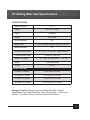
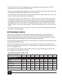
OPERATOR’S MANUAL
10" Sliding
Compound
Miter Saw
Model # 70711
Important
Your new tool has been engineered and manufactured to WEN’s® high standards for
dependability, ease of operation, and operator safety. Properly cared for, it will give you
years of rugged, trouble-free performance.
Pay close attention to the Rules for Safe Operation, Warnings, and Cautions. If you use your
tool properly and only for what it is intended, you will enjoy years of safe, reliable service.
Product questions or need technical support?
Please feel free to contact us!
WenProducts.com
800- 232-1195 M–F 8-5 CST
[email protected]
Table Of Contents
SECTION
PAGE
Specifications . . . . . . . . . . . . . . . . . . . . . . . . . . . . . . . . . . . . . . . . . . . . . . . . . . . . . . . 3
Rules for Safe Operation . . . . . . . . . . . . . . . . . . . . . . . . . . . . . . . . . . . . . . . . . . . 4
General Instructions for All Power Tools . . . . . . . . . . . . . . . . . . . . . . . . . 5
Extension Cords . . . . . . . . . . . . . . . . . . . . . . . . . . . . . . . . . . . . . . . . . . . . . . . . . . . . 8
Grounding Instructions . . . . . . . . . . . . . . . . . . . . . . . . . . . . . . . . . . . . . . . . . . . . 9
Unpacking . . . . . . . . . . . . . . . . . . . . . . . . . . . . . . . . . . . . . . . . . . . . . . . . . . . . . . . . . . . 9
SPECIFIC SAFETY RULES FOR MITER SAW . . . . . . . . . . . . . . . . . . . . . . . . . . . . . . . 10
COMPONENTS OF THE MITER SAW . . . . . . . . . . . . . . . . . . . . . . . . . . . . . . . . . . . . . . 15
ASSEMBLY. . . . . . . . . . . . . . . . . . . . . . . . . . . . . . . . . . . . . . . . . . . . . . . . . . . . . . . . . . . . 15
Attaching the extension supports and miter lock handle . . . . . . . . . . . . . . . . . . . . . 15
Attaching the dust collection bag . . . . . . . . . . . . . . . . . . . . . . . . . . . . . . . . . . . . . . . 15
Mounting the saw . . . . . . . . . . . . . . . . . . . . . . . . . . . . . . . . . . . . . . . . . . . . . . . . . . 16
OPERATION INSTRUCTIONS . . . . . . . . . . . . . . . . . . . . . . . . . . . . . . . . . . . . . . . . . . . . 16
Work piece and work area set up . . . . . . . . . . . . . . . . . . . . . . . . . . . . . . . . . . . . . . 16
General operating instructions . . . . . . . . . . . . . . . . . . . . . . . . . . . . . . . . . . . . . . . . . 16
Using the work piece extension supports . . . . . . . . . . . . . . . . . . . . . . . . . . . . . . . . 17
Adjusting the miter angle . . . . . . . . . . . . . . . . . . . . . . . . . . . . . . . . . . . . . . . . . . . . . 17
Adjusting the bevel angle . . . . . . . . . . . . . . . . . . . . . . . . . . . . . . . . . . . . . . . . . . . . 17
Using the depth stop . . . . . . . . . . . . . . . . . . . . . . . . . . . . . . . . . . . . . . . . . . . . . . . . 18
Making a cut . . . . . . . . . . . . . . . . . . . . . . . . . . . . . . . . . . . . . . . . . . . . . . . . . . . . . . 18
MAINTENANCE AND SERVICING . . . . . . . . . . . . . . . . . . . . . . . . . . . . . . . . . . . . . . . . . 19
Cleaning, maintenance, and lubrication . . . . . . . . . . . . . . . . . . . . . . . . . . . . . . . . . 19
Replacing the blade . . . . . . . . . . . . . . . . . . . . . . . . . . . . . . . . . . . . . . . . . . . . . . . . . 19
Adjusting the fence . . . . . . . . . . . . . . . . . . . . . . . . . . . . . . . . . . . . . . . . . . . . . . . . . 20
Adjusting the miter table indicator . . . . . . . . . . . . . . . . . . . . . . . . . . . . . . . . . . . . . . 21
Adjusting the bevel angle . . . . . . . . . . . . . . . . . . . . . . . . . . . . . . . . . . . . . . . . . . . . 21
Adjusting or replacing the kerf board . . . . . . . . . . . . . . . . . . . . . . . . . . . . . . . . . . . . 21
Cleaning and lubricating the miter saw . . . . . . . . . . . . . . . . . . . . . . . . . . . . . . . . . . 21
TROUBLESHOOTING . . . . . . . . . . . . . . . . . . . . . . . . . . . . . . . . . . . . . . . . . . . . . . . . . . 24
PARTS LIST . . . . . . . . . . . . . . . . . . . . . . . . . . . . . . . . . . . . . . . . . . . . . . . . . . . . . . . . . . 26
ASSEMBLY DIAGRAM . . . . . . . . . . . . . . . . . . . . . . . . . . . . . . . . . . . . . . . . . . . . . . . . . . 27
WARRANTY . . . . . . . . . . . . . . . . . . . . . . . . . . . . . . . . . . . . . . . . . . . . . . . . . . . . . . . . . . 28
2
10" Sliding Miter Saw Specifications
SPECIFICATIONS
Model Number
Rating
Input
Speed
Arbor Diameter
Blade Type
Blade Diameter
70711
120V AC ~ 60Hz
15 Amps
5300 RPM
5/8"
60 Tooth Carbide Tipped General Purpose
10"
Positive Table Stops
0°, 15°, 22.5°, 30° and 45° Right and Left
Positive Bevel Stops
0° and 45° Left only
Blade Tilt Range
0° - 45° Right and Left Miter 0° - 45° left
Scale
1° per scale mark
Weight
36 Lbs
CUTTING CAPACITIES
0º Miter / 0º Bevel
2-3/4 Inch x 12 Inch
45º Miter / 0º Bevel
2-3/4 Inch x 8-1/4 Inch
0º Miter / 45º Bevel
1-9/16 Inch x 12 Inch
45º Miter / 45º Bevel
1-9/16 Inch x 8-1/4 Inch
Package Contents: Sliding Compound Sliding Miter Saw, Carbide
Tipped Blade, 2 pc Table Extensions, Dust Collection Bag, 1–Miter Lock
Handle, 1 Hold Down Clamp, Instruction Manual and Wrench.
3
Rules For Safe Operation
The purpose of safety symbols is to attract your attention to possible dangers. The safety symbols,
and the explanations with them, deserve your careful attention and understanding. The safety
warnings do not by themselves eliminate any danger. The instructions or warnings they give are
not substitutes for proper accident prevention measures.
Symbol Meaning
Safety Alert Symbol:
Indicated danger, warning, or caution, may be used in conjunction with other symbols
or pictographs. Always follow the safety precautions to reduce the risk of fire, electric
shock and personal injury.
NOTE: Advising you of information or instructions is vital to the operation or maintenance of the
equipment
IMPORTANT Servicing requires extreme care and knowledge and should be performed only by a qualified
service technician. For service, we suggest you return the tool to WEN PRODUCTS a division of
Great Lakes Technologies, LLC. for repair. When servicing, use only identical WEN® replacement
parts.
WARNING - Do not attempt to operate this tool until you have read thoroughly
and understand completely all instructions, safety rules, etc…contained in this
manual. Failure to comply can result in accidents involving fire, electric shock,
or serious personal injury. Save this operator’s manual and review frequently for
continuing safe operation and instructing others who may use this tool.
Safe operation of this power tool requires that you read and understand this operator’s manual and
all labels affixed to the tool. Safety is a combination of common sense, staying alert, and knowing
how your tool works.
4
General Instructions for all Power Tools
READ ALL INSTRUCTIONS!!!
• Know your power tool. Read the operator’s manual carefully. Learn the application and limitations as well as specific potential hazards related to this tool.
• Keep guards in place and in working order. Never operate the tool with any guard or cover removed. Make sure all guards are operating properly before each use.
•Remove adjusting keys & wrenches. Form a habit of checking to see keys and adjusting wrenches are removed from tool before turning it on.
• Keep work area clean. Cluttered work areas and work benches invite accidents.
• Do not use in dangerous environments. Do not use power tools near gasoline or other flammable
liquids, in damp or wet locations or expose them to rain. Keep work area well lighted.
• Keep children and visitors away. All visitors should wear ANSI-Z87.1 approved safety glasses and
be kept a safe distance from work area.
• Make workshop childproof with padlocks, master switches, or by removing starter keys.
• Don’t force the tool. It will do the job better and safer at the rate for which it was designed.
• Use the right tool. Do not force the tool or attachment to do a job for which it was not designed.
• Wear proper apparel. Do not wear loose clothing, neckties, or jewelry that can get caught in the
tool’s moving parts and cause personal injury. Non-slip footwear is recommended when working
outdoors. Wear protective hair covering to contain long hair.
• Always wear ANSI-Z87.1 approved safety glasses with side shields. Everyday eyeglasses have
only impact-resistant lenses; they are NOT safety glasses.
• Secure work. Use clamps or a vise to hold work when practical. It’s safer than using your hand
and it frees both hands to operate the tool.
• Do not overreach. Keep proper footing and balance at all times.
• Maintain tools with care. Keep tools sharp and clean for best and safest performance. Follow
instructions for lubricating and changing accessories.
• Disconnect all tools. When not in use, before servicing, or when changing attachments, blades,
bits, cutters, etc…, all tools should be disconnected from power source.
• Reduce the risk of unintentional starting. Be sure switch is off when plugging in.
5
• Use recommended accessories. Consult the operator’s manual for recommended accessories. The use of improper accessories may cause risk of injury.
•Never stand on tool. Serious injury could occur if the tool is tipped or if the blade is unintentionally
contacted.
• Direction of feed. Feed work into a blade or cutter against the direction or rotation of the blade or
cutter only.
• Never leave tool running unattended. Turn power off. Don’t leave tool until it comes to a complete
stop.
• Check damaged parts. Before further use of the tool, a guard or other part that is damaged should
be carefully checked to determine that it will operate properly and perform its intended function. Check for alignment of moving parts, binding or moving parts, breakage of parts, mounting and
any other condition that may affect its operation. A guard or other part that is damaged must be
properly repaired or replaced by an authorized service center to avoid risk of personal injury.
• Protect your hearing. Wear hearing protection during extended periods of operation.
• Keep tools dry, clean, and free from oil and grease. Always use a clean cloth when cleaning. Never use brake fluids, gasoline, petroleum-based products, or any solvents to clean tool.
• PROTECT YOUR LUNGS. Wear a face or dust mask if the operation is dusty.
WARNING - Some dust created by power sanding, sawing, grinding, drilling,
and other construction activities contains chemicals known to cause cancer, birth
defects or other reproductive harm. Some examples of these chemicals are:
•
Lead from lead-based paints
•
Crystalline silica from bricks and cement and other masonry products
•
Arsenic and chromium from chemically treated lumber. Your risk from
these exposures varies, depending on how often you do this type of work. To reduce your exposure to these chemicals, work in a well ventilated area, and work
with approved safety equipment, such as those dust masks that are specially
designed to filter out microscopic particles.
• Guard against electrical shock by preventing body contacting with grounded surfaces. For example: pipes, radiators, ranges, refrigerator enclosures.
• Inspect tool cords and extension cords periodically and, if damaged, have repaired by a qualified service technician. Stay constantly aware of cord location and keep it away from the
rotating wheel.
6
• Never use in an explosive atmosphere. Normal sparking of the motor could ignite fumes.
• Use only outdoor extension cords with approved ground connection that are intended for use outdoors and so marked.
• Avoid awkward operations and hand positions where a sudden slip could cause your hand to
move into the blade. ALWAYS make sure you have good balance.
• Allow the motor to come up to full speed before starting a cut to avoid binding or stalling
• Do not use tool if switch does not turn it on and off. Have defective switches replaced by an authorized service center.
• Replacement parts. All repairs, whether electrical or mechanical, should be made by a qualified
service technician at an authorized service center.
WARNING - when servicing use only identical WEN® replacement parts. Use
of any other part may create a hazard or cause product damage.
• Keep hands away from cutting area. Do not hand hold pieces so small that your fingers go under
the blade guard. Do not reach underneath work or in blade cutting path with your hands and fingers for any reason.
• Before making a cut, be sure all adjustments are secure.
• Always support large work pieces while cutting to minimize risk of blade pinching and kickback. Saw may slip, walk or slide while cutting large or heavy boards.
• Do not remove jammed cutoff pieces until blade has stopped.
• Never start the tool when the blade is in contact with the work piece.
• Never touch blade or other moving parts during use.
• Before changing the setup, removing covers, guards or blades, unplug the saw and remove the
switch key.
• Always turn off saw before disconnecting it to avoid accidental starting when reconnecting to a
power source.
WARNING - DO NOT OPERATE THIS TOOL WHILE UNDER
THE INFLUENCE OF DRUGS, ALCOHOL OR ANY MEDICATION THAT MAY IMPAIR YOUR JUDGMENT OR CONTROL!
7
• Stay alert and exercise control. Watch what you are doing and use common sense. DO NOT operate tool when you are tired. DO NOT RUSH!
• Make sure work area has ample lighting to see the work and that no obstructions will interfere with
safe operation BEFORE performing any work by using your saw.
• Save these instructions. Refer to them frequently and use them to instruct other users. If you loan
someone this tool, loan them these instructions also.
• Use the proper extension cord. Make sure your extension cord is in good condition. When using
an extension cord, be sure to use one heavy enough to carry the current your product will draw. An undersized cord will cause a drop in line voltage resulting in loss of power and overheating. A wire gauge size (A.W.G.) of at least 16 is recommended for an extension cord 25 feet or less in
length. If in doubt, use the next heavier gauge. The smaller the gauge number is, the heavier the
cord is.
• Don’t abuse cord. Never carry tool by the cord or yank it to disconnect from receptacle. Keep cord
from heat, oil, and sharp edges.
EXTENSION CORDS
In the event of a malfunction or breakdown, grounding provides a path or least resistance for electric current and reduces the risk of electrical shock. Tools equipped with an electrical cord
having an equipment-grounding conductor must be plugged into a matching outlet that is properly
installed and grounded in accordance with all local codes and ordinances.
Do not modify the plug provided in any way. If the plug does not fit the outlet, have the proper outlet
installed by a qualified electrician.
The use of any extension cord will cause some loss of power. To keep this to a minimum and to
prevent overheating and motor burned-out; use the table below to determine the minimum wire size
(A.W.G.) of extension cord.
Use only three (3) wire extension cords that have three (3) prong grounding plugs, and three (3)
pole receptacles that accept the tool’s plug.
AMERICAN WIRE GAUGE RATING CHART
EXTENSION CORD
25
50
75
100
125
150
175
200
LENGTH (FEET)
AMPS
AWG
0 to 10.0
18
18
16
16
14
14
12
12
10.1 to 13.0
16
16
14
14
14
12
12
12
13.1 to 15
14
12
12
12
12
12
12
--
15 to 18
14
12
12
12
12
12
--
--
8
GROUNDING INSTRUCTIONS
Tool with three (3) wire grounding plugs (A-in illustration on page 10) is intended for use on a circuit
that has an outlet that looks like the one illustrated in Sketch (B). An adapter (D) may be used to
connect this plug to a two (2) pole outlet (C) if a properly grounded outlet is not available. The
temporary adapter should be used only
until a properly grounded outlet can be
installed by a qualified electrician. The
green colored rigid ear or wire extending
from the adapter must be connected to
a permanent ground such as a properly
grounded outlet box.
UNPACKING
WARNING - to prevent accidental starting that could cause possible serious
personal injury, assemble all parts to your saw before connecting it to power supply. Saw should never be connected to power supply when you are assembling
parts, making adjustments, installing or removing blades, or when not in use.
WARNING - if any parts are missing, do not operate this tool until the missing
parts are replaced. Failure to do so could result in possible serious personal injury.
• Do not discard the packing materials until you have carefully inspected the saw, identified all parts,
and satisfactorily operated your new saw
NOTE: if any parts are damaged or missing, do not attempt to plug in the power cord and turn the
switch on until the damaged or missing parts are obtained and are installed correctly.
9
Specific Safety Instructions for the 10" Miter Saw
WARNING - Do not operate your saw until it is assembled, and you have read
and understand the following instructions and the warning labels on the saw.
Before Operating Your Miter Saw
Check for proper assembly and proper alignment of moving parts.
Understand the function and proper use of:
• Trigger switch/start button
• Lower blade guard
• Miter locks
• Bevel lock knob
• Handle latch
• Arbor lock
Read, understand and follow all operating instructions and safety warnings in this manual.
Read and understand warning labels on the miter saw.
Know the condition of your miter saw. If any part is missing, bent or does not operate properly,
replace the component before you continue to use your saw.
Determine the type of work you are going to be doing before you operate your saw. Properly protect your body including your eyes, hands, face and ears.
Only wear safety goggles that apply with ANSI Z87.1
• When operating power tools, foreign objects can be thrown into your eyes. This could result in permanent eye damage. Glasses or goggles that are not in
compliance with ANSI Z87.1 could break resulting in severe eye injury. Wear a face or dust mask when working in a dusty environment.
• Use ear protection, plugs or muffs, during extended periods of operation.
• Wear a face mask or dust mask when the sawing operation produces dust.
To avoid injury from jams, slips or thrown pieces
• Use the correct 10-inch blade for the material and type of cut. Do not cut materials that may shatter, grab the blade or cause other danger.
• The arrow on the blade must correspond with the cast-in arrow on the upper blade housing. When
you are facing the front of the saw, teeth on the blade should point downward.
• Only use a blade that is sharp and in good condition. Check alignment of the blade after it is installed. Unplug the saw and carefully spin the blade using your hand. The blade should not contact any components of the saw. If so, correct the problem before operating the saw.
• Be sure the blade and blade flanges are clean.
10
• Make sure the blade flanges are properly installed.
• Be sure the arbor bolt and washer are properly installed and tightened.
• Ensure all clamps and locks are tight. Verify there is no excessive play in any parts.
• Allow the blade to reach full speed before cutting.
Do not cut freehand
• The workpiece should be tight against the fence. Verify the workpiece will not rock or twist when
it’s being cut. The area between the workpiece and the saw must be free from debris.
• Make sure there is no gap between the workpiece, fence and base of the saw. A gap could allow
the workpiece to move when it’s being cut.
• Use clamps, fixtures or other devices to hold an unstable workpiece.
Do not cut more than one workpiece at a time
• Allow room so the cut-off workpiece can move after it’s cut. It could create a hazard by becoming
wedged against the blade.
Be very careful when cutting odd shaped, extremely large or very small workpieces
• Plan your work so an odd shaped workpiece cannot slip or pinch the blade. When cutting material
like molding, it must lie flat or be held by a fixture. Do not allow the material to rock, twist or slip.
• Secure sagging workpieces with sawhorses, tables or other additional supports.
• Do not cut small workpieces that you must hold closer than 4 inches (102 mm) from the blade.
• Properly support round material when cutting. Dowel rods and tubing have a tendency to roll while
being cut. This could allow the blade to “bite” into the material causing a hazardous condition. Hold
round material in place using clamps or other fixtures.
• Inspect the workpiece for nails or other foreign objects before it is cut.
• Do not allow anyone to stand behind the saw or close to the workpiece where debris can be
thrown.
• Operate your saw in a clear, safe environment.
To avoid contact with a rotating blade
• Do not wear gloves.
• Do not wear loose clothing or jewelry.
• Tie back long hair.
• Roll long sleeves above the elbow.
To avoid injury from accidental starting of saw
• Unplug the power cord from the electrical outlet.
• Disconnect the lower blade guard.
11
• Install or remove the blade.
• Perform maintenance or make adjustments.
To avoid injury from electrical shock
• Do not touch the metal blades on the power cord plug when removing or installing the plug into an
electrical outlet.
To avoid injury from a fire hazard
• Do not operate the saw near flammable liquids, vapors or gases.
When Operating Your Miter Saw
To avoid injury from unexpected saw movement
• Use the saw on a firm level surface with adequate space for handling and supporting the workpiece.
• Be sure the saw cannot move when operated. Secure the saw to a workbench or table with wood
screws, or bolts, washers and nuts.
Before moving the saw
• Unplug the power cord from the electrical outlet.
• Lock the handle in the down position using the handle latch.
To avoid back injury
• Obtain help when it is necessary to raise the saw more than 10 inches (254 mm).
• Bend your knees when lifting the saw.
• Carry your saw by the carrying handle or base. Do not carry your saw by the power cord or the
trigger handle. Carrying the saw by the power cord could cause damage to the insulation or the
wire connections resulting in electric shock or fire.
Whenever Your Miter Saw is Running
WARNING
• Do not make a careless error. Just because you operate the saw frequently, a neglectful moment
can cause a severe injury.
• Do not lubricate the blade while it is spinning.
Prior to cutting a workpiece
• Test the operation of your saw. If you feel excessive vibration or hear an unusual noise, immediately stop operating the saw. Correct the problem before continued use.
12
Allow movement of the waste portion of the workpiece
• Do not hold it, clamp it, touch it or use a length stop against it. The cut-off waste portion must be
free to move. It could become wedged against the blade causing a hazard.
Avoid awkward hand position
• It is important to position your hand no closer than 4 inches from the blade.
• Do not cross your arms in front of the blade while operating the saw.
Do not force the blade through the workpiece
• Lower the blade through the workpiece fast enough to allow the blade to cut without binding or
bogging down.
Before removing obstructed material
• Release the trigger switch/start button, wait for the blade to stop moving and unplug the power
cord from the electrical outlet.
After completing a cut
• Keep the handle in the down position. Release the trigger switch/start button and wait for the
blade to stop moving.
Motor Safety Protection
Before connecting the power cord to electrical outlet
• Verify the voltage supplied to the saw and the saw’s required voltage is the same. If the supplied
voltage is greater than the required voltage, serious personal injury could result. If the supplied
voltage is lower than required voltage, damage to the motor could result.
• Use proper circuit protection. Connect your saw to a branch circuit that uses a 15-amp time delay
fuse or circuit breaker. Using the wrong size fuse could damage the motor.
• Replace a worn, cut or damaged power cord.
ELECTRICAL REQUIREMENTS
WARNING
• Use only manufacturer’s recommended replacement parts, or equivalent, when servicing this tool.
• Do not touch the metal blades on the power cord plug when removing or installing the plug into an
electrical outlet.
• To avoid electrical hazards, fire hazards, or damage to the tool, use proper circuit protection.
13
Your miter saw is wired at the factory for 120V operation. Connect to a 120V, 15 AMP time delay
fuse or circuit breaker. To avoid shock or fire, replace power cord immediately if it is worn, cut or
damaged in any way.
Use a separate electrical circuit for your tools.
This circuit must not be less than a #12 wire and should be protected with a 15 Amp time delay
fuse. Before connecting the motor to the power line, make sure the switch is in the OFF position
and the electric current is rated the same as the current stamped on the motor nameplate. Running
at a lower voltage will damage the motor.
When operating a power tool outside, use an outdoor extension cord marked "W-A" or "W". These
cords are rated for outdoor use and reduce the risk of electric shock.
This tool is intended for use on a circuit that has a receptacle like the one illustrated: a 3-prong electrical plug (1) and receptacle (2) that has a
grounding conductor. If a properly grounded receptacle is not available, have
a certified electrician check the receptacle.
WARNING - This miter saw is for indoor use only. Do not expose to rain or use
in damp location. This tool must be grounded while in use to protect the operator
from electrical shock.
This tool has an equipped grounding conductor and a grounding plug. The plug
must be used with a matching electrical outlet that is properly installed in accordance with all local codes and ordinances.
Do not modify the power cord plug. If it does not match the electrical outlet, have the proper outlet
installed by a qualified electrician.
Double Insulated
The miter saw is double insulated to provide a double thickness of insulation between you and
the tool’s electrical system. All exposed metal parts are isolated from the internal metal motor components with protecting insulation.
Replacement parts
When servicing use only identical replacement parts.
WARNING - Double insulation does not take the place of normal safety precautions when operating this tool. This tool is intended for indoor use only.
14
Components of a Miter Saw
Handle Latch
Arbor Lock
ASSEMBLY
Attaching the Extension Supports and Miter Lock Handle
1. Insert the ends of the Extension
Supports into the holes in the sides of the Base. Tighten the Wing Screws to hold the Extensions in
place. The upper edge of the Extensions will be level with the surface of the saw. This provides a
wider base for the work material to rest on.
2. Thread the Miter Lock Handle into the opening of the miter handle until securely in place.
Attaching the Dust Collection Bag
3. The Dust Collection Bag slips over the Dust Outlet behind the Blade Housing Assembly. Sawdust
created by cutting is captured in the bag.
MOUNTING THE SAW
The Miter Saw must be mounted on a support before use. This may be a commercially available
support or home made saw table. There are bolt holes provided in each of the four legs of the base. These should be firmly mounted using bolts (not included) to your saw stand or saw table (not
included). This will help prevent tipping or movement of the saw, preventing injury. Also, the use of a
saw table will make it easier to efficiently handle work materials and make more accurate cuts
15
Operating Instructions
WORK PIECE AND WORK AREA SET UP
1. Designate a work area that is clean and well-lit. The work area must not allow access by children
or pets to prevent injury and distraction.
2. Route the power cord along a safe route to reach the work area without creating a tripping hazard
or exposing the power cord to possible damage. The power cord must reach the work area with
enough extra length to allow free movement while working.
3. Use a saw table, saw stand or other means to support the work piece. The Miter Saw must be
mounted in such a way that the surface is level to the ground, and supports used must provide a
surface on the same level as the saw table. If the work surface and any work materials supports
are not level, and on the same level, unwanted bevel angles will appear in the cuts resulting in
poor joinery.
4. Work pieces may be secured to the saw table using the Hold Down Clamp or other clamping
devices (not included). Securing the work piece will provide safety by preventing kick back and by
removing the need to hold work pieces near the blade by hand. Clamping the work piece will also
improve cutting accuracy by preventing the work piece from moving during the cutting operation. 5. When using this saw, work pieces are often quite long. Allow room on both left and right of saw
for extended work pieces.
GENERAL OPERATING INSTRUCTIONS
1. When the Handle is lowered, the Blade Guard raises automatically. When the Handle is raised
the Blade Guard returns to its safety position. Keep hands clear of the Blade when the Handle is
lowered. Never interfere with the proper movement of the Blade Guard.
2. There are locking mechanisms for the miter angle and the Slides. Unlock the Table to set the miter angle, then re-lock it before making the cut. Unlock the Slide using the Slide Lock Wing
Screw before making a cut if the work material is too wide to “chop”. 3. To rotate the Table, press down the Miter Thumb Lever, rotate the Table to the desired angle,
then release the Miter Lock Lever. Notches are machined into the Base of the tool which will lock
the Table into several often used miter angles. These angles are 0º (centered), 15º, 22.5º, 30º
and 45º both left and right cut.
4. On wider pieces, you will have to slide the blade while making the cut. To unlock the Slide, loosen
the Slide Lock Wing Screw at the back of the saw.
5. To make a bevel cut, release the Bevel Lock Lever, rotate the blade assembly to the desired
bevel angle, then lock the blade assembly in place using the Bevel Lock Lever. Making bevel cuts
is discussed in more detail later in this manual.
6. This saw is provided with a Kerf Board. The Kerf Board helps to prevent tear-out on the bottom
side of the work material. The Kerf Board is factory adjusted prior to shipment of this tool so the
16
blade does not contact the Kerf Board during normal operation, including bevel cuts. Adjustment
of the Kerf Board and techniques to prevent tear-out are discussed later in this manual.
7. Before starting work, check the accuracy of the Guide Fence, miter angle and bevel angle. Instructions for checking and adjusting these angles are discussed later in this manual.
8. It is very important that the work material be properly supported before making a cut. The material must be level on the Table. The material must be supported on both ends. Using the
Work Piece Extension Supports is discussed in the next section.
USING THE WORK PIECE EXTENSION SUPPORTS
1. The Work Piece Extension Supports are inserted into each side of the table, and locked in place
using the wing screws. 2. When properly installed, the upper face of the work piece extension supports are level with the
Table, and provide a wider support surface for the work piece. 3. Always support the work piece to be level with the table, and so that after the cut is made the cut off pieces will not fall. You may need to use saw horses or other supports (not included) to
support the work piece.
4. If the work piece is not level, you will make an unintentional bevel cut in the material. If the work
piece is not supported, it will bind the blade and may cause the material to kick back, potentially
causing injury.
ADJUSTING THE MITER ANGLE
1. A miter cut is one that is at an angle across the horizontal surface of the material. You will commonly make 45º miter cuts to join two pieces in a right angle corner. A 30º cut is often used for a scarf joint or to make a chamfered end.
2. To make a miter cut, loosen the Miter Lock Knob by turning it approximately 1/4 turn counterclockwise. Press down the Thumb Lever to unlock the Table. While holding the Thumb Lever
down, move the Table to the desired angle. The Miter Angle Indicator will indicate the selected
angle. The table will lock into place at often used miter angles, including 22.5º, 30º, 45º, and 90º
on both left and right sides.
3. With the Table adjusted to the desired angle, place the work piece flush against the Fence, secure it with the Hold Down Clamp and make the cut.
ADJUSTING THE BEVEL ANGLE
1. A bevel cut is one that is at an angle to the vertical plane of the material. 2. Bevel cuts can be used to miter relatively wide and thin material. Bevel cuts can be used in combination with a miter cut to form a compound angle. Compound angle cuts are often used in
crown moldings, picture frames and similar trim materials.
3. To set the bevel angle, loosen the Bevel Lock Handle at the rear of the saw. To do this, press in
the Lock Button and rotate the Handle 1/2 turn counterclockwise. Move the blade assembly left to
the desired angle. You can read the angle on the Bevel Angle Indicator. Lock the blade assembly
into position by pressing in the Lock Button and rotating the Bevel Lock Handle clockwise. Tighten firmly but not over-tight.
17
4. Make a sample cut in a piece of scrap and check to be sure the bevel angle is correct. If it is not,
correct the angle before cutting your work material.
USING THE DEPTH STOP
1. If you want to make a kerfing or rabbet cut which does not cut through the work piece, you can
use the Depth Stop Screw to control the depth of the cut.
2. To limit blade assembly travel, turn the Depth Stop Screw clockwise. The further you screw down
the Depth Stop Screw, the shallower the cut will be.
3. After the desired cut has been made, return the Depth Stop Screw to its open position by turning
it counterclockwise.
MAKING A CUT
1. Observe all safety and planning items discussed in this manual. Detailed instructions on each of
the following steps are discussed in this manual. Do not make any cuts until you have read this
entire manual and are familiar with the operation of this tool.
2. Release the Locking Pin to allow the blade assembly to come up. Check to be sure the Table is
fixed in place at the desired miter angle. Check to be sure the slide lock is released to allow the
blade assembly to slide freely.
3. Blow any sawdust or debris away from the Fence. Place the work material against the Fence. 4. Make any necessary miter or bevel adjustments.
5. Align the marked location of the cut on the work material with the saw blade. Be aware that the
Saw Blade will remove material from the cut equal to the width of the blade. This is the “kerf”. To
prevent your work piece from being cut too short, align the edge of the blade with your measured
mark, keeping the kerf on the waste side of the cut.
6. Hold the work material in place using the Hold Down Vise. Ensure that the work material is level
and supported securely, using saw horses or supports if necessary.
7. Grip the Saw Handle and squeeze the Trigger to start the Blade turning. 8. Pressing down lightly, move the Blade smoothly across the work material to cut it. With narrow
material, you can press straight down “chopping” the material. With wider material you must
move the Blade across the material to cut it. Do not bear down on the material, use light downward pressure. If the material binds the blade, release the trigger. Keep your hands away from
the Blade.
9. When the cut is completed, raise the blade assembly, wait for the Blade to stop turning, release
the Hold Down Vise and remove the work material from the saw.
18
Maintenance and Servicing
CLEANING, MAINTENANCE, AND LUBRICATION
1 .BEFORE EACH USE,inspectthegeneralconditionofthetool .Checkforloosescrews,misalignmentorbindingofmovingparts,crackedorbrokenparts,damagedelectricalwiring,andany
otherconditionthatmayaffectitssafeoperation .
2 .afterusecleanexternalsurfacesofthetoolwithclean,moistcloth .Topreventaccidents,turn
offthetoolanddisconnectitspowersupplyafteruse .Clean,thenstorethetoolindoorsoutof
children’sreach .
3 .ifthebladehasbecomedirty,useabladecleaner(notincluded)tocleanit .dirtybladeswillbind
moreeasily,andwillmoreoftenoverheatandburnthewoodasitcuts .overheatedbladesdull
moreeasily .
4 .iftheBladehasbecomedull,replaceit .dullbladeswillcauseincreasedtear-outandragged
edgesonthecuts .
5 .occasionallycleantheSlides,rotatingTablecomponentsandothermovingparts .useagood
qualitydrylubricant(notincluded)whichwillnotattractdust .
6 . WARNING!ifthesupplycordofthispowertoolisdamaged,itmustbereplacedonlybyaqualifiedservicetechnician .
LO
REPLACING THE BLADE
1 .unplugthetoolfromitspowersource .
2 .lockthebladeassemblyintheraisedpositionbypushing
inthelockingpin .
3 .usethesuppliedwrenchtoremovetheCenterCover
FixingBoltholdingtheCenterCoverinplacebyturningit
counterclockwise .(SeeFigure2 .)
4 .RemovetheSafetyScrew .(SeeFigure3 .)
O
SE
N
Figure 2
Figure 3
19
Figure 4
LO
O
SE
N
5 .RaisetheBladeGuardandCenterCover .(SeeFigure4 .)
6 .whileholdinginthearborlockButton,usethewrenchto
loosenthearborBoltbyturningitclockwise .(SeeFigure5 .)
note:ThearborBolthasalefthandthread,soitloosensby
turningclockwise .
7 .RemovethearborBolt,outerFlangeandSawBladeby
pullingthemstraightoffthearbor .
8 .ReinstallanewBladeonthearbor .(SeeFigure6 .)Besureto
matchthedirectionmarkedonthenewbladewiththedirection
markedonthesawBladeHousing .
9 .ReplacetheouterFlangeandarborBolt .TightenthearborBolt
securelyusingthewrenchbyturningitcounterclockwise .
10 .RotatetheCenterCoverbackintoplaceandtightenthe
CenterCoverFixingBoltusingthewrenchbyturningit
clockwise .
11 .Releasethelockingpin .
ADJUSTING THE FENCE
1 .TheFenceholdstheworkpieceinafixedpositionwhilethe
Tableandorthebladeassemblyareadjustedinamiteror
bevelangle .
2 .Tomakeaccuratecuts,theFencemustbeperpendicular
(ata90ºangle)totheSawBlade .
3 .Beforebeginningwork,makeatestcutonscrapmaterialwith
theTablesetat90º .
4 .Checkthecutwithanaccuratesquare .Youcanalsoreversethe
twopieces,holdthecutendstogether,andholdagoodstraight
edgealongthesideofthepieces .
Figure 6
5 .ifeithertestrevealsthatthecutisnotatrue90ºangle,youmust
adjusttheFencebefore
beginningwork .
6 .ToadjusttheFence,firstunplugthetool .
7 .lowerthebladeassemblyandlockitinplaceusingthelockingpin .
8 .layareliablecarpenter’ssquareonthetablewithoneedgealongthebladeandtheotheralong
theFence .anyinaccuracyshouldbevisible .noTe:Thesquaremustcontactthesurfaceofthe
blade,nottheteeth,foranaccuratereading .
9 .TheFenceisheldinplacewithboltsateachend .loosentheboltsslightly,andgentlytapthe
Fenceintopositionusingasoftmallet .Retightentheboltsandmakeanothertestcut .Repeatthe
processuntiltheFenceisadjustedaccurately .
10 .oncetheFenceisaccuratelyadjusted,tightentheboltsfirmlyinplace .Recheckonelasttime,
thenproceedtowork .
Figure 5
20
ADJUSTING THE MITER TABLE INDICATOR
1. After you have checked or adjusted the fence to be sure it is at 90º to the Blade, you must check
the accuracy of the Miter Table Angle Indicator.
2. Loosen the screw holding the Angle Indicator in place. Rotate it until the pointer is exactly on 90º. Retighten the screw.
ADJUSTING THE BEVEL ANGLE
1. For making accurate cuts, the Saw Blade must be adjusted to be exactly vertical to the Table.
2. To check the angle, have the blade assembly in its normal upright position. Make a cut on a piece
of flat sided, fairly thick scrap material.
3. Check the cut with an accurate square. The cut should be at exactly 90º. You can also check by
rotating one cut-off piece 180º and hold the cut ends together. If the cut is not exactly vertical, the
two pieces will form a slight angle.
4. If necessary, the bevel angle can be corrected by adjusting the Bevel Adjustment Screw on the
right side under the Bevel Locking Lever. 5. Once the bevel angle is adjusted, adjust the Bevel Angle Indicator to read 0º when the Saw Blade
is in the vertical position. Loosen the screw holding the Indicator in place, adjust it to be exactly
over the 0º mark, then retighten the screw.
ADJUSTING OR REPLACING THE KERF BOARD
1. If the Kerf Board becomes damaged it must be replaced. 2. Remove the four screws holding the Kerf Board in place. 3. Install a new Kerf Board. Replace the four screws and tighten them slightly.
4. To adjust the Kerf Board, lower the Saw Blade and lock it down with the Locking Pin. Adjust the
Kerf Board so the right side of the Blade slightly clears the edge of the Kerf Board. Loosen the
Bevel Lock and set the Bevel Angle at 45º left. Ensure that the left side of the Blade clears the
Kerf Board. Tighten the four screws holding the Kerf Board in place.
CLEANING AND LUBRICATING THE MITER SAW
1. Observe the Dust Bag while using the saw. Empty the sawdust into an appropriate container
when the bag is full.
2. Occasionally wipe or blow off sawdust that accumulates on the saw. Saw dust on the Fence can
cause you to make inaccurate cuts.
3. Keep the Slides free of sawdust. Wipe or blow them off as required. Use a dry lubricant or wax on the slides. Do not use an oil or grease lubricant, as this will attract dust.
4. Occasionally lubricate the pivot point of the Table as well as other moving parts with a dry lubricant.
21
Troubleshooting
Problem
Possible Causes
Likely Solutions
Tool will not start
1. No power at outlet.
1. Check power at outlet.
2. Cord not connected.
2. Check that cord is plugged in.
1. Low power supply or
improper
1. Check power supply and power cords.
2. Extension cords.
2. Check Carbon Brushes. Replace if damaged or worn.
Tool operates sporadically or at low
power
Wood burns at ends
when cut
3. Worn or cracked carbon brushes.
1. Dirty blade.
2. Material is binding. 1. Clean Blade using blade cleaner or mineral spirits. 2. Check position of work material on Table. 3. Material must be flat, flush against Fence
and supported on ends.
Material frays or
chips out.
1. Finished side is down
2. Blade is chipped or dull.
3. Blade is inappropriate
for material. 4. Material is unsupported.
1. Always have finished side of material up or
facing you. 2. Bottom and back side are prone to chip out
3. Check for damaged teeth. Sharpen or replace blade.
4. Check blade manufacturer’s recommendations for material being cut. For cross cutting hard wood and for precision cuts use a
thin kerf blade with 60 or more teeth.
5. Use a thin piece of scrap material, such
as 1/4” plywood, underneath or behind the
material to support the edges of the material as it is being cut.
Follow all safety precautions whenever diagnosing or servicing the tool.
Disconnect power supply before service.
22
Troubleshooting
Problem
Possible Causes
Blade binds, slowing 1. Material is misaligned
or stopping saw.
on the saw or ends
are not supported.
Likely Solutions
1. Material must be flat on table, flush against
the fence and supported on both ends.
2. Check condition of material and check com2. Material is wet, conpatibility of blade to material.
taminated or inappropriate blade is being
used.
Follow all safety precautions whenever diagnosing or servicing the tool.
Disconnect power supply before service.
23
Parts List
Part No.
Stock No.
Description
Qty
Part No.
Stock No.
Description
Qty
1
70711-001
Bolt M6X25
2
38
70711-038
Spring
1
2
70711-002
Base
1
39
70711-039
Bend Arm
1
3
70711-003
Extension Support
2
40
70711-040
Flat Washer
2
4
70711-004
Wing Screw
2
41
70711-041
Lock Nut
1
5
70711-005
Rubber Feet
4
42
70711-042
Washer
2
6
70711-006
Bolt M8X50
1
43
70711-043
Bolt
1
7
70711-007
Bolt M5X10
4
44
70711-044
Bevel Lock Lever
1
8
70711-008
Spring Washer
8
45
70711-045
Lock Pin Spring
1
9
70711-009
Flat Washer
4
46
70711-046
Bolt
1
10
70711-010
Plate
1
47
70711-047
Bolt M5X14
2
11
70711-011
Rub Slice
1
48
70711-048
Spacer
4
12
70711-012
Pin
1
49
70711-049
Oil Cover
2
13
70711-013
Spring
1
50
70711-050
Bearing
2
14
70711-014
Pin 3X20
1
51
70711-051
Rod
2
15
70711-015
Miter Lock Handle
1
52
70711-052
Mount
1
16
70711-016
Plate
1
53
70711-053
Line Button
2
17
70711-017
Pin
1
54
70711-054
Washer
2
18
70711-018
Pointer
1
55
70711-055
Bolt M6X10
4
19
70711-019
Bolt M4X12
2
56
70711-056
Limit Plate
1
20
70711-020
Bolt M4X8
9
57
70711-057
Slide Lock Screw
1
21
70711-021
Kerf Board
1
58
70711-058
Handle Ball
1
22
70711-022
Plate
1
59
70711-059
Lock Spring
1
23
70711-023
Plate
1
60
70711-060
Lock Pin
1
24
70711-024
Bolt M8X30
1
61
70711-061
Spring Pin
1
25
70711-025
Table
1
62
70711-062
Cover Stand
1
26
70711-026
Flat Washer
1
63
70711-063
Screw
1
27
70711-027
Lock Nut
1
64
70711-064
Bolt
1
28
70711-028
Rail Fence
1
65
70711-065
Washer
2
29
70711-029
Flat Washer
8
66
70711-066
Lock Button
1
30
70711-030
Spring Washer
8
67
70711-067
Link Pole Bolt
2
31
70711-031
Bolt M6X30
4
68
70711-068
Link Pole
1
32
70711-032
Wing Screw
1
69
70711-069
Brush Cover
2
33
70711-033
Hold Down Clamp
1
70
70711-070
Carbon Brush
4
34
70711-034
Bolt
1
71
70711-071
Brush House
2
35
70711-035
Flat Washer
1
72
70711-072
Motor House
1
36
70711-036
Pointer
1
73
70711-073
Bolt
4
37
70711-037
Nut
2
74
70711-074
Brush House Spring
2
75
70711-075
Stator
1
24
Parts List
Part No.
Stock No.
Description
Qty
Part No.
Stock No.
Description
Qty
76
70711-076
Screw
2
103
70711-103
Inner Flange
1
77
70711-077
Block Circle
1
104
70711-104
Blade
1
78
70711-078
Bearing
1
105
70711-105
Outer Flange
1
79
70711-079
Rotor
1
106
70711-106
Arbor Bolt (LEFT)
1
80
70711-080
Bearing
1
107
70711-107
Lock Nut
1
81
70711-081
Arbor Lock
1
108
70711-108
Small Cover
1
82
70711-082
Lock Button Spring
1
109
70711-109
Large Cover
1
83
70711-083
Spring Washer
2
110
70711-110
Washer
1
84
70711-084
Block Plate
1
111
70711-111
Bolt
1
85
70711-085
Spring
1
112
70711-112
Bolt M8X12
1
86
70711-086
Pin
1
113
70711-113
Spring
1
87
70711-087
Blade Housing
1
114
70711-114
Blade Guard
1
88
70711-088
Bolt M6X10
1
115
70711-115
Center Cover
1
89
70711-089
Bolt M6X20
2
116
70711-116
Switch
1
90
70711-090
Dust Pipe
1
117
70711-117
Bolt
2
91
70711-091
Dust Collection Bag
1
118
70711-118
Handle
1
92
70711-092
Screw
1
119
70711-119
Bolt
2
93
70711-093
Lock Washer
2
120
70711-120
Bolt
2
94
70711-094
Bearing
1
121
70711-121
Up Handle
1
95
70711-095
Spring Washer
1
122
70711-122
Bolt
2
96
70711-096
Gear
1
123
70711-123
Press Plank
1
97
70711-097
Front Cover
1
124
70711-124
Power Cord
1
98
70711-098
Bearing
1
125
70711-125
Cord Sleeve
1
99
70711-099
Arbor
1
126
70711-126
Down Handle
1
100
70711-100
Key 4X13
1
127
70711-127
Spanner
1
101
70711-101
Bearing Cover
1
128
70711-128
Bearing
1
102
70711-102
Bolt
3
25
Assembly Diagram
26
Assembly Diagram
27
WARRANTY
Warranty
WEN Products is committed to build tools that are dependable for years. Our warranties are consistent with this commitment and our dedication to quality
LIMITED WARRANTY OF WEN CONSUMER POWER TOOLS PRODUCTS FOR HOME USE GREAT LAKES TECHNOLOGIES, LLC ("Seller") warrants to the original purchaser only, that all WEN consumer power tools will be free from defects in material or workmanship for a period of one year from date of purchase. Ninety days for all WEN products, if the tool is used for professional use.
SELLER'S SOLE OBLIGATION AND YOUR EXCLUSIVE REMEDY under this Limited Warranty and, to the
extent permitted by law, any warranty or condition implied by law, shall be the repair or replacement of parts,
without charge, which are defective in material or workmanship and which have not been misused, carelessly
handled, or misrepaired by persons other than Seller or Authorized Service Center. To make a claim under
this Limited Warranty, you must return the complete power tool product; transportation prepaid, to Great
Lakes Technologies, LLC – 501 Davis Road – Elgin, IL. 60123 with a copy of the original receipt which is legible and clearly defines Date of Purchase including month and year and Place of Purchase.
THIS LIMITED WARRANTY DOES NOT APPLY TO ACCESSORY ITEMS SUCH AS CIRCULAR SAW BLADES, DRILL BITS, ROUTER BITS, JIGSAW BLADES, SANDING BELTS, GRINDING WHEELS AND OTHER RELATED ITEMS.
ANY IMPLIED WARRANTIES SHALL BE LIMITED IN DURATION TO ONE YEAR FROM DATE OF PURCHASE. SOME STATES IN THE U.S., SOME CANADIAN PROVINCES DO NOT ALLOW LIMITATIONS ON HOW LONG AN IMPLIED WARRANTY LASTS, SO THE ABOVE LIMITATION MAY NOT APPLY TO YOU.
IN NO EVENT SHALL SELLER BE LIABLE FOR ANY INCIDENTAL OR CONSEQUENTIAL DAMAGES (INCLUDING BUT NOT LIMITED TO LIABILITY FOR LOSS OF PROFITS) ARISING FROM THE SALE OR
USE OF THIS PRODUCT. SOME STATES IN THE U.S. AND SOME CANADIAN PROVINCES DO NOT
ALLOW THE EXCLUSION OR LIMITATION OF INCIDENTAL OR CONSEQUENTIAL DAMAGES, SO THE ABOVE LIMITATION OR EXCLUSION MAY NOT APPLY TO YOU.
THIS LIMITED WARRANTY GIVES YOU SPECIFIC LEGAL RIGHTS, AND YOU MAY ALSO HAVE OTHER
RIGHTS WHICH VARY FROM STATE TO STATE IN THE U.S., PROVINCE TO PROVINCE IN CANADA AND FROM COUNTRY TO COUNTRY.
THIS LIMITED WARRANTY APPLIES ONLY TO PORTABLE ELECTRIC TOOLS, BENCH POWER TOOLS,
OUTDOOR POWER EQUIPMENT AND PNUMATIC TOOLS SOLD WITHIN THE UNITED STATES OF
AMERICA, CANADA AND THE COMMONWEALTH OF PUERTO RICO. FOR WARRANTY COVERAGE WITHIN OTHER COUNTRIES, CONTACT THE WEN CUSTOMER SUPPORT. 28